1
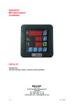
MIKSTER MCC 2100 Microprocessor Controller - User’s Manual
Sp. z o.o. (Ltd.)
41-250 Czeladź ul. Wojkowicka 21, POLAND
Tel. +48 (0-32) 265 70 97, 265 76 41, 763-77-77
Fax: 763–75-94
www.mikster.com
[email protected]
MIKSTER MCC 2100 Microprocessor Controller – User’s Manual
CONTENTS
page
1. TECHNICAL DATA ........................................................................................................................................... 3
2. “MIKSTER MCC 2100” CONTROL DESK .........................................................................................................4
3. “MIKSTER MCC 2100” - STARTING WORK ......................................................................................................4
3.1. Real time clock setting ...............................................................................................................................5
4. PROGRAMMING OF TECHNOLOGICAL PROCESSES ...................................................................................6
4.1. Execution of a program stored in memory .................................................................................................7
4.2. Stopping of execution of a currently executed program .............................................................................8
4.3. Automatic start of the process .....................................................................................................................8
4.4. Editing of preset parameters during operation of the controller ..................................................................9
5. SERVICE FUNCTIONS OF THE CONTROLLER ..............................................................................................9
5.1. Controller configuring .................................................................................................................................10
5.2. Zero correction for measurement channels ..............................................................................................13
5.3. Test of correct work of keys and relays ....................................................................................................14
5.4. Defining of state of relays and conditions of cycle closing for particular cycles .......................................15
5.5. Defining of working conditions for relays ..................................................................................................16
5.6. Defining of alarms .....................................................................................................................................24
5.7. Deleting all controller settings ...................................................................................................................26
5.8. Definition of relays modes for “PAUSE” ....................................................................................................26
5.9. Definition of relays modes for “STOP” ......................................................................................................27
5.10. Settings and method of activating the "WASHING" process .............................................................28
5.11. Defining relays for the "WASHING" process ....................................................................................29
5.12. Defining relays for the "automatic ventilation" mode .........................................................................30
5.13. Checking of the smoking chamber operation time ............................................................................30
6. Directions for connecting the controller to personal computer ...............................................................31
7. Procedure for connecting a printer to the controller ...............................................................................32
8.MCC-2100 controller errors table………………………………………………………………………………..32
-2-
17.06.2004
MIKSTER MCC 2100 Microprocessor Controller – User’s Manual
1. TECHNICAL DATA
OVERALL DIMENSIONS:
POWER SUPPLY:
CASING:
PROTECTION DEGREE:
HUMIDITY:
TEMPERATURE:
DISPLAY UNIT:
Width
190 mm
Height
290 mm
Depth
50 mm
24 V AC (transformer in the set)
“FRONT PANEL” type, single
element
from front
IP 65
0.75 % (relative humidity)
ambient -20..+70 °C
working
0..+60 °C
seven-segment LED displays
foil, 50 keys
KEYBOARD:
SIGNALLING OF STATES: 18 LED diodes
TRANSMITTER OUTPUTS: 24 x short-circuiting switch
(220V,2A)
Optional
ANALOG OUTPUTS:
8 x (PT-100 or 0..20 mA or
ANALOG INPUTS:
4..20mA)
8 x separated input Umax=220V
DIGITAL INPUTS:
1 x RS-232 (Printer)
SERIAL
1 x RS-485 (PC)
COMMUNICATION:
-3-
17.06.2004
MIKSTER MCC 2100 Microprocessor Controller – User’s Manual
2. CONTROL DESK “MIKSTER MCC 2100”
All operations connected with programmer start-up, programming, manual alterations etc. are carried
out through control desk.
Keys on the desk are arranged into the following function keypads:
• numeric display keypad 1
• NUMERIC keys along with FUNCTION keys 2
• OUTPUT DEVICES MODE signaling keys and diodes 3
• keys and diodes for TECHNOLOGICAL PROCESS SIGNALING 4
Whole information concerning the state of working programmer (operation mode, values of set
and read parameters etc.) are displayed on alphanumeric display units and signaled by LED diodes.
-4-
17.06.2004
MIKSTER MCC 2100 Microprocessor Controller – User’s Manual
3. “MIKSTER MCC 2100” – STARTING WORK
After switching on power all displays and diodes light, after 5 seconds they should fade, that confirms
correct work of the system; the controller turns to ‘ready to work’ mode.
3.1. Real time clock setting
In order to set correct time we should:
• press and hold for a moment the
button, word “CODE” will be displayed and green digits
“000” will blink,
• using numeric keys enter first part of the code: (as a standard – “888”), and
press the
button, red digits “000” will blink,
• using numeric keys enter second part of the code: (as a standard – “888”), and press
the
button, two red digits showing hour will blink,
• using numeric keys enter current hour and press the
will blink,
button, two red digits showing minutes
• using numeric keys enter current minutes and press the
button
(in the field “WILGOTNOSC ZADANA” (“PRESET HUMIDITY”) two digits showing year will
blink),
• using numeric keys enter current year (last two digits only) and press
button (in the field “CZAS CYKLU - godziny” (“CYCLE TIME – hours”) two digits
the
showing month will blink),
• using numeric keys enter current month and press the
button (in the field “CZAS CYKLU minutes” (“CYCLE TIME – minutes”) two digits showing day will blink),
• using numeric keys enter current day and press the
button.
After having finished the above steps, the controller stores newly entered time in memory and turns to
‘ready to work’ mode.
-5-
17.06.2004
MIKSTER MCC 2100 Microprocessor Controller – User’s Manual
4. PROGRAMMING OF TECHNOLOGICAL PROCESSES
In order to create a new program or edit an existing one, we should:
• press the
blink,
button, word “CODE” will be displayed and green (or yellow) digits “000” will
• using numeric keys enter first part of the code: “222” and
press the
button, red digits “000” will blink,
• using numeric keys enter second part of the code: “222”
and press the
button, green digit showing program number will blink,
• using numeric keys enter program number (1-50), which we wish to create, or else correct it in case
when program with such number already exists, and press the
button,
Now we may begin editing of the program, consisting of maximum 20 cycles. Number of currently
edited cycle is displayed in the
(1-20) by pressing the
(“STEP”) field. We shift from cycle to cycle
button.
In each cycle we may preset the following parameters:
•
•
•
•
•
temperature in the chamber,
temperature of the bar (baton in Polish - translator’s note),
humidity,
cycle duration,
cycle name,
After having set the controller in programming mode, green (yellow) digits will blink in the field
“TEMPERATURA KOMORY” (“CHAMBER TEMPERATURE”). In order to preset the required
parameters we should:
• select name responding to particular cycle using keypad (keys showing names of cycles (-4-)), by
pressing on appropriate name; selection will be confirmed by control diode indication at the
selected name,
• using numeric keys set the required chamber temperature value and press the
-6-
17.06.2004
MIKSTER MCC 2100 Microprocessor Controller – User’s Manual
button, green (yellow) digits showing bar temperature will blink,
•
using numeric keys set the required bar temperature value and press the
button, green (yellow) digits showing humidity will blink,
•
using numeric keys set the required humidity value and press the
button, green (yellow) digit (or digits) showing cycle duration in hours will blink,
•
using numeric keys set the number of hours of cycle duration, and press the
button, green (yellow) digits showing cycle duration in minutes will blink,
•
using numeric keys set the cycle duration in minutes,
•
press the
•
we repeat all steps performed during editing of the first cycle, and so on.
•
after having set appropriate values for all required cycles (maximum 20), we press the
button, therefore shifting to editing of next cycle,
button in order to close the programming process, or the
(“PROG. / CORRECT”) button
in order to edit next program. We proceed with selection of program number and the programming
process in the same manner as described at the beginning of this chapter.
4.1. Execution of a program stored in memory
In order to execute program, which has been previously stored in memory of the controller, we should:
• press the
button, green (yellow) digit showing program number will blink,
• using numeric keyboard we set program number, which we wish to execute and we press the
button,
• using the
• by pressing the
button, we select the step number, from which program is to be executed,
button, we start the program.
Step, which time of execution has been set at 00:00 will not be executed.
-7-
17.06.2004
MIKSTER MCC 2100 Microprocessor Controller – User’s Manual
4.2. Stopping of execution of a currently executed program
At any time we are able to abort program execution without possibility to restart it, in order to do
that we should:
• press the
button two times; the controller turns to ‘ready to work’ mode.
It is also possible to abort the executed program, and then return to its execution, in order to do that we
should:
(“PAUSE / CONTINUE”) button; the word “PAUSE” will be displayed and the
• press the
controller will abort program execution,
• in order to restart program execution we should press the
button again.
4.3. Automatic start of the process
The MIKSTER MCC 2100 controller allows starting program at any previously set hour. In
order to allow for auto-start of the controller we should:
• press the
button; green (yellow) digit (digits) showing program number will blink,
• using numeric keyboard we set program number, which we wish to start automatically,
• press the
button; all previously set program parameters will be displayed (by pressing the
button we may preview parameters of the following steps),
• press the
button; green (yellow) digits showing the hour of automatic start of technological
program will blink; current time will be displayed in red,
• using numeric keyboard we set the hour of automatic start of the process,
button; green (yellow) digits showing the minutes of automatic start of
• press the
technological program will blink,
• using numeric keyboard we set the minutes of automatic start of the process,
• press the
button and the controller turns to ‘waiting for automatic program start’ mode; the
word “AUTO” and diodes on the
and
-8-
buttons will blink.
17.06.2004
MIKSTER MCC 2100 Microprocessor Controller – User’s Manual
At the hour preset by us the controller will automatically start execution of appropriate program from
the first step. Aborting of the process has been described in point 4.2.
4.4. Editing of preset parameters during operation of the controller
There is an option of correcting previously set parameters while the controller executes the program.
In order to do that we should (during execution of a program):
• press the
button,
• using numeric keys set the required chamber temperature and press the
showing bar temperature will blink,
• using numeric keys set the required bar temperature value and press the
(yellow) digits showing humidity will blink,
button; green digits
button; green
• using numeric keys set the required humidity value and press the
digit (or digits) showing cycle duration in hours will blink,
button; green (yellow)
• using numeric keys set the cycle duration in hours, and press the
digits showing cycle duration in minutes will blink,
button; green (yellow)
• using numeric keys set the cycle duration in minutes,
• press the
parameters.
button, the controller will continue program execution with new working
NOTE !!!
Alterations made during operation of the controller will be valid only until closing of the
technological process. After program closing the controller “remembers” program with data set
during the programming process.
5. SERVICE FUNCTIONS OF THE CONTROLLER
The controller has at its disposal highly extended service functions allowing for adjusting its
parameters and manner of work to individual needs of its user. Suitable settings performed by service
functions are stored in the controller memory, and used during execution of a selected program.
-9-
17.06.2004
MIKSTER MCC 2100 Microprocessor Controller – User’s Manual
NOTE !!!
These service functions may be used only by an authorized service person or a trained person !!!
These functions should not be used unless it is absolutely necessary !!!
In order to launch service functions we should:
• press and hold for a moment the
green digits “000” will blink,
and
buttons; word “CODE” will be displayed and
• using numeric keys enter first part of the code: “111”, and press the
will blink,
• using numeric keys enter second part of the code: “111”, and press the
word “SERVICE” will appear,
button; red digits “000”
button; blinking
Now it is possible to select appropriate service function number. Particular numbers mean:
0.
1.
2.
3.
4.
5.
6.
7.
8.
9.
Program version
Setup
AC converter
Tests
Definition of cycle relays
Relay type
Alarms
Initializations
Relays condition for “PAUSE”
Relays definition “STOP”
5.1. Controller configuring
In order to carry out basic configuration of the controller we should:
• press and hold for a moment the
digits “000” will blink,
and
buttons; word “CODE” will appear and green
• using numeric keys enter first part of the code: “111”, and press the
will blink,
• using numeric keys enter second part of the code: “111”, and press the
word “SERVICE” will appear,
- 10 -
button; red digits “000”
button; blinking
17.06.2004
MIKSTER MCC 2100 Microprocessor Controller – User’s Manual
• press the
button; number of the SETUP “F00” cell will be displayed in green (yellow),
value attributed to particular parameter will be displayed in red.
• using numeric keys enter the value in a particular cell;
• press the
button; therefore moving to the next SETUP cell;
• using numeric keys enter the value in a particular cell;
We repeat the above steps until required values are set in each SETUP cell. Meaning of particular
cells is shown in the table below:
FUNCTION
NO.
VALUE SET
BY FACTORY
RANGE
F 00
0
0..31
F 01
F 02
F 03
F 04
F 05
F 06
F 07
F 08
F 09
F 10
F 11
F 12
F 13
F 14
0
0
380
220
0
1
111
111
222
222
888
888
150
150
0..450
0..255
0..2
0..255
0..999
0..999
0..999
0..999
0..999
0..999
0..255
0..255
F 15
F 16
F 17
F 18
60
12.0
1
0
0..512
0..25.5
0..254
0..1
F 19
0
0..24
- 11 -
CHARACTERISTICS
Number in the network: RS - 485 if we have at our disposal only one
controller, then we leave the preset
value as a default value, that is “0”,
when we have two or more
controllers connected in the
network, we attribute to them
successive numbers.
Free
Free
Smoke generator board temperature
Smoke temperature
Delta status
Registration recording frequency
Code for SET-UP (3 digits)
Code for SET-UP (3 digits)
Code for programming (3 digits)
Code for programming (3 digits)
Code for clock (3 digits)
Code for clock (3 digits)
Maximum preset temperature
Maximum preset temperature of the
bar
Time after turning off power
Preset Tk value (Tk zad) exceeded
Frequency of printing on printer
Speed of transmission 0 – 9600,
1 – 19200
Number of relay, in relation to
which ventilation process is turned
on
17.06.2004
MIKSTER MCC 2100 Microprocessor Controller – User’s Manual
F 20
F 21
0
0
0..20
0..24
F 22
0
0..200
F 23
0
0..24
F 24
F 25
0
95
0..255
F 26
2
F 27
2
F 28
5
F 29
15
F 30
150
F 31
20
F 32
20
F 33
F 34
Ventilation time
Number of the relay, in relation to
which time allowed between
washing process is being calculated
Allowed number of hours between
washing processes
Number of signaling relay. End of
process
Operation time the process end relay
Not used
Not used
Not used
Not used
Not used
Not used
Not used
0
0..1
0
0..1
F 35 – F 47
F 48
0
0..1
F 49
0
0..1
F 50
0
0..1
- 12 -
Not used
Process activation using computer
0 – off
1 – on
(in case if value “1” is set, it is
impossible to activate the process
using the controller keyboard)
Process ID
0 – off
1 – on
Not used
Temperature measurement unit
0 – 0C
1 – 0F
Accuracy of displayed temperature
value
0 – 1 0C
1 – 0.1 0C
Recording accuracy
0 – 1 0C
1 – 0.2 0C
17.06.2004
MIKSTER MCC 2100 Microprocessor Controller – User’s Manual
F 51
0
0
Chamber temperature measurement
0 - channel 1
1 - channel 6
F 52
F 53
0
0
0..1
0..1
F 54
0
0..1
Free
Transmission protocol
0 - Mikster-bus
1 - MODBUS-RTU
Power output ON / OFF for the PID
controller
0 – OFF
1 – ON
F 55
0
0..1
After having set particular parameters we press the
stored in memory.
Loop on / off
Controller work looping
0 – off
1 – on
button and all settings in SETUP will be
5.2. Zero correction for measurement channels
In order to make a correction we should:
•
press and hold for a moment the
(yellow) digits “000” will blink,
and
buttons; word “CODE” will appear and green
• using numeric keys enter first part of the code: “111”, and press the
will blink,
• using numeric keys enter second part of the code: “111”, and press the
word “SERVICE” will appear,
• press the
button; red digits “000”
button; blinking
button;
• using keys
or
select number of channel for correction; channel number will be
displayed in green (yellow) in the KROK (“STEP”) field;
• connect model resistor of R = 100 Ω resistance to a selected channel;
- 13 -
17.06.2004
MIKSTER MCC 2100 Microprocessor Controller – User’s Manual
• press the
button,
• connect model resistor on sensor characteristic (e.g. 138.5Ω for 100°C ) .
• Make the temperature readout on selected channel correct by turning potentiometers on backboard
of the controller. Temperature will be displayed in the “ZEGAR” (“CLOCK”) field.
Similarly to the above operations we should carry out correction on all active measurement
channels !
In order to leave the option of measurement channels correction press the
button.
5.3. Test of correct work of keys and relays
In order to perform keyboard and displays test we should:
•
press and hold for a moment the
digits “000” will blink,
and
buttons; word “CODE” will appear and green
• using numeric keys enter first part of the code: “111”, and press the
will blink,
• using numeric keys enter second part of the code: “111”, and press the
word “SERVICE” will appear,
•
press the
•
using numeric keys enter number of test to be performed.
button; red digits “000”
button; blinking
button; all displays and signaling diodes will fade;
Results of particular tests are shown in the table below:
Test number
0
1
2
3
4
5
6
7
8
9
Test result
Switches off all lights and displays
Switches on all lights and displays
Displays successive digits on numeric display
Tests all signaling diodes one by one
Tests all relays one by one
Tests relays by pressing buttons
Two-mode input state
Free
Free
Free
In order to select another test we should press attributed to it number on numeric keyboard.
- 14 -
17.06.2004
MIKSTER MCC 2100 Microprocessor Controller – User’s Manual
Press the
button to leave “TEST” mode.
5.4. Defining of state of relays and conditions of cycle closing for particular cycles
The MCC 2100 controller allows for free configuring and defining of relays for each of cycles. In
order to do that we should:
•
and
press and hold for a moment the
green digits “000” will blink,
buttons; the word “CODE” will appear and
• using numeric keys enter first part of the code: “111”, and press the
will blink,
button; red digits “000”
• using numeric keys enter second part of the code: “111”, and press the
word “SERVICE” will appear,
•
press the
•
select name of cycle, for which we wish to define relays modes;
•
by pressing the
or
/ off in particular cycle;
•
using the
button; red fields by the cycles names will blink;
button, select number of a relay (1-24), which we wish to turn on
key, set whether selected relay is to be switched on (ON), or off (OFF) in
particular cycle; relay mode may also be changed with the keys:
•
pressing the
or off;
button; blinking
or
- off, and
- on;
button, select next number of relay and define whether it is to be on
Relay number will be displayed in the “program” field, and its preset state is signaled by lighting of
proper diode on buttons and displayed words “On” or “Off” in the ”chamber temperature” field.
Having preset all relays modes for particular cycle we must:
• using the
table below:
Number
key, set manner of cycle closing; conditions of closing cycle are shown in the
Condition of closing cycle
- 15 -
17.06.2004
MIKSTER MCC 2100 Microprocessor Controller – User’s Manual
0
1
2
3
4
5
6
7
8
9
10
11
12
13
14
15
16
17
18
End of cycle after reaching preset time
End of cycle after exceeding preset value of
temperature in the chamber
End of cycle after exceeding preset value of bar
temperature
End of cycle after exceeding preset value of
humidity
End of cycle after reaching preset time or after
exceeding preset value of temperature in the
chamber
End of cycle after reaching preset time or after
exceeding preset value of bar temperature
End of cycle after reaching preset time or after
exceeding preset value of humidity
End of cycle after reaching preset time and after
exceeding preset value of temperature in the
chamber
End of cycle after reaching preset time and after
exceeding preset value of bar temperature
End of cycle after reaching preset time and after
exceeding preset value of humidity
End of cycle after temperature drop in the chamber
below preset value
End of cycle after temperature drop in bar below
preset value
End of cycle after humidity drop below preset
value
End of cycle after reaching preset time or after
temperature drop in the chamber below preset value
End of cycle after reaching preset time or after
temperature drop in bar below preset value
End of cycle after reaching preset time or after
humidity drop below preset value
End of cycle after reaching preset time and after
temperature drop in the chamber below preset value
End of cycle after reaching preset time and after
temperature drop in bar below preset value
End of cycle after reaching preset time and after
humidity drop below preset value
In order to configure next cycle we should:
●
press name of appropriate cycle and further proceed exactly as in the case of defining previous
cycle.
Configuring will be ended after pressing the
key.
- 16 -
17.06.2004
MIKSTER MCC 2100 Microprocessor Controller – User’s Manual
5.5. Defining of working conditions for relays
The MIKSTER MCC 2100 controller allows for defining of working conditions for each of the 24
relays separately.
Meaning of relays working parameters:
P0 – Time type
0 – Relay off
1 – Relay on / off in accordance with program
2 – turning on with time lag
3 – turning off with time lag
4 – pulse generator
P1 – time Ta
P2 – time Tb
P3 – type of regulator
0 – regulator on
1 – regulator “warming”
2 – regulator “cooling”
3 – “ warming” straight hysteresis
4 – “ cooling” straight hysteresis
P4 - number of measurement channel
0 – chamber temperature
1 – free
2 – bar temperature
3 – board temperature
4 – humidity
5 – smoke temperature
P5 – shift of preset value of the regulator in relation to preset value in program
P6 – shift of algorithm level of work with dynamic preset value
P7 – “lower” hysteresis
P8 – “upper” hysteresis
In order to perform operation of defining parameters for particular relays we should:
•
press and hold for a moment the
digits “000” will blink,
and
buttons; word “CODE” will appear and green
• using numeric keys enter first part of the code: “111”, and press the
will blink,
• using numeric keys enter second part of the code: “111”, and press the
word “SERVICE” will appear,
• press the
button; red digits “000”
button; blinking
button;
- 17 -
17.06.2004
MIKSTER MCC 2100 Microprocessor Controller – User’s Manual
•
using the
button select number of a relay, parameters of which we wish to set; number
of selected relay will be displayed in the PROGRAM field; cell number (“P0”...“P8”) will be
displayed in red;
• pressing the
or
buttons select cell marked “P0”;
• using numeric keyboard set time type of relay (0-4).
Descriptions below show meaning of particular options.
TIME TYPE: 0
Relay unconditionally switched off.
TIME TYPE: 1
Relay is turned on according to definition in program; that means if in a particular cycle it is
defined as on / off, then until the end of cycle it remains in the same mode as at the beginning
of the cycle.
TIME TYPE: 2 (turning on with time lag)
when TA and TB ≠ 0:
⇐ parameters are described below
EN D O F
C YC LE !!!
OFF
T IM E T A
ON
T IM E T B
when TA=0 , TB≠0:
EN D O F
C YC LE !!!
ON
T IM E T B
when TA>0 , TB=0:
- 18 -
17.06.2004
MIKSTER MCC 2100 Microprocessor Controller – User’s Manual
EN D O F
C Y C L E !! !
ON
OFF
T IM E T A
TIME TYPE: 3 (turning off with time lag)
when TA>0 , TB>0:
EN D O F
C YC LE !!!
OFF
ON
T IM E T A
ON
T IM E T B
when TA>0 , TB=0:
EN D O F
C YC LE !!!
ON
T IM E T A
when TA=0 , TB>0:
EN D O F
C YC LE !!!
OFF
ON
T IM E T B
- 19 -
17.06.2004
MIKSTER MCC 2100 Microprocessor Controller – User’s Manual
TIME TYPE: 4 (pulse generator)
EN D O F
C YC LE !!!
ON
TA
O FF
TB
ON
TA
OFF
ON
TB
•
pressing the
•
using numeric keyboard set “TA” parameter value (meaning of the parameter is shown on
drawings above);
•
pressing the
•
using numeric keyboard set “TB” parameter value (meaning of the parameter is shown on
drawings above);
•
•
pressing the
or
buttons, select “P3” cell;
using numeric keyboard set regulator type (0...2); meaning of particular options is described
below.
or
or
buttons, select “P1” cell;
buttons, select “P2” cell;
0 – regulator condition off, it means that only the time condition is being carried into effect
1 – “warming” regulation, that is:
- below preset value – relay on
- above preset value – relay off
PRES.
ON
OFF
2 - “cooling” regulation, that is:
- below preset value – relay on
- above preset value – relay off
- 20 -
17.06.2004
MIKSTER MCC 2100 Microprocessor Controller – User’s Manual
PRES.
ON
OFF
3 - regulator with hysteresis - “warming”
Hg
PRES.
Hd
ON
OFF
4 - regulator with hysteresis - “cooling”
Hg
PRES.
Hd
ON
OFF
• pressing the
or
buttons, select “P4” cell;
• using numeric keyboard set the parameter – measurement channel (0-5), which defines, in relation
to which measurement channel regulation on a particular relay should take place;
We may set the following parameters:
0 – chamber temperature “dry”
1 - free
2 – bar temperature
3 – board temperature
4 - humidity
5 – smoke temperature
•
pressing the
•
using numeric keyboard we set value of “PA” parameter; meaning of the “PA” parameter is shown
on the drawing below;
or
buttons, select “P5” cell;
- 21 -
17.06.2004
MIKSTER MCC 2100 Microprocessor Controller – User’s Manual
•
pressing the
•
using numeric keyboard we set value of “PB” parameter; meaning of the “PB” parameter is shown
on the drawing below;
•
pressing the
•
using numeric keyboard we set value of “PC” parameter; meaning of the “PC” parameter is shown
on the drawing below;
•
pressing the
•
using numeric keyboard, we set value of “PD” parameter.
or
buttons, select “P6” cell;
or
buttons, select “P7” cell;
or
buttons, select “P8” cell;
Meaning of “PA”, “PB”, “PC” and “PD” parameters is shown on the drawing below.
Pd
Pc
Pa
VALUE PRESET IN PROGRAM
Tz
Tzchwi
Pb
RoutON
RoutOFF
• in order to set parameters of next relay we should press the
similarly as in the case of setting previous relay.
After having made settings for all relays press the
- 22 -
button, and then proceed
button.
17.06.2004
MIKSTER MCC 2100 Microprocessor Controller – User’s Manual
Description of regulator parameters:
Pa – shift of preset value for regulator in relation to the value preset in program.
e.g..: If preset value for chamber temperature is 80 °C, and for particular relay PA=-10.0 °C, then
preset value for regulator of that relay is 70 °C.
Description of regulator algorithm:
In order to improve parameters of traditional two-mode regulator, algorithm employed in the controller
is expected to define momentary dynamic zero value, allowing for limiting deviation while reaching
steady state of the regulator.
Description for “warming” type:
Case no. 1
if To < (Tz+Pa)-Pb
then Rout = on
if (Tz+Pa)-Pb ≤ To < (Tz+Pa)-Pc
then in case if value:
(Tz+Pa)-Pb
is exceeded,
parameter:
Tzchwi = [(Tz-Pa)+To]/2
is set
and, at this moment, if: To < Tz chw (Tz momentary) then Rout = on,
if: To > Tz chw (Tz momentary) then Rout = off
each successive excedance of Tz chw value results in setting new value of Tz chw
if:
(Tz+Pa-Pc) ≤ To < (Tz+Pa+Pd)
then, when temperature drops:
Rout = on
when temperature rises:
Rout = off
Note !!!
In case of defining relay output as “cooling” Rout mode is opposite in relation to the above described
algorithm.
- 23 -
17.06.2004
MIKSTER MCC 2100 Microprocessor Controller – User’s Manual
5.6. Defining of alarms
The MIKSTER MCC 2100 controller allows for defining controller’s response to occurrence of all
sorts of events. In order to begin defining alarms we should:
•
press and hold for a moment the
digits “000” will blink,
and
buttons; word “CODE” will appear and green
• using numeric keys enter first part of the code: “111”, and press the
will blink,
• using numeric keys enter second part of the code: “111”, and press the
word “SERVICE” will appear,
button; red digits “000”
button; blinking
•
press the
•
press the
or
buttons, by this selecting alarm number corresponding with
occurrence of one of events described below; (alarm number will be displayed in red in the
“WILGOTNOŚĆ” (“HUMIDITY”) field);
button;
It is possible to define controller’s response to occurrence of following events:
Alarm No.
1
2
3
4
5
6
7
8
9
10
11
12
Event corresponding with particular alarm
fading R phase of power supply
fading S phase of power supply
fading T phase of power supply
burner breakdown
thermal system breakdown
doors breakdown
Fading 220V/24V signal on control input no. 7[CONTROL INPUT 7]
Fading 220V/24V signal on control input no. 8[CONTROL INPUT 8]
Breakdown on channel no. 1 of AC converter
[MEASUREMENT CHANNEL 1]
Breakdown on channel no. 2 of AC converter
[MEASUREMENT CHANNEL 2]
Breakdown on channel no. 3 of AC converter
[MEASUREMENT CHANNEL 3]
Breakdown on channel no. 4 of AC converter
[MEASUREMENT CHANNEL 4]
- 24 -
17.06.2004
MIKSTER MCC 2100 Microprocessor Controller – User’s Manual
13
14
15
16
17
18
Breakdown on channel no. 5 of AC converter
[MEASUREMENT CHANNEL 5]
Breakdown on channel no. 6 of AC converter
[MEASUREMENT CHANNEL 6]
Breakdown on channel no. 7 of AC converter
[MEASUREMENT CHANNEL 7]
Breakdown on channel no. 8 of AC converter
[MEASUREMENT CHANNEL 8]
Excedance of allowed difference between preset and
read out chamber temperature (difference will be
shown in function no. 16 of SETUP)
Excedance of preset smoke temperature (preset
smoke temperature will be given in function no. 04)
•
using numeric keyboard, set so called response to alarm. Number of selected option (0..2)
will be displayed in red in the “ZEGAR” (“CLOCK”) field.
We have choice of the following options:
Option No.
0
1
2
Meaning of option
occurrence of an emergency (alarm) event does not
generate controller response (ALARM OFF)
occurrence of an alarm during technological process
will not result in interruption of process realization,
but in overlaying an alarm-relay mask, that is: in
addition to active relays, relays included in alarm
definitions menu (description below) are activated
during process realization
occurrence of an alarm during technological process
will result in interruption of technological process
realization [CRITICAL ERROR], and in setting mode
of relays defined in alarm menu (description below)
or
keys, select number of a relay, which you wish to turn on / off in
• by pressing the
particular alarm; number of a selected relay will be displayed in green in the “PROGRAM” field;
• by pressing the
key we set, whether selected relay is to be on (“ON”), or off (“OFF”);
selected relays are activated after occurrence of an alarm and, depending on defined response to
alarm occurrence (see above), they are added to active relays (REAKCJA=1) (RESPONSE=1) or
they are certainly set in accordance with preset mode (REAKCJA=2) (RESPONSE=2);
In order to define next alarm number we should press the
or
keys, and then proceed
similarly as in the case of defining previous alarm. To close alarm definition procedure, press the
key.
- 25 -
17.06.2004
MIKSTER MCC 2100 Microprocessor Controller – User’s Manual
5.7. Deleting all controller settings
In order to delete from the controller memory all programs and cancel all previously entered settings
we should:
•
press and hold for a moment the
digits “000” will blink,
and
buttons; word “CODE” will appear and green
• using numeric keys enter first part of the code: “111”, and press the
will blink,
• using numeric keys enter second part of the code: “111”, and press the
word “SERVICE” will appear,
•
press the
button; red digits “000”
button; blinking
button; word “SYSINI” and blinking, green “NO” and red “YES” will appear;
When we wish to carry out initialization, it is necessary to:
• press the
button; (otherwise press)
• press the
button, the controller will begin initialization procedure;
;
NOTE !!!
During the INITIALIZATION process it is not allowed to press any keys, or switch off power
supply.
Initialization may be used in emergency situations only, since after having carried out this
process the controller must be re-configured !!!
5.8. Definition of relays modes for “PAUSE”
In order to preset relays, which are to turn on / off automatically after having pressed the
(“PAUSE / CONT.”) button, we should:
•
press and hold for a moment the
digits “000” will blink,
and
buttons; word “CODE” will appear and green
• using numeric keys enter first part of the code: “111”, and press the
will blink,
- 26 -
button; red digits “000”
17.06.2004
MIKSTER MCC 2100 Microprocessor Controller – User’s Manual
• using numeric keys enter second part of the code: “111”, and press the
word “SERVICE” will appear,
•
press the
button;
•
using the
or
•
pressing the
button; blinking
button, we select the number of relay, which we intend to turn on / off;
button, we preset the relay mode: “ON” or “OFF”.
In order to close the procedure of defining relays, we should press the
button.
5.9. Definition of relays mode for “STOP”
In order to preset relays, which are to turn on / off automatically after having pressed the
button, we should:
•
press and hold for a moment the
digits “000” will blink,
and
buttons; word “CODE” will appear and green
• using numeric keys enter first part of the code: “111”, and press the
will blink,
button; red digits “000”
• using numeric keys enter second part of the code: “111”, and press the
word “SERVICE” will appear,
•
press the
button;
•
using the
or
•
pressing the
button; blinking
button, we select the number of relay, which we intend to turn on / off;
button, we preset the relay mode: “ON” or “OFF”.
In order to close the procedure of defining relays, we should press the
NOTE: switching relays on in the
button.
mode is not signaled by diodes lighting.
- 27 -
17.06.2004
MIKSTER MCC 2100 Microprocessor Controller – User’s Manual
5.10. Settings and method of activating the “WASHING” process
5.10.1. The “WASHING” process programming
In order to set the “WASHING” process parameters it is necessary to:
•
press and hold for a moment the
green digits “000” will blink,
•
using numeric keys enter first part of the code: “111”, and press the
will blink,
•
using numeric keys enter second part of the code: “111”, and press the
“SERVICE” will be displayed,
•
press the
key;
•
press the
key,
•
using numeric keyboard enter proper process parameters. Parameters will change after pressing the
and
keys; word “CODE” will be displayed and
key; red digits “000”
key; word
key,
•
values of successive process steps change after pressing the
key.
In order to end the procedure of defining the “WASHING” process parameters press the
key.
510.2. The “WASHING” process activation
In order to activate the “WASHING” process press the
key, and then the “WASHING” key.
A message requesting to confirm start of the process will appear on the display. Using the
bring “YES” value displayed in the cycle time / clock field to blinking. Then press the
which activates the “WASHING” process.
- 28 -
key,
key,
17.06.2004
MIKSTER MCC 2100 Microprocessor Controller – User’s Manual
The process will be terminated after pressing the
key.
5.11. Defining relays for the “WASHING” process
In order to define state of relays for the “WASHING” process do the following:
press and hold for a moment the
digits “000” will blink,
and
keys; word “CODE” will be displayed and green
•
using numeric keys enter first part of the code: “111”, and press the
will blink,
•
using numeric keys enter second part of the code: “111”, and press the
“SERVICE” will be displayed,
•
press the
•
press the
•
select name of “WASHING” cycle, for which we want to define state of relays
•
using the
•
using the
key; red digits “000”
key; word
key;
key; red field pulsates beside cycle names (for “WASHING” process)
or
key select number of a relay, which is to be turned on / off;
key pre-set the state of relay: “ON” or “OFF”.
Relay number is displayed in “program” field, its preset state is signalled by lighting of proper diode
on keys, and “On” or “Off” is displayed on the ”chamber temperature” field.
After entering the state of all relays for a given cycle we must:
•
preset mode of completing a cycle using the
shown in table on page 16.
key; conditions for completing a cycle are
In order to configure next cycle do the following:
• press name of selected cycle and then proceed in the same way as when defining previous cycle.
In order to close the relay defining procedure press the
- 29 -
key.
17.06.2004
MIKSTER MCC 2100 Microprocessor Controller – User’s Manual
5.12. Defining relays for the “automatic ventilation” mode
In order to pre-set relays, which are to turn on / off after the pre-set humidity level has been exceeded
during the process, do the following steps:
•
press and hold for a moment the
digits “000” will blink,
•
using numeric keys enter first part of the code: “111”, and press the
will blink,
•
using numeric keys enter second part of the code: “111”, and press the
“SERVICE” will be displayed,
•
press the
key;
•
press the
key;
•
using the
or
•
using the
key pre-set the state of relay: “ON” or “OFF”.
and
keys; word “CODE” will be displayed and green
key; red digits “000”
key; word
key select number of a relay, which is to be turned on / off;
In order to close the relay defining procedure press the
key.
5.13. Checking of the smoking chamber operation time
In order to check the smoking chamber operation time press the
- 30 -
key, and then the
8 key.
17.06.2004
MIKSTER MCC 2100 Microprocessor Controller – User’s Manual
6.DIRECTIONS FOR CONNECTING THE CONTROLLER TO PERSONAL COMPUTER
ILLUSTRATION No. 1
CONNECTING A MCC2100 CONTROLLER RECORDER TO PERSONAL COMPUTER
- 31 -
17.06.2004
MIKSTER MCC 2100 Microprocessor Controller – User’s Manual
7. PROCEDURE FOR CONNECTING A PRINTER TO THE CONTROLLER
ILLUSTRATION No. 2 . CONNECTING A PRINTER TO THE MCC 2100 CONTROLLER
- 32 -
17.06.2004
MIKSTER MCC 2100 Microprocessor Controller – User’s Manual
8. MCC-2100 CONTROLLER ERRORS TABLE.
ERROR 1
ERROR 2
ERROR 3
ERROR 4
ERROR 5
ERROR 6
ERROR 7
ERROR 8
ERROR 9
ERROR 10
ERROR 11
ERROR 12
ERROR 13
ERROR 14
ERROR 15
ERROR 16
ERROR 17
ERROR 18
Disappearance of power supply phase R
[CONTROL INPUT 1]
Disappearance of power supply phase S
[CONTROL INPUT 2]
Disappearance of power supply phase T
[CONTROL INPUT 3]
Burner failure
[CONTROL INPUT 4]
Thermic failure
[CONTROL INPUT 5]
Door failure
[CONTROL INPUT 6]
Disappearance of 220V/24V signal on control input
no. 7- [CONTROL INPUT 7]
Disappearance of 220V/24V signal on control input
no.8- [CONTROL INPUT 8]
AC converter failure on channel no.1
[MEASUREMENT CHANNEL 1]
AC converter failure on channel no.2
[MEASUREMENT CHANNEL 2]
AC converter failure on channel no.3
[MEASUREMENT CHANNEL 3]
AC converter failure on channel no.4[
[MEASUREMENT CHANNEL 4]
AC converter failure on channel no.5
[MEASUREMENT CHANNEL 5]
AC converter failure on channel no.6
[MEASUREMENT CHANNEL 6]
AC converter failure on channel no.7
[MEASUREMENT CHANNEL 7]
AC converter failure on channel no.8
[MEASUREMENT CHANNEL 8]
Exceeding of acceptable difference between set and
measured chamber temperature (difference is given
in function no.16)
Exceeding of set smoke temperature (set smoke
temperature is given In function no.4)
...
ERROR 31
Damage of EEPROM UNIT0 memory
ERROR 33
Damage of EPROM menory
- 33 -
17.06.2004
MIKSTER MCC 2100 Microprocessor Controller – User’s Manual
ERROR-40
ERROR-60
ERROR-61
ERROR-62
ERROR-63
ERROR-70
ERROR-71
ERROR-72
ERROR-73
ERROR-74
ERROR-77
ERROR-90
ERROR-AC
Breaking of program execution as a result of power
supply disappearance.
Damage of EEPROM memory
Failure of recording into DA converter
Cause 1: damage of DA converter .
Cause 2: putting In F54 setup cell value of 1 when
the controller doesn’t hale analog outputs.
Internal „watch-dog” counter failure
Damage of AC converter
- 34 -
17.06.2004