1
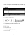
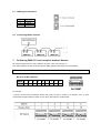
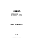
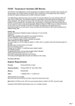
CODE
6 Channels Digital
Dimmer Pack
User’s Manual
CODE ELECTRONIC CO., LTD.
Welcome to use CODE DM66-S Digital Dimmer Pack. CODE DM66-S meets DMX-512/1990 standard digital
control signal. It is suited for using with a console that generates DMX-512/1990 control signal, thereby them
constitute a digital light dimming control system. DM66-S’s EMI is very low. So greatly, it is used for light dimming
in TV studios, theatres, troupes, danceries, etc.
1.
Specifications
Dimming Channel:
6 Channels (30A max. per channel )
Control Signal:
DMX-512/1990 standard digital signal
EMI Restraining:
High efficiency EMI Choke
Cooling:
Fan
Channel Protecting:
Miniature circuit breakers, 32Amps
Power Supply:
Three-phase/single-phase, 220V~, 50-60Hz
Standby Wasting:
27 Watts approx
Volume:
482mm (W) x 133mm(H) x 455mm(D) (19”standard, 3U)
Weight:
17.6kg
2.
Front Panel And Rear Panel Devices
1.
DIP encoder (setup DMX-512 inception address number/select data memory mode)
2.
DMX-512 signal input pilot light
3.
Channel output state pilot light
4.
Dimming + Keys (UP)
5.
Dimming – Keys (DOWN)
6.
Miniature circuit breakers For Channel Protecting
7.
Switch for operation power supply
8.
Fuse for operation power supply
9.
Connector for DMX-512 digital signal input, XLR-D3M
10. Connector for DMX-512 digital signal thru output, XLR-D3F
11. Terminals for 6-channel loads
12.
Terminals for power supply net input (3-phase 4-wire and earth)
1
CONNECTION & OPERATION
3. Contents Checking
One CODE DM66-S set and one User’s Manual in the package.
4.
Power Supply Connecting
This set is suitable to three-phase or single-phase
Power supply.
4.1
Single-Phase Power Supply Connecting
Connect the “live wire” of single-phase power
supply to “L1”, “L2” and “L3” all together;
connect the “neutral wire” to “NE”; and
connect the “safe earth” to “GND”.
4.2
Three-Phase Power Supply Connecting
Connect the “A/B/C live wires” of three-phase
power supply to “L1”, “L2” and “L3” respectively;
connect the “neutral wire” to “NE”; and
connect the “safe earth” to “GND”.
5. Loads Connecting
Connect the “live wire” of every circuit to the output terminal of CODE DM66-S respectively; connect the “neutral
wires” of the circuits to “NE” terminals of this set. The connection mode is showed as follow sketch map.
6. Connecting With A Console
CODE DM66-S Digital Dimmer Pack can be controlled by a console that generates DMX-512 digital signal. The
control signal connection mode is showed as follow sketch maps:
2
6.1
DMX signal connectors
Pin No.
1
2
3
Connection
GND
Signal Signal +
6.2
Connecting With A Console
7.
Confirming DMX-512 Local Inception Address Number
DIP switch’s position function: “ON”, obtains its bit value; “OFF”, its bit value is “0”.
The relation between bit value of DIP encoder and DMX channel code keeps to the formula below:
[ The sum value of 1~9bit switches of DIP encoder ] + 1 = DMX inception address number
001
002
004
008
016
032
064
128
256
B/A
Bit value of DIP switches
DIP bit
1
2
3
4
5
6
7
8
9
Value
1
2
4
8
16
32
64
128
256
ON
DIP
1 2 3 4 5 6 7 8 9 10
CH START
For example:
A console connects with four DM62-S dimmer sets. Every set ties up number of 6 channels. Thus, we must
confirm DMX inception address number of every set by DIP switches, as follow table:
3
8. Confirming Output State Memory Mode
Confirming the output state memory mode of CODE DM66-S by No.10bit switch of DIP encoder. When the
position of No.10bit switch is “A”(moved at downside), this set is in data memory state. It means of DMX-512
control signal broken off abruptly, the current output state of every channel is not changed. Whereas, the position
of No.10bit switch is “B”(moved at upside), the data memory function is closured. It means of DMX-512 control
signal broken off abruptly, then every channel outputs zero.
9.
operation power Supply Switch ( “POWER” )
This switch turns on or turns off the operation power supply which powers for MPU unit of CODE DM66-S Digital
dimmer pack.
(I: turn on, O: turn off)
When the switch is turned off, the inner thyristor circuits are lived all the same. In this time, do not open the casing
of the set for preventing electric shock!
10.
DMX-512 Signal Input Pilot Light ( “SIGNAL” )
The pilot light is twinkling while receiving normal DMX-512 signal. Otherwise, it is blank.
While it is blank, please check the console, the cable, the connectors, the polarity of DMX512 signal.
11.
Channel Output State Pilot Light
The brightness of every pilot light denotes its channel output intensity.
12. Output Circuit Protecting
A Miniature circuit breakers is in every output circuit of CODE DM66-S. Every switch is 32Amps. While the output
over-current or the output terminals be short-circuit, the switch will cut off immediately for protecting this channel.
13. Independent Dimming Function
Every channel can dim the lamps independently by UP/DOWN keys without any console.
14.
The Set Running
Connecting and setting up DM66-S dimmer correctly, turning on the operation power supply of the console and
this set, then system starts running. We may change the local inception address number and/or output state
memory mode by DIP switches at any moment.
4
M E M O
5