1
CONTROL PANEL
CA-64
(software version 1.03.xx)
User’s manual
Przedsiębiorstwo Produkcyjno-Usługowe
®
GDAŃSK
ca64u_e 06/01
USER’S MANUAL
CONTROL PANEL
CA-64
Przedsiębiorstwo Produkcyjno Usługowe
SATEL s.c.
June
2001
GDAŃSK
POLAND
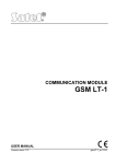
Thank you for choosing the product offered by us. High quality, large number of
functions and simple operation are main advantages of the control panel offered by
SATEL s.c.. Hoping that you will be fully satisfied with this choice, we declare to
provide you with professional assistance and information on our products. We would
like to inform that, besides control panels, SATEL s.c. produces many other
components of alarm system. Look for detailed information on our full offer in retail
outlets dealing with our products, at our website www.satel.pl or directly at out site, tel:
(58) 32 09 410; fax (58) 32 09 401.
We kindly ask you to read the entire Manual carefully, since detailed knowledge on
the control panel functions will allow you to fully utilise all included possibilities. This
Manual is very general, and deals with the basic operation of a typical alarm system
installation. The control panel may carry out functions that are nor related directly to
monitoring. We are not able to foresee all possible ways of use of all the control
panel functions available. The use of all control panel functions and efficiency of
operation of the entire system depend on the installation itself and the software
installed by the installer. The control panel may perform its functions in many ways,
which are defined when installing the system and its software. Due to the above, the
installer should give you more detailed information regarding the operation of the
alarm system and procedures of its using.
All situations, where the way of the control panel operation depends on previous
installer decisions (made at the time of programming), are additionally marked with
text in brackets: (service setting) (following the description of situation). The term
“service” used in this Manual relates to the user who maintains and takes care about
the alarm system and uses the service code (see page 12). It may be the installer,
maintenance person, the employee caring for protection of the object, etc.
ABOUT THIS MANUAL
This Manual describes the basic operation of modules used for controlling the system
operation, as well as the control panel functions.
The first part of this Manual, titled “Operation of Control Panel CA-64” contains
descriptions of modules used for controlling the operation of the control panel and
their way of use. Also some functions related to the alarm system operation are
described here. Furthermore included are the basic information on system
functioning and use of the telephone line by the control panel.
The second part of this Manual, titled “Description of user functions” contains full
specification of functions accessible from alphanumeric LCD keypad. Each function is
described in detail and shown in a block diagram.
The text in this Manual contains some technical terms, please, use APPENDIX C at
the end of Manual for explanation.
This Manual refers to the control panel program, version 1.03.12, and the
DLOAD64 installer’s program, version 1.03.15, up-to-date on the day of
preparation hereof.
2
User’s Manual
CA-64 SATEL
CONTENTS
INTRODUCTION................................................................................................................................................. 3
OPERATION OF CONTROL PANEL CA-64 .................................................................................................. 4
BASIC INFORMATION ................................................................................................................................... 4
LCD KEYPAD................................................................................................................................................... 6
THE USE OF LCD KEYPAD ........................................................................................................................... 7
PARTITION KEYPAD.................................................................................................................................... 10
CODE LOCK ................................................................................................................................................... 12
PROXIMITY CARD AND DALLAS CHIP READER................................................................................... 13
CODES AND USERS...................................................................................................................................... 14
SYSTEM ARMING ......................................................................................................................................... 15
ALARMS ......................................................................................................................................................... 17
MESSAGING ON ALARM BY TELEPHONE .............................................................................................. 17
ANSWERING PHONE CALLS ...................................................................................................................... 18
OTHER FUNCTIONS USING TELEPHONE LINE ...................................................................................... 19
DESCRIPTION OF USER FUNCTIONS ........................................................................................................ 20
MAIN MENU .................................................................................................................................................. 20
BLOCK DIAGRAMS AND DESCRIPTION OF USER FUNCTIONS ......................................................... 21
DISARMING................................................................................................................................................ 23
CLEAR ALARM ........................................................................................................................................... 23
CLEAR OTHER ALARMS ........................................................................................................................... 23
ABORT VOICE MESSAGING ..................................................................................................................... 23
ARM............................................................................................................................................................. 24
ARM (2 CODES) ......................................................................................................................................... 24
DISARM (2 CODES) ................................................................................................................................... 24
DEFER AUTO-ARM.................................................................................................................................... 24
SET AUTO-ARM DELAY ............................................................................................................................ 25
ARMING MODE ......................................................................................................................................... 26
CHANGE OWN CODE ............................................................................................................................... 26
MASTERS .................................................................................................................................................... 27
USERS ......................................................................................................................................................... 28
ZONE BYPASSES ........................................................................................................................................ 32
SET TIME .................................................................................................................................................... 32
FAILURES................................................................................................................................................... 33
EVENTS....................................................................................................................................................... 33
RESET ZONES ............................................................................................................................................ 35
CHANGE OPTIONS.................................................................................................................................... 35
TESTS .......................................................................................................................................................... 36
SERVICE ACCESS ...................................................................................................................................... 39
SERVICE MODE......................................................................................................................................... 39
SM TAKE-OVER ......................................................................................................................................... 40
DOWNLOADING ........................................................................................................................................ 40
SUMMARY ......................................................................................................................................................... 41
APPENDIX C – explanation of some technical terms ..................................................................................... 42
APPENDIX D – examples of keypad operation ............................................................................................... 43
APPENDIX E – functions of keys and lamps ................................................................................................... 50
Operation of control panel CA-64
3
INTRODUCTION
The control panel CA-64 is intended for controlling operation of alarm systems, which
monitor and supervise the security of medium-sized and large objects. Supervision is
not limited to protection against burglary, but may also include monitoring the correct
functioning of the object for 24 hours per day. The status of the alarm system is
monitored continuously. Violation of any alarm system component results in a so
called tampering alarm. The control panel responds to signals from individual
detectors and decides whether to activate alarm or not. Since various detectors may
be connected to the control panel, type and way of alarming depends on the control
panel software installed (the control panel may respond in a different way to a signal
from fire detector than to a signal from a water level detector).
The control panel allows grouping of detectors (zones) to obtain so called partitions,
as well as free choice in determination, which partition is to be monitored (armed).
Activation of any detector from such a group (called “zone violation” in the below text)
may trigger an alarm. High flexibility of the control panel in determination, which
partitions may be armed at the moment, is its great advantage.
BASIC FUNCTIONS OF THE CONTROL PANEL:
•
•
•
•
•
•
•
signalling burglary, attack, fire, technical and auxiliary alarms,
monitoring – communication with telephone monitoring stations (real time sending
detailed information on selected events in the protected object),
messaging on alarm by telephone – either with the use of a vocal message or to a
pager,
answering phone calls (this function is protected with a separate code) that makes
possible:
- to inform the user on a system status,
- to control some of the control panel functions via telephone; these functions
are programmed by the service,
real time printout of information on all or selected events occurred in the alarm
system,
supervision of access to rooms through doors provided with electromagnetic
locks,
monitoring the correctness of operation of individual alarm system components
(power supplies, batteries, wiring).
CONTROL PANEL USAGE PROPERTIES:
•
operation by means of keypads provided with LCD text display (2x16 characters)
to facilitate the use of the system,
• descriptions of zones and partitions defined by the installer make easy to find the
alarm source,
• visible date and time of the system clock allow controlling the correctness of
functions that depend on the real time,
• accessible are: viewing the alarm memory and failure memory (or detailed
memory of all events) with event description in words, zone, module and partition
4
•
•
•
•
•
User’s Manual
CA-64 SATEL
name or name of the user who operates the system, together with accurate time
of the event occurrence,
control and monitoring (up to) 8 independent alarm subsystems and (up to) 32
partitions armed independently,
control of individual system parts from independent keyboards (maximum 8 LCD
keypads and 64 partition LED keypads),
control and supervision of the system by means of a computer (program
GUARD64),
dynamically changing menu (dependent on access level) to provide access to a
range of user functions – the selection is made by accepting the function at the list
shown in the LCD keypad screen,
key short cuts to facilitate calling frequently used functions.
OPERATION OF CONTROL PANEL CA-64
BASIC INFORMATION
LCD keypads and partition keypads are used for operation of alarm system based
on control panel CA-64. Moreover, the control panel supervises and registers usage
of code locks and proximity card as well as Dallas chip readers, located adjacent
to doors in individual rooms of an object. Partition keypads may be also used as code
locks.
Individual control devices are assigned to selected partitions by the installer. LCD
keypads may operate many partitions of different subsystems. Partition LED keypads
operate a single partition only. Individual users may operate the control panel when
they are provided with access to partitions operated by specific keypads. That
means, the partitions assigned to the user at the stage of a new user creation or
edition (see Description of User Functions Æ Users) must correspond to partitions
operated by a keypad. The installer defines the list of partitions operated by individual
LCD keypads.
Example: A LCD keypad controls operation of partitions: 1,2,3,4,5 and 6. The user
has access to partitions: 5,6,7 and 8. It is seen from comparison, that by using this
LCD keypad the user may control operation of partitions 5 and 6.
A similar rule applies to partition LED keypads, code locks and proximity card
readers. With keypads, the user may control these partition to which he has access,
he may open these doors with code locks and proximity card (or DALLAS chip)
readers, for opening of which he has been authorized. The installer defines the list of
users of individual partition keypads, coded locks and proximity card readers
(separately for each module).
The access to functions controlling the operation of the control panel and more
important information on the system status are protected with a CODE (code –
combination of 4 to 8 digits). It is possibile to obtain some information on system and
call some functions without using a code (service setting) – by keeping depressed
one of the following keys for a longer time (approximately 3 seconds):
Operation of control panel CA-64
1
2
3
4
5
6
7
8
0
✶
#
5
– zones status viewing,
– keypad tampering viewing,
– expander tampering viewing,
– partitions status viewing,
– alarm memory viewing,
– failure memory viewing,
– current failure viewing,
– switching on / off gong signal in LCD keypad,
– auxiliary alarm (for example, calling medical aid),
– fire alarm,
– attack alarm.
Functions of keys from 1 to 8 are accessible from LCD keypad only, and other
functions may be accessible (service setting) from each keypad installed in the
system (LCD keypad, partition keypad, code lock). The functions called this way
provide information on all partitions operated with specific LCD keypads. Also, they
are accessible via the User Menu (see: Description of User Functions – Tests, Event
History, Failures, Change of Option), however, when called via the User Menu they
provide the information on partitions accessible for the individual user, who called
that function, only.
It is recommended that this way of calling functions be accessible in LCD keypads
fully protected against access of unauthorised persons.
An “attack alarm” (called by #) may be signalled externally, in a similar way to an
alarm of “burglary” type (buzzers, lights), it also may be arranged not to activate any
signalling and remain as a “silent alarm PANIC” (service setting).
Also, the installer may render accessible the function of quick arming of certain
partitions (so called QUICK ARM) to be called by pressing two keys: 0 and # in
sequence:
!
0#
quick arming of partitions. This function may be accessible from an
LCD keypad and a partition keypad. When called from an LCD
keypad, the function may arm several partitions, and when called from
a partition keypad, it may arm only this partition, to which the partition
keypad is assigned.
Moreover, keeping depressed the key marked Ó displays LCD keypad name, and
depressing two key: Ò and Ó (for approximately 40 seconds) causes the keypad
processor to restart and display the keypad software version number and the control
panel software version number.
6
User’s Manual
CA-64 SATEL
LCD KEYPAD
1
2
3
4
5
6
7
8
9
10
11
12
13
14
15
16
CA-64
1.03.12
<c> 2001 Satel
17
18
19
20
21 22
23
24
25
26
27
28 29
30
31
32
CONTROL PANEL
CA-64
1
2
3
4
5
6
7
8
9
*
0
#
ALARM
FAILURE
ARMED
SERWICE
1-32
ZONES
1-64
33-64
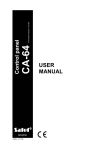
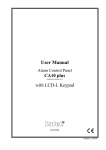
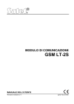
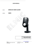
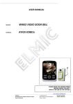
Figure 1
An LCD keypad is provided with a large LCD display (2 x 16 characters) with
permanent or temporary backlighting, the latter is activated either by pressing any
key or by violation of any zone (service setting).
16 keys (lighted similarly to the keypad screen) are located beneath the display,
which are used for:
entering the code,
moving along menu and selecting appropriate functions from the list,
entering data for functions called.
Six LEDs are located at the right-hand side of the display to indicate current system
status.
•
•
•
•
ALARM (red) – continuous light informs on alarm signalling activation at this
moment. When the LED blinks, it means that, in partitions operated with this
keypad alarm signalling occurred again since the last reset of the alarm memory.
FAILURE (yellow) – the LED blinking informs on presence of a technical problem
in the system. Failures, which activate this LED, are described further in this
Manual (see Description of User Functions Æ Failures).
The LED does not light when the LCD keypad operates in partially armed mode
(at least one partition accessible for the LCD keypad is armed) or armed mode (
all partitions accessible for the LCD keypad are armed) (service setting).
ARMED (green) - the LED blinks when some partitions are armed and lights
steadily when all partitions operated by the keypad are armed.
SERVICE (green) - the LED blinks when the control panel operated in the service
mode (function accessible for the user provided with the service code only).
Note:
Service mode limits normal operation of the control panel. Alarms from most
of zones (except for zones of the following types: attack, cash point, and
vibrating) and tampering alarms are not signalled. In order to restore the
normal control panel operation mode, just exit the service mode, for the
control panel does not return to its normal operation mode automatically.
Operation of control panel CA-64
•
7
Zones 1-64 (two green LEDs) – they are used when viewing and testing status of
zones and “expander” type modules – they indicate which group of zones (or
which expander bus) is currently displayed on the LCD keypad screen (see
Description of User Functions Æ Tests).
In addition to visual signals, the LCD keypad may generate audible information
(service setting). The following signals, specific to some situations, may be heard
when using the keys:
One long beep - refusal of arming - the zone, which shouldn't be violated at the
time of arming, is violated (option - "PRIORITY"). The refusal includes all zones
selected for arming.
Two long beeps – the control panel did not recognise the code; function is not
accessible; erratic data; confirmation of abandoning the selected function (after
pressing ✶ on the keypad keyboard); the key pressed is not active.
Three long beeps – the code is recognised, but the called function is not
accessible (for example, temporary partition bypass is activated or the user has
no access to partitions operated from the keypad; the zone, which should not
be violated when being armed, is violated – refusal of arming).
Two short beeps – selection accepted – entering more detailed menu level.
Three short beeps – confirmation of arming or disarming.
Four short beeps and one long beep – acceptance of execution of the selected
function.
Three pairs of short beeps – it is necessary to change the code (for example,
another user, when changing his code, has given an identical combination of
digits as the combination in the code of the user; the code validity is expiring).
Moreover, the installer may program audible signalling in an LCD keypad for the
following situations:
Alarm for a partition – continuous sound for the total alarm duration (time
programmed by service).
Fire alarm – series of long sounds every second for the total alarm duration.
Count down of time for entering – short sounds every 3 seconds.
Count down of time for exit – long sounds every 3 seconds, completed with
a series of short signals (for 10 seconds) and a single long sound. The way of
signalling of “time for exit” informs that the count-down is finishing.
Signaling the auto arming delay time countdown (timer-controlled partitions)
- a series of 7 sounds (of diminishing length).
Gong in the LCD keypad – five short sounds – this is a response to activation
of some detectors when the zone is disarmed.
THE USE OF LCD KEYPAD
Operation of the system from LCD keypad starts with entering the user CODE and
pressing the key marked # or ✶. Note that the control panel response (functions
accessible) after pressing the # key is different from that generated after pressing the
✶ one. The specific feature of the control is the dynamic changing of the accessible
menu, dependant on the system programmed parameters, as well as on the
authorisation level of the user who entered the code. The designers of the control
8
User’s Manual
CA-64 SATEL
panel have chosen such a way of its control to facilitate operation by users who do
not know the system very well. Also, taking into account the safety of the object, it is
not recommended that most of users have access to all control panel functions.
The system incorporates the hierarchy system for access to the control panel
functions and partitions defined for the object by the installer.
Generally, typing at the keyboard:
gives access to functions of arming/disarming type,
CODE #
!
gives access to all functions in the User Menu, to which the
CODE ✶
!
user is authorised
Note:
When an erratic code (not recognised by the control panel) is typed three
times, the alarm will be activated (service setting).
The list of the control panel functions for user access is formed in a dynamical way.
The contents of the list depends on system parameters, code type, user authorisation
and alarm system status and situation.
Example: When you type your code and press #, the control panel makes accessible
functions of partition arming (provided there are no partitions, operated from the
LCD keypad, already armed) or disarming (if any of partitions is armed). In the
event of alarm occurrance in the system, the control panel may cancel this alarm
and make accessible the function of partition disarming (if the user has
authorisation to do that). When the function of messaging by telephone is
activated – function Cancel messaging by telephone may appear in menu. When
the user has access to a single partition only, typing the code and pressing #
causes immediate arming or disarming (if the partition is armed).
Typing code and pressing ✶ causes that the list of functions accessible from the
User Menu is displayed. From this menu also the functions of the following type
may be accessed: arming and disarming (if some partitions are armed). When all
partitions are armed, the function Arm will not be accessible.
As you can see in the examples described above, the control panel, in an intelligent
way, makes accessible those functions only, which may be executed by a specific
user.
All user functions, which are accessible from LCD keypad, are described in
section”Description of User Functions”.
SELECTION OF FUNCTION
When the control panel accepts the code, the first user function (from all functions
accessible currently) appear in the upper line of the display. You can move through
the list of functions rendered accessible by the control panel by pressing key Ò and
Ó, and select the item in the list (single-selection list) by pressing the key # or Ñ. If
the selected function requires making further selection (submenu, options), the next
list appears on the display, from which you can select required item in a similar way.
Some functions may need selection of few items from the list (multi-selection list). To
do that, scroll the list by pressing Ò and Ó key and „mark” all items in the list, which
should be selected. The item is marked by pressing any numeric key, the symbol
appears in the upper display corner next to the text. Press the numeric key again to
cancel marking.
By scrolling the list upward or downwards (list contents is displayed in a cyclic way),
you can see all list items and check marking. Pressing the key # or Ñ accepts the
selection (execution of function may be confirmed with beeping), and the control
Operation of control panel CA-64
9
panel returns to previously displayed menu or displays the adequate message and
returns to the basic status (waiting for code). Then, current date and time is
displayed. Date and time display format is defined by the installer (service setting).
There is the control panel setting option, which activates the procedure of double
acceptance of some user functions. After pressing the key # or Ñ (normal way of
selection of function), the prompt appears on the screen asking to confirm the
function, together with information: 1 = Yes. Press the key with digit 1 to confirm this
function. This procedure protects against accidental double pressing the key # (or Ñ)
and execution of function, which should not be executed. The description of user
functions in this Manual relates to situation when this option is switched off.
If you want to abandon the selection of function after opening the User Menu, press
key ✶. In the event no keypad button is pressed (within 2 minutes) after menu
opening, the control panel automatically closes this menu and returns to its basic
status.
GRAPHICAL MODE
Partition selection functions allow also another way of multiple selection from the list
(for example, selection of partitions for arming). It is called a graphical mode. When
you have already entered the selection list, press key Ñ or Ð to enter this mode.
Dots under the number of each accessible partition (numbers 1 - 32 around the
display) appear on the keypad screen. The dash under the dot (cursor) indicates
which item may be marked. Use key Ñ and Ð to move the cursor to the item
to appear at the item
required. Pressing any numeric key causes the symbol
selected. Press the numeric key again to cancel marking. Press key Ò or Ó to
restore the previous way of display (with name).
ALARM SOURCE NAME READING
The installer may also render accessible the function of displaying the name of the
alarm source at the LCD keypad screen, without necessity of entering the code. In
such an event, the partition or zone name is displayed at the keypad screen, when
an alarm occurs. When there are few alarm causes, you may scroll zone names, for
which alarm occurred, and names of partitions, where the alarm is (or has been)
signalled. Arrow keys: Ð and Ñ allow viewing partition names (if an alarm occurred
for few partitions), and keys Ò and Ó allow viewing zone names, for which an alarm
occurred. These names (entered initially by the installer) are displayed in a cyclic way
in the lower display line, and they are shown in numeric order of zones (or partitions)
in the system. The information on alarm activation is stored in so called “temporary
alarm memory”, until the contents of this memory is cleared by an authorised user
(see “Description of User Functions” Æ Alarm clearing). The contents of this memory
may be checked many times after resetting the alarms, until it is deleted.
10
User’s Manual
CA-64 SATEL
PARTITION KEYPAD
ALARM
1
2
3
ARMED
FAILURE
4
5
6
7
8
9
0
#
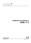
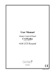
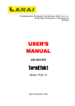
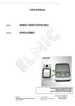
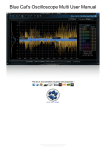
Figure 2
Partition keypad is provided with 12 keys with permanent or temporary backlighting
(service setting), and three LEDs described as follows:
• ALARM (red) – steady light indicates an alarm in the partition operated with this
partition keypad, and blinking indicates that alarm occurred in this partition earlier.
• ARMED (green) - steady light informs, that the partition assigned to this keypad
has been armed. The LED blinks when the time for exit is being counted down.
• FAILURE (yellow) – the LED blinks when a technical problem has been detected
in the system. Check the LCD keypad for the type of failure. Indication of this
LED relates to the entire system, not only to the partition operated with this
keypad. Arming of a partition switches off the LED, and disarming causes the LED
to lit again.
When all of three LEDs (ALARM, ARMED, FAILURE) flash in sequence, this
indicates missing communication between the keypad and the control panel. This
situation may occur when program STARTER runs in the control panel or the cable
connecting the partition keypad to the control panel is damaged.
There is a possibility to program a partition to be armed or disarmed after entering
two codes (service setting). In this event after entering the first code, LEDs ARMED
and FAILURE start to blink, and the control panel waits for entering the second code.
Similarly to the LCD keypad, the partition keypad may generate audible signals. This
way the control panel confirms the function called, since there is no display at the
partition keypad.
One long beep - refusal of arming - the zone , which shouldn't be violated at
the time of arming, is violated (option - "PRIORITY").
Two long beeps – the code is not known to the control panel.
Two short beeps – acceptance of the first of two codes needed to arm or
disarm.
Three long beeps – the code cannot control this partition.
Three short beeps – confirmation of partition arming and disarming.
Three pairs of short beeps – it is necessary to change the code - for example,
a user, when changing his code, has entered an identical combination of digits
as in the code of another user, or end of code validity is approaching.
11
Operation of control panel CA-64
Four short beeps and one long beep – the confirmation of the performance of
acontrol function, code change and of a guard round.
Five short beeps - the dependent door are open - the door control has not been
performed. To operate the lock it is necessary to close the dependent door and
reenter the code.
Blinking of the back-lit may substitute the audible signalling (service setting). Beeps
correspond to keypad lighting off pulses, when the lighting is on, or light on pulses,
when normally it is off.
Also, the partition keypad may indicate alarm occurrence in the partition concerned
(service setting).
Alarm in the partition – steady sound for total alarm duration.
Alarm memory – long sounds every two seconds until alarm is reset. The
sounds are synchronised with ALARM LED flashing. Press any numeric key to
silent the sounds for approximately 40 seconds.
Fire alarm – a series of long sounds every second for total alarm duration.
Fire alarm memory – short sounds every two seconds until alarm is reset.
The sounds are synchronised with ALARM LED blinking. Press any numeric
key for approximately 40 seconds to silent the sounds.
Count down of time for entering – short sounds every 3 seconds.
Signaling the auto arming delay time countdown (timer-controlled partitions)
- a series of 7 sounds (of diminishing length).
Door are open for too long - short beeps repeated with high frequency till
the door are closed (the function of door control is activated).
Operation of the system from the partition keypad is very limited, and it relates to the
partition, to which the keypad has been assigned by the installer. There is a
possibility to operate an electromagnetic door lock from the partition keypad by
means of the user’s code. Several partition keypads may be assigned to a single
partition.
Functions accessible from the keypad are as follows:
!
!
CODE #
CODE ✶
arming and disarming of partition and alarm reset.
electromagnetic door lock opening.
Similarly to the LCD keypad, the user, who wants to start functions mentioned above,
need to have access to the partition concerned and proper authorisation. Besides, he
need to be authorised to use the partition keypad concerned (these rights are
assigned by the administrator with in the GUARD64 program, or the installer (service)
in the DLOAD64 program).
When the erratic code is typed three times, the alarm may be activated (service
setting).
Other functions accessible from the partition keypad (without code entering) are as
follows:
quick partition arming,
0#
!
and functions of calling special alarms:
panic alarm,
#
auxiliary alarm (calling for medical aid),
0
fire alarm.
✶
The last three functions are started by longer keeping depressed (for approximately 3
seconds) the key described above.
12
User’s Manual
Note:
CA-64 SATEL
When arming is on for the partition, and the partition keypad also controls
the electromagnetic door lock, typing: CODE ✶ causes disarming and door
opening – if the partition is not bypassed temporarily. However, If the user
has no authorisation for disarming, the door remains closed.
Code change by the user is another, additional partition keypad function (service
setting). User partition change is carried out as follows:
Press and keep depressed (for approximately 3 seconds) the key with digit
“1” (LEDs ALARM and ARMED – red and green – start to flash alternately).
Type the old CODE and press # (LEDs: ALARM and FAILURE – red and
yellow - start to flash alternately).
Type new CODE and press # (LEDs stop blinking and the module generates
confirmation signal of function execution).
In the following four cases the control panel cannot accept the change of code (it is
signalled with two long beeps):
1. the new code is too short or too long (accepteble are codes of lengthfrom 4 to
8 digits)
2. the new code is too simple ( the function of refusal of simple codes is
activated)
3. the new code is identical with a code of another user of the alarm system
(someone's code has been "guessed")
4. change of the code has been blocked, because another user "guessed"
thecode trying to change his own code. If the function of reminding about the
necessity of code change is activated, each usage of such a "guessed" code
will be signalled with three double beeps. In this event the change of the code
will be possible only by means of the LCD keypad with the requirement of
confirmation of the code change (see: the description of the function "change
own code") by the administrator of the subsystem. It makes impossible to
"take over" the code by a user who accidentally "guessed" the code.
NOTE: With a big number of users it is advisable to use longer codes, at least 5-digit
ones, to reduce the chance of "guessing" the code of another user.
CODE LOCK
The coded lock looks similarly to the partition keypad. The code lock is provided with
12-key backlit keypad. Keypad backlit may be permanent or temporary (service
setting). The lock is provided with three LEDs marked as follows:
•
•
•
STAND BY (green) – LED is on when the lock is operated by the control panel,
and the door may be open.
ACCESS (red) – LED is on when the door lock is being unlocked.
DOOR (yellow) – this LED shows the status of zone, which monitors the door
status. The LED is ON when the door is open.
When all three LEDs (STAND BY, ACCESS, DOOR) flash alternately, that means
there is no communication between the code lock and the control panel. This
situation may occur when program STARTER is running in the control panel or the
cable connecting the code lock keypad to the control panel is damaged.
Operation of control panel CA-64
13
The basic code lock function is to control the access to the room, where the door
provided with electric catch, bolt or electromagnetic interlock are installed. Also, the
lock may be used for partition checking when sentry round in the object.
To open the door, type CODE at the lock keypad and press key # or ✶. The user
must have access to use this code lock.
!
!
CODE #
CODE ✶
door opening
door locking
When an erratic code is typed three times, the alarm may be activated (service
setting).
It is possible to call special alarms using a code lock keypad. These three functions
are called by longer keeping depressed (for approximately 3 seconds) the key:
panic alarm,
#
auxiliary alarm (calling for medical aid),
0
fire alarm.
✶
Confirmation of the function called by the control panel (with sound or blinking) is
identical as for partition keypad.
PROXIMITY CARD AND DALLAS CHIP READER
Proximity card and DALLAS chip readers have the same role to play in the system as
code locks. Proximity card readers are provided with two-colour LED and buzzer for
communication of the control panel with the user. DALLAS chip heads are not
provided with any signalling of this type, but the installer has a possibility to provide
such an external signalling.
Each alarm system CA-64 user (administrator, sentry, ordinary user) may be
assigned with one proximity card and/or DALLAS chip at the stage of user creation or
edition. Also, it is possible to remove the previously assigned card (chip) to a user
from the control panel memory. In order to provide a new user with a card (chip) with
a code already known to the control panel, first remove this card (chip) from memory
(see: USER MANUAL, CA-64 → Description of user functions → Users), and then
assign it to another user.
Use the card as follows: bring the card close to the card reader and hold it there for
approximately 0.5 sec. The distance between the card and reader, when reading,
may be up to 12 - 14 centimetres, depending on reading head type. DALLAS chip
should be pushed into the head slot to close the zone electric circuit. The control
panel receives the code from the expander operating the reading head, recognises
the user, to whom the card (or chip) is assigned, and operates according to settings
programmed, when the user has authorisation to open the door (to activate the
relay).
In the alarm system CA-64, the proximity card reader signals have the following
meaning (DALLAS head may generate identical signals):
♦ Meaning of audible signals generated after proximity card readout:
single short beep – card code readout,
Two short beeps – start of card code writing function, confirmation of first
writing,
Two long beeps – control panel have not recognised the card,
Three long beeps – card code is recognised, but the user has no access to
the lock (relay control),
14
User’s Manual
CA-64 SATEL
Four short beeps and one long beep – card code accepted, the relay
activation, second correct readout of a new user card,
Five short beeps – dependent door open (relay has not been activated).
Short beeps (without time limitation) – door opened for a too long period.
♦ Meaning of visual signals emitted during armed status and after proximity card
code readout:
LED blinks red in a uniform way – missing communication with control panel
(this situation may occur when the special system initialisation program
STARTER is running in the control panel, the reader module has not been
identified or the cable connecting the module to the control panel is damaged.)
LED lights red steadily – module is correct, lock operation (relay control) is
possible.
LED changes colour from red to green once a second:
àsingle short changes – waiting for first card reading,
àdouble short changes – waiting for second reading of a new card.
♦ The installer may activate the option of confirming with a LED the messages sent
from the control panel to the user. In this case, after the card is read, the change
of LED colour from red to green goes on in accordance with audible signalling
described above.
CODES AND USERS
The functions of control panel operation is possible after entering a proper code and
pressing key ✶ or #. Three basic code types are used:
1) Service code – this code identifies the user with special rights: he controls all
partitions, he may open all doors controlled by the control panel, he has access to
most of control panel functions (except for the “Service access” and “Users”
functions – see Description of User Functions), he may enter and delete
subsystem administrators. Factory programmed service code : 12345.
2) Administrator (supervisor) code – this code identifies the user with highest
authorisation for subsystem. The administrator has access to all partitions within
his subsystem. There is a function which unlocks the service access (see
Description of User Functions – Service access level). This function is always
accessible for the administrator and not for the service. Factory programmed
administrator code for a first subsystem: 1111.
Other administrator rights may be limited by the service (installer). If few
subsystems are defined in the system, each subsystem has its own administrator
code. This user has the right to enter new users into the system.
3) User code – the remaining codes entered to the system by administrators or
users (with rights to edit the user). These are the codes for everyday operation of
the system. 192 user codes may be entered in the CA-64 control panel.
Operation of control panel CA-64
15
Notes:
♦ Service code is rejected by the control panel, when service access is locked. The
administrator may unlock the service access to the alarm system by using the
function „Service access” (see: Description of the User functions).
♦ If there is no administrator code in the system (all administrators are removed),
service access to the system is unlimited.
♦ It is recommended not to use the administrator code everyday (unauthorised
persons may peep the code). The administrator should enter an ordinary user
code, with “strategic” functions blocked, and he should use it in everyday work.
Protection of access to the service mode and prevention of entering codes by
unauthorised persons are main purposes of that.
An additional possibility is to assign specific control function to a code. This function
will be executed after the code is followed with the # key (see: Description of User
functions - Users).
The installer (using the service code) defines administrator codes and names (one
administrator per each subsystem), as well as he defines their rights.
The administrator has the right to enter ordinary system users. He provides them with
rights, type and defines the partitions, to which the users will have access. Also, the
ordinary user may have the right to enter other users. New user may have access to
these functions and partitions only, to which the user, who enters the new code has
access.
Note:
If the user has authorisation for changing the code, he should change it
after first usage of the code. The control panel reminds by means of a
message on the keypad display and an audible signal that this operation
should be performed (service setting).
The system stores the sequence order of entering users into memory. The person
with authorisation to enter and delete the users may remove from the memory the
users entered by him/her or his/her subordinates only. The service has the right to
edit all administrators (as well as to change codes). The administrator has such rights
for users in his/her subsystem. Ordinary users have rights to edit the users they
entered. This possibility is convenient when the code is lost. The supervisor of the
user concerned may enter a new code and make controlling the system available for
him (of course, within the range limited by his authorisation).
The control panel assigns numbers to the users to identify them in the system. This
number is used in messages transmitted to the monitoring station and in event
descriptions (see: Description of User functions – Event history).
SYSTEM ARMING
“Armed” is the basic status, for which the control panel was designed. In this mode,
the control panel detectors monitor the protected object, and any violation of the
protected partition is signalled by the control panel with all means accessible
(programmed by the installer). Control panel CA-64 enables individual control of
armed status in each partition. A single partition, several partitions and all partitions
may be in armed status. Each partition may be disarmed individually (by means of
partition keypad, LCD keypad) or totally (LCD keypad).
16
User’s Manual
CA-64 SATEL
Typing the following at the keypad is a normal way of arming:
partition keypad arms a single partition, and keypad gives the
! CODE #
possibility to arm all (or selected) partitions accessible.
quick arming – the partition keypad arms a single partition, and
! 0 #
keypad arms partitions programmed by the installer (no selection
possible).
If one of partitions accessible for the user is already armed, he/she may arm other
partitions when he/she types at the keypad:
! CODE ✶ arming by selecting „arm” from the function menu (see:
Description of User functions).
There are some special methods of system arming possible in a partition
(available from the LCD keypad):
- activate without internal zones – the control panel does not respond to
violation of zones defined as internal by the installer. This possibility allows
user to stay in the object and arm. The object is protected externally in normal
way, and the system performs all functions programmed.
- arm without delayed zones – arming is performed in a way similar to the
previous case, but additionally the delayed zones act as immediate ones.
To arm the system in one of the presented modes, proceed as follows:
1. Enter ACCESS CODE and press the ✶ key.
2. Call the „Arming mode” function.
3. Using the Ò and Ó keys select one of the suggested arming modes and press
#.
4. Call the „Arm” function and select (highlight) the partition to be armed.
5. Press the # key.
Disarming the partition will cancel the special mode of its arming. To re-arm the
partition in a special mode, the procedure described above must be repeated.
The procedure of arming the system from a LCD keypad in the partition where the
type (10) „24h vibration” zone belongs and the testing function of vibration sensors
is activated (service setting) is slightly different.
When the arming function (access code # or quick arming 0#) is called, the following
message appears on the LCD display:
„Vibration sensors test xx s (1 = arm)” where the xx field indicates the number of
seconds before the end of test.
During the test, the control panel is waiting for the violation of vibration zones in
a given partition. If all the vibration zones of the given zone are violated, the alarm
control panel switches over to counting the exit delay time and arming the system. In
case some of the vibration zones are not violated during this time, the control panel
will display a list of faulty zones (number and name of zone) and will not arm the
system.
Operation of control panel CA-64
17
Pressing the digit 1 key during the process of countdown will interrupt the test and
arm the system in normal mode, while pressing the ✶ key will make it possible to
cancel the arming.
Arming the system from the partition keypad will bypass the testing of vibration
sensors in the particular partition.
Also, special control ways of partition status are possible
• partition arming and disarming by means of timers. Timer is an internal control
panel logic unit, which measures time. Timer operation is programmed by the
service.
• partition arming and disarming by means of a “partition user timer”. This timer
may be programmed by the user, without necessity of asking the installer (or the
service) for that. There is a single timer of this type for a partition, this timer may
be programmed in daily or weekly cycle (see: Description of User functions →
Change of option).
• partition arming control by means of a special zone programmed (by the installer)
as arming control zone. In practice, it may be a mechanical switch; key switch,
pushbutton, radio switch. Also, such a zone may be controlled via telephone –
with the use of DTMF system (see: Answering phone call).
ALARMS
The system may signal alarms as the response for various situations occurred in the
protected object. Basic control panel alarms are as follows:
• Burglary alarm – activated when the zone is violated in the partition where arming
is on. The violation of the “delayed zone” starts to count down the delay time, after
which alarm is activated if the partition will not be disarmed.
• Fire alarm – activated by fire detectors, from keypad or in another way (for
example, pressing the pushbutton).
• Tampering alarm – activated by violation of any anti-tampering contacts in the
alarm system (located in detector and module casings), damage to cable(s), etc.
• Attack alarm – activated from keypad or in another way defined by the installer
(for example - pushbutton).
• Auxiliary alarm – activated from keypad (for example, call for medical aid) or in
another way defined by the installer (for example - remote controller or
pushbutton).
• Technical alarm – activated by various specialist detectors.
The way of signallisation of individual alarms may be different, and it is defined by the
system installer. It may be an alarm buzzer, information to a monitoring station, visual
alarm, audible alarm and (or) keypad message, telephone message, activation of
other external devices.
MESSAGING ON ALARM BY TELEPHONE
The telephone communicator integrated in the control panel CA-64 allows
transmission of information on alarm through the telephone line to any telephone
number. The message transmitted may be adapted to the alarm type (the system
18
User’s Manual
CA-64 SATEL
installer may install voice synthesizers to allow up to 16 messages to be replayed)
The installer defines, who and on which alarm will be informed by the control panel,
by programming relevant telephone numbers and defining rules of messaging.
Also, the control panel may transmit the information on missing 220 V power supply
in the form of voice message (or pager message). Power supply failure is a serious
danger for the protected object and the alarm system, therefore, this information has
been recognised as equally important as information on alarms.
The person, whom the control panel calls, may confirm message receipt. Special
code is used for that, programmed (by the installer) individually for each telephone
number. When the message is not confirmed, the control panel may repeat the
message transmission (number of repetitions is programmed by the installer). The
telephone set must be set to the DTMF tone dialling.
If the code is not correct, the control panel signals that with two long beeps. Correct
code is confirmed by four short and one long beeps.
When, instead of sounds described above, you hear a single short beep every three
seconds, the code is correct, but you must wait, because there are several messages
about different alarms.
If you make a mistake when entering the code, press any numeric key to supplement
the code to four digits (then the control panel signals erratic code), and next enter the
correct code.
Note:
The control panel analyses telephone signals in order to recognise whether
the phone call is answered. Therefore, it may occur that you will hear the
message after few seconds (up to 4 seconds) from picking the earphone.
This effect is not an error – it results from phone call confirmation signal.
When you say „halo...” to the earphone, the message will be communicated
immediately.
ANSWERING PHONE CALLS
The control panel CA-64 is able to answer phone calls and communicate information
on the system status. Also, you may call control functions with the use of telephone.
Each ordinary user may (at the stage of user entering or edition) be assigned with a
telephone code (do not mix this code with the code for confirmation of receipt of a
telephone message on alarm). The control panel recognises the system user with
this code and passes an information on partition status (armed, alarms) for partitions
accessible for this user. Also, the user may control the status of control panel relay
outputs programmed as „telephone relays”. The installer has a possibility to program
up to 16 telephone relays. Also, the installer decides which relays may be controlled
by individual users. To use this function of the control panel, you must have the
telephone set operating in DTMF tone system.
Note:
Not all cellular telephones allow control in DTMF tone system.
How to use this function:
Dial the telephone number (line) of the control panel. The way of dialling is
defined by the installer. The control panel may communicate after a defined
number of dialling signals (rings). Dialling may be single or double. When
double dialling is used, wait a defined number of “rings”, put the handset off,
and then dial the control panel telephone number again. After the number is
dialled the second time, the control panel should answer immediately.
Operation of control panel CA-64
19
After the communication is started, the control panel is ready to receive the
user telephone code – three short beeps (prompt).
Type code at the telephone set keypad (in the tone system). The control panel
accepts the correct code with series of beeps: four short and a single long one.
An incorrect code is followed with two long beeps.
Now the control panel operates in the mode of informing on partition status. It
waits for user’s response for 15 seconds and generates one short beep every
two seconds. Now It is required to enter the partition number at the telephone
set keypad (two digits – for example, 01; 05; 12; 25). If the user does not
respond within this time, the control panel will ring off.
After the partition number is entered, the control panel generates the message.
Three short beeps inform that the partition is disarmed and four short and one
long beeps mean that the partition is armed.
Alarm memory is an additional information given by the control panel. If an
alarm occurred in the partition, the control panel generates series of double
beeps – first is lower and second is higher – following the information on the
partition status. Where no alarm occurred, the control panel generates single
short beep every two seconds.
In order to move to the control mode of the telephone relays status, press 2 and #
at the telephone set keypad.
Now the control panel waits for the relay number (two digits). To trigger the
relay status to the reverse one, type the relay number at the telephone set
keypad. Two short beeps mean that the relay has been switched off and four
short beeps and one long beep mean that the relay has been switched on.
Each time you type the relay number, you change its status to the reverse one.
You may move back to the partition status indication mode by pressing keys 1 and
# one after one.
When you press keys 0 and # one by one, you exit the function and terminates the
phone call.
OTHER FUNCTIONS USING TELEPHONE LINE
If the alarm system uses functions of the control panel telephone communicator, the
line from the local exchange to the object is connected directly to the control panel,
and all telephone sets are located downstream the control panel. Therefore, no
signals are heard in telephone sets, when the control panel uses the telephone line.
This situation may occur frequently in multi-partition system, where monitoring is
activated. Moreover, the control panel will disconnect the telephone conversation,
when taking over the telephone line in order to transmit an information on a new
event. It should be said that control panel phone calls do not last for a long time (from
several to tens seconds, depending on the selected format data transmission).
Another function, where the control panel occupies the telephone line, is
programming by the telephone (“downloading”). This function may be initiated by the
service. The telephone line may be occupied for a long time, when data are
transmitted. Even if the programming is initiated by the user, the service may hold
communication with the control panel for cost saving reasons, and then restore it
without engaging the user.
20
User’s Manual
Note:
CA-64 SATEL
Access to the control panel in programming mode by telephone is protected
with ten-byte code (more than 1.2x1024 combinations). This is a very good
protection against hacking to the control panel by telephone aiming to block
it. Additionally, three sequential trials to call programming from outside
block the mechanism of answering to modem signals for 30 minutes.
DESCRIPTION OF USER FUNCTIONS
MAIN MENU
The list of functions accessible from LCD keypad is shown in Table 1. First table
column contains names of functions, and specific function properties are given in the
second column. There are functions accessible for the service only, and one function
is accessible for the administrator only. The functions are described by means of
block diagrams (see Figures below). Function names are extended with function
properties, as in Table 1.
Some functions are present in the menu alternately, only one of such functions – for
example, Service mode and SM take-over – is accessible at the moment. Pairs of
functions of this type are marked with a bold line section (at the left-hand side) – part
of table frame, function name column.
Symbols in column PROPERTIES (table 1):
- function has submenu
Õ
- multi-selection function
- function requires data to be entered (code , name, time)
xxx
- graphical mode of zone, partition and module information display is
graph
accessible
- function accessible for the service only
service
- function accessible for the master (administrator) only
master
21
Description of user functions
FUNCTION NAME
Disarm
Clear alarm
Clear other alarms
Abort voice messaging
Arm
Arm (2 codes)
Disarm (2 codes)
Defer auto-arm
Set auto-arm delay
Arming mode
Change own code
Masters
Users
Zone bypasses
Set time
Failures
Events
Reset zones
Change options
Tests
Service access
Service mode
Take SM (service mode) over
Downloading
Table 1
PROPERTIES
graph
Õ
Õ
Õ
Õ
Õ
Õ
Õ
graph
xxx
xxx
xxx
xxx
xxx
Õ xxx
Õ xxx
Õ xxx
xxx
Õ
Õ xxx
Õ
Õ xxx
xxx
Õ
Õ
Õ
service
graph
graph
graph
master
service
service
BLOCK DIAGRAMS AND DESCRIPTION OF USER FUNCTIONS
User functions are shown in block diagrams. The texts, which appear on the LCD
keypad display, or name of list accessible in the form of menu for scrolling, are
shown in frames. The list is scrolled by means of keys: Ò and Ó. The function, which
may be selected, is marked with arrow at the left-hand side of the function name (on
the keypad display) (ÉFunction name). Press key # or Ñ to move to the next block
in the diagram (function execution stage) according to direction shown with arrows.
The return from some menu levels to previous menu level is possible by pressing the
key marked Ð. Pressing the key ✶ at each menu level means (mostly) abandoning
execution of the function selected and return to the main menu. The user must be
authorised to use the function to make it displayed by the control panel.
Execution of each function is confirmed with proper message, which is shown with a
symbol at the block diagrams describing functions:
K
- end of function execution – the control panel displays a proper voice
message and returns to the basic status.
22
Usre’s Manual
CA-64 SATEL
DATA ENTERING
Some functions require typing of a new code or a user name. The way of entering
new data that relate to system users is described below. When changing the code,
the control panel does not show the old code, unless the user has not changed the
code assigned for him by the person introducing him to the system yet. But the old
name always is shown on the display when changing the old name. The user name
entered appears in selection lists, printouts and when viewing the event memory in
the computer.
• new code, time limit: numeric data are entered by means of numeric keys.
Arrow keys are used for modification of numbers being entered. Below the text
field, where digits entered appear, the cursor (dash) is seen. Arrows: Ð and Ñ
are used for moving the cursor to show digits in sequence. Press the key with
digit to enter the digit required at the left side of cursor, and press the arrow Ò
to delete the digit at the left side of cursor. The arrow Ó change cursor type –
blinking, dark rectangle appears. Cursor of this type allows changing the digit
above the dash to the digit typed at the keyboard. Press key Ó again to return
to the previous cursor type.
• user name: user name is entered by means of numeric keys, which change
their meaning and allow entering text data (letters) to the control panel. Table 2
contains characters accessible at the keypad keyboard. Subsequent pressing
of the key with a digit changes the characters in a cyclic way. The new user is
entered by changing the factory-entered name. You may delete the old name
by pressing the arrow key Ò (each single pressing deletes a character at the
left side of the cursor). Press arrow key Ó to enter space at the left side of the
cursor; use arrow keys Ð and Ñ to move the cursor under the user name
backlighting the position to be changed. To change the character at the
position indicated by the cursor, repeat pressing the key with the proper digit so
many times, until the proper character appears. Then, move cursor to the next
position and repeat the procedure.
Pressing # accepts data entered.
1
2
3
4
5
6
7
8
9
0
!
A
D
G
J
M
P
T
W
?
a
d
g
j
m
p
t
w
.
'
Ą
E
H
K
N
Q
U
X
,
`
ą
e
h
k
n
q
u
x
:
B
Ę
I
L
Ń
R
V
Y
;
"
b
ę
i
l
ń
r
v
y
+
{
C
F
4
Ł
O
S
8
Z
-
}
c
f
$ %
Ć ć
3
ł
o
s
5
Ó ó
Ś ś
6
7
z
✶
Ź
/
Ż
_
ź
=
& @
2
ż
<
\
^
│
9
>
(
)
Table 2 Characters accessible for the text mode of data entering.
[
#
1
]
0
23
Description of user functions
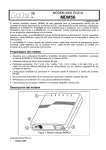
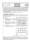
DISARMING
The function allows disarming in a single partition, several partitions selected or all
partitions accessible to the user, from a specific keypad.
select
code #
code ✶
Disarm all
Disarm selected
K
mark selected
What to disarm:
Partition name
Õ
graph
Disarm
Figure 3
CLEAR ALARM
The function clears alarm signalling and clears memory of alarms occurred since the
last alarm memory clearing. Alarm memory clearing does not include the event
memory, where the facts of alarm occurrence and cancelling are registered and kept
fully described. The function is executed automatically (when the system is armed
and alarm occurs) after the code is entered and key # is pressed. Then, the control
panel displays the menu of the function Disarm, and, after this function is executed, it
displays an adequate message.
code ✶
Clear alarm
K
Figure 4
CLEAR OTHER ALARMS
The function allows cancelling alarms from other subsystems, to which normally the
user has no access.
code ✶
Clear other al.
K
Figure 5
ABORT VOICE MESSAGING
When this function is called, messaging by telephone is stopped - the control panel
should ring off. If the telephone line is still occupied, that means, that messaging for
the partition non-accessible for a given user is carried out.
Messaging by telephone may be cancelled automatically together with an alarm
clearing (service setting).
Note:
If the installer has not specified the partition for a selected telephone
number, the users of which can cancel messaging by telephone, the
procedure of messaging by telephone to this phone number will be carried
out till the end, without possibility of stopping it.
code ✶
Figure 6
Abort voice m.
K
24
Usre’s Manual
CA-64 SATEL
ARM
The function allows arming of a single partition, few partitions selected or all partitions
accessible to the user.
select
code #
code ✶
Arm all
Arm selected
K
mark selected
Õ
graph
What to arm:
partition name
Arm
Figure 7
ARM (2 CODES)
The function arms special partitions. Two different codes must be used to arm them.
The presence of such partitions is declared (programmed) by the installer. The
second code must be entered within 40 seconds after entering the first one; after that
time the control panel returns to the basic menu.
select partition
code ✶
Arm (2 codes)
Partition name
Õ
type code
Enter the
second code
xxx
K
Figure 8
DISARM (2 CODES)
The function disarms in special partitions. Two different codes must be used to
disarm them. The presence of such partitions is declared (programmed) by the
installer. The second code must be entered within 40 seconds after entering the first
one; after that time the control panel returns to the basic menu.
select partition
code ✶
Disarm (2 codes)
Partition name
Õ
type code
Enter the
second code
xxx
K
Figure 9
DEFER AUTO-ARM
The function puts off (delays) the arming of a timer-controlled partition (auto-arming).
It is intended for programming the value of time interval by which the moment of
automatic arming of a partition is to be delayed. The maximum postponement time
value is 4 hours, 33 minutes and 3 seconds. Entering a higher value will set the
maximum permissible value, while entering the zeros alone will cancel the timer-
25
Description of user functions
controlled arming until the particular timer is activated again. Operation of this
function pertains both to the „Partition user timer” and the „Timers” programmed by
the installer.
The function makes it possible to select the partitions, where the countdown of
the „auto-arming delay” has begun. This very feature distinguishes the said
function from the described below user function „Set arming postponement”, which
gives access to all the partitions armed automatically with time delay which are
available to the individual user. In view of a low value of the auto-arming time (max.
255 seconds), it is important that a quick option of the partition arming postponement
be available in case it is necessary to stay inside.
Upon commencement of the countdown, the control panel presents on the LCD
keypad display the partition name and the delay time which remaines to arming. If the
time is simultaneously counted in a few partitions, the display shows the name of the
partition which will be armed first.
The postponement time is programmed individually for each partition for which the
auto-arming delay countdown has begun.
select partition
code ✶
Defer auto-arm
ÆPartitio
name n
Partitio name m
Õ
n,m – numbers of automatically controlled
partitions
enter time [max. 4h33m03s]
Defer auto-arm
for:
h m s
xxx
K
Figure 10
SET AUTO-ARM DELAY
The function puts off (delays) the arming of a timer-controlled partition (auto-arming).
It is intended for programming the value of time interval by which the moment of
automatic arming of a partition is to be delayed. The maximum postponement time
value is 4 hours, 33 minutes and 3 seconds. Entering a higher value will set the
maximum permissible value, while entering the zeros alone will restore the partition
control according to the installer’s settings. Operation of this function pertains both to
the „Partition user timer” and the „Timers” programmed by the installer.
The postponement time is programmed individually for each automatically controlled
partition.
The function is available in the user menu if the user is authorized to get access to at
least one partition for which a non-zero „auto-arming delay” time has been set
(service setting). The value of such a delay may vary from 1 to 255 seconds.
Activation of the timer controlling the particular partition triggers the process of
counting the auto-arming delay time. Then, countdown of the partition exit time takes
place (if provided), followed by arming the partition.
26
Usre’s Manual
CA-64 SATEL
select partition
code ✶
Set auto-arm d.
Æ
Õ
Partitio name n
Partitio name m
n,m – numbers of automatically controlled
partitions
enter time [max. 4h33m03s]
xxx
Defer auto-arm
for:
h m s
K
Figure 11
ARMING MODE
This function provides for selection of a special mode of arming. There are three
options of arming modes:
Full
Stay
Stay, delay = 0 (off)
Details concerning the use of functions are discussed on page 16 of this Manual,
Section „System Arming”.
Upon selection of the arming mode, the control panel returns to the user function
menu, thus enabling the selected partitions to be armed.
Exiting the menu without arming (key ✶) will cancel the selection made by using this
function.
select and press #
code ✶
Arming mode
Arming mode:
Full
Õ
Figure 12
CHANGE OWN CODE
This function makes possible to change the code of the user, who called this function.
To increase the safety of the system, it is recommended to change user code
periodically.
The control panel requires code change from a newly entered user, who has the right
to change it (because his/her code is known to the person, who entered the new user
to the system). Each time the new user enters his/her code, the message “Change
code” appears on the display. This message appears until the code is changed to
another one. Access to rights and partitions assigned is not blocked when the code
remains unchanged.
The requirement of code change may be arisen by guessing this code by another
user. The situation that the user code is guessed may occur when entering a new
user or during normal code change procedure by any system user. The guessed
code is rejected when changing the code, and „the owner” of this code is asked to
change it (see: Notes, page 22). Also, the control panel suggests to change the code
for the users assigned with the type Temporary, renewable. The function does not
accept a code already existing in the system.
27
Description of user functions
It is possible for the service to activate the option of blocking creation of codes easy
to guess. When this option is activated, the control panel does not allow to create
codes of type: 1111, 1234, 1122 etc. These codes are rejected, and the control panel
waits for another combination of digits.
Notes:
♦ The control panel does not accept the code identical to the old code as a new
one.
♦ Change of a guessed code requires more complicated procedure – code change
with confirmation – Figure 13.
♦ The administrator may confirm user code change (with his administrator code),
and the administrator code must be confirmed by the service personnel (with the
service code). The use of the service code is possible after unblocking the
service access by the administrator.
Basic procedure.
type new CODE
code ✶
Change ovn code
New code:
xxx
K
Figure 13
Change procedure for a code guessed.
message - press ✶
code ✶
Code recognized
change it ! (✶)
type new code
Change ovn code
Type confirming code
Enter
confirming code
New code:
xxx
press digit „1”
xxx
Change:
User name
1=Yes
K
Figure 14
MASTERS
This function is used for entering the new user with administrator authorisation,
changing data related to the existing administrator, or for removing the administrator.
Only the installer (service) is authorised to use this function. Only one user with such
authorisation may be assigned to the subsystem. The list of rights, which may be
assigned to the administrator, is identical with the list shown in the description of the
function Users. The changes made become valid in the system since the moment of
exiting the function using the command “Save”.
28
Usre’s Manual
CA-64 SATEL
Code ✶
select according to subsystem no. [n]
Masters
New master [n]
Õ
select
Edit master [n]
Õ
New master
Edit master
Remove master
Remove master [n]
Õ
K
enter code
Master code:
xxx
mark selected
select in sequence
Code
Rights
Name
Read prox. card
Erase prox. card
Read DALLAS
Erase DALLAS
Save
Rights:
Right description
Õ
enter name
Master name:
Master name
xxx
press key with 1
Erase card ?
1=Yes
press #
K
Read card for
the first time
Read card for
the scond time
Card read
(#)
Figure 15
Note:
The way of reading in and removal of DALLAS chip are identical with
proximity card reading in and removal (see: „Notes” in description of
function USERS).
USERS
The function that gives the right to enter new alarm system users. Define the user
authorisation and type when entering him to the system.
The type is an additional code property to be assigned to an ordinary user of the
alarm system. If proximity card readers are installed in the system, read in the card,
which will be used by the new user.
Description of user functions
29
Authorisation (rights) list to be assigned to the new user is as follows (it indicates
the functions, which the user will be allowed to execute):
- Arming
- Failures viewing
- Disarming
- Events viewing
- Alarm clearing
- Zones resettings
- Object alarm clearing
- Options changing
- Other alarm clearing
- Tests
- Arm deferring
- Downloading
- Code changing
- Disarming after
- Users editing
- Voice messaging clear
- Zones bypassing
- Guard64 using
- Clock setting
- Access to blocked partitions
Note:
The right „Switch off for somebody else” defines whether the user always
may disarm (marked option) or only when he previously armed by himself
(marking cancelled).
The list of user code types is as follows:
1. Normal – basic code type assigned to the user.
2. Single use – code for use once only.
3. Temporary renewable – code, for which the validity time period is given when
entering a new user. Before the validity period elapses, the control panel reminds
the user with such a code that he must change the code. After this change, the
validity period is counted down from the beginning. After this user code type is
chosen (when entering or editing), the function Validity period appears in menu
(see Figure 16), where number of code validity days should be defined.
4. Temporary non-renewable – code, for which the validity time period is limited to
the number of days specified when entering a new user. After this user code type
is chosen (when entering or editing), function Validity period appears in the menu
(see Figure 16), where the number of code validity days should be defined.
Validity period may be changed for this code type by the user, who entered a new
user, or by the administrator or the service.
5. Duress – code similar to the normal user type, but the use of this code generates
additional event, which is sent to the monitoring station (“Alarm – forced activity”).
At the same time, this code may activate a special alarm adequate for the
situation (programmed by the installer). This code is intended for use in the case
of attack.
6. Monostable output – code, which switches on the “MONO-switch” type outputs.
This function may be executed in partitions assigned to a code of this type.
7. Bistable output – code, which changes the status of the “BI-switch” type outputs,
when used. This function may be executed in partitions assigned to a code of this
type.
Note: The control panel makes possible to define outputs used for controlling
equipment of different types, for which access must be controlled. Such
control is carried out by means of codes „Monostable output” and
„Bistable output”. The installer should inform the user about devices
controlled this way.
8. Temporary partition bypassing – code, which de-activates partition detectors
for a certain time period (assigned to the code) when the partition is armed. After
this user code type is chosen (when entering or editing), function bypass period
30
Usre’s Manual
CA-64 SATEL
appears in menu (see Figure 16), where partition bypass time period should be
defined.
9. Access to cash point – code, which activates the procedure of access to a cash
point. Cash point is protected 24 hours per day, but activities connected with the
cash point service need detectors to be bypassed. The control panel
automatically restores detector activation after a strictly determined time (service
setting).
10. Sentry – global code, which may be used for making rounds by sentries in the
whole system. Typing this code (CODE #) into the keypad at the partition, to
which the specific user has access, generates an event “Sentry Round” and,
eventually, activates partition bypass. Typing of this code into an electric lock
keypad or access trial by means of a proximity card or DALLAS chip generates
the event the “User Access” type. When the sentry is provided with access to
partitions, the partitions may be controlled in a way similar to the control with a
normal code. Typing of the sentry code, the use of a sentry card or DALLAS chip
at the equipment assigned to the partition, where a sentry round is programmed,
starts counting down the time to the next sentry round from the beginning. The
installer defines the keypads, with the use of which the sentry should type his
code when performing sentry round in the protected object, and maximum time
period between subsequent sentry rounds. The time period between sentry
rounds is determined for each partition individually, both when the partition is
armed and disarmed.
It is also possible to plan the sentry round in one of situations described above
only (for example, when the partition is armed). Missing sentry round generates
the event “alarm – no sentry”, which may be signalled at one of control panel
outputs.
31
Description of user functions
code ✶
Users
select
New user
Edit user
select
Remove user
select
Õ
User name
Õ
User name
K
type code
User code:
xxx
type code
select in sequence
Telephone code:
Code
mark selected
Telephone code
Partitions
Type
Rights
Name
Existence time
Bypass time
Read prox. card
Erase prox. card
Read DALLAS
Erase DALLAS
Save
User partitions:
Partition name
xxx
Õ
graph
select
Õ
User type:
Type name:
type name
Õ
User name:
User name
type number of days [2-255]
Code existence
time:
d
mark selected
Õ
Rights:
Right name
xxx
press digit 1
type time in minutes [1-109]
Part. blocking
time:
Erase card?:
1=Yes
xxx
m
K
press #
Read card for
the first time
Figure 16
Read card for
the second time
Card read
(#)
32
Usre’s Manual
CA-64 SATEL
Notes:
V “Telephone code” is to be typed in this case only, when the user wants to use
the control panel function “Answering phone calls” (see Operation of control panel
CA-64).
V The card may be read again after minimum 2 seconds from the moment of card
removal from the reader.
V Actual removal of a card from the control panel memory takes place at the
moment of exiting edition or accepting the user function with the function “Save”.
V The way of reading in and removal of DALLAS chip are identical to proximity card
reading in and removal.
ZONE BYPASSES
This function bypasses zones from the moment of the function entry. The control
panel ignores all information coming from detectors connected to bypassed zones.
The function is used in case of a detector failure or its incorrect operation. It gives the
possibility to arm the system ignoring the bypassed zones. The bypass entered with
this function is cancelled after disarming. Also, zone bypass may be de-activated with
the use of this function. Proceed in a way reverse to bypassing of zones – remove
marking of zones marked. The installer defines zones, which cannot be bypassed
with this function.
mark selected
code ✶
Zone bypasses
Zone bypass [n]:
Zone name
Õ
K
n – number of a zone in the system.
Figure 17
SET TIME
The function makes possible to enter the actual time and date to the alarm system.
This data are entered in the following format:
time HH:mm:SS (hour:minute:second),
date DD:MM:YYYY (day:month:year)
New data are entered by typing the correct digit at the place of the cursor flashing.
After entering the digit, the flashing indicator moves to the next position on the right.
Also, it may be moved with the use of keys: Ð and Ñ.
type time
code ✶
Set time
Set time:
HH:mm:SS
xxx
type date
Set date:
DD:MM:YYYY
Figure 18
xxx
K
33
Description of user functions
FAILURES
The function makes possible to scroll the list of failures occurred in the alarm system.
It is accessible only when FAILURE LED flashes at the LCD keypad and partition
keypads. You can find the list of possible failure messages at the end of this Manual,
APPENDIX A.
The name of element concerned (entered by the installer) appears in messages
related to zones, expanders and keypads, in bottom line of the display. No additional
message is displayed at the end of this function.
NOTE: Inform the service person immediately in the event of any failure in the
system, and remove the cause of the failure alarm.
press ✶ to end
code ✶
Failures
Message
Name
Õ
Figure 19
EVENTS
The function makes possible to scroll the list of events stored in the control panel
memory. The events are given in the sequence order of their occurrence. The event
description contains data displayed in the following format (see Figure 20):
date DD:MM (day:month),
time HH:mm (hour:minute),
identifier xxxx (four characters - IDEN) which identifies the number
of zone, partition, module, user operating the system,
special symbol,
Event name text in second display line.
Description of meaning of identifiers:
V
V
V
V
Ser.
Adm[n]
u [n]
m [n]
[n]=1-8
[n]=1-192
[n]=0-15
0-7
8-15
V DLrs
V DLtl
V
V
V
V
e [n]
s [n]
w [n]
T [n]
[n]=0-63
[n]=1-32
[n]=1-64
[n]=1-64
user – service code,
user – subsystem administrator code,
ordinary user of the system,
keypad – module connected to the keypad bus or virtual
keypad accessible from the program GUARD64,
nos of keypads in the system,
nos of keypads accessible from the program GUARD64,
defined as follows: no. of keypad to which the user
computer is connected plus 8,
keypad connected to the main board RS port, accessible
from the program DLOAD64,
keypad connected to telephone line at the main board,
accessible from the program DLOAD64,
expander - module connected to the expander bus,
partition,
zone,
timer,
34
Usre’s Manual
V Tpar
V MnPl
CA-64 SATEL
partition timer,
control panel main board.
Some of event descriptions allow readout of two identifiers, for example: partition
number and zone number, keypad number and user number, etc. To read the
second identifier, press one of keys: Ñ (change of the parameter displayed for the
currently displayed event only) or Ð (change of the parameter displayed for all
events). Next pressing of the key changes the identifier displayed to the previous
one.
Either viewing of all events or viewing of selected events is possible. Also, you may
choose partitions to be viewed. The selection is made for partitions accessible for the
user, who called the function.
If the user wants to view selected events, he has to mark at least one event type,
otherwise the menu function “Viewing” is not accessible (see Figure 20). Marking of a
partition is not necessary. When the partitions are not marked, the list of events from
all partitions accessible for the user is displayed.
Selection of partitions influences the contents of the list displayed when viewing
event types from 1 to 4 (event type numbers according to the list given below).
List of event types:
1. Zone & tamp.al
2. Other alarms
3. Arm/Disarm/Clr
4. Zone bypasses
5. Access control
6. Failures
7. Functions
8. System
Note:
- Alarms for zones, tamper alarms
- Other alarms. Fire, auxiliary, technical alarms, no sentry
round.
- Arming and disarming, alarm clearing.
- The use of function ”zones bypass ”, bypass cancelling
after disarming.
- Use of keypads and proximity card readers for controlling
electromagnetic door locks, door status monitoring,
temporary bypass of partitions.
- Failures. Technical problems in the system, restarts of
modules.
- Functions. Calls for user functions to control the operation
of the control panel.
- System events. Service mode, clock programming, etc.
The messages about the following event types are not displayed in the
event lists on th LCD keypad:
- Attack alarm (PANIC),
- Silent attack alarm (silent PANIC),
- Forced activity alarm (DURESS type code)
No additional message is displayed when exiting the function.
35
Description of user functions
code ✶
mark types
Events
Select events
Select part.
View
select
Õ
Event classes:
Event type name
select in sequence
mark partition
Part. events:
Zone name
Selected
All
Õ
graph
press ✶ to exit
DD:MM HH:mm IDEN
Event name
Õ
Figure 20
Note:
The list of possible event messages (Event name) is at the end of this
Manual, in APPENDIX B.
RESET ZONES
The function forces short voltage loss at detector power supply outputs with
activation memory (for example, fire detectors). This operation clears detector
memories.
If few identical detectors are connected to a single output, the activation memory
allows finding the detector which triggered the alarm.
code ✶
Reset zones
K
Figure 21
CHANGE OPTIONS
This function controls the “GONG” type signalling and allows setting partition user
timer which automatically armes and disarms.
Gong in keypad – signals the violation of any zone (detector) selected by the
installer. Few zones may be selected, and they will activate signalling in the keypad.
The gong signal in each keypad may be activated from different zones. The function
makes possible to block and unblock the signalling mentioned above in the keypad,
in which it was called.
Gong from output – there is a possibility to configure the output intended for
signalling the violation of selected zones. This output generates signals a control
panel zone violation with the marked option “Gong control”. It is possible to block or
unblock activation of such signals for individual partition outputs separately.
Partition user timer (see section: SYSTEM ARMED) allows automatic zone arming
and disarming.
1. To enable timer operation, mark the parameter „Active ( )” (Figure 22).
2. Then, select operation mode: daily or weekly.
3. Programming of timer on and/or off time is the next step. To do this, select the
function (for daily mode timer) →Cod. HH:MM HH:MM and press key # or Ñ - the
message “Timer switched on every day: HH:MM” on the display.
4. Then, enter hour (HH) and minutes (MM) of timer switching on. Press key Ò or Ó
to enter hour and minutes of timer switching off. To accept data entered, press key
36
Usre’s Manual
CA-64 SATEL
#. The display will show the name of the timer set data programmed. For a weekly
cycle timer, the time of switching on and/or off is programmed in the same way,
but it should be done for each weekday separately. When you enter only “nines”,
the function will not be active. For example: the timer may arm only at the
determined time, but disarming must be performed by the user himself; automatic
partition control may be activated in some weekdays only.
5. In order to save timer settings in the control panel memory, exit option
programming with the function SAVE.
code ✶
Change options
Keypad chime
mark selected
Outputs chime
Outs chime bl.:
Code name
Part. timers
K
Õ
graph
Partition name
Active ( )
Type
Part. timer active:
(
(everyday)
Õ
)
(weekly)
press Ò or Ó to change
Timer type:
Evd. HH:MM HH:MM
Mon HH:MM HH:MM
Save
Tue HH:MM HH:MM
everyday/weekly
Wed HH:MM HH:MM
Thu HH:MM HH:MM
Fri
HH:MM HH:MM
Sat
HH:MM HH:MM
Sun HH:MM HH:MM
Save
K
Figure 22
TESTS
The function allows performing various operations for checking the system operation
correctness.
V Arming status – Checking the current status of partitions accessible for an
individual user and operated from the LCD keypad. The partition status is shown
in the form of symbol (mark) adjacent to the number (numbers around the display
screen) which corresponds to the partition number in the system. The installer
assignes symbols (marks) to particular situations. It is possible to read the
following information on zones:
Description of user functions
37
b - temporary partition bypass,
?
- entry delay,
w
- exit delay (less than 10 seconds),
W - exit delay (more than 10 seconds),
c
- zone is armed,
- zone is disarmed.
V Zone status – checking the current status of each zone in partitions accessible
for an individual user. Zone status is shown in the form of a symbol (mark)
adjacent to the number (numbers around the display screen) which corresponds
to the zone number in the system. The installer assignes symbols (marks) to
particular situations. Two sets of information on zones are displayed: first set for
zones 1-32 and second one for zones 33-64. Two green LEDs next to the display
indicate, which set is displayed currently. Upon starting the function the status of
zones 1-32 is displayed. Press any arrow key to move to the display of statuses
for zones 33-64 (to find a zone number, add 32 to the number next to the symbol).
Press any arrow key to move to the display of statuses for zones 1-32 again. The
amount of Information accessible depends on the type of detector connected to
the zone. Detectors configured as double-parameter provide most detailed
information. It is possible to read the following information of zones:
b
- zone bypass,
l
- failure "long violation",
f
- failure "no violation ",
S
- tamper alarm,
A
- alarm,
R - zone tamper,
- zone violation,
O
s
- tamper alarm memory,
a
- alarm memory,
- zone OK.
Note:
Symbols shown above are factory settings, which may be changed. The
installer should inform on how individual zone and partition statuses will
be marked on the display.
V LCD keypad status – checking the status of anti-tamper contacts in the keypad
casings. Symbols displayed at the keypad screen are as follows:
- correct status,
- contact violated,
O
X
- keypad replaced (verification error),
?
- keypad is missing.
V Expander status - checking the status of anti-tamper contacts in expander
casings; first bus expanders and second bus expanders are checked separately.
On starting the function the status of the first expander bus is seen at the display
(LED marked 1-32 lights). Press any arrow key to display status of the second
bus expanders (LED marked 33-64 will light). Symbols displayed at the keypad
screen are as follows:
- correct status,
- contact violated,
O
X
- expander replaced (verification error),
?
- expander is missing.
38
Usre’s Manual
CA-64 SATEL
V Supply voltages - checking power supply voltage level for individual expanders.
The display shows the expander name and approximate power supply voltage
level for this expander.
V Zone Test - the function allows to check which of control panel zones used are
violated when the test is carried out. After the function is called, the display shows
the text “New” – press key # or Ñ to start the function of registration of zone
violations. Subsequent calling of this function by the same user makes accessible
the function “Test result viewing” - press key # or Ñ to open the list containing the
number of zone, zone name and information on whether it was violated at least
once during the time the test was carried out. Next pressing of the key Ñ changes
the descriptive mode of the test result display to the graphical mode. In the latter
mode, the following information is displayed:
- zone was not violated,
- zone was violated.
O
The duration of the test is unlimited. Test results are accessible for the user, who
started the function. The user is allowed to test the zones in these partitions, to
which he has access.
Note: Calling the new test function by the user cancels the test previously
started by another user.
V Manual test transmission - the function generates the event, which starts the
procedure of message transmission to the monitoring station.
V Monitoring station test (1A,1B,2A,2B) - the function makes possible to carry out
the test transmission to the monitoring station (to each accessible telephone
number separately). The test transmission is carried out with tracing the data
transmission process at the same time. The messages at the keypad display
inform on current activity. In practice, the function is used by the installer when
starting communication with a monitoring station.
V Viewing masters - the function is accessible for the administrator only. It allows
checking, for which subsystems the administrators are created. It allows to control
the number of users, who are able to give permission to access the system in the
service mode.
V Control panel version - the function shows the current control panel software
version number at the keypad screen.
No additional message is displayed at the time of exiting the function.
39
Description of user functions
select one of these functions - press ✶ to exit
code ✶
Tests
Arming status
Zone status
LCD keypad status0
Expander status
Supply voltage (power)
Zone test
Manual test transmiss.
1A station test
1B station test
2A station test
2B station test
Viewing the masters
Panel version
graph
Õ graph
graph service
Õ graph service
service
Õ
Õ graph
graph master
Figure 23
SERVICE ACCESS
The function allows the installer to access the system by means of the service code.
It is accessible in the administrator menu only. It requires data entering – number of
hours, when the alarm system will be at installer’s (service) disposal. The access to
the system is blocked after this time elapses.
Typing “zero” with this function (in place of number of hours), when service access is
opened, automatically blocks the access.
Access time is counted down whether the service mode is started or not. Access time
counting down may be interrupted by power supply disconnection (mains 220V and
battery) only. With this function you can check how much time is left (from the access
time limit given by the administrator) – indication „00” means that the last hour is
being counted down.
type number of hours [1-99]
code ✶
Service access
Service access
time [h]
xxx
K
Figure 24
SERVICE MODE
The function starts a special control panel operation mode. The list of the ”Service
functions” is accessible in the separate instruction manual for the installer. The
control panel does not signal alarms from most of zones (including tamper alarms), it
responds to violation of some zones armed for 24 hours and alarms from partition
keypads and coded locks (functions of long-time key pressing). In this operation
mode, the control panel programming is possible with the use of program DLOAD64
via RS port (at the main board) and via the telephone line). The control panel remains
in the service mode until exiting it with function „End of SM (service mode)” (entry in
the list of service functions), or until the time limit given by the administrator elapses.
40
Usre’s Manual
CA-64 SATEL
The function is accessible after unlocking service access by the administrator and
entering the service code.
SM TAKE-OVER
The function makes possible to switch over the operation control of the control panel
being in the service mode to the keypad other than the one, from which the service
mode has been called. The function is accessible for service only. It is intended for
use in large objects, where several keypads are installed – the function facilitates
installer work.
DOWNLOADING
The function, which starts communication with the service computer. It allows
installer to program the alarm system by means of the computer and the service
program DLOAD64. It is possible to start direct communication via RS port, as well
as indirect communication via the telephone line (with the use of either external or
internal modem). To start a telephone call it is necessary to program the service
computer telephone number .
select
code ✶
Figure 25
Downloading
Start DWNL-RS
Finish DWNL-RS
Start DWNL-TEL
service
service
K
Description of user functions
41
SUMMARY
The alarm control panel is one of components of an alarm system, it works
surrounded by many pieces of equipment, and performance of each system
component decides on the performance of the entire system. Therefore, we
recommend testing the operation of the entire system and each system component
on the regular basis. It is a good practice to order periodic inspections from the
system installer.
The installer should train system users on the following issues:
♦ ways of signalling and types of alarms,
♦ action procedures duringf various types of alarm,
♦ correct work of the control panel with a monitoring station,
♦ operation of modules, which control the operation of the control panel,
♦ operation of additional devices controlled by the control panel (if such equipment
is installed),
♦ actions in case of failures in the system.
Pay particular attention to the number of messages transmitted to the monitoring
station. Large number of occurrences, on which the monitoring station is informed by
the control panel, loads the telephone line excessively, and it may make it difficult to
send important information concerning the safety of object and people being inside.
Remember that operative alarm system is not the full protection against
burglary, attack or fire. The system only reduces the risk of such occurences
performing the functions of signalling and informing.
42
User’s Manual
CA-64 SATEL
APPENDIX C
EXPLANATION OF SOME TECHNICAL TERMS.
All definitions are valid for the alarm system based on control panel CA-64.
STARTER
The program activated in the control panel after power supply
switching on, the purpose of which is to check correctness of the
basic program stored in FLASH memory and make possible to load
a new control panel software version into this memory.
FLASH
memory
The memory, where the control panel basic program is stored. It is
cleared electrically, and its contents may be changed with the use
of computer.
2402 memory
Additional non-volatile memory, where important system
parameters are stored (for example, administrator codes, etc.).
DLOAD64
Computer program that enables programming of control panel
settings with the use of computer, so called service program.
GUARD64
Computer program that enables operation of the alarm system with
the use of computer, so called user program.
The group of partitions being an independent alarm system. Eight
groups of this type may be created on the basis of control panel
CA-64.
subsystem
partition
zone
The group of zones supervising separated part of object; arming
and disarming is carried out simultaneously for the group. The
alarm control panel CA-64 allows creating of 32 independent
partitions.
Pair of contacts at the control panel main board or module board
(connected to the control panel by means of bus), to which the
detectors are connected. The control panel monitors detector
statuses via the zone. Monitoring of 64 zones is possible.
zone violation
Change of zones status when the detector is activated (for
example: zone contact opening or shortening, change of detector
parametric resistance).
output
Pair of contacts at the control panel main board or expander
module boards, where the voltage is controlled by the control
panel. It is possible to control 64 outputs (including relay outputs).
relay output
Electromagnetic switch located at the expander board, controlled
(switched over) by the control panel.
bus
The group of wires, to which the modules operating with control
panel main board are connected. The control panel CA-64 is
provided with three buses. One bus is used for connecting LCD
keypads, and two buses – for connecting expanders.
Electronic device which extends control panel features. There are
expanders to increase number of control panel zones or (and)
outputs. Also, partition keypads, coded locks and proximity card
readers are included. It is possible to connect up to 64 expanders
to the control panel.
expander
43
Appendices
APPENDIX D
This appendix contains descriptions of examples of activities to be carried out when calling some
user functions. The first column indicates which keys must be pressed, the second column
contains description of operation called, and the third one shows texts displayed on the LCD
keypad after the operation is executed and the comment on the situation obtained. Since the user
function menu depends on software installed by the installer and specific user authorisation,
texts shown here are for orientation only and may be slightly different in practice.
Example 1: ARMING (part I)
- partition No. 2 named “Book-keeping”, belonging to the subsystem 1; user – the
subsystem master.
1
Enter a user code (the factory set master code
for the subsystem 1).
Also, you can enter the code of any user, who
has access to the partition 2 and authorisation
for arming.
2
3
4
5
6
7
8
9
10 11 12 13 14
15 16
Code recognized
change it ! (#)
17 18 19
20 21 22 23 24
25 26 27 28 29 30
31 32
CONTROL PANEL
CA-64
ALARM
FAILURE
ARMED
SERWICE
1-32
ZONES
1-64
33-64
This message is displayed when the user has the right
to change the code and should make this change (see
User Manual, CA-64, description of function Code
change).
1
Confirm the message.
Á
2
3
4
5
6
7
8
9
10 11 12 13 14
15 16
Arm all
Arm selected
17 18 19
20 21 22 23 24
ALARM
FAILURE
ARMED
25 26 27 28 29 30
31 32
CONTROL PANEL
CA-64
SERWICE
1-32
ZONES
1-64
33-64
If you press key or q , all partitions accessible for
the user will be armed.
NOTE:
If some of partitions accessible for the user are already armed, the control panel will make
available the functions of disarming only, but if just one partition is armed, it will be disarmed.
To arm the remaining partitions, first call the user function menu by typing CODE ✶ (see
continuation of the example: ARMING (part II) below).
44
User’s Manual
CA-64 SATEL
o
q or Function Activate selected marked.
Calling the function.
o or p
Scroll the list with partition names. Press one
of these keys so many times as you need to
display the name of the partition required
(partition 2 – Book-keeping).
1
2
3
4
5
6
7
8
9
10 11 12 13 14
15 16
What to arm:
Storeroom
17 18 19
20 21 22 23 24
ALARM
FAILURE
ARMED
25 26 27 28 29 30
31 32
CONTROL PANEL
CA-64
SERWICE
1-32
ZONES
1-64
33-64
After the function is called, the control panel displays
partition names (factory set or entered by the installer),
which the user may arm. Press key q to move to the
graphical mode of partition selection.
Mark the partition selected for arming ( mark
at the right-hand side of the display) using any
numeric key.
1
2
3
4
5
6
7
8
9
10 11 12 13 14
15 16
What to arm:
Book-keeping
17 18 19
20 21 22 23 24
ALARM
FAILURE
ARMED
25 26 27 28 29 30
31 32
CONTROL PANEL
CA-64
SERWICE
1-32
ZONES
1-64
33-64
You may select for arming (mark) any number of
partitions accessible to you. Also, you may cancel
marking for partitions selected earlier.
End of selection and arming of all marked
partitions.
1
2
3
4
5
6
7
8
9
10 11 12 13 14
15 16
System armed
ALARM
FAILURE
ARMED
17 18 19
20 21 22 23 24
25 26 27 28 29 30
31 32
CONTROL PANEL
CA-64
SERWICE
1-32
ZONES
1-64
33-64
When this message appears, counting down time for
leaving is started in the armed partitions.
GRAPHICAL MODE
There are two ways of selecting the partitions for arming:
using names – as described above,
using partition numbers – in the graphical mode described below.
This is the mode for the user who knows numbers of partitions in the alarm system, or the user,
who wants to check quickly how many of zones are not armed yet.
qr
1
2
3
4
5
6
7
8
9
10 11 12 13 14
15 16
These keys are used to select partitions in
....
the graphical mode.
These keys are used to select partitions in
the basic mode (using partition names).
17 18 19 20 21 22 23 24 25 26 27 28 29 30 31 32
1-32
It is possible to switch over between modes
CA-64
33-64
as many times as necessary.
Dots next to numbers 1-32 indicate partitions, which
may be armed (1, 2, 3 and 4). The cursor under a dot
allows to select the partition , which may be marked for
arming.
ALARM
FAILURE
op
ARMED
SERWICE
CONTROL PANEL
ZONES
1-64
45
Appendices
1
q
nd
Move cursor under the 2 partition field.
Mark the partition for arming with any numeric
key.
2
3
4
5
6
7
8
9
10 11 12 13 14
15 16
. ..
ALARM
FAILURE
ARMED
17 18 19
20 21 22 23 24
25 26 27 28 29 30
31 32
CONTROL PANEL
CA-64
SERWICE
1-32
ZONES
1-64
33-64
Pressing the key after selection of partition makes
it armed , independently of the display mode.
ARMING (part II)
- with the use of all user function menus accessible.
or q
NOTE:
1
Type code – calling the user function menu.
Á
Select the function marked with arrow –
moving to the stage of partition selection for
arming as described in details in the first part
of this example.
2
3
4
5
6
7
8
9
10 11 12 13 14
15 16
Arm
Change own code
17 18 19
20 21 22 23 24
25 26 27 28 29 30
31 32
CONTROL PANEL
CA-64
ALARM
FAILURE
ARMED
SERWICE
1-32
ZONES
1-64
33-64
When all partitions accessible for you are armed, the function Arm will not be shown in the menu (on
the keypad display).
If some partitions in the subsystem are already armed, the following texts will appear on the display:
1
Á
2
3
4
5
6
7
8
9
10 11 12 13 14
15 16
Disarm
Arm
17 18 19
ALARM
FAILURE
ARMED
20 21 22 23 24
25 26 27 28 29 30
31 32
CONTROL PANEL
CA-64
SERWICE
1-32
ZONES
1-64
33-64
In this situation, perform as follows:
o
or q
Indication of the function Arm.
Select the function marked with arrow moving to the stage of partition selection for
arming, as described in details in the first part
of this example.
1
2
3
4
5
6
7
8
9
10 11 12 13 14
15 16
Whot to arm:
Storeroom
17 18 19
20 21 22 23 24
ALARM
FAILURE
ARMED
25 26 27 28 29 30
31 32
CONTROL PANEL
CA-64
SERWICE
1-32
ZONES
1-64
33-64
If we assume (in this example) that the partition 2 (Book-keeping) has been already armed, after
calling the function Arm again and entering the graphical mode of partition selection the following
display will be shown:
1
2
3
4
5
6
7
8
9
10 11 12 13 14
15 16
. ..
ALARM
FAILURE
ARMED
17 18 19
20 21 22 23 24
25 26 27 28 29 30
31 32
CONTROL PANEL
CA-64
SERWICE
1-32
ZONES
33-64
Now, partitions 1, 3 and 4 may be armed.
1-64
46
User’s Manual
CA-64 SATEL
Example 2: DISARMING (part I)
Partition No. 2 named “Book-keeping”, belonging to the subsystem 1; user – the
subsystem master.
NOTE:
The function is available only when at least one of partitions accessible for the user is armed.
Enter the user code (factory set administrator
code for the subsystem 1).
Also, you can enter the code of any user, who
has access to partition 2 and authorisation for
disarm.
1
Á
2
3
4
5
6
7
8
9
10 11 12 13 14
15 16
Disarm all
Disarm selected
17 18 19
20 21 22 23 24
25 26 27 28 29 30
31 32
CONTROL PANEL
CA-64
ALARM
FAILURE
ARMED
SERWICE
1-32
ZONES
1-64
33-64
When you press key or q all partitions armed and
accessible for the user will be disarmed.
NOTE:
If only one partition is armed, it will be disarmed just after pressing key # (together with displaying the
end message).
If an alarm is signalled for the partition, it may be cleared together with disarming
o
q or Indication of the function Disarm selected
Calling of the function.
o or p
Scroll the list with partition names. Press one
17 18 19 20 21 22 23 24 25 26 27 28 29 30 31 32
of these keys so many times as you need to
1-32
CA-64
display the name of the partition required
33-64
( partition 2 – Book-keeping).
After the function is called, the control panel displays
partition names (factory set or entered by the installer),
which the user may disarm. Press key q to move to
the graphical mode of partition selection (selection
in the graphical mode is carried out in a way
identical with arming).
1
2
3
4
5
6
7
8
9
10 11 12 13 14
15 16
What to disarm:
Workroom 1
ALARM
FAILURE
ARMED
SERWICE
CONTROL PANEL
ZONES
Mark the partition selected for disarming( mark
at the right-hand side of display) using any
numeric key.
1
2
3
4
5
6
7
8
9
10 11 12 13 14
15 16
What to disarm:
Book-keeping
17 18 19
20 21 22 23 24
25 26 27 28 29 30
31 32
CONTROL PANEL
CA-64
1-64
ALARM
FAILURE
ARMED
SERWICE
1-32
ZONES
1-64
33-64
You may select for disarming (mark) any number of
partitions accessible for you. Also, you may remove
marking for partitions selected earlier.
1
End of selection and disarming iof all partitions
marked.
2
3
4
5
6
7
8
9
10 11 12 13 14
15 16
System disarmed
ALARM
FAILURE
ARMED
17 18 19
20 21 22 23 24
25 26 27 28 29 30
31 32
CONTROL PANEL
CA-64
SERWICE
1-32
ZONES
33-64
1-64
47
Appendices
ARMING (part II)
with the use of all user function menus accessible.
1
Á
Type code – calling the user function menu.
2
3
4
5
6
7
8
9
10 11 12 13 14
15 16
Disarm
Change ovn code
17 18 19
20 21 22 23 24
25 26 27 28 29 30
31 32
CONTROL PANEL
CA-64
ALARM
FAILURE
ARMED
SERWICE
1-32
ZONES
1-64
33-64
or q
1
Select the function marked with arrow –
moving to the stage of partition selection for
disarming, as described in detail in the first
part of this example.
2
3
4
5
6
7
8
9
10 11 12 13 14
15 16
What to disarm:
Workroom 1
17 18 19
20 21 22 23 24
25 26 27 28 29 30
31 32
CONTROL PANEL
CA-64
ALARM
FAILURE
ARMED
SERWICE
1-32
ZONES
1-64
33-64
NOTE:
If only some partitions in the subsystem are armed, the following texts appear at the display:
1
Á
2
3
4
5
6
7
8
9
10 11 12 13 14
15 16
Disarm
Arm
17 18 19
ALARM
FAILURE
ARMED
20 21 22 23 24
25 26 27 28 29 30
31 32
CONTROL PANEL
CA-64
SERWICE
1-32
ZONES
1-64
33-64
Performance in this situation should be identical as
when all partitions are armed.
If we assume data from the example presented earlier, the following picture may be shown at the
keypad screen being in the graphical mode of partition selection:
1
2
3
.
4
5
6
7
8
9
10 11 12 13 14
15 16
..
ALARM
FAILURE
ARMED
17 18 19
20 21 22 23 24
25 26 27 28 29 30
31 32
CONTROL PANEL
CA-64
SERWICE
1-32
ZONES
33-64
1-64
48
User’s Manual
CA-64 SATEL
Example 3: ZONE BYPASSING
- Bypass zone No. 4 named Entrance door and zone No 49 named PIR secr.office;
the user code: 38407.
1
Type code – calling the user function menu.
Á
2
3
4
5
6
7
8
9
10 11 12 13 14
15 16
ALARM
Arm
Change own code
17 18 19
20 21 22 23 24
25 26 27 28 29 30
FAILURE
ARMED
SERWICE
31 32
1-32
CONTROL PANEL
CA-64
ZONES
1-64
33-64
The use of most user functions (except functions
called with longer pressing of a single key and the
function of quick arming) starts with entering code and
pressing key (or - example 1 and 2).
o or p
Scroll the list with accessible function names.
Press one of these keys so many times as
you to display the name of proper user
function next to the arrow.
1
2
3
4
5
6
7
8
9
10 11 12 13 14
15 16
Change own code
Á Zone bypasses
17 18 19
20 21 22 23 24
25 26 27 28 29 30
31 32
ALARM
FAILURE
ARMED
SERWICE
CONTROL PANEL
CA-64
1-32
ZONES
1-64
33-64
1
or q
Select function indicated with arrow – moving
to the stage of zone (detector) selection to be
bypassed.
2
3
4
5
6
7
8
9
10 11 12 13 14
15 16
Zone bypass 01:
DUAL conf. room
17 18 19
20 21 22 23 24
25 26 27 28 29 30
ALARM
FAILURE
ARMED
31 32
CONTROL PANEL
CA-64
SERWICE
1-32
ZONES
1-64
33-64
o or p
Scroll the list with zone names. Press one of
these keys so many times as you need to
display the name of the first zone to be
bypassed (Entrance door) next to the arrow.
1
2
3
4
5
6
7
8
9
10 11 12 13 14
15 16
Zone bypass 04:
Entrance door
17 18 19
20 21 22 23 24
25 26 27 28 29 30
ALARM
FAILURE
ARMED
31 32
CONTROL PANEL
CA-64
SERWICE
1-32
ZONES
1-64
33-64
1
Mark the zone selected for bypassing ( mark
at the right-hand side of display) using any
numeric key.
2
3
4
5
6
7
8
9
10 11 12 13 14
15 16
Zone bypass 04:
Entrance door
17 18 19
20 21 22 23 24
25 26 27 28 29 30
ALARM
FAILURE
ARMED
31 32
CONTROL PANEL
CA-64
SERWICE
1-32
ZONES
1-64
33-64
o or p
Scroll the list with zone names to select next
zone (detector) for bypassing (PIR secretary
office).
Marking of the zone selected for bypassing.
1
2
3
4
5
6
7
8
9
10 11 12 13 14
15 16
Zone bypass 49:
PIR secr.office
17 18 19
20 21 22 23 24
25 26 27 28 29 30
31 32
CONTROL PANEL
CA-64
ALARM
FAILURE
ARMED
SERWICE
1-32
ZONES
33-64
1-64
49
Appendices
End of selection and bypassing of status
monitoring for all zones (detectors) marked.
1
2
3
4
5
6
7
8
9
10 11 12 13 14
15 16
Zone bypassed
ALARM
FAILURE
ARMED
17 18 19
20 21 22 23 24
25 26 27 28 29 30
31 32
CONTROL PANEL
CA-64
SERWICE
1-32
ZONES
1-64
33-64
NOTE:
Zone bypass is cancelled after disarming of the partition, to which the bypassed zones belong.
Example 4: ZONE STATUS VIEWING
- function called by long keeping pressed of the key .
1
Call the function of control panel zone status
viewing. Keep pressed the key for approximately
3 seconds – information on first 32 system zones
will be shown in the graphical mode display.
2
3
4
5
6
7
8
9
10 11 12 13 14
15 16
...b.. O........a
ALARM
FAILURE
ARMED
17 18 19
20 21 22 23 24
25 26 27 28 29 30
31 32
CONTROL PANEL
CA-64
SERWICE
1-32
ZONES
1-64
33-64
The LED 1-32 being ON indicates the set of zones, the
status of which is shown on the display. Symbols
representing zone status are described in the User
Manual. CA-64 – description of function Tests .
q
Move to the second zone set display, zones
33-64. Use any arrow key to do that. You may
switch over between zone sets as many times
as needed.
End of function.
1
2
3
4
5
6
7
8
9
10 11 12 13 14
15 16
ALARM
FAILURE
b.
17 18 19
ARMED
20 21 22 23 24
25 26 27 28 29 30
31 32
CONTROL PANEL
CA-64
SERWICE
1-32
ZONES
1-64
33-64
The LED 33-64 being ON indicates the set of 33-64
zones, the status of which is shown on the display. Add
32 to the number next to the zone symbol (numbers
around the display) to obtain the zone number.
50
LCD DISPLAY: date
and time
1
2
3
4
5
6
7
8
9
10
11
12
13
14
15
16
CA-64
1.03.12
<c> 2001 Satel
17
18
19
20
21 22
23
24
25
26
27
28 29
30
31
32
CONTROL PANEL
CA-64
- when pressed for 3 seconds, a
1
2
3
message on currently detected
failure is displayed
4
5
6
7
8
9
*
0
#
- when pressed for 3
seconds, gong signalling in
KEYPAD is switched on/off
FAILURE – signals that the technical
problem has been detected in the system.
- check by pressing the key for 3
seconds.
ALARM
- steady light – alarm in the
operated partition
- blinking light – alarm
memory for the partition
ARMED
– steady light – all partitions operated by
the keypad are armed.
- blinking light – some zones are armed.
ALARM
FAILURE
SERVICE – blinking informs that
the service mode is activated
ARMED
SERWICE
1-32 – zones 1-32 or the first
expander bus
1-32
ZONES
1-64
33-64
User’s Manual
to - keep pressed for 3 seconds
to get access to the viewing
functions.
- zone status viewing
- keypad tampers viewing
- expander tampers viewing
- partition armed status viewing
- alarm memory contents viewing
- failure memory contents viewing
(see: descriptions of functions
TESTS and EVEN HISTORY
VIEWING)
APPENDIX E
Functions of LCD keypad keys and LEDs (see pages 4 – 7 for detailed description).
33-64 – zones 33-64 or the
second expander bus
p o - scrolling names of partitions,
where alarm has been activated
o - keypad name (when pressed for
approximately 3 seconds)
rq
- scrolling names of zones,
which triggered alarm
FIRE ALARM is activated
CODE + - call for the user function
menu
- when pressed for 3
seconds, auxiliary ALARM is
activated
- when pressed for 3 seconds,
PANIC ALARM is activated
0+ - arming
CODE+ -arming/disarming
CA-64 SATEL
- when pressed for 3 seconds,