1
®
COMMUNICATION MODULE
GSM LT-2
USER MANUAL
Program version 2.12
gsmLT-2_en 02/11
WARNINGS
For safety reasons, the module should only be installed by qualified personnel.
In order to avoid the risk of electric shock, read carefully this manual before proceeding to
installation of the equipment. Any wire connections can only be made after disconnection of
power supply.
Never turn on power supply of the module and GSM telephone without external
antenna connected.
Making any construction changes or unauthorized repairs is prohibited.
DECLARATION OF CONFORMITY
Manufacturer: SATEL spółka z o.o.
ul. Schuberta 79
80-172 Gdańsk, POLSKA
tel. (+48 58) 320-94-00
fax. (+48 58) 320-94-01
Product description: Communications module used to simulate PSTN line over GSM network, allowing for
alarm transmission in case of a failure or lack of telephone line, with additional inputs.
The product is in conformity with the following EU Directives:
RTTE: 1999/5/EC
EMC: 2004/108/EC
LVD: 2006/95/EC
The product meets the requirements of harmonized standards:
EN 50130-4:1995/A1:1998/A2:2003, EN 61000-6-1:2007, EN55022:2006/A1:2007, EN 61000-6-3:2007,
EN 60950-1:2006, EN 301 489-7:V1.3.1, EN 301 489-1:V1.8.1, EN 301 511 V9.0.2, 3GPP TS 51.010-1
V5.10.0 Head of Test Laboratory:
Gdańsk, Poland
05.11.2009
Michał Konarski
The latest EC declaration of conformity and product approval certificates are available for downloading on our
website www.satel.pl
Product:
GSM
LT-2
module
communications
1.
2.
3.
4.
5.
6.
7.
8.
CONTENTS
GSM LT-2 MODULE FEATURES .............................................................................................2
LIMITATIONS OF USE .............................................................................................................3
DESCRIPTION OF THE MODULE ..............................................................................................3
OPERATING THE GSM TELEPHONE ........................................................................................5
INSTALLATION ......................................................................................................................5
OPERATION OF THE MODULE WITH ALARM CONTROL PANEL AND STATIONARY TELEPHONE .......... 6
GSM LT-2 WITH MONITORING STATION ..................................................................................7
INPUTS ................................................................................................................................ 8
8.1
DESCRIPTION OF THE INPUTS ...................................................................................................... 8
9. MESSAGING.......................................................................................................................10
9.1
9.2
SMS MESSAGES ....................................................................................................................... 11
"CLIP" ..................................................................................................................................... 11
10. TRANSMITTING SMS MESSAGES .........................................................................................12
10.1 DESCRIPTION OF THE PROCEDURE FOR CONVERTING “PAGER” MESSAGE INTO SMS MESSAGE .. 12
10.2 SENDING SMS MESSAGES FROM A STATIONARY TELEPHONE SET ............................................... 13
11. MONITORING .....................................................................................................................14
11.1 MONITORING GSM LT-2 MODULE STATUS ................................................................................. 14
11.2 MONITORING CONTROL PANEL EVENTS ...................................................................................... 14
12. MODULE PROGRAMMING .....................................................................................................15
12.1 PROGRAMMING USING COMPUTER WITH DLOAD10 PROGRAM ................................................... 15
12.2 PROGRAMMING BY MEANS OF A TELEPHONE SET ........................................................................ 21
13. SPECIFICATIONS ................................................................................................................32
2
User manual
GSM LT-2
1. GSM LT-2 MODULE FEATURES
• Simulation of analog telephone line by the use of cellular connection.
• Presentation of the calling number (CLIP) by means of FSK or DTMF.
• Interaction with alarm control panels and other equipment (e. g. DT-1 telephone dialer)
which use the analog telephone line for transmitting voice information about alarms, or for
sending text messages to paging system.
• Capability of recognizing messages sent to paging system and transmitting them in the
form of SMS text messages to any cellular telephone number.
• Support of calls incoming to and outgoing from wireless (cellular) telephone networks.
• Support of impulse and tone dialing modes.
• Signaling of answering (receiving) a call initiated from the module T-1, R-1 terminals by
changing the voltage polarity across those terminals (possibility of tariffication).
• Operation in conjunction with the STAM-1/STAM-2 monitoring station, which makes
monitoring of the sites possible with the use of SMS messages.
• Functioning as an external modem for the CA-64* and INTEGRA series alarm control
panel (support of DLOAD64*, GUARD64*, DLOADX and GUARDX programs).
• Operation with PBX telephone exchanges as an additional subscriber’s line.
• Operation based on interaction with the three-range industrial cellular telephone,
compatible with GSM 900/1800/1900 MHz networks.
• Four inputs, the violation of which (and restoring to normal status) can be monitored by an
industrial cellular telephone, using SMS messages or CLIP.
• Control of antenna signal level.
• RS port for:
– programming the module from a computer by using the DLOAD10 program (version
1.00.29 or later),
– connecting the module to the STAM-1/STAM-2 monitoring station,
– connecting the module to the CA-64* and INTEGRA control panel as an external
modem,
– using the module as fax and modem.
• Output for signaling a failure (no possibility to get connection).
• Checking for presence of the module by CLIP test transmissions with acknowledgement of
receipt.
• GPRS monitoring, including the GSM LT-2 module status and/or control panel events
(simulation of telephone monitoring station reading events in DTMF formats).
• Answering the user CLIP (by means of a CLIP or SMS message).
* – function available for the CA-64 control panel with v1.04.03 program and DLOAD64 v1.04.04 and GUARD64
v1.04.03 programs (or later versions).
GSM LT-2
SATEL
3
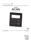
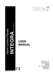
Figure 1. Hooking up the module to telephone line.
2. LIMITATIONS OF USE
As the mobile phones are designed for the maximum efficiency of speech conveyance,
the data compression feature which is used in them brings about distortions in
the transmitted audio signals, which may make difficult or even impossible sending modem
signals through a simulated telephone line (downloading, monitoring).
3. DESCRIPTION OF THE MODULE
MODULE TERMINALS:
+12V
– power supply input (12 V DC ±15%)
GND
– ground (0 V)
FLT
– alarm output, GSM telephone failure or insufficient range (OC; 50 mA)
R-1, T-1 – extension telephone line (connection to the alarm control panel or to
a telephone set)
IN1–IN4 – inputs
The FLT output is a generalized fault indicator. It gets active if connection with the base
station is not confirmed by the module within 10 minutes. It may be caused by a telephone
trouble (phone damaged or no SIM card), antenna failure (antenna cable damage), or loss of
range due to other reasons. The fault alarm stops maximum 30 seconds after the alarm
causes ceased to exist.
In its active state, the FLT output is shorted to the ground. The FLT output may be connected
to the alarm control panel input, or it can directly control the relay operation (its maximum
current-carrying capacity is 50 mA).
4
User manual
GSM LT-2
IN1 IN2 GND IN3 IN4
EXTERNAL ANTENNA CONNECTOR
GSM telephone
SIM CARD SOCKET
SIM
RS 232 INTERFACE
+12V GND FLT R-1 T-1
STAT
SIG
TX
RX
RS-232
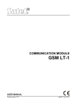
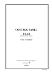
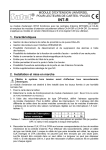
Figure 2. View of the GSM LT-2 module board.
LEDs:
The module indicates its status to the user by means of 4 LED indicators. The mode of
lighting of the STAT and SIG LEDs depends on the module status and provides
the information described below. The lighting cycle of these LEDs is 4 seconds, repeated
after a 1-second pause.
STAT – indicates the module status by a corresponding number of flashes with specified
duration. Shown symbolically below are single cycles of various LED lighting
modes with their meaning described. The shaded fields meaning the LED "on" and
the blank fields – the LED "off":
– (LED off) module power off
– no PIN code
– wrong PIN code
– PUK code required
– no communication with GSM telephone
– active connection
– normal operation of module
– module restart on switching power on
– PH-SIM PIN code required
– no SIM card
– SIM card damaged
– SIM card busy
– invalid SIM card
– PIN2 code required
– PUK2 code required
– other errors
GSM LT-2
SIG
SATEL
5
– indicates level of antenna signal received by GSM telephone (the LED goes out
when the module indicates trouble on the FLT output):
– no cellular network signal
– signal power 1
– signal power 2
– signal power 3
– signal power 4 (maximum signal)
TX, RX – data transmission indicators on RS-232 interface.
The cellular telephone is fitted with a special cable, terminated with connector for external
antenna (see: Fig. 2).
4. OPERATING THE GSM TELEPHONE
As any other cellular telephone, the industrial cellular telephone requires a SIM activation
card to operate. The user of the GSM LT-2 module has to obtain such a card on his own.
The SIM card should be inserted into a special recess provided on the right-hand side of the
printed circuit board. The PIN code, if necessary, is to be entered into the module memory by
means of a telephone connected to terminals R-1 and T-1 (programming function 16), or by
means of a computer and the DLOAD10 program.
Note: The change of PIN code stored in the SIM card, or entering the PUK code is possible
after putting the SIM card into an ordinary cellular telephone.
5. INSTALLATION
It should be borne in mind during installation that the GSM LT-2 module must not be located
in the vicinity of electrical installations, since this may involve a risk of malfunctioning.
Pay special attention to how the cable is laid between the module and the telephone
terminals of the alarm control panel.
Never turn on power supply of the module and GSM telephone without external
antenna connected.
The installation must be carried out in a strict compliance with the following activation
procedure:
1. Make a complete wiring.
2. Turn on the module power supply without SIM card inserted.
3. Using a DTMF telephone set or the DLOAD10 computer program, specify the module
working parameters (including the PIN code).
4. Turn off power supply.
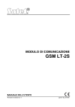
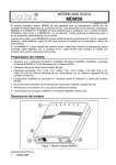
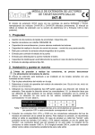
5. Insert SIM card into the socket (see: Fig. 3).
6. Turn on power supply.
A non-configured GSM LT-2 module will wait 10 minutes after power-up for entering the PIN
code of the SIM card. If this does not happen, the device will automatically deenergize the
telephone line and generate the trouble signal (i.e. it will short the FLT output to common
ground), thus making further programming from the telephone impossible (programming from
the computer by means of the DLOAD10 program will still be possible). If this is the case,
turn the module power off and on, so that the module can re-enter the programming mode.
The module power supply should have a sufficient current capacity. The recommended
power supply unit (e.g. APS-15; APS-30 manufactured by SATEL) should be equipped with
its own battery.
6
User manual
GSM LT-2
SIM card
1. slide the card
carrier up
2. turn the carrier aside and
slide the card into the
guides
3. press the carrier to the
plate and slide the
carrier down to fix it in
position
Figure 3. Entering the SIM card into its socket.
It is suggested that the power supply be located within 3 m from the module.
If the supply voltage is lower than 9.8 V, restart of the module will follow. Therefore, be
careful that the module supply voltage never drops during operation below 9.8 V at the
maximum current consumption.
6. OPERATION
OF THE MODULE WITH ALARM CONTROL PANEL AND STATIONARY
TELEPHONE
As shown in Figure 1, the module is to be directly connected to the control panel’s public
telephone line terminals.
It maintains impedance and voltage across the R-1 and T-1 terminals as necessary for
correct operation of the telephone set. The terminals can be automatically deenergized in
case of a loss of communication with the base station (which is accompanied by operation of
the FLT trouble indicator – see: programming function No. 17).
When the control panel goes "off-hook", or when a user lifts the handset of a telephone
connected to the terminals T-1 and R-1, the module will generate the continuous dialing tone
and receive the tone or pulse dialing signals (similarly as the telephone exchange).
The telephone number can include digits and special characters: #, *, +. The phone number
should be dialed just like from a cellular phone, as required by the operator of the network
into which the telephone is logged. It is recommended that the number begin with the "+"
character and country code prefix (48 for Poland). Sometimes you can dial just the mobile
phone number, or the area code and stationary telephone number.
Examples:
[*][0][4][8][5][0][1][1][2][3][4][5][6] – connection to mobile phone (with prefix "+48")
[5][0][1][1][2][3][4][5][6]
– connection to mobile phone (number without prefix)
[5][8] [1][2][3][4][5][6][7]
– connection to stationary telephone, (in this example, 58
is location area code)
If the first four digits of the dialed number correspond to the pre-programmed "pager station
number", the module goes to the procedure of receiving the alphanumeric message and
sending it as an SMS text message (see section Sending SMS messages). Checking of
the first four digits is always performed.
When connection is established by the cellular telephone, the module will transmit LF audio
signals between the extension line T-1, R-1 terminals and the cellular telephone. After the
handset is lifted by the subscriber the connection is established with, the module changes
GSM LT-2
SATEL
7
the direct voltage polarity across the extension line terminals T-1 and R-1. This function
makes it possible to keep individual tariffication of phone calls.
An option is provided for calling the phone number of the module SIM card. The incoming
calls are directed to the extension line terminals R-1 and T-1, which generates the ringing
tone, in much the same way as with operation of the cable telephone line. It is then possible
to answer the incoming calls by means of a stationary telephone set connected to that
telephone line.
The GSM LT-2 module makes it also possible to present the calling party number (CLIP) by
means of FSK or DTMF.
7. GSM LT-2 WITH MONITORING STATION
Figure 4.
The GSM LT-2 module permits site monitoring by means of SMS short text messages.
The SATEL's STAM-1 monitoring station only supports (from version 4.07) SMS monitoring
related to the input status of the GSM module located on the site (e.g. GSM-4S or
GSM LT-2). Changing the status of the device inputs will result in sending the event as an
SMS message with preprogrammed contents to the GSM module number on the monitoring
station side. The SMS message contents and the corresponding codes are to be defined in
the STAM program when editing the client.
The STAM-2 monitoring station (from version 1.2.0), besides monitoring the status of module
inputs, enables also full monitoring of events from the interfacing alarm control panel.
The panel is sending all events as SMS messages, the format of which (CID or 4/2) is to be
programmed by means of the DLOAD10 program (see: MONITORING). The contents of
SMS-messages and the corresponding codes are to be defined in the STAM-1/STAM-2
program when editing the client.
8
User manual
GSM LT-2
The example of module connection to station is shown in Fig. 4. Connect the GSM LT-2
module to the computer serial port (COM1 or COM2) with a cable made according to
Figure 6. Such a cable, designated with the DB9F/RJ-KPL symbol, is available in the
SATEL's offer.
8. INPUTS
The GSM LT-2 module is fitted with four inputs whose technical design is similar to that of the
control panel zones. Support of the inputs consists in monitoring any changes of their status.
Supervision of individual inputs can be bypassed by the module user. The inputs are
supported by the module irrespective of the telephone line support (R-1, T-1).
8.1 DESCRIPTION OF THE INPUTS
The detectors of both types, NC and NO, can be connected to the inputs of the module.
The type of detectors is to be entered in the service function 43.
The first parameter, the sensitivity of the input is programmed for each input (functions
45-48). The sensitivity of the input is defined as a minimum time which must elapse from
the moment of the status change at the input (open for NC input, closed for NO input),
in order to classify such change as violation of the input. This time delay can have the values
within the range from 20 ms to 1275 ms.
The time to restore the input is the next parameter to be programmed for each input
(function 44). Time to restore the input is defined as a time period that must elapse from the
end of input violation to the moment when the input can register a next violation (4 seconds
or 4 minutes).
Controlling the operation of inputs consists in bypassing and unbypassing their operation.
This control can be performed manually or remotely. The manual bypassing option can be
disabled (in service mode, using function 95). The remote control is effected by means of
a telephone which supports DTMF signaling (functions 82–91) as well as through SMS
messages (functions 71–80).
The input can be automatically bypassed after 1–15 violations, for a specified time, or
permanently (functions 49–60). The input is bypassed after the end of violation. Input can
also be bypassed after violating another input (designated as the bypassing input
- function 70). The bypassed status of the inputs as a result of violating the Bypassing input
will last as long as the given input is violated.
8.1.1 Bypassing by DTMF signals from R-1, T-1 terminals
To have the remote control by dual tone phone push-button (connected to R-1, T-1 terminals)
it is necessary to properly program the module by using the service functions, as follows:
• Enter the device service mode.
• Using function 95, determine the inputs to be bypassed manually.
• Program the (6-digit) control code to enable the inputs to by bypassed/unbypassed
locally – function 96.
• Exit the service mode by hanging up.
In order to bypass/unbypass an input do the following:
• Pick up the telephone receiver and enter the control code (if valid – the device will
generate four short and one long beeps).
• Bypass/unbypass input (according to the scheme described in function 96). Acceptance of
the command will be acknowledged by three short beeps.
Replace the receiver to make the device return to its normal operating mode.
GSM LT-2
SATEL
9
8.1.2 Remote bypassing by DTMF signals from touch – tone telephone keypad
To have the remote control it is necessary to program the module (from the R-1, T-1
terminals, or a computer with DLOAD10 program installed). To program the module do as
follows:
• Lift the telephone receiver and enter the service mode.
• Set the required duration of "Calling time" – function 93 (remember that remote control
will be prevented by the module if the time value is "0" !).
• Program the (four-digit) control codes for bypassing the inputs (functions 82–86).
The codes must not be repeated.
• Exit the service mode by hanging up.
For remote bypassing/unbypassing the inputs follow the sequence:
• Dial the GSM telephone number from any telephone having DTMF features (number of the
SIM card).
• Wait until "Time of ringing" is completed after which the module will answer a call and
generate three short sounds (beeps) acknowledging that the module is ready to have the
DTMF controlling enabled.
Note: When receiving a call, the module applies ringing tone to extension line for the
duration equal to "time of ringing". Answering a call from this extension line makes it
impossible to bypassing/unbypassing the inputs.
• Enter from dual tone phone keypad the required control passwords (utilizing DTMF tone
signals). After recognizing the password by the module, the respective action will be taken,
depending on the password loaded. For example, recognizing the password loaded in the
module by the function 82 – "Bypassing IN4" will bypass the supervision of input 4.
• The module acoustically acknowledges the execution of the function by audible indication
as follows:
à after bypassing/unbypassing the input, the module automatically checks the status of
the inputs and generates four sounds corresponding to the status of consecutive
inputs (1–4):
– short beep – input unbypassed,
– long beep – input bypassed,
(for instance: the sequence of signals – short, long, short, long indicate that inputs
1 and 3 are unbypassed, and inputs 2 and 4 are bypassed),
à two long beeps – the password is unknown to the module.
• Enter the next control password or hang up.
Note: If you have made a mistake when entering the code, press the 9 or # key and re-enter
the code from the beginning. If you enter a code unknown to the module three times,
the connection will be lost and the module will "hang up".
8.1.3 Remote bypassing – by SMS messages
To have the remote control of the GSM LT-2 by SMS, it is necessary to program the module
(from the R-1, T-1 terminals, or from a computer with the DLOAD10 program installed).
However, it should be remembered that using the DTMF signaling you can only program the
SMS messages composed of digits (0–9). The DLOAD10 program allows the user to enter
SMS messages of any content.
To program the module from R-1, T-1 terminals, do as follows:
• Lift the telephone receiver and enter the service mode.
• Program the content (6 alphanumeric characters) of control SMS messages (bypassing:
functions 71–75, unbypassing: functions 76–80). The content of the next SMS messages
10
User manual
GSM LT-2
must not repeat! (function 81 makes it possible to program the content of SMS message
informing about the status of inputs. Having received this message, the GSM LT-2 module
will send an SMS with input status information to the selected number).
• Exit the service mode by hanging up.
In order to remotely bypass/unbypass an input by using the SMS message, do as follows:
• using any mobile phone (or a stationary one, if equipped with the SMS function), send – to
the telephone number GSM – a text message containing the suitable control code
(a 6-character string, without any spaces or characters not belonging to the code inside).
Recognizing the code by the module in the message body will initiate the action,
depending on which code has been sent.
It is possible to send to the module an SMS message containing the code alone, as well as
a message longer than the code itself (it can be part of a longer word – among the 32 first
characters). Thus a verbal description of the current operation can be placed into memory of
the telephone from which the control will be executed (SMS sent). This will relieve the user
from the necessity to memorize the codes or the functions realized by them.
Only one control code can be sent in one message. If there are more codes, only the first one
will be executed by the module. Sending an SMS message which contains no code
(or contains a wrongly entered code) will cause no response from the device. The control
function is executed as soon as the message is received and the control code recognized.
Once the function has been executed, the received message will be deleted and the
telephone will be ready to receive a next control SMS message.
9. MESSAGING
This function is related to the attendance of module’s inputs, and is activated by violation or
restoration to normal status (termination of violation) of the input, which is not bypassed.
The messages can be sent maximally to four telephone numbers. The messaging can have
a form of SMS message or CLIP.
Another form of messaging is the "test transmission". In order to inform the user of its
operability, the module will send an SMS with suitable contents, or call selected telephone
numbers within the programmed time period. Information on the status of inputs, and
telephone line availability can be attached to the SMS message (function 94).
The telephone numbers to be notified and the test transmission period can be remotely
changed by sending SMS messages to the module. Such messages must contain the proper
password and the programmable parameter (functions 27–31). The module can inform the
user that a change has been made, by sending a return SMS to the telephone number
programmed with function 26. The SMS which is then sent contains information on the
current settings (transmission period and 4 telephone numbers to be notified, also for test
transmission purpose). For the module to return the SMS, the SMS centre number must be
programmed (function 02).
The first test transmission is carried out approx. 30 seconds after completion of the module
programming; the second one: after the programmed test transmission period, or randomly
(after a period not exceeding 20 hrs, unless duration of the programmed transmission period
is shorter). Subsequent transmissions are made in accordance with the programmed
parameter. Use function 19 or 25 for programming the duration of intervals between the test
transmissions.
When programming the test transmission data, set also the "test transmission priority" option
(function 20), as required.
Checking the current module status is also possible (function 99). It will suffice to dial the
GSM telephone number and hang up after a few call signals. A moment later the module will
generate an additional test transmission (independent of those already programmed), i.e. it
GSM LT-2
SATEL
11
will send to the calling number an SMS message (with or without the input status – see
function 94) or a CLIP signal (one-time, not requiring acknowledgement).
9.1 SMS MESSAGES
The SMS messages to be transmitted can have standard contents or can be modified by the
user (using DLOAD10 program only). The length of the message stored in the module’s
memory is limited to 32 characters.
The standard content of the SMS messages sent is as follows:
Event
Input 1 violation
Input 1 end of violation
Input 2 violation
Input 2 end of violation
Input 3 violation
Input 3 end of violation
Input 4 violation
Input 4 end of violation
Test transmission
SMS message
Input IN1 violation
Input IN1 restore
Input IN2 violation
Input IN2 restore
Input IN3 violation
Input IN3 restore
Input IN4 violation
Input IN4 restore
Test message
9.2 "CLIP"
Notification messaging is also possible owing to the CLIP service which consists in displaying
the telephone number of the calling subscriber. This type of messaging consists in dialing
a programmed telephone number and then breaking the connection after 50 seconds or the
time specified by the operator has elapsed. The message recipient can read information on
the number of the telephone from which the connection was initiated (cellular phone, ISDN,
etc.). If the number is busy, the module will repeat the call. The module will consider the
messaging completed, if it does not receive the busy signal within approx. 10 seconds from
dialing the number. The cellular phone user has an option to early "reject" the connection, but
if he carries out this action too early, the module will repeat the call. Answering the call, either
by the user or automatically by the "voice mail", is recognized by the module as completion of
messaging.
9.2.1 "CLIP" with acknowledgement
The transmission acknowledgement of the CLIP service consists in the telephone user
rejecting or receiving the connection set up by the GSM LT-2 module. The acknowledgement
can only take place within 10 to 20 seconds of the connection set-up. In addition, the number
of attempts (1–15) to make the transmission (functions 32 to 35) can be programmed
individually for each telephone number. The module will call in turn each of the programmed
numbers. Having detected the acknowledgement of CLIP transmission, the module will finish
dialing the given telephone number.
For each of the 4 telephone numbers programmed to be CLIP notified (functions 21–24), you
can select a separate option of sending SMS if there is no acknowledgement of receiving the
CLIP information (functions 36–39). If the module fails to detect such an acknowledgement
after making a preset number of attempts, then it will send an SMS to the given telephone
number, provided that the messaging mode with acknowledgement and SMS send is
selected. The SMS content will correspond to the existing situation.
9.2.2 "CLIP" without acknowledgement
In the CLIP service "without acknowledgement" transmission mode, the module will dial the
given telephone number once (provided the number is not busy), irrespective of the
programmed number of test transmission attempts.
12
User manual
GSM LT-2
Notes:
• If the cellular phone of the message addressee is OFF or outside the network range, and
the voice mail service is inactive, then an automatic message on the existing situation is
generated in the receiver and no busy signal is sent back. In such a case, the messaging
is considered by the module as completed, while the user loses information on completion
thereof.
• If the voice mail service is active, the user, after getting access to the network, may be
notified, depending on the operator (e.g. by means of an SMS) of the telephone
connection with the module number, without leaving any voice message.
To enable the messaging, it is necessary – after switching ON the GSM telephone and
connecting the sensors to the inputs – to program the module, as follows:
• Enter service mode.
• Program at least one telephone number to which the message is to be transmitted
(function 21–24).
• Program the required parameters for the inputs (type, sensitivity, time to restore,
automatic bypassing).
• If the SMS messaging is selected, program SMS Centre Number (function 02) and the
SMS message texts (only in DLOAD10).
10. TRANSMITTING SMS MESSAGES
If the alarm control panel has the function for messaging to pager system, it can be used for
sending SMS messages.
To enable the SMS messages to be sent, pre-program telephone number of pager station at
the alarm control panel and load appropriate text to be sent into the control panel memory.
The telephone number, as programmed in the control panel, must consist of:
1. The "pager station number" preprogrammed in the GSM LT-2 module (function 6).
2. The cellular phone number to which the SMS message is to be sent. The required country
code can be put before the main cellular phone number or it can be programmed by
a function 114.
Note: Parts of the number may not be separated from each other by any time interval
(pause); the digits must be sent by the control panel as one sequence in DTMF or
pulse mode. In case the module has any trouble with receiving the "pager" station
number in the tone mode, it is necessary to set the pulse dialing mode in the control
panel.
10.1 DESCRIPTION OF THE PROCEDURE FOR CONVERTING “PAGER” MESSAGE INTO SMS
MESSAGE
When the alarm control panel is "off hook" and after dialing the number – the module checks
the first four digits of that number. If these digits agree with the programmed "pager tel. no."
in the module, the module receives next digits up to the pause (telephone number to which
SMS message will be sent); then the module sends hand shake signal (similar as “pager”
station) and receives the message sent by the control panel. Next, this message is
transmitted via the GSM cellular telephone as SMS text message.
Notes:
• The pager station number has the form of 4 optional digits for module firmware version
2.11 and earlier. For module firmware version 2.12 and later, the pager number is
a sequence of 1 to 4 optional digits.
GSM LT-2
SATEL
13
• Pager number must be unique and can not be the same as any prefix, outgoing numbers
or the beginning of other telephone numbers.
The SMS sending systems may require adding a prefix with the country code (48 for
Poland). The prefix (without "+") is programmed with the service function 114. If the cellular
phone number is given by the control panel together with the prefix, then the function 114
should not be programmed.
To enable the transmission of SMS messages, the “SMS center No.", must be loaded into
the module, depending on the GSM network where the telephone is activated. It must be
preceded by the "+" character and the country code suitable for the operated network.
The parameters of the pager system signal should be programmed at the alarm control
panel (or telephone set DT-1) as follows:
control panel
DT-1
1
C
C
1
2
2
2
2
0
A
A
0
0
E
E
0
7
0
0
7
8
A
A
8
10.2 SENDING SMS MESSAGES FROM A STATIONARY TELEPHONE SET
The GSM LT-2 module user has an option to send SMS messages form a stationary
telephone set which generates DTMF signals and is connected to the terminals R-1 and T-1.
In order to send an SMS you should:
1. Lift the handset of the telephone.
2. Dial in one sequence the "PAGER station number"
and the phone number to which the SMS is to be
sent. The number should be entered rather
quickly, without any time intervals between
consecutive digits (indicate the country code
depending on how function 114 is programmed).
3. The properly received number is acknowledged in
the handset by two beeps generated by the
module. Lack of acknowledgement or a busy
signal means a dialing error and then the
procedure must be started anew (to facilitate it,
you can use the REDIAL option).
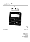
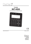
Figure 5. Assignment of alpha4. Enter the text of message following the
numeric
characters to telephone
instructions below (the time of module waiting for
keypad.
subsequent characters is not limited):
The module will accept characters in the numeric mode. Pressing each key of the
telephone adds a corresponding digit to the message.
By pressing the [*] key twice you will enter the text mode. In the text mode, each numeric
key (from 1 to 9) has three letters assigned to it (see Fig. 5). Pressing a key means
selection of the middle letter. By pressing in turn the key and [*] you will select the
left-hand letter on the given key. The right-hand letter is accessible by pressing the given
key and [#]. In order to reach the space, press the [0] key. To reach the dash, press [0][*],
the point – press [1]. In order to change between the text mode and the numeric mode,
press the keys [0] and [#]. Pressing the [#] key when the module is in the numeric mode
results in ending the programming and sending the message.
The GSM LT-2 can store in its memory 62 alphanumeric characters to be sent as an SMS
message. At an attempt to enter a longer message, the excessive portion of the text will be
omitted. There is no possibility to check the content of entered message. If you hang up the
handset when entering the text, the function will be interrupted without sending any SMS.
14
User manual
GSM LT-2
11. MONITORING
The GSM LT-2 module enables operation with two independent monitoring stations (using
GPRS transmission, SMS messages or audio signals). Reporting to the monitoring station
can include:
• GSM LT-2 module status,
• events from the control panel.
The telephone set (connected locally to terminals R-1, T-1) only enables programming
selected transmission parameters. The full programming requires that a computer with
DLOAD10 program be used (see: GPRS/Monitoring).
Note: Enabling the GPRS reporting option will disable the option of sending pager/SMS
messages.
11.1 MONITORING GSM LT-2 MODULE STATUS
Monitoring the module status is possible both when the module is working independently of
or in conjunction with the control panel. The connection is realized by means of the GSM
network (using GPRS).
The module is sending events pertaining to the status of inputs IN1–IN4 (violation/end of
violation) and test transmission to the station. The information can be sent in 4/2 or CID
(Contact ID) format. The format of events and the corresponding codes can only be
programmed from a computer with DLOAD10 program.
11.2 MONITORING CONTROL PANEL EVENTS
The GSM LT-2 module (from program version 2.11) enables full-scope reporting of the
control panel events to the monitoring station. It can be connected to the control panel
through the control panel telephone outputs (TIP, RING) or through the RS-232 port.
11.2.1 Connection through TIP, RING terminals
When connected to the control panel telephone output, the GSM LT-2 module will simulate
the telephone monitoring station, i.e. the control panel will dial the monitoring station
telephone number stored in its memory and, if it coincides with the station number
programmed in the module, the module will take over the connection and will send events to
the monitoring station through GPRS (function 110 will only enable monitoring through SMS).
Having sent an event to the station, the module will confirm delivery of the event with a preset
duration signal (function 100) and will wait for further events.
If there are any problems with the delivery of events through GPRS (e.g. a failure of the
monitoring station Ethernet card), the control panel will receive no confirmation that the event
message has been sent. In such a situation it will "hang up" and consider the monitoring
attempt unsuccessful. After a specified number of unsuccessful attempts (function 105), the
module can send an SMS message to the indicated telephone number (function 108),
informing about the problem, and make another attempt of monitoring the control panel
events through an alternative path:
• audio channel (function 104). The module will not simulate the monitoring station but will
establish connection to the monitoring station number, using the GSM telephone,
• as SMS (function 103). Each event will be sent as a separate SMS message to the mobile
telephone number on the monitoring station side.
11.2.2 Connection through RS-232 port
If the GSM LT-2 module is working with an INTEGRA series control panel,
the communication can also be effected through the RS-232 port. In such a case, the
GSM LT-2
SATEL
15
External modem and ISDN/GSM/ETHM modem options must be enabled on the control
panel side. When working in this configuration, the module only enables monitoring through
GPRS, according to the transmission parameters programmed in the control panel
(the module GPRS settings will be reprogrammed). It is possible to check the connection
between the INTEGRA control panel (in version 1.06 or later) and the module (function 98).
If there is no connection, the module will send information to the monitoring station.
Monitoring the control panel events can take priority over reporting the module status
(function 109).
12. MODULE PROGRAMMING
For the module to operate properly, corresponding parameters must be programmed.
The programming is possible by means of a stationary telephone capable of generating
DTMF signals, or by using a PC computer and the DLOAD10 program (version 1.00.29 or
later).
12.1 PROGRAMMING USING COMPUTER WITH DLOAD10 PROGRAM
The GSM LT-2 module is delivered together with the DLOAD10 program which enables the
module to be programmed from a computer.
The program is designed for IBM PC/AT compatible computers. It works in any computer
hardware configuration in the WINDOWS (9x/ME/2000/XP/Vista) environment. It is
recommended that the program be installed on the computer hard disk.
The GSM LT-2 module communicates with the computer via the RS-232 interface.
To connect the ports, use the cable made as shown on Fig. 6 (such a cable, designated with
the DB9F/RJ-KPL symbol, is available in the SATEL's offer).
TO MODULE
module DSR
module RTS
module RXD
module TXD
GND
TO COMPUTER
comp.DTR.
comp.CTS.
comp.TXD.
comp.RXD.
GND
(view of the RS-232 port on
the module board)
DB-9
5
4
3
2
8
(female connectors as
seen from soldering
points side)
Figure 6. Connection of computer to module serial port.
For installation of the program run the setup.exe program from a CD delivered with the
module.
Having installed the program, start it. Access to the program is protected with an access
code. After installation of the program, the access code is: 1234 and can be changed in any
string of 16 alphanumeric characters. As long as the code has its factory setting, pressing the
"ENTER" key (without entering any code) will start the program with the default access code
(1234).
16
User manual
GSM LT-2
In order to establish communication between the DLOAD10 program and the module, you
should follow the procedure below:
1. Open the window with module data by selecting FileÆNew deviceÆGSM4/LT module
in the program menu (see: Fig. 7).
Figure 7.
icon
2. Enter the options of module communication settings by clicking on the
(or through the Communication ÆConfiguration menu) and select the port through
which the computer connects with the module RS-232 port (see: Fig. 8).
Figure 8.
GSM LT-2
SATEL
17
3. Read out data from the module by clicking on the
icon.
4. Program the module. After starting the DLOAD10 program, the main window will open
(see: Fig. 9). The green bar in the upper part of the window shows the current status of
the module, antenna signal level and input status. Just below the green bar you can find 3
tabs: GSM LT-2, Inputs/Messaging and GPRS. They are described below.
5. Save new data in the module by clicking on the
icon.
6. If necessary, the programmed data can be saved as a file on the computer disk.
7. Disconnect the cable used for programming.
Note: Never carry out functional test of the module with cable connected to RS port.
12.1.1 "GSM LT-2" Tab
This tab allows the user to configure the basic working parameters of the module. The values
shown on Fig. 9 are just an example. By default, the data related to test transmission and
SMS control, as well as the PIN code, are not programmed. The parameters programmable
in the GSM LT-2 tab correspond to the control functions 1–42, 93, 94, 98, 99 and 111-114
and have been reviewed at the local control (DTMF) description in section Module
Programming.
Figure 9.
12.1.2 "Inputs/Tel. messaging" Tab
The options provided in this tab (see: Fig. 10) enable configuration of the module input
parameters (i.a. type, sensitivity, restore time), remote control (via SMS and DTMF) and
messaging (CLIP and/or SMS about input violation/restore, as well as test transmission
18
User manual
GSM LT-2
enable/disable). The parameters programmable in this tab correspond to the control functions
43–92, 95, 96 and have been reviewed at the local control (DTMF) description in sections:
Inputs and Messaging.
Figure 10.
12.1.3 "GPRS/Monitoring" tab
The GPRS monitoring function, supported by the GSM LT-2 module, is dedicated to
interaction with monitoring stations which receive transmissions sent through TCP/IP
(the STAM-2 monitoring station provided with the STAM-1 PE or STAM-1 RE card or any
other monitoring station provided with the SMET-256 converter).
In order to initialize the GPRS transmission, its parameters must be programmed (they are
not programmed by default). Figure 11 shows a view of the GPRS tab. The presented values
are just examples. Full configuration is only possible from a computer with DLOAD10
program (in version 1.00.031 or later).
The basic parameters, obtained from the operator of GSM network in which the GSM
telephone is working, include:
• APN – name of access point for Internet GPRS connection,
• User – user name for Internet GPRS connection,
• Password – code for Internet GPRS connection,
• DNS server – DNS server IP address to be used by the module. The DNS server IP
address is necessary if the data are transmitted using GPRS technology, while the IP
address of the monitoring station is entered in name form. If all the IP addresses are
entered in numerical form (4 decimal numbers separated by dots), the DNS server
address need not be programmed.
GSM LT-2
SATEL
19
Next, the parameters (obtained from the administrator of the given monitoring station)
which enable communication between the GSM LT-2 module and the monitoring station are
to be programmed:
• Station address – IP address of the monitoring station. It can be entered in the form of
a name or in the form of a number.
• Port – number of the TCP port through which communication with the monitoring station
will be effected. Values from 1 to 65535 can be entered. The port number must correspond
to that defined in the monitoring station.
• Station key – a sequence of 1 to 12 alphanumeric characters (digits, letters and special
characters), which define the key for coding the data to be sent to the monitoring station.
It must correspond to that defined in the monitoring station.
• System identifier – a sequence of 4 characters (digits or letters from A to F) to identify
the module. Using the digit 0 in the identifier is not recommended. Default value: 0000 (this
sequence is tantamount to "no identifier").
• GPRS key – a sequence of 1 to 5 alphanumeric characters which identify the
GSM/GPRS module. It must correspond to that defined in the monitoring station
("ETHM/GPRS key").
Figure 11.
20
User manual
GSM LT-2
If the status of GSM LT-2 module is to be monitored, indicate the following:
• monitoring station to which events will be sent (columns S1 and S2)
• format of events sent in the GPRS transmission (column Format). The device supports
two event formats:
– 4/2 – two digits indicating the event code (CODE column),
– CID (Contact ID) – requires entry of information describing the event (columns CODE
event code, R – violation/restore, Part. – partition, No. – input number). For this
purpose, you can use the code generator (see Fig. 12), started by clicking on the
button:
Figure 12. View of the CID code generator.
The generator enables the CID event code to be quickly defined:
⎯ Group – event type,
⎯ Event – event code and description,
⎯ Partition – partition number to be sent,
⎯ Zone /Module/User – zone/module/user number to be sent.
Where events of the control panel connected to the module are to be monitored, you should
also to configure the following parameters:
• Telephone line reporting only as SMS – if this option is selected, the control panel
events will only be sent to the monitoring station as SMS messages (with no attempt of
sending them through GPRS),
• RS-232 reporting priority – if this option is selected, monitoring the events of the control
panel connected to the module through the RS-232 port will take priority over reporting the
GSM LT-2 module status
• Monitoring Station 1 & 2 telephone numbers – the telephone numbers defined in the
control panel for the given monitoring station. The module will simulate receiving the event
codes by these stations. If the numbers are not programmed or are inconsistent with those
programmed in the control panel, the module will be unable to receive the event codes
sent by the control panel. If sending the event codes with the use of GPRS technology
fails, the module will be able to send them to the programmed telephone numbers, using
the voice channel.
• Kissoff time – duration of the signal generated by the module to confirm receiving the
event from the control panel. The entered value must be suitable for the control panel
settings (selected monitoring format). Values from the 100 to 2550 ms range can be
programmed (by default: 850 ms). Factory setting: 850 ms.
• Number of control panel reporting retries before sending other way - the parameter
defines the number of failed attempts to send events through GPRS, after which the
control panel will make an attempt to send them through an alternative path (2-255, by
default: 3):
GSM LT-2
SATEL
21
⎯ audio channel – if the option Use GSM audio channel if GPRS trouble is selected;
the module will not simulate but it will establish connection (using the GSM telephone)
to the monitoring station number,
⎯ as SMS message – when the option Send as SMS if GPRS trouble. Each event will
be sent as a separate SMS message to the mobile telephone number on the
monitoring station side (Station 1 and Station 2),
• SMS format for Station 1 and Station 2 – the SMS message format for SMS monitoring.
It must be defined as required by the monitoring station. The SMS message format which
is programmed by default corresponds to the default settings of the STAM-2 monitoring
station (program version 1.2.0 or newer). For the 4/2 formats, only the identifier and event
code will be sent. Question marks will be sent instead of any other information.
• GPRS reporting trouble messaging – it is possible to send an SMS message with
preprogrammed contents to the indicated telephone number in case of GPRS reporting
trouble.
12.2 PROGRAMMING BY MEANS OF A TELEPHONE SET
It is possible to program the basic parameters, which are necessary for operation of the
module (without GPRS monitoring), as well as to check the module status, by using
a stationary telephone connected to the R-1, T-1 terminals.
In order to change the settings or check the status you should first enter the GSM LT-2
module programming mode. This operation requires entering a six-digit access code.
(by default, this code is [1][2][3][4][5][6]). In case you have forgotten the code after the
change, you can only view it or restore it by means of the computer and the DLOAD10
program.
12.2.1 Calling the GSM LT-2 module programming mode
• Lift the handset of the telephone.
• Select the following key sequence on the keypad:
[*][*][*][*][*][*][?][?][?][?][?][?][*][*][*][*][*][*][#] – (6 asterisks; access code; 6 asterisks; #)
• The module will confirm entering the programming mode with four short and one long
beeps hearable in the telephone handset and will wait for individual functions to be called
to program the settings. It will remain in the programming mode until the handset is
hanged up.
Note: The module accepts the call of programming mode irrespective of the signals it
generates in the handset (e.g. the line busy signal can be heard, if there is no SIM
card inserted).
In the process of programming, the module communicates with the user by means of beeps
that can be heard in the telephone handset. These beeps (tones) are symbolically denoted in
the function description by means of capital letters:
S – short beep
L – long beep
12.2.2 Programming the module settings
Programming the module is effected by entering the suitable control functions. The general
form of such a function looks as follows:
[x][x][*][*][?][?][?][?…][#]
In order to call the programming function, select the function number (two digits), press the
[*] asterisk key twice, enter the parameter suitable for the given function and press the [#]
key. The parameter length (number of characters "?") depends on the type of function.
22
User manual
GSM LT-2
Where the number of digits is not precisely defined (e.g. a telephone number), such
a parameter is described with the following symbol: [?...].
The numbers of telephones/PAGER stations may contain special characters: #, *, +. In order
to program such a character from the telephone keypad, call the programming function and
press successively the two keys:
[*][1] = #
[*][*] = *
[*][0] = +
Entering a correct command is signaled in the handset by three short beeps (SSS), while
commands which are incomprehensible or have an incorrect number of characters are
signaled by two long beeps (LL).
The function completed, the module returns to the programming mode. If you hang up,
the module will quit the programming mode and return to the normal operating mode.
12.2.3 Function list
[0][1][*][*][?][?][?][?][#] – SIM card PIN code (4 digits). The code saved in module memory
does not change the code stored on the SIM card. The [0][1][*][*][#] sequence deletes the
PIN code from module memory.
[0][2][*][*][?...][#] – SMS center number – the telephone number necessary for sending text
messages. The number of its digits must be within the range of 1...16. The entered
number depends on the GSM network, where the telephone is activated. It must be
preceded by the country code suitable for the operated network.
The [0][2][*][*][#] sequence deletes the previously saved SMS center number.
[0][3][*][*][?][?][?][?][?][?][#] – SMS password (6 characters) required for a remote
change of the modem format. Sending to the module of an SMS containing the
[?][?][?][?][?][?]=NN sequence will change the modem operating format available in the
GSM telephone. The two NN digits define the format as described in the function 08. Using
DTMF signals it is possible to program a password comprised of digits only (0...9), while
using the DLOAD10 program you can program a password comprised of both letters and
digits. The [0][3][*][*][#] sequence deletes the previously programmed password.
[0][4][*][*][?][?][?][?][?][?][#] – SMS password (6 characters) starting connection with
DLOAD program. The function applies to interaction between the module and the
INTEGRA/CA-64 alarm control panel. Sending to the module of an SMS containing the
programmed password makes the control panel call back to the number saved in its
memory as the "DLOADX telephone"/"DLOAD64 telephone" in order to start the
downloading function. If the control panel is to call back to another number, the number
should be put into the SMS content as follows: [?][?][?][?][?][?]=dddd. (password, equality
sign, telephone number, dot). If the module receives an SMS message initiating
connection with the INTEGRA control panel and the access from DLOADX program is
blocked, the module will send a SMS message stating that "Remote access from DloadX
program is not granted" to the number preprogrammed with function 26.
Using DTMF signals it is possible to program a password comprised of digits only (0...9),
while using the DLOAD10 program you can program a password comprised of both letters
and digits. The [0][4][*][*][#] sequence deletes the previously programmed password.
[0][5][*][*][?][?][?][?][?][?][#] – SMS password (6 characters) starting connection with
GUARD program. The function applies to interaction between the module and the
INTEGRA/CA-64 alarm control panel. Sending to the module of an SMS containing the
programmed password makes the control panel call back to the number saved in its
memory as the "GuardX telephone"/"Guard64 telephone" in order to start the remote
communication with the GUARDX/GUARD64 program. If the control panel is to call back
to another number, the number should be put into the SMS content as follows:
GSM LT-2
SATEL
23
[?][?][?][?][?][?]=gggg. (password, equality sign, telephone number, dot). Using DTMF
signals it is possible to program a password comprised of digits only (0...9), while using the
DLOAD10 program you can program a password comprised of both letters and digits.
The [0][5][*][*][#] sequence deletes the previously programmed password.
[0][6][*][*][?][?][?][?][#] – PAGER station number is 4 digits or a sequence of 1 to 4 digits
(depending on the module firmware version). If the module detects these digits at the
beginning of the dialed number, it will handle the further part of the number as the number
of cellular phone to which it is necessary to send the SMS. The SMS contents should be
transmitted by the alarm control panel (or dialer) in the "pager" system form.
The [0][6][*][*][#] sequence will delete the number.
[0][7][*][*][?][?][?][?][#] – CA-64 station number (4 digits). This function is not used.
The [0][7][*][*][#] sequence will delete the number.
[0][8][*][*][?][?][#] – modem standard format (2 digits) – the format in which the module
will communicate with the modem of service/user computer. The format code is to be
entered as two digits according to the table below:
format code
00
01
02
03
04
05
06
07
12
14
65
66
68
70
71
75
modem format
auto
300 V.21
1200 V.22
1200/75 V.23
2400 V.22bis
2400 V.26ter
4800 V.32
9600 V.32
9600 V.34
14400 V.34
300 V.110
1200 V.110/X.31
2400 V.110/X.31
4800 V.110/X.31
9600 V.110/X.31
14400 V.110/X.31
[0]9][*][*][?][#] – RS-232 port speed. Parameter defining the rate of data transfer between
the module and the control panel/computer:
0 – 4800 bps,
1 – 9600 bps,
2 – 19200 bps.
[1][0][*][*][?][#] – SMS center international number. The option indicates whether the
programmed SMS center number is a full international number:
0 – no (for local networks),
1 – yes (recommended).
[1][1][*][*][?][#] – Fax/Modem. Option indicating whether the user permits a modem
transmission to be carried out by the module:
0 – transmission disabled,
24
User manual
GSM LT-2
1 – transmission enabled.
[1][2][*][*][?][?][?][?][?][?][#] – access code (6 digits) for programming the module by
means of a telephone set (connected to the R-1, T-1 terminals). The [1][2][*][*][#]
sequence will delete the code i.e. deny the access to programming. When you delete the
code and quit the programming mode, you will only be able to change the settings and
restore the code by using a PC computer and the DLOAD10 program.
[1][3][*][*][1][2][3][4][#] – restore default settings (the default access code for module
programming is 123456).
[1][4][*][*][#] – antenna signal strength. The module, by means of handset beeps, informs
the user about the level of received antenna signal. The signaling is same as that of the
SIG LED:
two long (LL) – antenna signal strength = 0
one short (S) – antenna signal strength = 1
two short (SS) – antenna signal strength = 2
three short (SSS) – antenna signal strength = 3
four short (SSSS) – antenna signal strength = 4 (maximum).
[1][5][*][*][#] – telephone status. The module informs the user about its status.
The signaling is same as that of the STAT LED:
four short (SSSS) – no SIM PIN code,
three short (SSS) – wrong SIM PIN code,
short and long (SL) – SIM PUK code required,
two short (SS) – no communication with the GSM telephone,
one short (S) – module operation OK,
two long (LL) – module restart after power-up,
two short and one long (SSL) – PH-SIM PIN code required,
eight short (SSSSSSSS) – no SIM card,
three long (LLL) – SIM card damaged,
four beeps of diminishing length (LlSs) –SIM card busy,
long, short, long, short (LSLS) – incorrect SIM card,
three short and one long (SSSL) – SIM PIN2 code required,
four short and one long (SSSSL) – SIM PUK2 code required,
one long, three short and one long (LSSSL) – other error.
[1][6][*][*][?][?][?][?][?][?][?][?][#] – PUK code (8 digits). The function is only executable
when the module status (indicator LED or beeps) indicates that the PUK code must be
entered. The code is required for unblocking the SIM card (the blocking occurs when the
PIN code entered into the module memory (function 01) is different from the SIM card PIN
code).
Important! After entering the PUK code and unblocking the SIM card, its PIN code will be
changed to that currently set in the module memory. To avoid this situation, the
user must enter into the module memory a PIN code which is identical to that
saved in the SIM card. The DLOAD program allows you to preview the PIN code
currently programmed in the module, so that the card blocking can be avoided.
Entering the PUK code will be confirmed by three short beeps (SSS). This
acknowledgment will occur after a few second delay, because of data processing in the
GSM telephone. If the PIN code is not entered into the module, the function will not be
executed and the device will generate two long beeps (LL).
GSM LT-2
SATEL
25
[1][7][*][*][?][#] – deenergizing the telephone line together with signaling fault at the FLT
output:
0 – do not switch off voltage on telephone line terminals,
1 – switch off voltage on telephone line if FLT is active
(programming mode – if it was turned on before activating FLT, it will be operative, but
only until hang-up).
[1][8][*][*][?][#] – generating the routing signal (sound signal for setting up connection):
0 – signal OFF,
1 – signal ON.
[1][9][*][*][?][#] – test transmission. The function enters the period of CLIP test
transmission in a simplified way. The following values can be entered:
0 – no test transmission,
1 – test transmission period
2 h 58 min,
2 – test transmission period
5 h 57 min,
3 – test transmission period
11 h 56 min,
4 – test transmission period
23 h 55 min,
5 – test transmission period
2 d 23 h 53 min,
6 – test transmission period
6 d 23 h 30 min.
If the function is called as [1][9][*][*][?][?][#], the second "?" character will define whether
the second test transmission is to be random, or not:
0 – no,
1 – yes.
When the default settings are restored (function 13), the random transmission will be
disabled.
[2][0][*][*][?][#] – test transmission priority. This option determines whether the test
transmission will override the call being just carried out by the module. If yes, the current
connection will be terminated whenever there is a need for the test transmission. If no,
the test transmission will be carried out on completion of the call by the control panel/user:
0 – no,
1 – yes.
[2][1][*][*][?...][#] – telephone number 1 for the messaging. The number of digits must be
within the range of 1...16. The number should be programmed with "+" at the beginning,
followed by the country code. The [2][1][*][*][#] sequence will erase the previously saved
telephone number.
[2][2][*][*][?...][#] – telephone number 2 for the messaging. The same settings as for
telephone 1.
[2][3][*][*][?...][#] – telephone number 3 for the messaging. The same settings as for
telephone 1 (function 21).
[2][4][*][*][?...][#] – telephone number 4 for the messaging. The same settings as for
telephone 1 (function 21).
[2][5][*][*][?][?][?][?][?][?][#] – test transmission period (6 digits: ddhhmm). As distinct
from function 19, this function enables any transmission period to be entered.
The programmed digits have the following meaning: dd – number of days (max. 31),
hh – number of hours (max. 23),
mm – number of minutes (max. 59).
If the function is called as [2][5][*][*][?][?][?][?][?][?][?][#], the seventh "?" character will
define whether the second test transmission is to be random, or not:
26
User manual
GSM LT-2
0 – no,
1 – yes.
When the default settings are restored (function 13), the random transmission will be
disabled. Programming zeros only will reset the test transmission.
[2][6][*][*][?...][#] – telephone number to confirm SMS control. The number to which the
module will send an SMS to inform about the current settings, provided that the user has
changed the settings by means of an SMS. The telephone number must be preceded by
the "+" character and country code, corresponding to the currently used GSM network.
The [2][6][*][*][#] sequence will erase the previously saved telephone number.
[2][7][*][*][?][?][?][?][?][?][#] – SMS password (6 characters) makes it possible to remotely
change the test transmission period. Sending to the module an SMS with the
[?][?][?][?][?][?]=P sequence, where P is a parameter corresponding to the description
contained in function 19, will save the new parameter, programmed with function 19, in the
module memory. Using the DTMF signals, you can program passwords composed from
digits only (0...9), whereas the DLOAD10 program makes it possible to program
passwords composed from letters and digits. The [2][7][*][*][#] sequence will erase the
previously programmed password.
[2][8][*][*][?][?][?][?][?][?][#] – SMS password (6 characters) makes it possible to remotely
change the telephone number 1 for messaging. Sending to the module an SMS with the
[?][?][?][?][?][?]=nnnn. sequence (password, equality sign, telephone number, dot), where
nnnn is the new telephone number 1 for messaging, will change the parameter
programmed with function 21. The new telephone number must be identical in form to that
programmed with the appropriate function. Using the DTMF signals, you can program
passwords composed from digits only (0...9), whereas the DLOAD10 program makes it
possible to program passwords composed from letters and digits. The [2][8][*][*][#]
sequence will erase the previously programmed password.
[2][9][*][*][?][?][?][?][?][?][#] – SMS password (6 characters) makes it possible to remotely
change the telephone number 2 for messaging. The same settings as for telephone 1.
[3][0][*][*][?][?][?][?][?][?][#] – SMS password (6 characters) makes it possible to remotely
change the telephone number 3 for messaging. The same settings as for telephone 1.
[3][1][*][*][?][?][?][?][?][?][#] – SMS password (6 characters) makes it possible to remotely
change the telephone number 4 for messaging. The same settings as for telephone 1.
[3][2][*][*][?...][#] – number of CLIP notification attempts to telephone no. 1. You can
program from 1 to 15 attempts.
[3][3][*][*][?...][#] – number of attempts of CLIP type messaging to telephone no. 2. You
can program from 1 to 15 attempts.
[3][4][*][*][?...][#] – number of attempts of CLIP type messaging to telephone no. 3. You
can program from 1 to 15 attempts.
[3][5][*][*][?...][#] – number of attempts of CLIP type messaging to telephone no. 4. You
can program from 1 to 15 attempts.
[3][6][*][*][?][#] – kind of CLIP messaging to telephone no. 1:
0 – CLIP without acknowledgement,
1 – CLIP with acknowledgement,
2 – CLIP with acknowledgement and SMS send, when there is no acknowledgement.
[3][7][*][*][?][#] – kind of CLIP messaging to telephone no. 2. The same settings as for
telephone 1.
[3][8][*][*][?][#] – kind of CLIP messaging to telephone no. 3. The same settings as for
telephone 1.
GSM LT-2
SATEL
27
[3][9][*][*][?][#] – kind of CLIP messaging to telephone no. 4. The same settings as for
telephone 1.
[4][0][*][*][#] – contents of SMS sent in case of no acknowledgement (default content of
these SMS messages can only be changed by means of the DLOAD10 program).
[4][1][*][*][?...][#] – substitutes the "+" character of incoming number with a chosen
sequence (from 0 to 4 digits) – the function refers to the CLIP type information and work in
conjunction with STAM-1, STAM-2 monitoring station.
[4][2][*][*][?][#] – identification of the calling number (CLIP):
0 – disabled,
1 – FSK,
2 – DTMF.
[4][3][*][*][?][?][?][?][#] – input types IN1–IN4:
0 – NC,
1 – NO.
[4][4][*][*][?][?][?][?][#] – restore times, inputs IN1–IN4:
0 – short (4 seconds),
1 – long (4 minutes).
[4][5][*][*][?...][#] – sensitivity of input IN1. The following values can be programmed
(in milliseconds): 20, 40, 60, 80, 100, 130, 160, 200, 250, 300, 400, 500, 600, 800, 1000,
1275.
[4][6][*][*][?...][#] – sensitivity of input IN2. The same value settings as for input IN1.
[4][7][*][*][?...][#] – sensitivity of input IN3. The same value settings as for input IN1.
[4][8][*][*][?...][#] – sensitivity of input IN4. The same value settings as for input IN1.
[4][9][*][*][?...][#] – number of violations after which the module will automatically
bypass input IN1 (from 0 to 15), 0 – no bypassing.
[5][0][*][*][?...][#] – number of violations after which the module will automatically
bypass input IN2 (from 0 to 15), 0 – no bypassing.
[5][1][*][*][?...][#] – number of violations after which the module will automatically
bypass input IN3 (from 0 to 15), 0 – no bypassing.
[5][2][*][*][?...][#] – number of violations after which the module will automatically
bypass input IN4 (from 0 to 15), 0 – no bypassing.
[5][3][*][*][??...][#] – time, after expiry of which the violation counter of input IN1 will be
reset. The first "?" character determines the time unit (0 – seconds, 1 – minutes); enter
a numerical value (from 0 to 127) in place of the other "?" characters; 0 – without counter
reset.
Note! The reset time of violation counter must be longer than the input restore time (see:
function 44). Otherwise, the input will not be bypassed, because the counter sums up
the input violations after the initial status is restored.
[5][4][*][*][??...][#] – time, after expiry of which the violation counter of input IN2 will be
reset. The same settings as for input IN1.
[5][5][*][*][??...][#] – time, after expiry of which the violation counter of input IN3 will be
reset. The same settings as for input IN1.
[5][6][*][*][??...][#] – time, after expiry of which the violation counter of input IN4 will be
reset. The same settings as for input IN1.
[5][7][*][*][??...][#] – bypassing time, input IN1. The first "?" character determines the time
unit (0 – seconds, 1 – minutes); enter a numerical value (from 0 to 127) in place of the
other "?" characters; 0 – permanently bypassed (until manually unbypassed).
28
User manual
GSM LT-2
[5][8][*][*][??...][#] – bypassing time, input IN2. The same settings as for input IN1.
[5][9][*][*][??...][#] – bypassing time, input IN3. The same settings as for input IN1.
[6][0][*][*][??...][#] – bypassing time, input IN4. The same settings as for input IN1.
[6][1][*][*][????][#] – telephone numbers to which the input IN1 violation will be notified.
The first "?" character refers to telephone 1, the second "?" character – to telephone 2, etc.
These characters can have the following value:
0 – no messaging,
1 – CLIP messaging,
2 – SMS messaging.
[6][2][*][*][????][#] – telephone numbers, to which the input IN2 violation will be
notified. The same settings as for input IN1.
[6][3][*][*][????][#] – telephone numbers, to which the input IN3 violation will be
notified. The same settings as for input IN1.
[6][4][*][*][????][#] – telephone numbers, to which the input IN4 violation will be
notified. The same settings as for input IN1.
[6][5][*][*][????][#] – telephone numbers, to which the input IN1 restore will be notified.
The first "?" character refers to telephone 1, the second "?" character – to telephone 2, etc.
These characters can have the following value:
0 – no messaging,
1 – CLIP messaging,
2 – SMS messaging.
[6][6][*][*][????][#] – telephone numbers, to which the input IN2 violation will be notified.
The same settings as for input IN1.
[6][7][*][*][????][#] – telephone numbers, to which the input IN3 violation will be notified.
The same settings as for input IN1.
[6][8][*][*][????][#] – telephone numbers, to which the input IN4 violation will be notified.
The same settings as for input IN1.
[6][9][*][*][????][#] – telephone numbers, which will be notified during test
transmission. The first "?" character refers to telephone 1, the second "?" character – to
telephone 2, etc. These characters can have the following value:
0 – no messaging to the given number,
1 – CLIP messaging,
2 – SMS messaging.
[7][0][*][*][?????][#] – function specifying the number of input whose violation will
bypass the specified module inputs. The first "?" character indicates the bypassing
input (0 – none, 1...4 – respectively IN1–IN4), subsequent 4 "?" characters define which of
the other inputs is to be bypassed (0 – no, 1 – yes).
[7][1][*][*][??????][#] – SMS code (6 alphanumeric characters) used for bypassing the
input IN1. Using the DTMF tone signaling makes it possible to program the SMS content
only composed of digits (0–9). The DLOAD10 program enables creating SMS messages
of any content. The sequence [7][1][*][*][#] will delete the SMS code.
[7][2][*][*][??????][#] – SMS code for bypassing the input IN2. The same settings as for
input IN1.
[7][3][*][*][??????][#] – SMS code for bypassing the input IN3. The same settings as for
input IN1.
[7][4][*][*][??????][#] – SMS code for bypassing the input IN4. The same settings as for
input IN1.
GSM LT-2
SATEL
29
[7][5][*][*][??????][#] – SMS code (6 alphanumeric characters) used for bypassing all
inputs. Using the DTMF tone signaling makes it possible to program the SMS content only
composed of digits (0–9). The DLOAD10 program enables creating SMS messages of any
content. The sequence [7][5][*][*][#] will delete the SMS code.
[7][6][*][*][??????][#] – SMS code (6 alphanumeric characters) used for unbypassing the
input IN1. Using the DTMF tone signaling makes it possible to program the SMS content
only composed of digits (0–9). The DLOAD10 program enables creating SMS messages
of any content. The sequence [7][6][*][*][#] will delete the SMS code.
[7][7][*][*][??????][#] – SMS code for unbypassing the input IN2. The same settings as
for input IN1.
[7][8][*][*][??????][#] – SMS code for unbypassing the input IN3. The same settings as
for input IN1.
[7][9][*][*][??????][#] – SMS code for unbypassing the input IN4. The same settings as
for input IN1.
[8][0][*][*][??????][#] – SMS code (6 alphanumeric characters) used for unbypassing all
inputs. Using the DTMF tone signaling makes it possible to program the SMS content only
composed of digits (0–9). The DLOAD10 program enables creating SMS messages of any
content. The sequence [7][5][*][*][#] will delete the SMS code.
[8][1][*][*][??????][#] – SMS code (6 alphanumeric characters) for checking the input
status. Using the DTMF tone signaling makes it possible to program the SMS content only
composed of digits (0–9). The DLOAD10 program enables creating SMS messages of any
content. The sequence [8][1][*][*][#] will delete the SMS code.
[8][2][*][*][????][#] – DTMF code (4 digits from the 0–9 range) for bypassing the input
IN1. The sequence [8][2][*][*][#] will delete the code.
[8][3][*][*][????][#] – DTMF code (4 digits from the 0–9 range) for bypassing the input
IN2. The same settings as for input IN1.
[8][4][*][*][????][#] – DTMF code (4 digits from the 0–9 range) for bypassing the input
IN3. The same settings as for input IN1.
[8][5][*][*][????][#] – DTMF code (4 digits from the 0–9 range) for bypassing the input
IN4. The same settings as for input IN1.
[8][6][*][*][????][#] – DTMF code (4 digits from the 0–9 range) for bypassing all inputs.
The sequence [8][6][*][*][#] will delete the code.
[8][7][*][*][????][#] – DTMF code (4 digits from the 0–9 range) for unbypassing the input
IN1. The sequence [8][7][*][*][#] will delete the code.
[8][8][*][*][????][#] – DTMF code (4 digits from the 0–9 range) for unbypassing the input
IN2. The same settings as for input IN1.
[8][9][*][*][????][#] – DTMF code (4 digits from the 0–9 range) for unbypassing the input
IN3. The same settings as for input IN1.
[9][0][*][*][????][#] – DTMF code (4 digits from the 0–9 range) for unbypassing the input
IN4. The same settings as for input IN1.
[9][1][*][*][????][#] – DTMF code (4 digits from the 0–9 range) for unbypassing all inputs.
The sequence [9][1][*][*][#] will delete the code.
[9][2][*][*][????][#] – DTMF code (4 digits from the 0–9 range) for checking the input
status. The sequence [9][2][*][*][#] will delete the code.
[9][3][*][*][?..][#] – the "calling time". The parameter defines the time (counted in seconds,
from the 1 to 99 range), after which the GSM telephone will:
− reject the connection (if no inputs/outputs control code has been programmed, or
nobody will answer the call from the extension line R-1, T-1),
30
User manual
GSM LT-2
− establish connection (if an inputs/outputs control code has been programmed) to enable
remote control.
During the "calling time" the module will transmit the bell signal to the terminals R-1, T-1
and connection can be established from the telephone connected to the extension line.
When the "0" value is entered, the device will neither reject, nor receive connections,
which will make the DTMF signal control impossible.
[9][4][*][*][?][#] – when this option is enabled, information on the current status of module
inputs will be included in the SMS for test transmission. The "?" character can have two
values:
0 – SMS test transmission without module input status,
1 – SMS test transmission with module input status.
[9][5][*][*][????][#] – function defining which inputs can be bypassed manually. The "?"
characters which correspond to the consecutive inputs (IN1–IN4) can have the following
value:
0 – input may not be bypassed,
1 – input may be bypassed.
[9][6][*][*][??????][#] – the number which enables manual control of the inputs
(through DTMF tone signaling) from a telephone set connected to the extension line (R-1,
T-1). Editing is similar as in function 06.
The control is available after dialing the number which has been programmed here, after
which you should enter control sequences, consisting of the "*" character and 2 digits: the
first digit defines the function, the other one – the input number ("0" meaning that the
selected function is used for all inputs). Execution of the entered control sequence will be
acknowledged by three short beeps (two long beeps if an error occurs). Press "*" to reset
the buffer (i.e. function selection). Functions:
1 – bypass input,
2 – unbypass input,
3 – check input status (in response, the device will generate the following beeps):
1 short beep – input unbypassed,
3 long beeps – input bypassed.
The sequence [9][6][*][*][#] will delete the number which enables control.
[9][7][*][*][?][#] – GPRS transmission support:
0 – no,
1 – yes.
Note! The telephone line terminals (R-1, T-1) make it only possible to program selected
parameters of the GPRS transmission. Full configuration can be effected by using the
computer with DLOAD10 program installed.
[9][8][*][*][?][#] – control of communication with the INTEGRA control panel:
0 – no,
1 – yes:
Note! This option is available for INTEGRA control panels in version 1.06 or later.
[9][9][*][*][?][#] – type of response to the user's CLIP in order to confirm availability of
the device:
0 – none,
1 – CLIP,
2 – SMS.
GSM LT-2
SATEL
31
[9][9][*][*][7][8][9][0][[#] – test mode of the module. Calling this function will make all the
indicator LEDs go out. Then they will light up for approx. 1 second in the following
sequence: STAT, SIG, TX, RX, and next the FLT output will be activated.
[1][0][0][*][*][?...][#] – acknowledgement duration (100–2550 ms). The default value is
850 ms.
[1][0][1][*][*][?...][#] – telephone number of monitoring station 1, the number of digits
must be within the 1–16 range. The sequence [1][0][1][*][*][#] will delete the number.
[1][0][2][*][*][?...][#] – telephone number of monitoring station 2, the number of digits
must be within the 1–16 range. The sequence [1][0][2][*][*][#] will delete the number.
[1][0][3][*][*][?...][#] – send event as SMS message, if sending through GPRS fails:
0 – no,
1 – yes.
[1][0][4][*][*][?...][#] – skip next attempt of reporting the event through audio, if sending it
through GPRS fails:
0 – no,
1 – yes.
[1][0][5][*][*][?...][#] – number of control panel monitoring attempts (2–255), after which
the event will be sent through an alternate path (SMS or audio). By default: 3.
[1][0][6][*][*][?...][#] – monitoring station 1 telephone number to which the event is to
be sent as SMS message; the number of digits must be within the range of 1–16.
The sequence [1][0][6][*][*][#] will delete the number.
[1][0][7][*][*][?...][#] – monitoring station 1 telephone number to which the event is to
be sent as SMS message; the number of digits must be within the range of 1–16.
The sequence[1][0][7][*][*][#] will delete the number.
[1][0][8][*][*][?...][#] – telephone number to which SMS message (whose content can only
be entered by means of PC and the DLOAD10 program) on unsuccessful GPRS
monitoring is to be sent; the number of digits must be within the range of 1–16.
The sequence [1][0][8][*][*][#] will delete the number.
NOTE: The SMS will only be sent if the module is connected to the control panel telephone
outputs (this function is not available for connection through RS-232 port).
[1][0][9][*][*][?][#] – monitoring events of INTEGRA control panel (from RS-232 port) has
priority over monitoring the status of module inputs:
0 – no,
1 – yes.
Note: Transmission of the events of control panel connected to the module through the
telephone line always takes priority over transmission of the status of module inputs.
[1][1][0][*][*][?][#] – events from the telephone line as SMS only:
0 – no,
1 – yes.
[1][1][1][*][*][????][#] – GSM bands. The frequency range in which the phone installed in
the module can work. Depending on whether the frequency is to be selected or not, the "?"
characters corresponding to the consecutive bands (850 MHz, 900 MHz, 1800 MHz, 1900
MHz) can take the following values:
0 – no,
1 – yes.
You can select any combination of bands. If all or none of them are selected, the module
will recognize that all frequencies are available and will choose the most suitable one(s).
32
User manual
GSM LT-2
Note: The option is only available for some telephone models.
[1][1][2][*][*][??????][#] – SMS code to restart the module. Using DTMF signals, you can
program a code composed only of (0–9) digits, and while using the DLOAD10 program a code composed of letters and digits. The [1][1][2][*][*][#] sequence deletes the previously
programmed code.
[1][1][3][*][*][?...][#] – module autorestart time. The function enables programming the
time (from the 1 hour to 25 hours) after which the module, if not used, will restart the
phone. To use the module means to:
− answer a call when calling from the module,
− receive the ring signal in the module,
− confirm sending SMS message from the module,
− receive SMS message,
− use the module as external modem.
The first restart of the phone will take place after the preprogrammed time from the
settings being written to the module has elapsed.
[1][1][4][*][*][?...][#] – a country code prefix added before the cellular phone number, to
which SMS message is to be sent after receiving a pager type message. The number of
digits must be contained within the 0 to 8 range. The [1][1][4][*][*][#] sequence will erase
the previously programmed prefix.
13. SPECIFICATIONS
Supply voltage ................................................................................................... 12 V DC ±15%
Average current consumption in the GSM telephone standby mode ...............................50 mA
Required minimum output current, power supply unit ....................................................500 mA
Current-carrying capacity, FLT output..............................................................................50 mA
Weight............................................................................................................................... 220 g
ATTENTION: The SATEL Company recommends that performance of the GSM LT-2
communication module be regularly tested. An efficient GSM module, which interacts
with the security system, greatly increases the chance of successful transmission of
alarm information. However, for reasons beyond the Manufacturer's control, it cannot
give 100% guarantees message delivery.
IMPORTANT:
PIN................................. PUK...............................................................................
Telephone No. .....................................................................................................
..............................................................................................................................
..............................................................................................................................
..............................................................................................................................
..............................................................................................................................
SATEL sp. z o.o.
ul. Schuberta 79
80-172 Gdansk
POLAND
tel. + 48 58 320 94 00
[email protected]
www.satel.eu