1
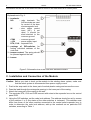
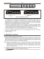
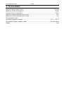
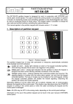
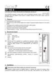
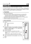
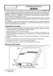
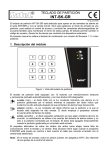
CODE LOCKS
INT-SZ-GR
INT-SZ-BL
®
f
int-sz_en 07/08
The INT-SZ-GR and INT-SZ-BL code locks are the devices designed to work in conjunction
with INTEGRA and CA-64 alarm control panels. They differ in the backlight color of their
keys, which is green in the INT-SZ-GR and blue in the INT-SZ-BL. They provide an easy way
to control access to spaces where doors with electrically-operated lock are installed, and to
control closing status of those doors. Additionally, the code locks can exercise access control
in respect of other equipment.
This manual applies to the code lock with firmware version 1.07 or later.
1. Description of code lock
The code lock has 12 keys with permanent or temporary (automatically activated) mode
backlight and LED indicators.
LED designation:
– ACTIVE (green color) – steady light
indicates that the lock is cooperating
with the control panel.
(blue color) – steady light
indicates that the code lock is
unblocked, what means that the door
can be opened.
– ACCESS
(yellow color) – steady light
indicates that the door is open.
– DOOR
Figure 1. Code lock.
Alternative blinking of all the LEDs (from top to bottom) indicates lack of communication
between the code lock and the control panel. This situation may take place when the
STARTER program is running in the control panel, or when the cable connecting the code
lock and the control panel is damaged.
2
SATEL
INT-SZ-GR/INT-SZ-BL
Information on the use of the code lock can be found in the user manual of control panel.
Explanations to Fig. 2:
1 – terminals:
NO
– relay terminals. The
NO terminals are used
for control of the door
electromagnetic lock.
IN
– door status control
input (NC). If not
used, it should be
short-circuited to the
common ground.
COM
– common ground.
+12V
– power supply input.
DTA, CLK – expander bus.
2 – package of DIP-switches for
setting individual address of the
code lock.
3 – tamper contact. The spring should
be pressed against the wall.
4 – buzzer.
Figure 2. Schematic view of the code lock electronics board.
2. Installation and Connection of the Module
Caution: Before you start to hook up the module to the existing alarm system, make sure
that the whole system is disconnected from power supply source.
1.
2.
3.
4.
Push in the snap catch in the lower part of module plastic casing and remove the cover.
Pass the lead through the rectangular opening in the lower part of the casing.
Attach the lower part of the casing to the wall.
The terminals DTA, CLK and COM connect with wires to the expander bus on the control
panel PCB.
5. Using the DIP-switches, set the code lock address. The address should be set by means
of the switches 1 to 5 (the status of the other switches is irrelevant). This address must
differ from those of the other modules connected to the control panel expander bus. In
order to determine the code lock address, add up the numbers set on particular DIP
switches, according to Table 1.
INT-SZ-GR/INT-SZ-BL
3
SATEL
Switch number
Numerical equivalent
(DIP switch in ON position)
1
2
3
4
5
1
2
4
8
16
Table 1.
address: 22
address: 6
Figure 3. Addressing examples.
6.
7.
8.
9.
Five switches make it possible to assign addresses to 32 expanders (numbers from 0 to
31). Addresses of the expanders connected to one bus may not repeat, while the
addressing sequence is optional. It is recommended to assign consecutive addresses,
starting from zero, to expanders and other modules connected to one bus. This will permit
problems to be avoided during extension of the alarm system.
Connect the module power supply to the +12V terminal. The code lock supply voltage
need not be provided from the control panel mainboard. A buffer power supply unit or
another expander with power supply may be used for this purpose. For details concerning
the cable connections see the installer manual for alarm control panels.
Connect the leads of the door status control detector to the terminals IN and COM.
Connect the leads for operation control of the electromagnetic door lock (or another
device) to the NO terminals.
Close the casing.
3. Starting the code lock
1. Switch on power supply of the alarm system.
2. Call the "Expander identification" function in the LCD keypad (¼Service mode ¼Structure
¼Hardware). After identification, the value of all settings is either zero or "None", and the
options are deactivated. Lack of key operation acknowledgement gives the impression that
the code lock does not respond to entering the password.
Note: During the identification process, the control panel saves in the module memory
a special (16-bit) number, used for checking the module presence in the system.
Replacement of the module with another one (even having the same address set on
the switches) without a new identification, will result in triggering the alarm (module
tamper – verification error).
3. Using the LCD keypad or DLOADX/DLOAD64 program, configure the code lock functions
and define the users authorized to use the given code lock.
4. Quit the service mode or the communication session with PC and save the data in the
FLASH memory.
4
SATEL
INT-SZ-GR/INT-SZ-BL
4. Programming the Code Lock Settings
The code lock can be programmed by means of the LCD keypad (¼Service mode
¼Structure ¼Hardware ¼Expanders ¼Settings ¼expander selection) or a computer with
DLOADX/DLOAD64 program. Described below are settings and options available for
programming. Abbreviations from the LCD keypad display are shown at some of the
functions in square brackets.
Figure 4. DLOADX program window with options for the code lock.
Name – makes it possible to give an individual (16-character) name to the module. In the
LCD keypad, this option can be accessed in the following way: ¼Service mode
¼Structure ¼Hardware ¼Expanders ¼Name ¼expander selection.
Partition – assignment of the code lock to a partition selected from the list.
Lock feature (DLOADX)/Lock (DLOAD64) – defines the operating mode of the lock control
relay. The control function is effected by controlling the state of NO contacts of the relay
(electromagnetic switch) installed on the board inside the code lock housing. The relay
operation is monostable. Basic state of the relay terminals is set by a separate option.
Opening the door by means of the user function ([CODE][#] or [CODE][*]) changes the
terminal status to the opposite one for a predetermined period of time.
Fixed ON time – after the door opening function is called by the user ([CODE][*]), the
relay gets activated for the "Relay ON time" and then returns to its normal state.
INT-SZ-GR/INT-SZ-BL
SATEL
5
Fixed ON time – OFF if door open [ON, openÆoff] – the relay is active until the door is
opened (the IN input disconnected from common ground), but not longer than for the
"relay ON time ".
Fixed ON time – OFF if door closed [ON, closeÆoff] – the relay is active during the time
when the door is open (the IN input cut off from the common ground) and deactivates
on closing the door (reconnection of the IN input to common ground), but not longer
than for the "relay ON time".
Relay ON time – the time period during which the relay is active. Duration of the "relay ON
time" can be from 1 to 255 seconds.
Relay – this option defines the operating mode of the relay contacts:
NO – the NO contacts are normally open, they close on activating the relay (during its
active state),
NC – the NС contacts are normally closed, they open on activating the relay (during its
active state).
Authorization control [Unauth. event] – opening the door without entering a password from
the code lock (e.g. with the key) will generate an „Unauthorized door opening” event, it
can also be signaled on the output type 93 (UNAUTHORIZED ACCESS).
Alarm on unauth. access [Unauth. alarm] – when the partition to which the module is
assigned is armed, unauthorized opening of the door will trigger the alarm and can be
additionally signaled on the output type 94 (ALARM – UNAUTHORIZED ACCESS).
Max. door open time – this option defines the time after expiry of which the module will
report the „Long opened door” event to the control panel and activate the audible alarm.
The duration can be set from 0 to 255 seconds.
Dependent on door 1 (or Dependent on door 2) – this function provides a list to choose the
door which must be closed for the lock to operate. Monitoring of the door state is
effected through the IN input in the code lock, partition keypad or CA-64 SR expander
for proximity card readers, or through the zone type 57 (TECHNICAL – DOOR MONITORING).
Two dependent doors can be selected. The function allows to create a "sluice" type
passage.
Master users/Users – this function defines master users/users authorized to use the given
code lock.
Alarms
FIRE alarm – holding down the key will trigger the fire alarm.
AUX. alarm [Medical alarm] – holding down the
key will trigger the auxiliary alarm.
PANIC alarm – holding down the key will trigger the PANIC alarm.
Silent PANIC alarm – with this option selected, triggering the panic alarm from the code
lock keypad will not set off the loud signaling; instead, a message will be sent to the
monitoring station and the output type 12 (SILENT ALARM) will be activated.
Alarm 3 incorrect codes [3 wrong codes] – entering a code unknown to the control panel
three times will trigger alarm.
Options
Partition blocking – entering the guard code when the partition is armed will temporarily
bypass the partition.
Guard round control – entering the guard code ([CODE][#] or [CODE][*]) will be recorded
as completion of the round.
Changing access code – this option enables the function of the user code changing.
6
SATEL
INT-SZ-GR/INT-SZ-BL
Signaling
Access code signaling (hardware) – enabling of this option will activate the code entry
acknowledgement signaling, which is independent of the control panel. The option is
useful in expanded alarm systems, in which there is a considerable time lag between
entering the code and generating the audible signal by the control panel.
Confirming – this option defines the way of communication between the control panel and
the code lock user:
No – the function of code keypad operation acknowledgement is disabled.
Sound – the code keypad will generate beeps as described in the user manual for the
alarm control panel.
Backlight – the audible signaling will be replaced by the blinking keypad illumination as
described in the user manual for the alarm control panel.
Backlight – defines the mode of code keypad illumination
No – keypad backlighting disabled.
Auto – keypad backlighting goes on automatically on pressing any key; the function has
additional options (submenu „Auto-backlight” in LCD keypad):
- no auto-backlight – illumination only activated by pressing one of the keys,
- zone violation – backlighting activated by pressing a key or by violation of the
selected zone,
- entry delay, partition – backlighting activated by pressing a key or by starting the
countdown of entry delay time in the indicated partition.
Note: Automatic code lock keypad illumination is ON for approx. 40 seconds from the
moment of its activation or from the last press of any key.
Permanent – code lock keypad backlighting is permanently "ON".
No auto-reset after 3 tampers – each expander automatically disables the tamper alarming
in the given expander after three consecutive (not cleared) tamper alarms. This
prevents multiple recording of the same events in the control panel memory. The option
allows this feature to be disabled.
Open door if fire [Doors on fire] – control mode for the door blocking during fire alarm:
− no – fire alarm has no effect on the door blocking,
− Partition fire alarm – fire alarm in the partition will unblock the door controlled by the
module,
− Object fire alarm – fire alarm in the object will unblock the door controlled by the
module,
− fire alarm – fire alarm in the system will unblock the door controlled by the module.
INT-SZ-GR/INT-SZ-BL
SATEL
7
5. Technical Data
Nominal supply voltage (±15%) .....................................................................................12V DC
Maximum current consumption.........................................................................................66mA
Average current consumption ...........................................................................................24mA
Maximum voltage switched over by relay ............................................................................24V
Maximum current switched over by relay...............................................................................2A
Environmental class................................................................................................................. II
Operating temperature range.............................................................................-10 °C...+55 °C
Dimensions (length x height x width) ..................................................................80x127x24mm
Weight................................................................................................................................ 110g
The latest EC declarations of conformity and certificates are available for
downloading on the website www.satel.pl
SATEL sp. z o.o.
ul. Schuberta 79
80-172 Gdańsk
POLAND
tel. + 48 58 320 94 00
[email protected]
www.satel.pl