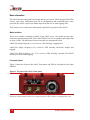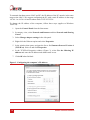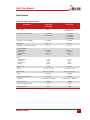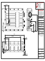
1
xNAV xF Inertial and GNSS measurement system User Manual Covers all xNAV2** and xNAV5** products Confidently. Accurately. Legal Notices Information furnished is believed to be accurate and reliable. However, Oxford Technical Solutions Limited assumes no responsibility for the consequences of use of such information nor for any infringement of patents or other rights of third parties which may result from its use. No license is granted by implication or otherwise under any patent or patent rights of Oxford Technical Solutions Limited. Specifications mentioned in this publication are subject to change without notice and do not represent a commitment on the part of Oxford Technical Solutions Limited. This publication supersedes and replaces all information previously supplied. Oxford Technical Solutions Limited products are not authorised for use as critical components in life support devices or systems without express written approval of Oxford Technical Solutions Limited. All brand names are trademarks of their respective holders. The software is provided by the contributors “as is” and any express or implied warranties, including, but not limited to, the implied warranties of merchantability and fitness for a particular purpose are disclaimed. In no event shall the contributors be liable for any direct, indirect, incidental, special, exemplary, or consequential damages (including, but not limited to, procurement of substitute goods or services; loss of use, data, or profits; or business interruption) however caused and on any theory of liability, whether in contract, strict liability, or tort (including negligence or otherwise) arising in any way out of the use of this software, even if advised of the possibility of such damage. Copyright Notice © Copyright 2015, Oxford Technical Solutions. Revision Document Revision: 150106 (See Revision History for detailed information). Contact Details Oxford Technical Solutions Limited 77 Heyford Park Upper Heyford Oxfordshire OX25 5HD United Kingdom 2 Tel: +44 (0) 1869 238 015 Fax: +44 (0) 1869 238 016 Web: http://www.oxts.com Email: [email protected] Oxford Technical Solutions xNAV User Manual Warranty Oxford Technical Solutions Limited (OxTS) warrants xNAV products to be free of defects in materials and workmanship, subject to the conditions set forth below, for a period of one year from the Date of Sale. ‘Date of Sale’ shall mean the date of the Oxford Technical Solutions Limited invoice issued on delivery of the product. The responsibility of Oxford Technical Solutions Limited in respect of this warranty is limited solely to product replacement or product repair at an authorised location only. Determination of replacement or repair will be made by Oxford Technical Solutions Limited personnel or by personnel expressly authorised by Oxford Technical Solutions Limited for this purpose. In no event will Oxford Technical Solutions Limited be liable for any indirect, incidental, special or consequential damages whether through tort, contract or otherwise. This warranty is expressly in lieu of all other warranties, expressed or implied, including without limitation the implied warranties of merchantability or fitness for a particular purpose. The foregoing states the entire liability of Oxford Technical Solutions Limited with respect to the products herein. Revision: 150106 3 Table of contents Scope of delivery 6 Introduction 7 Related documents 8 Conformance notices 9 Regulator testing standards Basic information 9 10 Model variations 10 Front panel layout 10 LED definitions 11 Co-ordinate frame conventions 12 Ethernet configuration 13 Software installation 16 Hardware installation 18 Antenna placement and orientation Configuring the xNAV 18 20 Selecting the operating language 20 Navigating through NAVconfig 20 Product selection 21 Read configuration 22 Orientation 23 Primary antenna position 24 Secondary antenna position 25 Wheel configuration 27 Options Vibration GNSS weighting Heading lock SBAS (xNAV550 only) Initialisation speed Displace output Odometer input 28 29 29 30 30 30 31 31 4 Oxford Technical Solutions xNAV User Manual Trigger 1 and Trigger 2 (xNAV5**) Serial input (xNAV5**) Serial 1 output Ethernet output (xNAV5**) Output smoothing GNSS control Altitude 1PPS Output lock Advanced 32 34 35 38 39 39 41 41 41 41 Committing the configuration 41 Saving the configuration and finishing 42 Operating the xNAV 44 Initialisation and warm-up 44 Downloading data 45 Improve the configuration with Get settings… 45 Specifications 47 Revision history 48 Drawing list 49 Revision: 150106 5 Scope of delivery Table 1 lists the standard items delivered with each xNAV. Everything required to operate the xNAV successfully is included. Please ensure everything is present upon delivery. Table 2 lists a number of optional parts that may be used with an xNAV. For more information on these components please contact your OxTS representative or email [email protected]. Table 1. Summary components supplied with an xNAV Qty. xNAV200 xNAV500 xNAV550 1 xNAV system unit xNAV system unit 2 AT575-70 GNSS antenna with 5 m cable G5Ant-2AMNS1 GNSS antenna 2 5 m GNSS antenna cable 1 User cable (14C0091F) User cable (14C0091F) 1 CD –ROM with software and manuals CD –ROM with software and manuals 4 90° mounting brackets 90° mounting brackets 1 xNAV user manual xNAV user manual Table 2. Compatible xNAV accessories Part Description RT-Strut Designed to quickly and securely provide a mounting location inside a road vehicle. RT-Strut mounting bracket Quickly attach the xNAV to an RT-Strut. RT-UPS An uninterruptible power supply capable of powering the xNAV for up to 1 minute after power is lost. Input 9–48 V dc. 6 Oxford Technical Solutions xNAV User Manual Introduction Thank you for choosing the xNAV. It is a high-performance GNSS-aided inertial navigation system designed to meet the tough demands of aerial and ground-based surveying applications—especially where space and weight are important. As a one-box solution it is quick and easy to install and configure but does not compromise on accuracy or reliability. Utilising dual antennas, DGPS corrections, tight-coupling and advanced gx/ix processing technology the xNAV delivers up to 2 cm position and 0.1° heading accuracy (2 m antenna separation) with 100 Hz output for all measurements. Up to 4 GB of navigation data (max. 2 GB per file), corresponding to over 4 days’ worth of IMU+GNSS data can be logged and stored internally and quickly downloaded via Ethernet. The xNAV500 models can output all measurements in real-time with very low latency. The xNAV200 models log data which can be post-processed later with the powerful software included with NAVsuite. This manual covers the installation, configuration and basic operation of the xNAV. Separate manuals are provided for the post-processing and graphing software of NAVsuite. An xNAV quick start guide is available on the OxTS website, but we suggest reading the entire manual in order to become thoroughly familiar with the product. It is beyond the scope of this manual to provide details on service or repair. Contact OxTS support or your local representative for any customer service related inquiries. Revision: 150106 7 Related documents There are separate manuals available for further information on some of the software and communication types mentioned in this manual. Table 3 lists related manuals and where to find them. Table 3. Supplementary manuals Manual NAVgraph Manual Description User manual for the graphing and display software NAVgraph. www.oxts.com/Downloads/Support/Manuals/NAVgraphman.pdf NCOM Manual NCOM description manual. www.oxts.com/Downloads/Support/NCOM Manual and Code Drivers/ncomman.pdf NCOM C Code Drivers A collection of C functions that can be used to decode the binary protocols from the RT. www.oxts.com/Downloads/Support/NCOM Manual and Code Drivers/ncomrx.zip NMEA 0183 Description NMEA description manual for the NMEA outputs. www.oxts.com/Downloads/Support/NMEA/nmeaman.pdf RT Postprocess Manual xNAV200 quick-start guide 8 User manual for the post-processing software RT Post-process. www.oxts.com/Downloads/Support/Manuals/rtppman.pdf Short guide going over the basics needed to quickly set up and start using an xNAV200. www.oxts.com/Downloads/Products/xNAV/130423_xNAV200 quick start guide.pdf Oxford Technical Solutions xNAV User Manual Conformance notices The xNAV complies with the radiated emission limits for 47CFR15.109:2010 class A of Part 15 subpart B of the FCC rules, and with the emission and immunity limits for class A of EN 55022. These limits are designed to provide reasonable protection against harmful interference in business, commercial and industrial uses. This equipment generates, uses and can radiate radio frequency energy and, if not installed and used in accordance with the instructions, may cause harmful interference to radio communications. However, there is no guarantee that interference will not occur in a particular installation. If this equipment does cause harmful interference to radio or television reception, which can be determined by turning the equipment off and on, the user is encouraged to try to correct the interference by one or more of the following measures: Re-orient or relocate the receiving antenna Increase the separation between the equipment and the receiver The xNAV incorporates a GNSS receiver. Any GNSS receiver will not be able to track satellites in the presence of strong RF radiations within 70 MHz of the GNSS frequencies. The xNAV conforms to the requirements for CE. Any use or misuse of the xNAV in a manner not intended may impair the protection provided. OxTS is not liable for any damages caused by the misuse of the equipment. Regulator testing standards 47CFR15.109:2010 class A (radiated emissions) EN300 440-1 v1.6.1, test methods 8.3.4 (radiated emissions) EN55022:2010 EN55024:2010 EN61326-2-1:2006 according to the requirements of EN61326-1:2006 EN61326-1-1:2013 according to the requirements of EN61326-1:2013 EN301 489-3 v1.4.1 according to the requirements of EN301 489-1 v1.9.2 IEC 61010-1:2010 3rd ed. (safety) Revision: 150106 9 Basic information The xNAV has been designed to be simple and easy to operate. The front panel and LEDs convey some basic information that aid in configuration and troubleshooting. Once powered, the xNAV requires no further input from the user to start logging data. This section covers some basic information required for operation of the xNAV. Model variations There are a number of models available in the xNAV series. All models use the same inertial measurement unit (IMU), have dual GNSS receivers as standard, and output data at up to 100 Hz. The differences between models are summarised below. xNAV200: Single frequency (L1) receivers. GPS tracking. Logging only. xNAV500: Single frequency (L1) receivers. GPS tracking. Real-time outputs and logging. xNAV550: Dual frequency (L1, L2) receivers. GPS tracking, optional GLONASS tracking. Real-time and logging. Front panel layout Figure 1 shows the layout of the xNAV front panel and Table 4 lists details of the parts labelled. Figure 1. Layout of the xNAV front panel The main connector (6) is keyed, so the user cable will only engage when correctly orientated. It is selflatching to avoid accidental removal. Do not pull on the user cable to remove it as damage may occur. 10 Oxford Technical Solutions xNAV User Manual Table 4. xNAV front panel descriptions Label no. Description 1 GNSS LED 2 Status LED 3 Pwr LED 4 Primary antenna connector 5 Secondary antenna connector 6 Main connector LED definitions Three LEDs set into the front panel of the xNAV show the system’s state when power is applied. Table 5, Table 6 and Table 7 give details on the meanings of the states of each LED. Table 5. GNSS LED states Colour Off Red flash Red Description GNSS receiver fault (valid only after start-up). GNSS receiver is active, but has been unable to determine heading. The GNSS has a differential heading lock. Orange The GNSS receiver has a floating (poor) calibrated heading lock. Green The GNSS receiver has an integer (good) calibrated heading lock. Revision: 150106 11 Table 6. Status LED states Colour Description Off The operating system has not yet booted and the program is not yet running. This occurs at start-up. Red-green flash The xNAV is asleep. Contact OxTS support for further information. Red flash The operating system has booted and the program is running. The GNSS receiver has not yet output a valid time, position, or velocity. Red The GNSS receiver has locked-on to satellites and has adjusted its clock to valid time (the 1PPS output will now be valid). The strapdown navigator is ready to initialise. If the vehicle is travelling faster than the value set for “Initialisation speed” during configuration then the strapdown navigator will initialise and the system will become active. If static initialisation has been enabled the system will initialise once the GNSS receiver has determined heading, even if the vehicle is stationary or moving slowly. Orange The strapdown navigator has initialised and data is being output, but the system is not realtime yet. It takes 10 s for the system to become real-time after start up. Green The strapdown navigator is running and the system is real-time. Table 7. Power (PWR) LED states Colour Off Description There is no power to the system or the system power supply has failed. Green Power is applied to the system. Orange The system is powered and traffic is present on Ethernet. Co-ordinate frame conventions The xNAV uses a co-ordinate frame that is popular with most navigation systems. Figure 2 shows how the axes relate to the xNAV box. All measurements to and from the xNAV should be made from the measurement origin point shown in Figure 2. The origin point is the same for all xNAV models. 12 Oxford Technical Solutions xNAV User Manual Figure 2. xNAV co-ordinate frame and measurement origin Table 8 lists the directions that the axes should point for zero heading, pitch and roll outputs when the default mounting orientation is used. Table 8. Direction of axes for zero heading, pitch and roll outputs Axis Direction Vehicle axis x North Forward y East Right z Down Down If the axes of the xNAV and the vehicle axes are not the same as those listed in Table 8, then they can be aligned by reconfiguring the xNAV for a different mounting orientation using the NAVconfig software. If the RT-Strut is being used to mount the xNAV in the vehicle then NAVconfig will have to be used to configure the orientation or the xNAV will not work correctly. Page 23 gives more information on configuring the orientation of the xNAV in a vehicle. Ethernet configuration The xNAV communicates primarily via Ethernet. In order to communicate via Ethernet, each xNAV is configured with a static IP address that is shown on the delivery note. If the delivery note is unavailable, the default IP address normally takes the form 195.0.0.sn—where sn is the last two digits of the xNAV’s serial number. The serial number can be found on the bottom of the xNAV or on the delivery note. Revision: 150106 13 To transmit data between an xNAV and PC, the IP address of the PC must be in the same range as the xNAV. We suggest configuring the PC with a static IP address in the range 195.0.0.1 to 195.0.0.10 and a subnet mask of 255.255.255.0. To change the IP address of the computer, follow these steps (applies to Windows Vista/7/8): 1. Open the Control Panel from the Start menu. 2. In category view, select Network and Internet and then Network and Sharing Center. 3. Select Change adapter settings in the side panel. 4. Right-click the Ethernet option and select Properties. 5. In the window that opens, navigate the list to find Internet Protocol Version 4 (TCP/IPv4). Select it and click Properties. 6. In the TCP/IPv4 Properties window (Figure 3), select Use the following IP address and enter the IP address and subnet mask to use. 7. Click OK when finished. Figure 3. Configuring the computer’s IP address 14 Oxford Technical Solutions xNAV User Manual Once the computer is configured the IP address of an xNAV can be found by running Enginuity software; this will display the IP address of any system connected. Note that it is possible to change the IP address of xNAV systems. If the IP address has been changed then Enginuity should still be able to identify the address that the xNAV is using as long as the PC has a valid IP address and this is not the same as the xNAV’s. Revision: 150106 15 Software installation Included with every xNAV is a CD containing the software package NAVsuite. This package contains a number of programs required to take full advantage of the xNAV’s capabilities. Table 9 lists the contents of NAVsuite. Table 9. Installed software components Icon Software Enginuity Description Used to view real-time data from OxTS products via Ethernet or a serial port. It can also be used to transmit special commands and replay logged data. Note: Only the xNAV500 models are capable of real-time outputs. Enginuity will not display any data in real-time with the xNAV200s. NAVdisplay (beta) Replacement for Enginuity. Features the same functionality with an updated GUI and improved usability. NAVconfig Used to create, send, and receive configurations from OxTS products. As configurations vary between products there is no manual for NAVconfig. The options relevant to the xNAV are covered in this manual on page 20. RT Post-process Used to download raw data files from the xNAV and postprocess the data. The configuration can be changed and differential corrections can be applied before the data is reprocessed. It can export NCOM, XCOM and CSV file formats. NAVgraph Used to graph NCOM, XCOM and RCOM files created in post-process. It can display graphs, cursor tables and map plots and data can be exported in CSV or KML (Google Earth) format. Manuals This folder contains PDF versions of relevant OxTS manuals. Other manuals can be downloaded from the OxTS website, http://www.oxts.com/support/manuals/. To install NAVsuite, insert the CD and run NAVsetup.exe. Follow the onscreen instructions to install the software. By default the installer creates the program files in C:\Program Files (x86)\OxTS on 64 bit operating systems or C:\Program Files\OxTS on 32 bit operating systems. The first time some OxTS applications are run a firewall warning message similar to that shown in Figure 4 may be triggered. This is because the program is attempting to listen for, and communicate with, OxTS devices on the network. The firewall must be configured to allow each program to talk on the network, or programs will not work as intended. 16 Oxford Technical Solutions xNAV User Manual Figure 4. Windows Firewall warning message A firewall warning message may be triggered the first time OxTS software is run. Access must be allowed for each application that requires it, or the program cannot work properly. Sometimes a warning will not be triggered but the firewall may still block certain functions. If a program fails to display the IP address of a connected xNAV check the firewall settings for that connection. Ensure both Private and Public networks are selected to ensure the software can continue functioning when moving from one type to another. Revision: 150106 17 Hardware installation Installing the xNAV is not difficult, but it is a precision instrument and care should be taken not to subject it to extreme shock, vibration or temperature. Bear in mind the minimum clearance required for the antenna connectors and user cable is 39 mm from the front panel (see Figure 5). Figure 5. Clearance required for connectors and user cable When mounting the xNAV a minimum of 39 mm is required for the user cable. At the minimum distance, it will not be possible to remove the main connector without also uninstalling the xNAV. The xNAV does not need to be located at the desired measurement point as the outputs can be displaced using NAVconfig. However, any displacement should try to be kept to a minimum. Once configured, the xNAV’s output will appear the same as if it was mounted at the displaced location. It is essential to install the xNAV rigidly in the vehicle. It should not be able to move or rotate compared to either GNSS antenna, otherwise the performance will be reduced. The xNAV is compatible with the RT-Strut product from OxTS when used with additional mounting brackets. The RT-Strut can be used to provide a quick and secure vehicle mounting option. The orientation of the xNAV’s local axes is shown on page 13. For ease of use it is best to try and mount the xNAV so its axes are aligned with the vehicle axes. If the system must be mounted misaligned with the vehicle then the offsets must be measured and entered into NAVconfig. This allows the outputs to be rotated based on the settings entered to transform the measurements to the vehicle frame. Antenna placement and orientation The placement and orientation of the GNSS antennas is important to the system accuracy. For optimal performance it is essential for the antennas to be mounted where they have a clear, uninterrupted view of the sky and on a suitable ground plane, such as the roof of a vehicle. For good multipath rejection the antennas must be mounted on a metal surface using the magnetic mounts provided; no additional gap may be used. The antennas cannot be mounted on non-conducting materials or near the edges of conducting materials. If the antennas are to be mounted with no conductor below them 18 Oxford Technical Solutions xNAV User Manual then different antennas must be used. It is recommended to mount the antennas at least 20 cm from any edge where possible. Antennas should be spaced between 1 m and 5 m apart and the antenna baseline should be aligned with one of the vehicle axes where possible, either inline or perpendicular to the vehicle’s forward axis. It is possible to use a shorter antenna separation but the heading accuracy will degrade. When mounting the antennas, the secondary antenna should be mounted in the same orientation as the primary, as shown in Figure 6. The direction the cable exits the antennas does not matter as long as it is the same for both. Figure 6. Antenna placement A) The bases of the antennas are parallel, but the cables exit in different directions. B) The cables exit in the same direction but the bases of the antennas are not parallel. C) The bases of the antennas are parallel and the cables exit in the same direction. This configuration will achieve the best results. When measuring the antenna separation, if the antennas are level (i.e. within 15° of horizontal) then the separation should be measured to within 5 cm. If the antennas are not level then the separation must be measured to 5 mm. Revision: 150106 19 Configuring the xNAV To obtain the best results from your xNAV it will be necessary to configure it to suit the installation and application before using it for the first time. The program NAVconfig can be used to do this. This section describes how to use NAVconfig and gives additional explanations on the meanings of some of the terms used. It is only possible to change the xNAV configuration using Ethernet. It is necessary to have the Ethernet on your computer configured correctly in order to communicate with the xNAV and change the settings. See the section “Ethernet configuration” on page 13 for more information. The configuration file defines where the xNAV is and how it is orientated in relation to the host being measured. It also specifies any options to use while processing the data. Once a configuration has been committed to the xNAV, it will remain there and the system will use that configuration each time on start up. There is no need to reconfigure it unless the xNAV or an antenna is moved. Selecting the operating language The NAVconfig software can operate in several languages. To change language, select the language from the drop-down menu at the bottom of the page. The language is “hotswappable” making it easy and fast to switch between languages. The software will use the regional settings of the computer to choose whether numbers are represented in the English or European format (dot or comma for the decimal separator). The selected language does not change the format used for numbers. Navigating through NAVconfig NAVconfig provides a ten-step process to make configuring your product as easy as possible. After completing each step, click the Next button at the bottom of the window to proceed to the next step. The Back button can be used to return to the previous step at any time. Clicking Cancel will bring up a warning asking to confirm you want to close the wizard and lose any changes you have not saved. To quickly move between any of the steps, click on the step name in the sidebar to instantly jump to that page. Measurements are always displayed in metric units in NAVconfig. However, when entering measurements alternate units can be used as long as they are specified, e.g. 10” or 10 in. NAVconfig will then convert and display these in metric units. 20 Oxford Technical Solutions xNAV User Manual Product selection NAVconfig is a universal application used to configure several different OxTS products. The first page of the configuration wizard (see Figure 7) tells the application what type of sensor is being configured. The program then loads the correct options specific to that device. Figure 7. NAVconfig Product Selection page The configuration wizard can be run without a system connected so it is necessary to select the correct product for configuration. Some configuration pages are not available with some of the products. These will be displayed as grey in the sidebar. In instances where the same product type will be used each time, the Product Selection page can be skipped in the future by clicking the Always use this product checkbox. If a different product needs configuring, the selection page can be returned to by clicking Product Selection in the sidebar Revision: 150106 21 Read configuration The Read Configuration page gives several options for reading the configuration from different places as shown in Figure 8. Figure 8. NAVconfig Read Configuration page Use default settings: When configuring a new installation, this option should be selected. This forces NAVconfig to load a clean set of base settings, removing any advance features that may have been previously committed. Read settings from a folder: It is possible to store a configuration in a folder. The configuration requires several files so it is tidier to keep it in a folder by itself. To read the configuration from a folder select this option and specify a folder by clicking the Browse… button. Read settings from an RD file: The xNAV writes the configuration it is using to the internally stored RD file. This option extracts the configuration used for that data set and loads it in the configuration wizard. Specify an RD file by selecting this option and clicking the Browse… button. 22 Oxford Technical Solutions xNAV User Manual Read initial settings from xNAV: If the xNAV is connected to the computer via Ethernet then it is possible to read the initial settings directly from the xNAV. The settings loaded are the settings that were last committed to the xNAV. Select this option and enter the IP address of your xNAV or select it from the drop-down list. The list will show all systems that are connected to the network, so if more than one is connected ensure you select the correct system. Note: the list will not function correctly if Enginuity or other software is using the xNAV UDP port unless the OxTS UDP Server is running. Orientation The Orientation page, shown in Figure 9, is where the host vehicle co-ordinate frame is defined relative to the xNAV’s co-ordinate frame. It is important to get the orientation correct as although settings entered on this page do not affect the accuracy of the xNAV, if the outputs are not properly rotated to the vehicle frame then the measurements will appear incorrect. Figure 9. NAVconfig Orientation page To define how the xNAV is mounted in the host vehicle it is necessary to tell NAVconfig which direction two of the xNAV’s axes point. Select the correct option for Y axis points Revision: 150106 23 and Z axis points from the drop-down lists. The greyed out advanced settings will change to show the three rotations associated with orientation chosen. If it is not possible to mount the xNAV squarely to the host’s co-ordinate frame, select Use advanced settings and define the xNAV’s orientation using these values. For correct initialisation it is necessary to get the heading orientation correct. The xNAV gets its initial heading by assuming that the vehicle is travelling forwards in a straight line. If the definition of the vehicle’s x-axis (forward direction) is incorrect then it will not initialise correctly when the vehicle moves forwards. In permanent installations, the Get settings… button can be used to import improved settings from a previously post-processed raw data file. Details of the process are given on page 45. Primary antenna position Accurately defining the position of the primary antenna in NAVconfig helps achieve better results sooner. It is recommended to measure the GNSS antenna position to an accuracy of 10 cm or better. Measure the distances from the xNAV to the GNSS antenna along each of the axes in the vehicle’s co-ordinate frame. On the Primary Antenna page, shown in Figure 10, select the directions (Ahead/Behind, Right/Left, and Above/Below) and enter each of the measurements. For visual confirmation the position of the antenna in the image will change to reflect the specified configuration. The Overall accuracy can be specified by choosing a value from the drop-down list or typing one in. Alternatively the accuracy of each measurement can be specified separately by clicking the checkbox to unlock the greyed out drop-down boxes. The default accuracy is 10 cm which is sufficient for the xNAV to refine itself to specification during the warm-up period. Care should be taken if specifying a greater accuracy. Do not overstate the accuracy as doing so may cause the xNAV to look in the wrong place, increasing the time taken to find the correct solution. 24 Oxford Technical Solutions xNAV User Manual Figure 10. NAVconfig Primary Antenna page Secondary antenna position The Secondary Antenna page, shown in Figure 11, is used to define the position of the GNSS antenna connected to the secondary receiver, relative to the primary one. The secondary antenna should be placed in accordance with the information given in the installation section on page 18. Ensure to click the Enable secondary antenna checkbox to allow the configuration to be entered. If it is not enabled, the xNAV will ignore the secondary antenna and will not use it to compute a heading solution. By default the Antennas are level box is checked. This means the antenna baseline should be within 15° of horizontal. When the antennas are level the separation should be measured to within 5 cm. If the antennas are not level, i.e. mounted with height offsets or on an incline, then the box should be unchecked. In this case, the separation should be measured to within 5 mm. Enter the antenna separation and select the position of the secondary antenna relative to the primary antenna from the drop-down list. The measurement accuracy can also be Revision: 150106 25 specified with the to within drop-down box. The illustrations will change according to the settings you choose to help visualise the configuration of the antennas. Figure 11. NAVconfig Secondary Antenna page It is important to measure between the same point on each antenna, e.g. centre to centre, or from cable to cable. If the antennas are mounted at significantly different heights, or if the mounting angle is not directly along a vehicle axis (forward or right), then click the Use advanced settings checkbox to enable advanced settings and specify the orientation and height offset. The Enable static initialisation option is useful for slow moving vehicles or when dynamic initialisation may be difficult. Static initialisation is 99% reliable in open sky, but the reliability decreases in environments with high multipath. Static initialisation is also faster when the antenna separation is smaller and the Antennas are level checkbox is ticked. 26 Oxford Technical Solutions xNAV User Manual Wheel configuration The Wheel configuration feature uses characteristics of land vehicle motion to improve heading and reduce drift. Specifying the position of the non-steered wheels on the Wheel Configuration page (Figure 12) makes a huge difference to the lateral drift performance of the xNAV when GNSS is not available. This feature must be disabled for airborne and marine applications where the lateral velocity can be significant. It is also not suitable for land vehicles that have no nonsteered wheels. Figure 12. NAVconfig Wheel Configuration page To enable this feature for land vehicles with a non-steered axle, click The vehicle has a non-steered axle checkbox. The system needs to know the position of the non-steered axle (rear wheels on a front-wheel steering vehicle and vice versa). Vehicles with all wheels steering cannot use this feature reliably, although minor steering of the rearwheels does not significantly affect the results. The measurements entered are from the xNAV’s measurement point, to the point shown in Figure 13. Revision: 150106 27 Figure 13. Measurement point for wheel configuration Measure the distances to the non-steered axle position in each axis in the vehicle coordinate frame. Select the direction from the drop-down lists and enter the distances. Typically the measurements should all be made to an accuracy of 10 cm. Selecting an accuracy better than 10 cm does not improve results. Using an accuracy figure worse than 20 cm will increase the drift of the xNAV. Use the accuracy fields to select or specify the accuracy of the measurements. The Wheel configuration feature also requires some knowledge of the road surface. Select one of the predefined options from the drop-down list, Normal or Low friction (ice). Options The Options page includes some important settings for getting the best results from your xNAV. Figure 14 shows the options available for the xNAV550. Some options are not available on other models. To adjust the settings, click the default value in the Setting column to activate the cell. A description on each option and how to adjust it is found below. The Serial 1 output and 1PPS options are the only options to affect the real-time operation of the xNAV2** models. All other options are used during post-processing only. The xNAV5** models output data in real-time so the options configured here will affect the real-time operation. The options can also be changed later in post-processing. 28 Oxford Technical Solutions xNAV User Manual Figure 14. NAVconfig xNAV550 Options page Vibration There are three options available to describe the level of vibration the system will be exposed to. In most cases Normal, will work correctly. If the xNAV is installed using vibration mounts allowing some movement independent of the GNSS antennas, High or Very high settings should be considered. Select the appropriate option from the dropdown list. GNSS weighting The xNAV can place different emphasis on the GNSS receiver’s measurements. The default setting is Medium, placing equal weighting on the GNSS receivers and inertial sensors. Selecting High from the drop-down list will cause the xNAV to believe the GNSS receivers more and selecting Low will make the xNAV rely more on the inertial sensors. In urban environments it is better to believe the inertial sensors more whereas in open sky the GNSS receiver should be believed more. Revision: 150106 29 Heading lock When stationary for extended periods of time, the heading of single antenna systems can drift. The heading lock option solves this by locking the xNAV’s heading to a fixed value while the system is stationary. Using the dual antenna system will also keep the heading stable in which case heading lock is not necessary. Heading lock cannot be used with host vehicles that can turn on the spot (i.e. without longitudinal velocity). Note that simply turning the steering wheel while stationary is often enough to change the heading on most road vehicles. Select an option from the drop-down list. Table 10 gives a description on each of the heading lock options. Table 10. NAVconfig heading lock options Heading lock Description Disabled Disables heading lock. Should be used if the vehicle can turn on the spot. Normal Best for most applications. Assumes that the heading of the vehicle does not change by more than 2° while the vehicle is stationary. The heading accuracy recovers quickly when the vehicle moves. Tight Assumes that the heading of the vehicle does not change by more than 0.5° while the vehicle is stationary. The recovery is fast if the heading of the vehicle does not change but will be slow if the vehicle turns before it moves. Very tight Assumes that the heading of the vehicle does not change by more than 0.3° while the vehicle is stationary. The recovery is fast if the heading of the vehicle does not change but will be slow if the vehicle turns before it moves. This option can cause problems during the warm-up period if the vehicle remains stationary for a long time and then drives suddenly. SBAS (xNAV550 only) When operating in a region with a satellite based augmentation service (SBAS), enabling this option will improve the GNSS performance compared to standard positioning service (SPS). Services currently supported are Europe (EGNOS), North America (WAAS), Japan (MSAS), India (GAGAN), and Russia (SDCM). Initialisation speed If static initialisation has not been enabled, the xNAV will need to be initialised by moving forwards in a straight line. When the vehicle exceeds the initialisation speed the roll and pitch measurements are assumed to be zero (with a large error), and the heading is approximated to the vehicle’s course over ground. 30 Oxford Technical Solutions xNAV User Manual The default speed of 5 m/s is suitable for most applications. It can be changed by selecting a predefined option from the drop-down list or by typing in a custom value. Displace output The xNAV can displace or move its outputs to another location in the vehicle. This simulates the xNAV being mounted at the new location. This function displaces all of the outputs (position, velocity, acceleration) to this new measurement point. In high vibration environments, any displacement should be kept to a minimum. Click the button to open the properties window, click the checkbox and enter the offsets to the new location in the vehicle. The offsets are measured from the xNAV in the vehicle co-ordinate frame. Select the directions from the drop-down lists. The images will change to help visualise the displaced measurement point of the xNAV. Odometer input In land-based survey applications, the xNAV’s accuracy can be maintained for longer periods during GNSS blackouts if an independent wheel speed odometer is fed into the system. To configure an odometer input, click the button to open the properties window, shown in Figure 15. Ensure the checkbox is clicked, since if this option is disabled the xNAV will ignore corrections from the odometer even if one is connected. It is essential to use the Wheel configuration feature (page 27) at the same time as an odometer input. As with the wheel configuration, an odometer input can only be used on land vehicles. It must not be used on a steered wheel, the odometer should be on a wheel that is measuring the forward direction of the vehicle. For best results, a front wheel drive vehicle should be used with the odometer on a rear wheel. The odometer pulses from driven wheels are less accurate. The distances from the xNAV to the measurement point of the odometer in the vehicle co-ordinate frame should be input. The directions can be selected from the drop-down lists. If the odometer is from a prop shaft then the distance should be measured half way between the two wheels. The illustrations in the window will change depending on the settings you choose, to help visualise the position of the xNAV in relation the odometer. The pulses per metre should also be specified. A value that is accurate to 10% is sufficient unless the figure is known more accurately. The xNAV will improve this scaling factor itself when GNSS is available. The xNAV also supports quadrature inputs. The Directional odometer checkbox should be selected to enable this feature. Revision: 150106 31 Figure 15. NAVconfig odometer input properties window Trigger 1 and Trigger 2 (xNAV5**) The xNAV5** models have 2 triggers that can be configured as either input triggers, output triggers, or an IMU sync pulse. To enable a trigger, click the button to open the properties window, shown in Figure 16. Select the trigger type from the drop-down list. 32 Oxford Technical Solutions xNAV User Manual Figure 16. NAVconfig trigger properties window Input: Accepts a trigger input from an external device, such as a camera shutter, to generate a data point with all measurements at the exact timestamp of the trigger. The event input has a pull-up resistor so it can be used with a switch or as a CMOS input. The input sees less than 0.6 V as low and more than 2.6 V as high. The input range should be kept between 0 V and 5 V. Output: Generates a pulse based on distance. Select the distance interval to generate the pulses on from the drop-down list, or type in a value. The output has 0.8 V or less for a low and 2.4 V or more for a high. The pulse width is 1 ms. By selecting Rising edge or Falling edge from the drop-down box the trigger can be configured as a low or high, as illustrated in Figure 17. Revision: 150106 33 Figure 17. Output trigger settings IMU sync: Generates a 100 Hz output pulse synchronised to the IMU sample time. The output has a duty cycle of approximately 50% and the falling edge is synchronised to the sample file of the data from the IMU. Serial input (xNAV5**) The transmit and receive functions on the xNAV5**s’ serial port can be configured separately. The serial input can be used to either receive differential corrections or to receive commands. To configure the serial port input, click the window, shown in Figure 18. 34 button to open the serial input properties Oxford Technical Solutions xNAV User Manual Figure 18. NAVconfig serial input properties window Select the input type from the drop-down list. The settings will then appear for customisation. If configuring the input for differential corrections, the Correction type drop-down list will appear as an extra option. The xNAV products can accept RTCMV3 format corrections. The other options can be customised to fit the type of base station being used. The default options are compatible with the OxTS RT-Base and GPS-Base. Serial 1 output When using the serial port output, it can be configured for different message types. Click the button to open the properties window, shown in Figure 19. Revision: 150106 35 Figure 19. NAVconfig serial output properties Select the message type to output from the Packet drop-down list and select the output baud rate and data rate. Table 11 gives details of the different messages. If the NMEA packet type is selected, the NMEA tab will appear in the properties window (see Figure 19). In this tab the NMEA messages to output on the serial port are selected by choosing the data rate for each message type from the drop-down lists and clicking the checkbox for when to generate the message. Note: The xNAV200 does not calculate measurements in real-time so cannot output any measurements over Ethernet or serial. However, there are two NMEA messages that can be configured to be output over serial on the xNAV200: GPGGA and GPZDA. These are the GPS Fix Data and Date & Time sentences, respectively, and are limited to 4 Hz. NMEA messages can be generated by falling or rising voltages on the event input trigger. Check the falling or rising edge checkbox to compute the message when the event occurs. The xNAV500s can also generate NMEA messages from pulses on the output trigger. These messages use interpolation to compute the values at the exact time of the event but may be output on the serial port up to 30 ms late and out of order compared to the normal messages. To enable these messages check the appropriate checkbox. 36 Oxford Technical Solutions xNAV User Manual Table 11. Serial output options Option Description Disabled The serial output is disabled. This option can be used to reduce the computational load and ensure that the Kalman filter runs quicker. NCOM Normal output of the xxNAV. NCOM data is transmitted at up to 100 Hz. The format is described in the NCOM Description Manual. Software drivers exist for decoding the NCOM data. IPAQ NCOM output at a reduced rate. The baud rate of the serial port is set to 19200 and the update rate is 25 Hz. It is used because the IPAQ cannot manage to receive the data reliably above 25 Hz. IPAQ+ NCOM output at a reduced rate and polled. Windows Mobile 5 on IPAQs crashes if the xNAV is sending data when the IPAQ is turned on. Using IPAQ+ the IPAQ will poll the xNAV; the xNAV will not send data while the IPAQ is off, preventing the turn-on crash of the IPAQ. NMEA The NMEA outputs conform to the National Marine Electronics Association Standard (NMEA 0183 version 3.01). The NMEA sentences available are GPGGA, GPHDT, GPVTG, GPZDA, GPGST, PASHR, GPRMC, GPGSV, GPGSA, PTCF, GPPPS, PRDID, GPROT, GPGGK, and GPUTC. The NMEA 0183 description manual gives details of the fields output in the NMEA sentences. Javad I+RTK A special set of messages output in GREIS format to be used with Javad receivers. For assistance please contact OxTS for support. MCOM TSS1 TSSHHRP Used for marine applications. Identical to NCOM output but with the addition of heave measurements. TSS1 format outputting acceleration, heave, roll and pitch. TSSHHRP format. EM3000 Suitable for use with Simrad EM3000 multibeam sounders. EM1000 Suitable for use with Simrad EM1000 multibeam sounders. Note that it is easy to overload the serial port if there are too many events. The software computes the number of characters that will be output each second and displays this at the bottom of the window. A serial port data overflow warning message will appear if the data rate is too high for the selected baud rate; to fix this it is necessary to lower the data rate of the selected NMEA sentences or increase the baud rate. Selecting Allow extended length messages enables the full GGA and RMC messages to be output, which are longer than the NMEA specification allows. Please see the NMEA 0183 Description manual for more details. Selecting Output approximate values before initialisation forces output of the raw GNSS measurements before the xNAV is initialised. Currently just the position is output and this is the position of the antenna, not the inertial measurement unit. Note that there will be a jump (from the antenna to the inertial measurement unit) when initialisation occurs. Revision: 150106 37 Ethernet output (xNAV5**) Ethernet is the default setting to output measurements. It can be configured for different data rates and to output extra data packets based on triggers. Click the open the properties window, shown in Figure 20. button to Figure 20. NAVconfig Ethernet output properties window The Ethernet output can either output NCOM or MCOM, or be disabled by using the Output Packet drop-down list. When NCOM or MCOM is selected, the Data rate can be selected by using the drop-down list. If a trigger has been configured as an event input, click the Output on falling edge of trigger or Output on rising edge of trigger checkboxes to choose when the extra data packet is generated. If a trigger has been configured as an output trigger, click the Output on camera trigger to generate extra data packets based on the output trigger settings configured earlier. These packets are interpolated to the time when the event occurred and may be output up to 30 ms late and out of order compared to the normal messages. It is essential to enable these options in order to see trigger information in NCOM, or if the events have a rate higher than 1 Hz otherwise the output cannot communicate all of the events and some will be lost. The Delay output option should not be used with the xNAV. 38 Oxford Technical Solutions xNAV User Manual Output smoothing When the Kalman filter in the xNAV determines that there is some error to correct, this error is applied smoothly rather than as a jump. The output smoothing controls how fast the correction is applied to the outputs. Click the button to open the properties window and click the checkbox to enable output smoothing. The smoothing of the position, velocity and orientation corrections can be controlled independently. The Smoothing parameters define the maximum amount of correction applied per second. The Time limit forces a correction if the correction will take more than the specified time. Care should be taken not to make the smoothing too small. If these parameters are too small then the xNAV will not be able to make suitable corrections to the outputs and it will not work correctly. Note: this function is designed to improve the data in real-time. Since the xNAV200 is post-process only, this option should only be used when using the “simulated” postprocessing option. When processing with the forwards-backwards “combined” option, output smoothing should not be used as it may give unexpected results. There is an option in RT Post-process for “Advanced smoothing” that is designed to work with combined processing. GNSS control The GNSS control option contains advanced options that control how the GNSS information is managed in the xNAV. Click the button to open the properties window. The GNSS algorithm tab (Figure 21a) can be used to select the algorithm used for blending the GNSS and the inertial data in the Kalman filter. The Recovery tab (Figure 21b) can be used to decide how to begin using GNSS measurements if they have been rejected or ignored for a period of time. Use OxTS gx/ix raw data processing algorithm enables gx/ix™ mode. The gx/ix processing uses the raw data from the GNSS and custom algorithms to compute position and velocity tailored to the needs of the Kalman filter. It also improves performance in poor GNSS environments using single satellite aiding technology and tightly coupled GNSS and inertial measurements. gx/ix mode is recommended to achieve the highest accuracy in environments where signal lock may be difficult to maintain, e.g. urban canyons. gx/ix mode is not currently compatible with all GNSS modes. Table 12 details the current compatibilities of gx/ix mode. Revision: 150106 39 Table 12. gx/ix compatibility GNSS mode Real-time Post-process SPS SBAS x x DGPS RTK x With gx/ix RTK upgrade GLONASS x x The Use GNSS receiver’s calculations option turns off gx/ix mode and uses the receiver’s default algorithms for calculating a GNSS solution. Figure 21. NAVconfig GNSS control properties window (a) (b) The Recovery tab controls how the xNAV will accept or reject GNSS measurements. The GNSS control determines how many updates the xNAV should ignore before forcing the GNSS to be accepted. Both the velocity and the position can be controlled separately. In the default state the xNAV will reject up to 20 GNSS measurements before it forces the GNSS to be accepted. However, in high multipath environments or when wheel speed measurements are used, it may be desirable to reject more GNSS measurements. Select 40 Oxford Technical Solutions xNAV User Manual the Start believing measurements after_ option and enter the number of GNSS measurements to reject before the system starts believing it again. The xNAV GNSS receivers update both position and velocity at a rate of 5 Hz. Therefore to ignore updates for 60 s for example, the number to enter to start believing measurements again would be 300. The gx/ix processing algorithm makes its own decisions about when to trust, and how to recover from GNSS errors, so Use firmware defaults should be selected when using gx/ix mode. Altitude The altitude output by the xNAV can be compared to the WGS 84 (ITRF05) ellipsoid or to the EGM96 geoid. By default the ellipsoidal model is used. To change to a geoidal altitude simply select it from the drop-down list. Alternatively, a constant offset to the WGS 84 ellipsoid can be applied by typing in a value into the cell 1PPS A one-pulse-per-second signal from the primary GNSS receiver is output when a valid GNSS solution is found. The output is a low-voltage CMOS output where 0.8 V or less represents low and 2.4 V or more represent high. No more than 10 mA should be sourced from the output. The GNSS time crossing boundary can be configured to coincide with the rising or falling edge of the signal. Output lock The output of the xNAV will continue to change even when the vehicle is stationary. For some systems this leads to ambiguous results. The position and orientation can be “locked” by the xNAV automatically when the vehicle becomes stationary. While the outputs are locked, the Kalman filter continues to run and accumulate errors. When the vehicle moves, the Kalman filter will quickly return to the new solution. The drift rate can be controlled using the Output smoothing option. Advanced Clicking the button opens the Advanced settings window. This can be used to set special commands for the xNAV. This should only be done with special instructions from OxTS. Committing the configuration NAVconfig is an off-line configuration tool, so configurations must be explicitly uploaded to the xNAV via Ethernet when finished. On the Commit page (Figure 22) enter Revision: 150106 41 the IP address of the xNAV that you want to configure or select it from the drop-down list. The drop-down box will list all of the systems that are connected to the computer’s network so ensure to select the correct system if there are multiple listed. The list will not work if Enginuity or other software is using the xNAV UDP port unless the OxTS UDP server is running. Click Commit to save the configuration to the xNAV. This will automatically reset the xNAV so the changes take effect. It will be necessary to initialise and warm-up the system again after the changes have been applied. Figure 22. NAVconfig Commit page Saving the configuration and finishing Before finishing it is possible to save a copy of the configuration in a folder on your computer. This can then be easily loaded back into the system if using the same configuration again. The Save/Finish page also lets you know if the settings have been committed successfully or not. Figure 23 shows the Save/Finish page. 42 Oxford Technical Solutions xNAV User Manual Figure 23. NAVconfig Save/Finish page To save a copy of the configuration in a local folder check the Save settings in the following folder box and use Browse… to select a folder. The configuration has a number of files associated with it so it is recommended to create a new folder. Click Finish to save the configuration to the selected folder and close NAVconfig. Revision: 150106 43 Operating the xNAV Initialisation and warm-up For a short period after powering on, the xNAV will not conform to specification. The Kalman filter requires data in order to tighten its model of the system. This applies to both real-time accuracy and post-processed data. When powering up the xNAV, the normal procedure should be to wait until both primary and secondary GNSS receivers achieve a position fix. If static initialisation has been enabled, the xNAV will then use the dual antenna system orientation to initialise heading. If not, once GNSS lock is achieved the vehicle should move forwards and in a straight line exceeding the initialisation speed set in NAVconfig. This will approximate the heading to course over ground. Roll and pitch are estimated over the first 40 s of motion. At this point the xNAV is initialised, but will still benefit from a warm up to improve its accuracy. To provide that information, it is necessary to excite the accelerometers and gyros in all axes. For land vehicles, this means driving figures of eight with some acceleration and braking. In the case of aerial vehicles, the system should be flown in a similar way, but with the addition of climbs and dives. This warm up process should take about five minutes. For xNAV5** models, Enginuity can be used to verify the system is working correctly. For xNAV2** models there are no real-time navigation outputs to check the system, so the data should be downloaded using the RT Post-process utility and processed to verify correct operation of the system. Once the system has warmed up it should be left with power applied. Turning off the xNAV will require the warm up process to be repeated. The process from initial power on to conducting the first test is summarised below: 1. Turn the system on. 2. Wait for the primary and secondary GNSS receivers to achieve fix. 3. Move forwards in a straight line, exceeding the initialisation speed. 4. Move for about five minutes, exciting the accelerometers and gyros in all axes. 5. Check the measurements in real-time or download the data and verify correct operation. 6. Conduct tests. 44 Oxford Technical Solutions xNAV User Manual Downloading data Once measurements have been collected with the xNAV the data is downloaded to a PC using RT Post-process. A full explanation of RT Post-process is given in the RT Postprocess manual. It should be noted this manual was written before the xNAV existed and only talks about the RT systems. RTs work just like the xNAV but are larger and output real-time data. Otherwise the download and post-processing of data is the same. Improve the configuration with Get settings… During the warm-up period, the system tries to improve some of the configuration parameters that were originally specified in NAVconfig. In particular it tries to improve the GNSS antenna position, orientation of the dual antennas, yaw orientation of the xNAV in the vehicle and the wheel speed values if used. The Get Settings… button is located on the Orientation page of NAVconfig. The button provides a way of importing these improved settings directly into NAVconfig, by reading them from a correctly warmed up system or a forward processed NCOM file. The new and improved parameters can then be uploaded to the xNAV and used during subsequent data collection or post-processing applications. This feature should not be used if there is a risk the xNAV will rotate in the vehicle or that the GNSS antennas can move – even by a few millimetres. It is possible to select which parameters are updated during Step 2 of the Get settings from xNAV window shown in Figure 24. Figure 24. Get settings windows Click the drop-down list and choose which source to read the configuration from. The two options are: Read configuration from file. If an NCOM file has been saved to disk, or processed using the post-process utility then this file can be read and the settings extracted from it. Use this setting if you have a forward processed NCOM file. Revision: 150106 45 Click Browse… and select the NCOM file you wish to read the configuration from. Do not use an NCOM file that has been combined from forward and backwards processing of the inertial data. Read configuration from Ethernet (xNAV5** only). This will get the information that the xNAV is currently using and apply it next time the system starts. Use this setting if the xNAV is running, has initialised and has warmed up. Select the correct IP address of the xNAV to read the configuration from in the drop-down list. Note: the list will not function correctly if Enginuity or other software is using the xNAV UDP port unless the OxTS UDP Server is running. Once the source has been selected, click Next and the software will find which settings can be obtained from the source. Settings that cannot be obtained will be shown in grey; this may be because the xNAV is not calculating these values at present. Select the settings you want to be updated and uncheck the ones that you do not want to update. Click Finish to transfer these settings to the configuration wizard. If Orientation in vehicle is selected, the improvement to orientation should only be applied if the change in the orientation is small (less than 5°). If the change in orientation is large then it is likely that the original configuration was wrong or has not been loaded into NAVconfig. You are very likely to get poor results if the orientation is changed by a large amount. 46 Oxford Technical Solutions xNAV User Manual Specifications Table 13. xNAV specification Parameter xNAV200 xNAV500 xNAV550 GPS L1 GPS L1, L2 GLONASS L1, L2 Position accuracy (CEP) 2 m SPS 0.5 m DGPS 1.6 m SPS 0.6 m SBAS 0.4 m DGPS 0.02 m RTK Velocity accuracy (RMS) 0.1 km/h 0.1 km/h Roll/pitch 0.05° 1σ 0.05° 1σ Heading (2 m antenna baseline) 0.15° 1σ 0.1° 1σ Accelerometers – Bias stability – Linearity – Scale factor – Range 0.05 mg 1σ 0.05% 0.05% 1σ 5g 0.05 mg 1σ 0.05% 0.05% 1σ 5g Gyros – Bias stability – Linearity – Scale factor – Range 3°/hr 0.05% 0.05% 300°/s 3°/hr 0.05% 0.05% 300°/s Update rate 100 Hz 100 Hz Power 10–31 V dc, 7 W 10–31 V dc, 9 W Dimensions 132 x 77 x 36 mm 132 x 77 x 41 mm 0.365 kg 0.425 kg -40°–70°C -40°–70°C 0.002 g2/Hz, 5–500 Hz 0.002 g2/Hz, 5–500 Hz >1000 g >1000 g Environmental protection IP65 IP65 Internal storage 4 GB 4 GB Positioning Mass Operating temperature Vibration Shock survival Valid for open-sky conditions over ± 1 g range. Revision: 150106 47 Revision history Table 14. Revision history Revision Comments 130712 Initial version. 131125 Updated to NAVsuite. 140207 Added xNAV500. 140606 More xNAV500 revisions. Updated NAVconfig. 150106 Added xNAV550. 48 Oxford Technical Solutions xNAV User Manual Drawing list The following pages contain drawings that describe the components of the xNAV system. Note that the ‘x’ following a drawing number is the revision code for the part. If you require a drawing, or different revision of a drawing, that is not here then contact OxTS. Table 15. List of available drawings Drawing Description 14A0067x xNAV500 system outer dimensions 14A0071x xNAV550 system outer dimensions 14C0091x xNAV user cable 201-990146-789 AT575-70 GPS antenna 110-00012-601 G5Ant-2AMNS1 GNSS antenna Revision: 150106 49 Oxford Technical Solutions 77 Heyford Park Upper Heyford Oxfordshire OX25 5HD www.oxts.com 23.20 © Copyright Oxford Technical Solutions, 2014 Confidential Information The information in this document is confidential and must not be published or disclosed either wholly or in part to other parties or used to build the described components without the prior written consent of Oxford Te chnical Solutions. 18 24.03 32 55.50 77 0 10 20 Print Size: Scale: 30 A4 Do not scale Units: mm Tolerances: X.X - 0.1 Projection: 3rd Angle Material: 102.06 125 Anodised Notes: A – M3 x 6 Tapped Hole 4.50 7 36 22.94 Finish: A A 7.10 Date: 06/06/14 Part #: 14A0067A Document: xNAV500 dimensions Sheet: 1 of 1 Oxford Technical Solutions 77 Heyford Park Upper Heyford Oxfordshire OX25 5HD www.oxts.com 23.20 © Copyright Oxford Technical Solutions, 2015 Confidential Information The information in this document is confidential and must not be published or disclosed either wholly or in part to other parties or used to build the described components without the prior written consent of Oxford Te chnical Solutions. 18 24.03 32 55.50 77 0 10 20 Print Size: Scale: 30 A4 Do not scale Units: mm Tolerances: X.X - 0.1 Projection: 3rd Angle Material: Finish: 102.06 Notes: A – M3 x 6 Tapped Hole 125 4.50 7 41 22.94 Anodised A A 7.10 Date: 09/01/15 Part #: 14A0071A Document: xNAV550 dimensions Sheet: 1 of 1 Connector/Boot Details Oxford Technical Solutions 200mm J1 LEMO Connector 77 Heyford Park Upper Heyford Oxfordshire OX25 5HD www.oxts.com FGG.1K.314. CLAC65 N/A J2 Bare Cable Ends © Copyright Oxford Technical Solutions, 2013 J3 RJ 45 UDP Patch Lead J4 9-way male d-type and shell FEC 1342694 J5 9-way female d-type and shell FEC 1342695 J2 Power Pin Red Black Function +ve 0v Conn J1-4 J1-5 Confidential Information The information in this document is confidential and must not be disclosed to other parties or used to build the described components without the written permission of Oxford Technical Solutions. Scale: J3 Ethernet Pin 1 2 3 6 Function Ethernet (ETX +) Ethernet (ETX -) Ethernet (ERX +) Ethernet (ERX -) Conn J1-14 J1-9 J1-11 J1-8 14C0091F J4 RS232 Pin 2 3 5 Function RS232 RX RS232 TX Ground Conn J1-13 J1-2 J1-7 800mm Not to scale 0 10 20 Projection: N/A Print Size: Units: Tolerances: 5mm mm 30 A4 Notes: J3 is a RJ45 UTP patch lead which is cut to length and terminated at J1. Wire Types: J2-Red, J2-Black 16/0.2 All others 7/0.12 J1-14 & J1-9 Twisted pair J1-11 & J1-8 Twisted pair Cables outers braided and connected to J1-5, J1 shell and J3 shell (through cable assembly braiding). Please populate all unused pins with empty crimps. J5 Digital I/O Pin 1 2 3 4 5 6 7 8 9 Function 1PPS Trigger 1 Wheel Speed 1 Trigger 2 Wheel Speed 2 Digital Ground Digital Ground Digital Ground Digital Ground Conn J1-10 J1-3 J1-1 J1-12 J1-6 J1-7 J1-7 J1-7 J1-7 Ensure that the cable legend text precisely matches that given in diagram. All wires not included in cable assemblies should be 7/0.12 and wires in cable assemblies can be changed to 7/0.12 wire with a join before entering the LEMO connector (J1). These joins should be staggered to avoid a single large bulge in the cable. Cable legends should be 10mm from the connectors. The two cables going to J2 should be shielded and insulated together until 60mm from the end when the insulation should end with the shielding terminated inside of it. The two individual cables should then have 5mm stripped off of their ends and tinned. Document: xNAV200 User Cable Date: Part #: 10/07/2013 Sheet: 14C0091F 1 of 1 Oxford Technical Solutions 77 Heyford Park Upper Heyford Oxfordshire OX25 5HD www.oxts.com © Copyright Oxford Technical Solutions, 2013 Confidential Information 54 24 The information in this document is confidential and must not be published or disclosed either wholly or in part to other parties or used to build the described components without the prior written consent of Oxford Te chnical Solutions. 6000 0 10 20 Print Size: A4 Scale: 1:1 Units: mm 30 Tolerances: 1mm Projection: 3rd Angle Notes: TNC Connector 19 Date: 21/11/13 Part #: 201-990146-789 Document: AT575-70 GPS antenna Sheet: 1 of 1 [17.30] 0.68 in Oxford Technical Solutions [21.96] 0.86 in X,Y PHASECENTRE = 0 (CENTRE OF ANTENNA) Z PHASE= 77 Heyford Park Upper Heyford Oxfordshire OX25 5HD www.oxts.co.uk © Copyright Oxford Technical Solutions, 2011 (1:2) Confidential Information The information in this document is confidential and must not be published or disclosed either wholly or in part to other parties or used to build the described components without the prior written consent of Oxford Te chnical Solutions. dia [68.81] 2.71 in 0 10 20 Print Size: A4 Scale: 1:1 Units: mm 30 Tolerances: 1mm 10-32 UNF - 2B x 0.250 DP Projection: Notes: GPS/GLONASS Antenna SMA Connector magnetic 2cm OmniStar NAME PLATE ( 1 :2 ) [62.74] 2.47 in 3rd Angle 4x MAGNETS (FLUSH) Date: 3x6-32 UNC - 2B 90°APART (FOROPTIONAL MOUNTING) 06/05/11 Part #: 110-00012-601 Document: G5Ant-2AMNS1 Sheet: 1 of 1