1
10 Installation and Operation
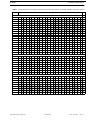
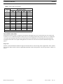
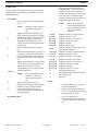
TABLE 2. Address
TIF-2000A
DIP Switch Settings
DIP Switch Settings
Logical
Keypanel
Number
SW4
SW5
SW6
SW7
1
down
up
up
up
2
up
down
up
up
3
down
down
up
up
4
up
up
down
up
5
down
up
down
up
6
up
down
down
up
7
down
down
down
up
8
up
up
up
down
9
down
up
up
down
10
up
down
up
down
NOTE:
Shaded area is for CS9xxx system address only.
Internal DIP Switch (S202)
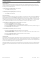
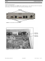
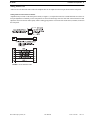
Internal DIP switch (see Figure 3 on page 8) is accessed by removing the top cover. To remove the top cover, remove and
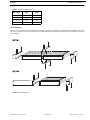
loosen the screws, as indicated in Figure 4. Remove the cover by lifting up on the back portion of the cover. To reinstall the
cover, place the front portion into the grooves on the bottom cover and slide the cover toward the front of the unit while
lowering the back of the cover. Replace and tighten the screws that were removed or loosened as indicated in Figure 4 on
page 11.
Ring Count
Switches 1 and 2 determine the number of rings before the unit answers. Note, the ring count is approximate. These switches
have no effect unless switch 1 on the rear panel DIP switch bank is in the down position. To set the ring count, see Table 3 on
page 12.
Bosch Security Systems, Inc.
User Manual
F.01U.193.286
Rev. 07