1
Installers manual
HMD230 motor drive
English
Version: 1.1 February 2013
Translation of the Original Installers manual
www.heras.com
English
2
www.heras.com
Contents
1
GENERAL .......................................................................................................... 6
1.1
1.2
1.3
1.4
EXPLANATION OF THE SYMBOLS ..................................................................... 6
LISTING OF CHANGES.................................................................................... 6
TERMINOLOGY, DEFINITIONS AND ABBREVIATIONS .......................................... 7
LIST OF ILLUSTRATIONS ................................................................................ 8
2
SAFETY INSTRUCTIONS .................................................................................. 9
3
FUNCTION DESCRIPTION AND CONNECTIONS ............................................... 10
3.1
CONDITIONS ..............................................................................................
3.2
TECHNICAL SPECIFICATIONS .......................................................................
3.3
COMPLETE VIEW OF THE HERAS MOTOR DRIVE ...............................................
3.4
OPERATING MODES: FUNCTIONS AND OPERATION ..........................................
3.4.1
Dead man's operation ............................................................................
3.4.2
Automatic mode ...................................................................................
3.4.3
Emergency operation .............................................................................
3.4.4
Automatically changing operating modes .................................................
3.5
ACCESSORIES THAT CAN BE CONNECTED ......................................................
4
10
10
11
12
12
13
13
14
15
INSTALLATION ............................................................................................... 16
4.1
ASSEMBLING THE MOTOR DRIVE ................................................................... 16
4.2
ELECTRICAL CONNECTION ........................................................................... 17
4.2.1
Connecting the supply voltage and the drive motor ................................... 17
4.2.2
Instructions for EMC installation ............................................................ 18
4.3
CONNECTING THE INPUTS ............................................................................ 18
4.3.1
Power supply for external devices ........................................................... 19
4.3.2
Connecting the controls ......................................................................... 19
4.4
STATIONARY ANTI-CRUSHING SAFETY PROTECTION DEVICES .......................... 20
4.4.1
Connecting the ISK system .................................................................... 20
4.4.2
Connecting a photocell........................................................................... 21
4.4.3
Wiring diagram for the inputs on the terminal block .................................. 22
4.4.4
Incremental encoder ............................................................................. 22
4.5
RELAY OUTPUT CONNECTIONS ...................................................................... 23
4.5.1
Relay output with 24 VDC ........................................................................ 24
4.5.2
Relay output with 230 VDC ...................................................................... 24
4.6
CONNECTING THE RADIO-FREQUENCY RECEIVER ............................................ 25
5
CONTROL UNIT AND DISPLAY READINGS....................................................... 26
5.1
TWIST AND SELECTOR SWITCH .................................................................... 26
5.2
LCD SCREEN ............................................................................................... 26
5.2.1
Display of operating modes .................................................................... 27
5.2.2
Date and time display ............................................................................ 28
5.2.3
LCD sensor display ................................................................................ 28
5.2.4
Selecting the menu system .................................................................... 29
5.3
7-SEGMENT LED DISPLAYS ........................................................................... 29
5.3.1
Displaying operating modes with 7-segment LED displays .......................... 30
English
3
www.heras.com
5.3.2
LED sensor display ................................................................................ 30
5.4
MENU DISPLAY INSTRUCTIONS ..................................................................... 31
5.5
MENU STRUCTURE AND TEXTS THAT ARE DISPLAYED....................................... 32
6
PARAMETER SETTINGS ................................................................................... 36
6.1
GENERAL PROGRAMMING INSTRUCTIONS ...................................................... 36
6.1.1
Navigating the menu ............................................................................. 36
6.2
INSTALLING THE GATE AND MAKING SETTINGS .............................................. 37
6.2.1
Installing the dead man's keys................................................................ 37
6.2.2
Changing the direction of rotation of the drive .......................................... 37
6.2.3
Programming stationary anti-crushing safety protection devices (SKL) ........ 37
6.2.4
Programming the moving anti-crushing safety protection devices (ISK) ....... 38
6.2.5
‘Teaching’ the end positions of the gate ................................................... 38
6.3
FURTHER OPERATING PARAMETERS .............................................................. 39
6.3.1
Setting the language ............................................................................. 39
6.3.2
Changing the operating mode: Dead man's operation / Automatic mode ...... 39
6.3.3
OPEN, CLOSE and STOP controls ............................................................. 39
6.3.4
Toggle impulse key ............................................................................... 40
6.3.5
Installing/Setting a part open function ..................................................... 40
6.3.6
Installing/Setting an emergency stop input .............................................. 40
6.3.7
Setting a photocell ................................................................................ 40
6.3.8
Connecting a flashing light ..................................................................... 41
6.3.9
Setting a lamp (yard lighting) ................................................................. 41
6.3.10 Connecting the status display of a gate .................................................... 42
6.3.11 Programming service intervals ................................................................ 42
6.3.12 Setting an external heating .................................................................... 43
6.3.13 Setting the emergency situation function ................................................. 43
6.3.14 Setting the traffic light ........................................................................... 44
6.4
TIMER-CONTROLLED GATE MOVEMENTS ........................................................ 44
6.4.1
Setting automatic closing (open dwell time) ............................................. 44
6.4.2
Time to close from Part OPEN position ..................................................... 45
6.4.3
Time to close the gate from interim positions ........................................... 45
6.4.4
Setting a short closing time .................................................................... 45
6.4.5
Activating warning time and flashing light ................................................ 45
6.5
SAVING PARAMETERS TO THE MEMORY .......................................................... 46
6.5.1
Saving the parameter settings ................................................................ 46
6.5.2
Restoring parameter settings.................................................................. 46
6.6
SAVING PARAMETERS TO CHIPCARD ............................................................. 46
6.6.1
Saving the parameter settings to card ..................................................... 47
6.6.2
Reading the parameter values from the card ............................................ 47
6.7
SUPPORT DURING DIAGNOSIS ...................................................................... 47
6.7.1
Version display ..................................................................................... 47
6.7.2
Movement commands at start-up ............................................................ 48
6.7.3
Gate status .......................................................................................... 48
6.7.4
Sensor statuses .................................................................................... 49
6.7.5
Temperatures ....................................................................................... 49
6.7.6
Integrated log systems .......................................................................... 50
6.8
REMOTE CONTROL ...................................................................................... 50
6.8.1
Displaying the number of hand transmitters ............................................. 51
English
4
www.heras.com
6.8.2
Teaching hand transmitters .................................................................... 51
6.8.3
Teaching hand transmitter buttons .......................................................... 52
6.8.4
Deleting transmitters from the memory ................................................... 52
6.8.5
Deleting hand transmitter function .......................................................... 52
6.8.6
Deleting all transmitters from the memory ............................................... 53
6.9
INTEGRATED REAL-TIME CLOCK .................................................................... 53
6.9.1
Display date/time .................................................................................. 53
6.9.2
Setting the clock ................................................................................... 53
6.10
CALENDAR FUNCTIONS OF THE MOTOR DRIVE ............................................. 53
6.10.1 Activating the calendar .......................................................................... 54
6.10.2 Displaying the weekly calendar ............................................................... 54
6.10.3 Adding and changing entries in the weekly calendar .................................. 55
6.10.4 Copying a day in the weekly calendar ...................................................... 56
6.10.5 Deleting individual entries ...................................................................... 56
6.10.6 Deleting a week day .............................................................................. 57
6.10.7 Deleting the entire weekly calendar ......................................................... 57
6.10.8 Displaying the yearly calendar ................................................................ 57
6.10.9 Adding and changing entries in the yearly calendar ................................... 58
6.10.10
Copying a day in the yearly calendar .................................................... 59
6.10.11
Deleting individual entries ................................................................... 59
6.10.12
Deleting a day ................................................................................... 60
6.10.13
Deleting the entire yearly calendar ....................................................... 60
6.11
PARAMETER REFERENCE AND/OR FAULT NUMBERS ....................................... 60
8
MAINTENANCE INSTRUCTIONS ...................................................................... 63
9
DECOMMISSIONING AND REMOVAL ............................................................... 63
10
TECHNICAL DATA ........................................................................................ 64
11
APPENDIX A
SPARE PARTS ........................................................................ 65
12
APPENDIX B
ACCESSORIES ....................................................................... 65
13
APPENDIX C
DECLARATION OF CONFORMITY ........................................... 66
English
5
www.heras.com
1
GENERAL
The release of this publication invalidates all prior versions.
The information given in this document is subject to change at any time without notice.
This user manual is aimed specifically at the person who installs and sets up the HMD230
gate motor drive. The motor drive must be commissioned exclusively by accredited, trained
electrical engineers, who are familiar with the safety standards governing the electrical drive
and computerisation technology. The safety regulations must be taken into consideration
absolutely.
This manual demonstrates only a few control functions. You can find information of further
functions, descriptions of special functions and more accurate specifications of the motor
drive in additional descriptions.
1.1
EXPLANATION OF THE SYMBOLS
Caution!:
To prevent personal injury, you must observe the safety instructions
below.
Attention! :
To prevent material damage, you must observe the safety instructions
below.
Information: This is followed by further information or by a reference to other
documents.
1.2
LISTING OF CHANGES
The changes incorporated in this document, the reason of the change in question and the
date of the change are described in the table.
Any material changes as to the contents of this document must be first agreed within the
project management team. This does not apply to formal changes such as spelling errors and
amendments.
The entire document is given a new publication status and is completely redistributed after
every change. Every change to this document must be submitted by the configuration
manager. The configuration manager is responsible for coordination within the project and for
distributing the new release.
Revision
English
Date
1.0
01-05-2012
1.1
02-2013
Description, reason of change
First issue (EF/ER)
Changes to the program version 1.10.10.24
6
www.heras.com
1.3
TERMINOLOGY, DEFINITIONS AND ABBREVIATIONS
AC .............. Alternating Current
FER ............ Fire Emergency Room
B.I.S.T. ....... Built In Self Test
CRC16 ........ 16-bit Cyclic Redundancy Check
DC ............. Direct Current
DIN ............ Deutsches Institut für Normung
EEPROM ...... Electrical Erasable Programmable Read Only Memory
EMC............ Electromagnetic Compatibility
EN .............. European standard
FI ............... Fault Interrupter (residual current circuit breaker)
FU .............. frequency converter
GND ........... ground
HW ............. hardware
IP ............... Intrusion Protection against foreign substances and water
ISK............. inductive cable transfer system supplied by ASO, replacing the
travelling cable for the moving anti-crushing safety protection devices
ISO ............ International Organization for Standardization
LCD ............ Liquid Crystal Display
MMI ............ Man Machine Interface
PWM ........... Pulse width modulation
RAM ........... Random Access Memory
ROM ........... Read Only Memory
RTC ............ real-time clock
SKL ............ anti-crushing safety protection devices
SW ............. software
TÜV ............ Technischer Überwachungsverein, Notified Body
VCC ............ Voltage of Common Collector (operating voltage)
English
7
www.heras.com
1.4
LIST OF ILLUSTRATIONS
Illustration 1: Complete view ............................................................................................................ 11
Illustration 2: Summary of operating modes .................................................................................... 12
Illustration 3: Schedule of options to switch over between operating modes .................................. 14
Illustration 4: Mechanical dimensions .............................................................................................. 16
Illustration 5: Electrical connection................................................................................................... 17
Illustration 6: Connecting external devices ...................................................................................... 18
Illustration 7: Electrical connection of controls ................................................................................. 19
Illustration 8: Electrical connection of anti-crushing safety protection devices and ISK .................. 20
Illustration 9: Electrical connection of a one-way photocell ............................................................. 21
Illustration 10: Electrical connection of a reflective photocell........................................................... 21
Illustration 11: Installation of inputs incl. photocell ........................................................................... 22
Illustration 12: Electrical connection of incremental encoder ........................................................... 22
Illustration 13: Electrical connection of 24 VDC relay ........................................................................ 24
Illustration 14: Electrical connection of 230V relay .......................................................................... 24
Illustration 15: Electrical connection of radio-frequency receiver module........................................ 25
Illustration 16: Twist and selector switch.......................................................................................... 26
Illustration 17: Information on the LCD screen ................................................................................ 26
Illustration 18: Date and time display ............................................................................................... 28
Illustration 19: Display of main menu on the LCD screen ................................................................ 29
Illustration 20: Layout and meanings of 7-segment LED displays ................................................... 29
Illustration 21: Chipcard reader ........................................................................................................ 46
English
8
www.heras.com
2
SAFETY INSTRUCTIONS
•
•
•
•
•
•
•
•
•
•
•
•
•
•
•
•
•
•
Carefully read the User Manual before commissioning the HMD230 gate motor drive.
The motor drive must only be installed and commissioned by trained professionals who
have acquainted themselves with this User Manual and the applicable instructions on work
safety and accident prevention. Always observe and respect the instructions contained in
this manual.
The User Manual must always be available at the location where the motor drive is used.
All staff who operate and maintain the motor drive must read this manual thoroughly and
apply it.
After it has been commissioned, the user of the gate system or its representative must be
given an explanation of how to operate the system.
Only professional electrical engineers are allowed to carry out work on electrical systems!
Always comply with the applicable electro-technical safety instructions, as well as the
safety instructions provided by industrial associations, insurers etc. if relevant.
It is the responsibility of the manufacturer and the user of the system / machine on which
the motor drive is used to coordinate and observe all applicable safety instructions and
rules.
The instructions in this manual must be observed in order to comply with the warranty
conditions as regards operation and safety. Ignoring warnings may lead to physical injury
and material damage. The manufacturer does not accept any liability for damage that is
the consequence of any failure to comply with the instructions.
There are no user-serviceable parts inside the motor drive. Any adjustments and/or
repairs made by the user without the manufacturer's approval will invalidate all warranty
claims and the manufacturer's liability, if any.
Prior to performing connection activities, the drive system must always be disconnected
from the power supply. Make sure that the power supply continues to be interrupted while
the connection activities are being performed.
All pulse generators and control facilities of the gate must be installed such that they are
visible from the gate and at a safe distance from the moving parts of the gate. Observe a
minimum installation height of 1.5 metres.
Do not enable or allow children to play with the gate motor drive.
Before moving the gate, check that there are no people or objects in the danger zone of
the gate.
All available emergency controls must be checked prior to commissioning the system.
Never insert anything in a running gate or in its moving parts.
Be alert to locations at gate systems where limbs may be crushed or which may cause
abrasion injury or damage and make these locations safe.
The motor drive guarantees functional safety, but it does not guarantee the safety of the
entire system. Therefore, prior to using the motor drive, a safety assessment must be
performed for the entire system, according to DIN EN 13241-1 "Gates – product
standard".
The system must be inspected at regular intervals by experts for its proper functioning in
order to ensure that the safety system complies to the DIN EN 12453 standard "Safety in
use of power-operated doors and gates". This inspection must be documented such that it
can be verified.
The HMD230 is a frequency converter. Since dangerous live voltage may still
be present after switching off the HMD230, you must observe a 3 to 5 minute
waiting time to make sure that all power has discharged. Working on a live
frequency converter PCB involves a risk of fatal injury!
If the HMD230 must be fused with a residual current circuit breaker (Fl switch),
only the FI switch type B, that is sensitive to all types of current, may be applied.
English
9
www.heras.com
3
FUNCTION DESCRIPTION AND CONNECTIONS
This document is a description of the HMD230 electrical gate motor drive manufactured by
ASO. It describes how to install, use, maintain, repair, decommission and remove the motor
drive.
The HMD230 is an electronic control unit with safety functions that is intended for use as a
motor drive to operate sliding gates, rolling gates and vertical bar gates, swing and folding
gates and barriers in industrial environments.
The HMD230 is also a frequency converter that can operate a three-phase motor with max.
0.75kW on a 1-phase grid. The frequency converter offers the options of 'soft starting' and
'soft stopping' the gate, as well as several different gate speeds.
3.1
CONDITIONS
The motor drive is only fully functional if installed in a gate system that is ready for use. This
may require extra external components such as:
-
drive
controls
signal elements
sensor elements
(electric motor and transmission)
(switches / buttons)
(flashing lights / horns)
(safety strips / anti-crushing safety protection devices / photocells)
They are not enclosed with the motor drive.
3.2
TECHNICAL SPECIFICATIONS
The HMD230 has the following characteristics:
•
•
•
•
•
•
•
•
•
•
•
•
English
automatic configuration and many pre-programmed features for standard gate systems
an extensive programming system for dedicated inputs: front OPEN, STOP, CLOSE,
TOGGLE
two freely programmable inputs
three dedicated output relays (clearing relays) for flashing light, OPEN position and
CLOSED position
two freely programmable relays (alternating relays)
alternatively, the ISK and SKL can also be connected with M8 connectors and screw
terminals
separate photocell input
7-segment display for status messages
LCD display for diagnosis and for programming via menus
operation and configuration via rotary and selector switches
real-time clock with a spare battery for timed functions and calendar actions
optional radio-frequency remote control receiver
10
www.heras.com
3.3
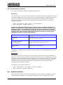
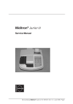
COMPLETE VIEW OF THE HERAS MOTOR DRIVE
Illustration 1: Complete view
Designations of the numbered parts:
1.
2.
3.
4.
5.
6.
7.
8.
9.
10.
11.
12.
13.
14.
15.
16.
17.
18.
English
LCD text display (removable)
7-segment display (under the LCD display)
Serial interface
Input for incremental encoder
Battery for real-time clock
Twist and selector switch for making settings
Communication module slot (optional)
External radio-frequency receiver (optional)
Connection for external antenna
ISK7
ISK connection
SKL connection for both running directions
Fuse for external loads (230V)
Connection for further 230V AC/ 50Hz loads
Motor connection
230V AC/ 50 Hz power supply
Relay outputs
Input connections for safety and operating
11
www.heras.com
3.4
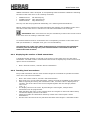
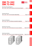
OPERATING MODES: FUNCTIONS AND OPERATION
The control software is divided into separate function modules and is available to users in
three possible operating modes (dead man's operation, automatic mode and emergency
operation):
Illustration 2: Summary of operating modes
3.4.1 Dead man's operation
The gate motor drive can be operated in dead man's mode with limited comfort. In dead
man's mode, the gate can only be moved using the OPEN and CLOSE keys that are connected
to the In8 and In7 inputs specifically for this purpose. In this mode, the gate does not require
anti-crushing safety protection devices. The gate will only move for as long as an OPEN or
CLOSE key is pressed. Dead man's operation is only permitted if the operator can see the gate
system.
If the safety facilities on the gate do not allow automatic operation (e.g. due to a faulty anticrushing safety protection device), the motor drive will automatically switch into this mode
from automatic mode. In this event, and to alert the operator, the gate movement will not
start until after the command key (OPEN or CLOSE) has been pressed for a prolonged time
and after a two-second delay.
When employing dead man’s operation, in addition to the OPEN and CLOSE keys, there is also
a STOP key. If this key is not connected, a wire must be connected from the + 24 volt to the
corresponding input
English
12
www.heras.com
3.4.2 Automatic mode
If the safety facilities have been installed completely, the motor drive will usually work in the
automatic mode. The user can only use all motor drive functions in automatic mode. Total
safety of the gate is guaranteed here by the activated safety facilities.
Opening or closing the gate can be initiated in automatic mode by:
a command key (OPEN, CLOSE, PARTIALLY OPEN)
an impulse key with toggle function (OPEN, STOP, CLOSE, STOP)
OPEN, CLOSE, STOP commands via the remote control
Every movement command causes the full action that has been selected to be performed
(open gate, close gate etc.). Every action is stopped immediately by a stop command or a
signal from the safety facilities.
Activating the anti-crushing safety protection devices causes the gate to immediately move in
the opposite direction. If a photocell is interrupted while the gate is closing, this will cause the
gate to be opened as far as the point where the closing movement started (OPEN or PARTLY
OPEN).
A movement command for the opposite direction will gradually decelerate the gate and then
cause it to move in opposite direction.
Automatic mode if the gate has not installed fully yet:
If the gate has not been fully installed yet, or if motor drive programming has not
been completed (e.g.: the end positions of the gate have not been defined yet), the motor
drive will work in a special safety mode.
The gate will then only run at dead man's mode speed. Only after the end positions for the
OPEN and CLOSED positions have been set and after a measuring run at dead man's mode
speed has been performed, will the system switch over to the automatic mode speed.
If the power supply to the drive has been interrupted, the gate will also only run at dead
man's mode speed until the first time when an end position has been reached.
3.4.3 Emergency operation
The gate motor drive can switch over automatically from automatic mode to emergency
operation. This automatic switch-over can only take place after a "Function emergency
situation" input signal which is generated by a fire emergency room. Only the one movement
(OPEN or CLOSE, depending on programming) that is requested will be performed at dead
man's mode speed in this operating mode. The safety facilities are also activated during this
movement. The movement can be interrupted by pressing and holding the STOP key or by a
safety device being triggered. When this interruption no longer applies, the gate will
immediately continue to move. At the end of the emergency movement and after the signal
("Function emergency situation") has been reset, the software of the motor drive will initiate
a restart to enable safe switch-over to automatic mode.
Any static active OPEN or PARTLY OPEN signals are ignored by the motor drive in this
operating mode.
English
13
www.heras.com
Just as the command triggered by an OPEN or CLOSE command key being pressed cannot be
performed when a program is started, a static active "Emergency situation" input signal will
also not be carried out when switching on the motor drive.
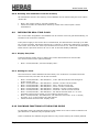
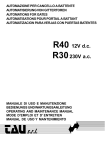
3.4.4 Automatically changing operating modes
The gate motor drive can switch over from automatic mode to emergency operation if it has
been programmed to allow this and the HMD230 recognises a corresponding "emergency
situation" signal from a fire emergency room. This operating mode will then be performed
until the motor drive is restarted. The restart will take place automatically when the
"emergency situation" signal is reset (is no longer active) and the required gate position
(OPEN or CLOSED) has been reached. Restarting causes the motor drive to resume
automatic operation and wait for the first movement command.
If electronic safety facilities on the gate are out of operation (e.g. a faulty photocell), the
motor drive can automatically switch over from automatic mode to dead man's operation.
This automatic switch-over will take place only for the individual motor movement that has
been started and only if the key provided for dead man's operation is pressed. After this, the
motor drive will switch over to automatic mode again, but if a new fault occurs or if the fault
is not remedied, the system can switch over to dead man's operation again for the next
movement.
Changing between operating
Automatic mode
Dead man's mode
Automatic mode
Emergency operation
modes is possible in the following directions:
Dead man's operation mode
Automatic mode (if safety’s have been restored)
Emergency operation
Automatic mode (if no emergency situation signal is
active anymore and after restarting the control
software)
Illustration 3: Schedule of options to switch over between operating modes
English
14
www.heras.com
3.5
ACCESSORIES THAT CAN BE CONNECTED
The HMD230 gate motor drive can be combined with one or several of the components listed
below:
Anti-crushing safety protection devices
Anti-crushing safety protection devices with an 8.2 kOhm terminating resistance for the
opening and closing directions can be connected directly to the HMD230 using M8 connectors
or terminals.
ISK system
The HMD230 has already been fitted with the drive and analysis logic for the ISK inductive
safety system to monitor the moving anti-crushing safety protection devices. The ISK7 is
connected to the HMD230 for this purpose. The stationary SPK55 core can also be connected
directly via an M8 connector or a terminal.
Photocells
One-way photocells or reflective photocells can be connected to a separate input.
Incremental encoder
The incremental encoder of the drive motor, detecting the running direction and the speed of
the motor drive motor can be connected via a four-pole M8 connector.
Radio-frequency receiver
The HMD230 can be fitted with a FM radio-frequency receiver for hand transmitters. The
receiver operates on 868-MHz. An externally installed antenna can be connected to this
receiver.
English
15
www.heras.com
4
INSTALLATION
This chapter is about commissioning the HMD230.
4.1
ASSEMBLING THE MOTOR DRIVE
Attention!
Check the motor drive for possible damage, including transport damage, prior to
assembly.
Do not touch any electronic parts, in particular processor circuit components. Electronic
parts and components may be damaged or become faulty due to electrostatic discharge.
Switch off the power supply to the system before installing the motor drive.
The motor drive must be installed such that it is free from mechanical strain.
Cable entries that are not used must be replaced by closed stepped nipples to ensure that
the housing is safe.
The cables must be free from mechanical pull strain.
If the motor drive is mounted on a conducting surface it must be connected to an
effective ground on the PE. The cooling body of the motor drive does not have such a
connection.
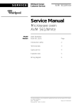
The motor drive is installed using fillister head screws with a diameter of 4 mm. The motor
drive is intended for vertical installation.
Illustration 4: Mechanical dimensions
Tip: As the cooling body of the HMD230 heats up during operation, you must pay attention
that the thermal coupling of the cooling body is sufficient. Ideally there is a perfectly fitting
connection between the cooling body and a metal surface which dissipates the heat.
Insufficient heat dissipation may affect the functioning of the motor drive.
English
16
www.heras.com
Never mount the motor drive on a flammable surface such as wood. When mounted on
surfaces that do not efficiently dissipate heat, the motor drive must be mounted on distance
pieces. If this is done, a convection gap of at least 10 cm must be left above and below.
In continuous operation the cooling body may become as hot as 65 °C.
Note: at higher temperatures the frequency converter will no longer be driven.
4.2
ELECTRICAL CONNECTION
Caution! In principle, and for safety reasons, the electrical system must be connected
by a qualified electrical engineer. Work on the motor drive is only permitted if the
power supply is fully interrupted. To fully interrupt the power supply, an isolator
switch or mains plug must be installed and used. The isolator switch or mains plug must be
within easy reach.
Observe the instructions in the chapter on Safety instructions. Avoid parallel signal and energy
leads and cables where possible. The dimensions of all leads and cables must be adjusted to
the power consumption.
The stepped nipples used in the housing must only be opened so far that the protection
against water and foreign objects penetrating is still compliant with the IP classification after
introducing the leads and cables.
And damaged stepped nipples must immediately be replaced by undamaged nipples.
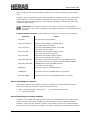
4.2.1 Connecting the supply voltage and the drive motor
When connecting the motors, follow the wiring diagrams as supplied by the motor
manufacturer.
The HMD230 has been designed for 230VAC single-phase input voltage:
it generates a rotary field of 3 x 230VAC.
Connect the motor drive as shown in the illustrations below:
Illustration 5: Electrical connection
Make sure that the earth lead and the motor connection cable shield are connected correctly.
While commissioning, check the direction of rotation of the motor, so that the gate will move
in the required direction when the OPEN key is pressed. If necessary, switch connections V
and W or change the direction of rotation by means of the configuration in the menu.
English
17
www.heras.com
4.2.2 Instructions for EMC installation
Attention: If the installation does not comply with EMC requirements, other
equipment in the direct vicinity of the motor drive may be disturbed.
The HMD230 is a motor drive which includes a frequency converter. The switching technology
inherent in frequency converters may lead to disturbances in their direct vicinity.
A shielded cable must always be used for the motor cable. Connect the shield to the motor
using an EMC screw connection and connect it in the motor drive using the PE terminal
provided for this purpose.
If the system has to comply with the requirements of EN 61000-6-3, the power supply lead
and all control leads must have ferrite cores.
4.3
CONNECTING THE INPUTS
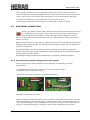
The HMD230 has two terminal blocks next to each other for connecting external devices. The
left-hand block is intended for outputs, whereas controls or sensors can be connected to the
right-hand block.
Illustration 6: Connecting external devices
The inputs of the HMD230 have the following input functions.
English
IN1
Open
IN2
Stop
In3
Close
In4
Toggle
In5
Freely programmable
In6
Freely programmable
In7
Close in dead man's operation
In8
Open in dead man's operation
18
www.heras.com
After entering a password, the service engineer can connect the following functions to the
inputs In5 and In6:
Part open
Emergency stop
Emergency
4.3.1 Power supply for external devices
To supply power to the external sensors and controls, the HMD230 features a 24 VDC power
supply with potential separation and voltage stabilisation which can supply a maximum
current of 500 mA. The supply voltage is fused with an automatically resetting fuse on the
PCB. A separate 24V ¯|_|¯ power supply output is available for the emergency stop and
emergency situation functions. The supply voltage of the motor drive is switched on and off in
a controlled manner on this power supply output during rest phases. This enables the motor
drive to identify the safe operation of the controls on its inputs.
External loads of 230VAC can be connected to a fused power output on the HMD230 PCB
(Illustration 1: Complete
view; pos. 14 in the illustration).
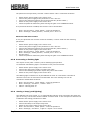
4.3.2 Connecting the controls
The controls (keys) for the open, close, toggle and part open functions are connected through
a make contact. Switches with a static make contact (e.g. timer) are also allowed for the
open and part open functions.
Only controls with a break contact are used for the stop, emergency stop and emergency
situation functions.
ATTENTION: The power supply to the controls must go through the synchronised
24V ¯|_|¯ output for the emergency stop and emergency situation functions.
Several break contacts can be switched in series in the form of a stop chain for the stop and
emergency stop inputs.
To comply with the special requirements set on dead man's operation, an OPEN key is always
configured on input In8 and a CLOSED key on input In7. These settings cannot be changed
while programming.
ZU
STOPP
AUF
24V LB In8 In7 In6 In5 In4 In3 In2 In1
in
24V
0V
SKL
open
ISK
SKL
close
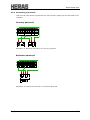
Illustration 7: Electrical connection of controls
English
19
www.heras.com
4.4
STATIONARY ANTI-CRUSHING SAFETY PROTECTION DEVICES
The stationary anti-crushing safety protection devices can be connected directly to the buses
marked "open" and "close" on the PCB, using M8 connectors. If relevant, the anti-crushing
safety protection devices can also be connected to the plug-in terminals in the lower righthand corner of the input terminal block.
Illustration 8: Electrical connection of anti-crushing safety protection devices and ISK
Attention: A single input (SKL open; SKL close) may only be used to connect the M8
connector or the input terminal, but they cannot both be connected to the same input
terminal. This would result in a parallel connection of the anti-crushing safety
protection device, leading to failures.
4.4.1 Connecting the ISK system
The ASO ISK system has already been integrated with the HMD230. A stationary SPK55 core
can be connected to the lower of three 3-pole M8 buses. If relevant, the core can also be
connected to the plug-in terminal in the upper right-hand corner of the input terminal block.
Attention: Connecting the M8 connector and the input terminal to one and the same
input at the same time is not allowed here either. This would result in a parallel
connection of the anti-crushing safety protection device, leading to failures.
English
20
www.heras.com
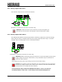
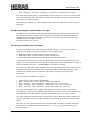
4.4.2 Connecting a photocell
Both one-way and reflective photocells of a 24V operating voltage can be connected to the
HMD230.
One-way photocell:
24V LB In8 In7 In6 In5 In4 In3 In2 In1
in
24V
0V
SKL
open
ISK
SKL
close
Illustration 9: Electrical connection of a one-way photocell
Reflective photocell:
24V LB In8 In7 In6 In5 In4 In3 In2 In1
in
24V
0V
SKL
open
ISK
SKL
close
24V
Illustration 10: Electrical connection of a reflective photocell
English
21
www.heras.com
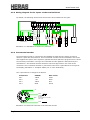
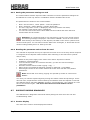
4.4.3 Wiring diagram for the inputs on the terminal block
By default, the following sensors and controls have been installed on the gate:
SKL
open
8k2
Lichtschranke
SKL
close
SKL close
0V
ISK
8k2
0V
SKL open
0V
ISK
AUF
0V
In1
In2
In3
STOPP
24V
In4
ZU
24V
In5
In6
Totmann - ZU
24V
Totmann - AUF
24V
In7
In8
TOGGLE
LB
in
24V
Illustration 11: Installation of inputs incl. photocell
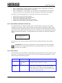
4.4.4 Incremental encoder
An incremental encoder is connected to the HMD230 to determine the gate's movement
direction, speed and end positions. This incremental encoder has been installed in the motor
and supplies two square-wave signals in opposite directions which the program uses to derive
the necessary information. The type of incremental encoder applied is determined by the
manufacturer. Incremental encoders that have not been approved for use must not be
connected. The incremental encoder is connected to the lower 4-pole M8 bus to the right of
the display (Illustration 1: Complete
view: pos. 4 in the illustration).
The 4-pole M8 bus is configured as follows:
Connection
SIGNAL
Wire colour
Pin 1
TSIG2
white
Pin 2
+5V
black
Pin 3
TSIG1
blue
Pin 4
GND
brown
+ 5V
TSIG1
3
2
GND
1
4
Tachosignale
90 Grad
gegeneinander verschoben
TTL-Pegel
TSIG2
Illustration 12: Electrical connection of incremental encoder
English
22
www.heras.com
Attention: If the gate is disengaged from the motor drive and moved to another
position by hand, the closed position of the gate must be redefined in the program
before using the motor drive again.
4.5
RELAY OUTPUT CONNECTIONS
The HMD230 has five relays available for signalling and lighting purposes (see illustration 6).
Relays Rel1 to Rel3 are make contacts, the other two relays (Rel4, Rel5) are make-and-break
contacts. The switch contacts are potential free and are capable of ohmic loads of up to
250 W.
A fused 230V output is available to connect AC loads to the power supply of the HMD230
(Illustration 1: Complete
view: pos. 14 in the illustration). The wiring from this output to the
relevant relay must be installed by a professional.
The following functions have already been set on the relays:
Rel1
Flashing light
Rel2
Gate OPEN status display
Rel3
Gate CLOSED status display
Rel4
Freely programmable
Rel5
Freely programmable
The output of Rel1 is switched on at the start of the warning time and permanently during the
movement. The flashing function must be performed by the connected lamp.
The service engineer can assign one of the following functions to the relays Rel4 and Rel5:
Lighting (yard lighting) with deactivation relay after a gate movement has ended
Traffic light function red/green
Maintenance signal (maintenance necessary)
Extra electrical heating in case of frost
Attention: When assigning functions to individual relays make sure not to configure
any outputs twice.
English
23
www.heras.com
4.5.1 Relay output with 24 VDC
24V indicator lamps can be connected as follows:
Rel4
24V LB In8 In7 In6 In5
in
Rel4
Rel1
Rel2
Rel3
24V
0V
24V
Blinklicht
Tor offen
Tor zu
Illustration 13: Electrical connection of 24 VDC relay
Attention: Take the motor drive's maximum current load capacity of
500 mA into account when connecting the external 24V power supply.
4.5.2 Relay output with 230 VDC
The HMD230 PCB features a 230V output which is fused by a glass fuse (6.3A slow-acting).
230V loads can also be switched with this power supply output and the relays. A relevant
indicator lamp or flashing light can be connected as follows:
N
PE
L
Rel4
N
PE
Rel4
L1'
Rel1
Rel2
Rel3
Illustration 14: Electrical connection of 230V relay
Attention: When connecting, take the maximum current load capacity of the power
supply output into account. Furthermore, every individual relay is restricted to a
maximum load of 250 W.
Only replace the fuse (6.3A, slow-acting) by a fuse of the same rating.
Caution: In accordance with the standards, the relay outputs have been separated
from the low safety voltage on the motor drive. However, since the individual relay
connections do not comply with this condition,
Connecting the relays inside the HMD230 with 230 VAC and is not allowed.
Combining 230 VAC and 24 VDC on the relays of the external backplane is.
English
24
www.heras.com
4.6
CONNECTING THE RADIO-FREQUENCY RECEIVER
The HMD230 can optionally be fitted with a radio-frequency receiver for hand transmitters.
The radio-frequency receiver works with 868 MHz and FM modulation. The radio-frequency
receiver is factory-fitted to the right of the slot for the communication interface on the bus
terminal strip.
The receiver can also be retrofitted or replaced.
This receiver can also be combined with an external antenna
to be connected to the plug-in terminal directly under the module.
The internal core of the coax cable of the antenna is
connected to the right-hand terminal, near the housing
side. The antenna shield is connected to the left-hand
terminal.
Illustration 15: Electrical connection of radio-frequency receiver module
Information:
Only hand transmitters whose use has been approved by the manufacture can
be ‘taught’ (programmed automatically) to the motor drive.
English
25
www.heras.com
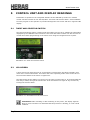
5
CONTROL UNIT AND DISPLAY READINGS
Information is inputted in the integrated software of the HMD230 by means of a modern
control unit that consists of one switch/button: the twist and selector switch. Visual feedback
from the program to the operator is provided through the LCD screen and the 7-segment LED
display.
5.1
TWIST AND SELECTOR SWITCH
The twist and selector switch, located under the battery for the clock, enables the information
displayed by the HMD230 to be influenced. This twist and selector switch can also be used to
control the manual programming of the motor drive using the integrated menu system.
Illustration 16: Twist and selector switch
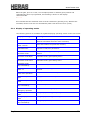
5.2
LCD SCREEN
A loose LCD screen with two lines of 16 characters each has been provided to display more
motor drive control information. This shows the active operating mode of the motor drive or
the movement status of the motor in legible text.
The background of the display is lit for as long as input is entered into it. 20 seconds after the
last entry is made, the light is switched off. It can be switched on again at any moment by
turning the selector switch.
Illustration 17: Information on the LCD screen
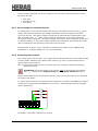
Information: After resetting or after switching on the power, the display light will
blink for a few seconds. This indicates that the processor is booting; it is not a fault
condition.
English
26
www.heras.com
When the gate, prior to a reset, is in the Open position or Partially open position and
“automatically close” is programmed, the following is shown on the display:
“Auto.Close ON”
“-------“
This indicates that the automatic timer must be restarted by pressing a key. Without this
command, the drive will not run automatically after it has been turned on (reset).
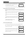
5.2.1 Display of operating modes
The following options are available as regards displaying operating modes on the LCD screen:
Display reading
English
Meaning
HMD230 Pe:x.xx
Start indication of the periphery controller
(wait for information from the motor controller)
Init/ClearEEPROM
WAIT: 120 sec.
Clear and initialize the parameter memory
Load Parameter
Request to load/save parameters
Heras HMD230
Automatic mode
Automatic operating mode, the gate is now in the idle
position
Automatic mode Open
Automatic mode; gate opening active
Automatic mode Close
Automatic mode; gate closing active
Automatic mode
Stop immediately
Automatic mode; STOP active
Automatic mode
Close: xx
Automatic mode; the gate closes automatically after XX
seconds
Heras HMD230
Dead man's operation
Idle position for dead man's operation
Dead man's operation
Open
Open gate in dead man's operation mode active
Dead man's operation
Close
Close gate in dead man's operation mode active
Dead man's operation
Stop immediately
Dead man's operation STOP active
Heras HMD230
Emergency operation
Idle position for emergency operation
Emergency operation
Open
Emergency operation; gate opening active
Emergency operation
Close
Emergency operation; gate closing active
Emergency operation
Stop immediately
Emergency operation; STOP active
27
www.heras.com
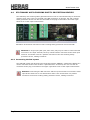
5.2.2 Date and time display
You can permanently display the current time on the screen of the operating mode display by
briefly pressing the twist and selector switch once. The clock date is shown in the top line,
using the "year.month.day" format. The lower line shows the time in the 24-hour
"hours:minutes:seconds" format. The selected operating mode is shown again 20 seconds
after operating the twist switch.
Illustration 18: Date and time display
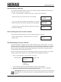
5.2.3 LCD sensor display
The display also provides detailed information on the sensors that have been configured.
Pressing the twist and selector switch again displays the current state of the sensors that
have been set. Turning the switch displays the individual sensors one by one. The sensor
from the parameter list is always listed in the first line. The second line shows the current
sensor state. Here a "1" stands for an active sensor and a "0" for an inactive sensor. This
information is constantly updated to facilitate trouble-shooting. Again, the operating mode is
shown again 20 seconds after operating the twist switch.
English
Display reading
Meaning
No sensors
set
Is shown if no sensors have been programmed
Sensors Begin
Turn the selector switch in a counter-clockwise direction to
access the first entry in the sensor table
Pulse generator
value: xxxxxxxxxx
Current value of the incremental encoder
Stat.prot. OPEN
Value: 1 => x
Stationary anti-crushing safety protection device for the
OPEN direction of the gate
Stat.prot. CLOSE
Value: 1 => x
Stationary anti-crushing safety protection device for the
CLOSING direction of the gate
Mov.prot. OPEN
Value: 1 => x
Moving anti-crushing safety protection device for the OPEN
direction (ISK)
Mov.prot. CLOSED
Value: 1 => x
Moving anti-crushing safety protection device for the
CLOSING direction (ISK)
Vehicle prot.
Value: 1 => x
Photocell status
Loop detector A
Value: 0 => x
Status of traffic loop A
Loop detector B
Value: 0 => x
Status of traffic loop B
Sensors End
Turn the selector switch in a clockwise direction to access
the last entry in the sensor table
28
www.heras.com
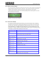
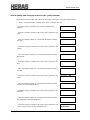
5.2.4 Selecting the menu system
The HMD230 menu system is accessed by pressing the twist and selector switch for approx. 2
seconds while the operating mode is displayed. The display then shows the text "Main menu".
Illustration 19: Display of main menu on the LCD screen
Turn the selector switch to select the individual menu options and then press the switch to
activate the selected option. The first menu option in a menu level always brings you back
one level. The "Exit main menu" option in the main menu closes the menu display and
restarts the control software.
5.3
7-SEGMENT LED DISPLAYS
The basic PCB of the HMD230 has two 7-segment LED displays next to each other. They are
used to display the operating mode or the state of the connected sensors.
You can switch between the operating mode and sensor display modes by briefly pressing
the twist and selector switch.
a
f
a
b
f
g
g
c
e
d
b
e
c
d
Illustration 20: Layout and meanings of 7-segment LED displays
English
29
www.heras.com
5.3.1 Displaying operating modes with 7-segment LED displays
The following options are possible in the operating mode display:
Display reading
Meaning
-.-
Start indication of the peripheral controller
(wait for synchronisation between the controllers)
oo
Clear and initialize the parameter memory
Ld
Request to load/save parameters
Au
Idle position in automatic mode
dE
Idle position for dead man's operation
Ey
Idle position for emergency operation
OP
Gate opening active
CL
Gate closing active
pc.
STOP active
99 - 1
Seconds - count down when an automatic closing movement
is active
5.3.2 LED sensor display
The individual LED segments display the possibly connected anti-crushing safety protection
devices and photocells in sensor display mode (briefly press the twist and selector switch).
The allocation of the segments to the connected input sensors is shown in the list below:
Left-hand display
Segment a:
Segment f:
Segment e:
PHOTOCELL
SKL for "Closing" direction
ISK for "Closing" direction
Right-hand display
Segment a:
PHOTOCELL
Segment b:
SKL for "Opening" direction
Segment c:
ISK for "Opening" direction
The relevant segment lights up if the sensor input that has been assigned to it is not active.
The relevant segment is switched off when the sensor is activated.
The following is displayed if all sensors are connected and have not been
activated:
English
30
www.heras.com
5.4
MENU DISPLAY INSTRUCTIONS
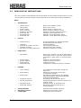
The menu system of the HMD230 can only be called up if the display has been fitted. You can
use the twist and selector switch to select submenus. This offers the following possibilities:
Menu:
1.
Identification:
2.
3.
4.
5.
6.
7.
English
Master version:
Gate profile:
Serial number
Motor controller:
Periphery controller:
Parameter Set
Bootloader Mot
Bootloader Per
Motor drive software version
Motor drive version
Serial number of motor drive
Motor controller software version
Periphery controller software version
Software version parameter set
Software version Bootloader motor
Software version Bootloader periphery
Service:
•
Password entry:
•
•
•
•
Language:
Direction of rotation of motor:
Calendar selection:
Emergency current parameters:
Access (password) for authorised people
and activating extra functions.
Language settings
Anti-clockwise/clockwise
Activate week/year calendar
Setting for emergency current
Diagnostics:
Gate status:
Sensor status:
System logbook
Event logbook
Measured Temp
Motor drive condition, as well as maintenance
information (errors / input and output states /
temperature / gate cycles / movement times,
etc.).
Status of connected sensors
Logbook of all occurrences
Logbook of events
Temperature of CPU & Frequency controller
Settings:
Timer settings:
End positions:
Assign input:
Protection devices:
Special parameters:
Operating mode:
Parameter backup:
Clock/Calendar:
RF remote control:
Traffic light:
Time settings for automatic closing and
light timer.
Setting the end position of the gate
(incremental encoder).
Activation for flashing light, yard lighting,
gate status display, extra electrical brake,
maintenance designation.
Activating vehicle protection device
Setting parameters for service intervals and
heating output
Setting the type of operating mode
Saving and restoring settings (e.g.
factory settings)
Date/Time and calendar functions.
Settings for the remote control
Traffic light control functions
31
www.heras.com
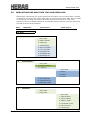
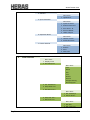
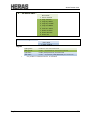
5.5
MENU STRUCTURE AND TEXTS THAT ARE DISPLAYED
Selecting the menu brings you to the main menu level where you can choose from a number
of submenus. The first menu option "Exit" lets you exit the menu system after which a restart
or reset brings you back in the active operating mode of the motor drive. How many
submenu levels are available depends on the password that is entered. First-level submenus
can lead to second-level submenus.
Menu
Mainmenu
Menu level 1
Menu level 2
Quit Menu
1 Identification
Menu back
1 Master Version
2 Gate type
3 Serialnumber
4 Motor Controller
5 Peri. Controller
6 Parameter Set
7 Bootloader Mot
8 Bootloader Per
2
Service Menu
Menu back
1 Password Input
2 Language
Menu back
1 Dutch
2 English
3 French
3 Mot. Rotations
4 Calendar Choice
5 Emergency Para
3
Diagnosis
Menu back
1 Gate State
Menu back
1 Gate Situation
2 Input: 876543
3 Output: 54321
4 Completed Cycles
5 Motor runtime
6 Last Service
English
32
www.heras.com
7 RESET Service
2 Sensor state
Start of sensors
LimitSwitch OPEN
LimitSwitch. DICHT
Part Open Switch
Incr. Encoder
Stat. Edge OPEN
Stat. Edge DICHT
Mov. Edge OPEN
Mov. Edge DICHT
Lightbarriert
Loopdetector A
Loopdetector B
End of sensors
3 System Logbook
4 Event Logbook
5 Measured Temp.
Menu back
1 CPU Temperature
2 FR Temperature
3 Reset Min./Max.
4
Instellingen
Menu back
1 Set Timer
Menu back
1 Lighting (s)
2 TMR keep open
3 TMR keep part op
4 TMR Autom. Close
5 Secundary Time
6 Light Output
7 Flashlight Premon
2 Gatelimits
Menu back
1 Set Close Limit
2 Set Part Open
3 Set Open Limit
4 RESET Positions
3 Assign Inputs
Menu back
1 Partial Open
2 Emergency stop
3 EMERGENCY (CIE)
English
33
www.heras.com
4 Safeties
Menu back
1 Lightbarrier
5 Spec.Parameter
Menu back
1 Cycles To Servi
2 RuntimeToService
3 Serv.Interv. M
4 Service Output
5 Heater Output
6 Operation Mode
Menu back
1 Hold to run Mo
2 Automatic Mode
7 Param. Backup
Menu back
1 Restore
2 Save
3 Writ Card
5
Clock/Calendar
Menu back
1 Display Clock
2 Set Date/Time
Menu back
Year
Month
Day
Hour
Minute
Second
Daylight Saving
Now daylight?
3 Cal. Activation*
4 Disp.Week Cal.*
5 Edit Week Cal.*
Menu back
1 Set weekdays*
2 Delete Week*
6 Disp.Year Cal.*
7 Edit Year Cal.*
Menu back
1 Set day*
2 Del. Year Cal.*
English
34
www.heras.com
6
RF Remote CRTL.
Menu back
1 Active Transmi
2 Prog. transmi
3 Prog.Key OPEN
4 Prog.Key CLOSE
5 Prog.Part.OPEN
6 Prog.Key TOGG
7 Delete Transmi
8 Delete PlaceNo
9 Delete All
7
Traffic Light
Menu back
1 Outp.TrafficLi
Legend:
*
English
light green:
visible for user and technician
dark green:
visible + adjustable for user and technician
light blue:
visible (with password) for technician
dark blue:
visible + adjustable (with password) for technician
only visible if "Calendar Choice" is activated
35
www.heras.com
6
Parameter settings
6.1
GENERAL PROGRAMMING INSTRUCTIONS
Many control functions of the HMD230 are achieved through parameters that are stored in
the device and that can be changed. These parameters are loaded into the motor drive during
the manufacturing process and they provide the specific behaviour of a defined gate. The
user or installer of the gate motor drive can access many of these parameters via the menu
system.
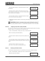
6.1.1 Navigating the menu
How to select menu options and how to navigate for entering the password are demonstrated
here, starting from the operating modes display. The display initially shows "Automatic mode"
and after the twist and selector switch is pressed for two seconds and released again the
menu display changes. The following will then be displayed:
Main menu
1 Identification
Turning the selector one position further in a clockwise direction displays the following
information:
Main menu
2 Service Menu
Press the selector switch to activate this menu option and go down one level in the service
menu:
Service Menu
1 Enter passw.
Press the switch to activate this menu option and to access the field where you can enter the
password:
Enter passw.
Value: 33333
Turn the switch to change the preset value shown. The faster you turn, the faster the values
will change. Press the switch to store the value that you have set and to display the previous
menu option again:
Service Menu
1 Enter passw.
If the password has been entered correctly, you can immediately select the passwordprotected menu options and entry possibilities. The password will be valid for 10 minutes and
will then be reset automatically to the value 33333 if no further entry is made.
English
36
www.heras.com
By pressing and holding the selector switches for two seconds, you can immediately select
the main menu option "Exit main menu":
Main menu
Exit Menu
When this menu option is selected, the motor drive will restart the program (reset) and the
active operating mode will be switched on again (here: "Automatic mode").
6.2
INSTALLING THE GATE AND MAKING SETTINGS
Before commissioning the HMD230 and making the gate settings, several things have to be
installed and set first.
6.2.1
Installing the dead man's keys
You cannot put a gate into operation until at least one OPEN and one CLOSED key have been
connected for dead man's operation. Since you cannot set the end positions without these
keys, you have to perform the following actions in the sequence described below.
6.2.2
Switch off the power supply to the motor drive.
Connect the keys to the 24V power supply.
Connect the key for OPEN [dead man's key] to input terminal In8 (make contact ).
Connect the key for CLOSED [dead man's key] to input terminal In7 (make contact ).
Switch on the power supply of the motor drive.
Check that the keys work.
Changing the direction of rotation of the drive
If, when using the motor for the first time, you find that the gate is moving in the wrong
direction, you can reverse the direction of rotation of the motor by switching the two phases
of the motor connection. However, you can also change the direction of rotation by changing
a software setting. Proceed as follows to make the relevant change:
Menu: "Service Menu", "Enter passw.": enter the password.
Menu: "Service Menu", "Motor dir.of rot.": change the value to "1".
Double-check that the gate moves in the right direction!
6.2.3 Programming stationary anti-crushing safety protection devices (SKL)
The stationary anti-crushing safety protection devices (SKL) are always delivered preactivated.
English
Switch off the power supply to the motor drive.
Connect the anti-crushing safety protection device(s) for the OPEN direction to the SKL
open connection.
Connect the anti-crushing safety protection device(s) for the CLOSING direction to the
SKL close connection.
Switch on the power supply of the motor drive.
Check that the safety protection devices have been connected correctly and check the
reaction of the gate in the relevant movement direction in automatic mode!
37
www.heras.com
6.2.4 Programming the moving anti-crushing safety protection devices (ISK)
The moving anti-crushing safety protection devices, connected via the ISK, are always
delivered pre-activated.
Switch off the power supply to the motor drive.
Connect the ISK system to the ISK connection.
Switch on the power supply of the motor drive.
Check that the safety protection devices have been connected correctly and check the
reaction of the gate in the relevant movement direction in automatic mode.
6.2.5 ‘Teaching’ the end positions of the gate
The motors of the Heras drive have an incremental encoder module. No further limit switches
are required on the gate. When installing and setting the gate and the drive, the end
positions of the gate are laid down as follows:
Switch off the power supply to the motor drive.
Connect the incremental encoder to the 4-pole bus.
Connect the OPEN key [dead man's key] to input terminal In8 (make contact ).
Connect the CLOSE key [dead man's key] to input terminal In7 (make contact ).
Switch on the power supply of the motor drive.
Menu: "Service Menu", "Enter passw.": enter the password.
Move the gate into the CLOSED position.
Press "Settings", "End positions", "Set CLOSED pos.". The motor drive performs a reset.
Use the dead man's keys to move the gate to its part open position.
Press "Settings", "End positions", "Set part OPEN". The motor drive performs a reset.
Use the dead man's keys to move the gate to its open position.
Press "Settings", "End positions", "Set OPEN pos.". The motor drive performs a reset.
Press the CLOSED button. The motor drive determines the maximum motor running time
and saves it.
A reference run is now performed to lay down the maximum motor running times for moving
from one end position to the other end position. The reference run consists of the gate
moving automatically all the way from the OPEN position to the CLOSED position at low speed
once. The motor drive measures the time that elapses during this reference run and save this
time to its memory. The motor drive is ready for use now.
Check that both end positions are reached and that the motor stops when these end
positions have been reached.
If values have been ‘taught’ incorrectly, all values can be cleared at once by selecting
"Settings", "End positions", "RESET pos.". The total teaching procedure has to be
repeated then.
Attention: Teaching the end positions must always start by teaching the CLOSED
position. Other entry sequences will not be accepted.
Attention: If the gate has been disconnected from the motor drive control system
and has been moved by hand, the gate position will no longer be defined in the
software. You must then manually move the gate to its CLOSED position and set the
position again.
Attention: If there is a power failure while the gate is being moved, it may no longer be
possible to save the gate position. This is indicated by the fact that the gate can no longer be
moved in automatic mode. You must then also manually move the gate to its CLOSED
position and set the position again.
English
38
www.heras.com
Procedure:
Move the gate into the CLOSED position.
Press "Settings", "End positions", "Set CLOSED pos.". The motor drive performs a reset.
Check that both end positions are reached and that the motor stops when these end
positions have been reached.
Alternatively:
Press the “OPEN” and “CLOSE” buttons on the backplane simultaneously for more than 8
seconds. The current position of the gate is now the (new) CLOSED position.
6.3
FURTHER OPERATING PARAMETERS
The settings from chapter 6.2 ensure that the gate can be used safely. Many more
installations and motor drive configurations are possible. All configurations and display
options that are only accessible to trained engineers are password-protected.
6.3.1 Setting the language
After entering the password, the engineer can change the menu interface language. Three
different languages can be chosen.
Menu: "Service Menu", "Enter passw.": enter the password.
Menu: "Service Menu", "Language": select the language.
The display uses the new selected language as soon as a new language has been
selected.
6.3.2 Changing the operating mode: Dead man's operation / Automatic mode
The technician can deliberately switch the motor drive, which as a rule works in automatic
mode, to dead man's operation so that the gate can only be driven at a low speed, using the
connected dead man's keys. All safety facilities are deactivated then.
6.3.3
Menu: "Service Menu", "Enter passw.": enter the password.
Menu: "Settings", "Operating mode": select the operating mode.
Check the operation.
OPEN, CLOSE and STOP controls
OPEN, CLOSE and STOP keys can be connected to drive the gate by hand. The inputs referred
to below have already been factory-configured for the relevant functions and do not require
any further settings to be made.
Proceed as follows to connect the keys:
English
Switch off the power supply to the motor drive.
Connect the keys to the 24V power supply.
Connect the OPEN key to input terminal In1 (make contact).
Connect the STOP key to input terminal In2 (break contact).
Connect the CLOSE key to input terminal In3 (make contact).
Switch on the power supply of the motor drive.
Check that the keys work.
39
www.heras.com
6.3.4
Toggle impulse key
How to connect a key to input "In4" and configure it is described below. Whenever this key is
pressed, an impulse is generated for the toggle functions OPEN, STOP, CLOSE, STOP.
Here, the input "In4" has already been factory-configured for the relevant function.
Switch off the power supply to the motor drive.
Connect the key to the 24V power supply.
Connect the key for the toggle impulse to input terminal In4 (make contact ).
Switch on the power supply of the motor drive.
Check that the key works.
6.3.5 Installing/Setting a part open function
To set a part open function, a pushbutton or switch contact (make contact) is connected to
inputs In5 or In6. In this example we describe the installation and setting procedures for In5.
6.3.6
Switch off the power supply to the motor drive.
Connect the key/switch to the 24V power supply.
Connect the key/switch to input In5.
Switch on the power supply of the motor drive.
Menu: "Service Menu", "Enter passw.": enter the password.
Menu: "Settings", "Assign input", "Part open": set to "In5".
Exit the menu.
Move the gate into the part open position.
Press "Settings", "End positions", "Set part OPEN". The motor drive performs a reset.
Check that the part open function of the gate works.
Installing/Setting an emergency stop input
An emergency stop input can be connected to the HMD230. The stop contact or stop circuit
must be a break contact. Examples of items that have to be connected like this are
emergency stop switches and motor protection contacts. The function can be activated on
inputs In5 or In6.
As the software permanently monitors the functioning of the emergency stop input, power
can only be supplied via the "24V ¯|_|¯" test output. If a failure is detected, the motor drive
cannot be operated anymore. The display then shows a corresponding error text. The motor
drive performs a restart (reset) as soon as the emergency stop input is active again.
6.3.7
Switch off the power supply to the motor drive.
Connect the power supply of the make contact to the 24V ¯|_|¯ test output.
Connect the make contact to input In6.
Switch on the power supply of the motor drive.
Menu: "Service Menu", "Enter passw.": enter the password.
Menu: "Settings", "Assign input", "Emergency stop": set to "In6".
Exit the menu.
Check the functioning of the emergency stop.
Setting a photocell
The photocell input is only active when the gate is moving in its CLOSING direction. If the
photocell is interrupted, the gate will move to its OPEN end position.
Photocell with make contact
English
40
www.heras.com
The photocell is always factory-set with a make contact. This is connected as follows:
Switch off the power supply to the motor drive.
Connect the power supply of the photocell to +24 V and 0 V.
Connect the photocell signal to the input terminal LBin (break contact ).
Switch on the power supply of the motor drive.
Check the photocell functioning while moving the gate in its CLOSING direction.
If no photocell has been installed, this function can be deactivated:
Menu: "Service Menu", "Enter passw.": enter the password.
Menu: "Settings", "Safety devices", "Vehicle prot.": set to "0".
Photocell with make contact
If only one photocell with a make contact is available, it can be used with the following
parameters.
Switch off the power supply to the motor drive.
Connect the power supply of the photocell to +24 V and 0 V.
Connect the photocell signal to the input terminal LBin (make contact ).
Switch on the power supply of the motor drive.
Menu: "Service Menu", "Enter passw.": enter the password.
Menu: "Settings", "Safety devices", "Vehicle prot.": set to "3".
Exit the menu.
Check the photocell functioning while moving the gate in its CLOSING direction.
6.3.8 Connecting a flashing light
The output of relay 'Rel1' is factory-set for flashing light operation.
An automatic 24V flashing light is connected to relay 'Rel1' as follows.
Switch off the power supply to the motor drive.
Connect the 24V power supply to output relay 'Rel1'.
Connect the flashing light to the output relay 'Rel1' and to GND.
Switch on the power supply of the motor drive.
The flashing light is switched on by the HMD230 as soon as a movement command is
detected. The motor is driven three seconds after this. This warning time can be
activated or deactivated as follows.
6.3.9
Menu: "Service Menu", "Enter passw.": enter the password.
Menu: "Settings", "Set timer", ""Flash l. warn."":
Value 0: warning time off
Value 1: warning time on
Setting a lamp (yard lighting)
The HMD230 can drive a lamp, e.g. to automatically light the zone around the gate when the
gate is moving. The function can be installed on Rel4 or Rel5. In this example we describe the
installation and setting procedures for Rel4.
English
Switch off the power supply to the motor drive.
Connect the lamp to the output relay Rel4.
Switch on the power supply of the motor drive.
Menu: "Service Menu", "Enter passw.": enter the password.
Menu: "Settings", "Set timer", "Light sw. output": set to "Rel4".
41
www.heras.com
Menu: "Settings", "Set timer", "Lighting (s)": set at the required time (in seconds).
The lamp connected to "Rel4" is now switched on by the motor drive as soon as a movement
command is detected. After the motor is switched off, the lamp will continue to be lit for the
time as set (1 to 1800 seconds).
This parameter "Lighting (s)" can be changed by the customer without the need to enter a
password.
6.3.10 Connecting the status display of a gate
The HMD230 can indicate two different gate statuses and a fault status by means of relays.
The output relay "Rel2" is factory-set such that it is closed when the gate has reached its
OPEN position. The output relay "Rel3" has been set such that it is closed when the "gate
CLOSED" position has been reached.
No further settings are required.
6.3.11 Programming service intervals
To make sure that the gate is maintained at regular intervals, a service interval can be
defined. Three different activation possibilities are available for this:
1. Maintenance after a certain number of gate movements
2. Maintenance after a preset number of motor running hours
3. Maintenance after a defined time interval since the last maintenance
Combinations of these three pre-sets are also possible, with the event that occurs the first
resulting in the maintenance reminder signal being generated. If the maintenance reminder is
active, the display shows the "< MAINTENANCE > necessary" message.
The values for maintenance after a specific motor running time and for the time interval since
the last maintenance are not factory-set. This means that by default the motor drive only
considers the number of gate movements. This number has been pre-set at 7,000
movements.
You can program maintenance as follows:
Switch on the power supply of the HMD230.
Menu: "Service Menu", "Enter passw.": enter the password.
Menu: "Settings", "Spec. Parameter", "Service after Cyc": set to "zzzzz"
Menu: "Settings", "Spec. Parameter", "Service after run t.": set to "mmmmm"
Menu: "Settings", "Spec. Parameter", "Service after Interv. M.": set to "tt"
The entry "zzzzz" defines the number of gate opening and closing cycles. The counter is
increased by 1 whenever the "CLOSED" end position is reached. The motor drive will activate
the maintenance reminder when the counter has reached the pre-set value of "zzzzz".
The entry "mmmmm" defines a motor running time in hours. When the counter reaches the
value of "mmmmm" set for the motor running time, the motor drive will react as described
above.
The entry "tt" represents an inspection interval expressed as number of months. When the
period of time exceeds the number of months set (i.e. "tt"), the motor drive will react as
described above.
English
42
www.heras.com
The text "< MAINTENANCE > necessary" will continue to be displayed for as long as the
maintenance reminder has not been dealt with and/or this has not been confirmed in the
motor drive menu.
You can confirm maintenance as follows:
Menu: "Service Menu", "Enter passw.": enter the password.
Menu: "Diagnosis", "Gate status", activate "RESET maintenance"
6.3.12 Setting an external heating
The HMD230 features an internal heating device that heats the electronic system and
components via the brake resistors of the frequency converter when temperatures are below
zero. If very low ambient temperatures are possible, extra external heating can be activated
via a relay. The relevant output is set as follows:
Menu: "Service Menu", "Enter passw.": enter the password.
Menu: "Settings", "Spec. Parameter", "Heating output": e.g. set to Rel4.
The temperature at which the heating is switched on has been laid down in the system.
6.3.13 Setting the emergency situation function
The emergency situation function enables the gate to be opened or closed (depending on the
parameters) remotely by a fire emergency room without jeopardising safety. For this, it is
necessary that the loop from the fire emergency room works like a break contact. This loop is
always closed when idle; it is controlled by the HMD230.
Set the test loop on one of the inputs In5 or In6 as follows:
Switch off the power supply to the motor drive.
Connect the power supply of the fire emergency room loop to the 24V ¯|_|¯ test output.
Connect the fire emergency room loop to input In6.
Switch on the power supply of the motor drive.
Menu: "Service Menu", "Enter passw.": enter the password.
Menu: "Settings", "Assign input", "EMERGENCY OPERATION (B": set to "In6".
Emergency opening:
If the loop is opened by the fire emergency room, and provided that permission for opening in
emergency situations has been set, the gate will open at low speed. This opening movement
can be interrupted by the stop key or the safety facilities; however after the interruption
action has ended the gate will continue to open. The gate then stops in its open position and
no longer responds to any commands. If the loop to the fire emergency room is closed again,
the motor drive will perform a reset and the gate is closed again when the next command is
given.
The function is activated in the Service Menu:
English
Menu: "Service Menu", "Enter passw.": enter the password.
Menu: "Service Menu", "Emergency contr. para": set to "1".
Exit the menu.
Check the functioning of the emergency situation function.
43
www.heras.com
Emergency closing:
If the loop is opened by the fire emergency room and emergency closing has been set, the
gate will close at low speed. This closing movement can be interrupted by the stop key or the
safety facilities; however after the interruption action has ended the gate will continue to
close. The gate then stops in CLOSED position and no longer responds to any commands. If
the loop to the fire emergency room is closed again, the motor drive will perform a reset and
the gate is opened again when the next command is given.
The function is activated in the Service Menu:
Menu: "Service Menu", "Enter passw.": enter the password.
Menu: "Service Menu", "Emergency contr. para": set to "2".
Exit the menu.
Check the functioning of the emergency situation function.
6.3.14 Setting the traffic light
A simple traffic light circuit can be created using make-and-break relays Rel4 or Rel5. The red
and green lights are connected to one of the two operating contacts of the make-and-break
relay. Always pay attention to the maximum load capacity of the relay.
The traffic light switches to "GREEN" when the gate has reached its OPEN position, the motor
has been switched off and the flashing light is not active. The traffic light switches to "RED"
when the flashing light is activated (e.g. warning for automatic closing), the motor is
switched on, or the gate is not in OPEN position.
The function can be set on one of the output relays Rel4 or Rel5 as follows.
6.4
Switch off the power supply to the motor drive.
Connect the power supply for the traffic lights to the make-and-break contact of Rel4.
Connect the red/green traffic lights to the other two contacts of the make-and-break
relay Rel4.
Switch on the power supply of the motor drive.
Menu: "Service Menu", "Enter passw.": enter the password.
Menu: "Traffic light", "Traffic light output": set to "Rel4" (for example).
Exit the menu.
Check the traffic light operation.
TIMER-CONTROLLED GATE MOVEMENTS
Certain gate movements can be started automatically by pre-defined timer settings. These
timer settings per menu must be displayed here.
6.4.1
Setting automatic closing (open dwell time)
The motor drive can close the gate automatically after a time as set (1 to 999 seconds) has
elapsed after the OPEN end position was reached. This function is active only in automatic
mode and after the OPEN end position has been reached.
Menu: "Settings", "Set timer", "Keep-open TMR": set to "xxx".
Example: If the "Keep-open TMR" parameter is set at value 5, a 5-second timer is started
English
44
www.heras.com
when the gate reaches its OPEN end position in automatic mode. This timer causes the gate
to be closed automatically again after 5 seconds. If another OPEN command is given or an
installed photocell is activated during this time, the timer will start to count down again.
This value can be changed by the customer without the need to enter a password.
6.4.2 Time to close from Part OPEN position
The motor drive can close the gate automatically after a set time (1 to 255 seconds) has
elapsed after the Part OPEN position was reached. This function is active only in automatic
mode and after the Part OPEN position has been reached.
Menu: "Settings", "Set timer", "Keep-Part OPEN TMR": set to "xxx".
Example: If the "Keep Part OPEN TMR" parameter is set at value 5, a 5-second timer is
started when the gate reaches its Part OPEN position in automatic mode. This timer causes
the gate to be closed automatically again after 5 seconds. If another Part OPEN command is
given or there is a static Part OPEN command during this time, the timer will start to count
down again.
This value can be changed by the customer without the need to enter a password.
6.4.3
Time to close the gate from interim positions
If the gate always has to close again automatically by itself (automatic closing movement)
after a set time (1 - 255 seconds), this must be set via the "TMR Auto Close" parameter. This
function is only active in automatic mode and concerns all gate positions except the OPEN
end position and the Part OPEN position.
Menu: "Service Menu", "Enter passw.": enter the password.
Menu: "Settings", "Set timer", "Auto Close TMR": set to "xxx".
Example: If the time is pre-set at 20, a 20-second timer is started as soon as the motor
stops in automatic mode (other than by the STOP key being pressed) and the gate is not in
the CLOSED end position. This timer causes the gate to be closed automatically again after
20 seconds.
6.4.4
Setting a short closing time
If a photocell is used you can set a shorter open dwell time after the photocell has been
interrupted.
Menu: "Service Menu", "Enter passw.": enter the password.
Menu: "Settings", "Set timer", "Secondary time": set to "xxx".
Example: If the time is pre-set at 5, a 5-second timer is started as soon as the photocell is
interrupted (signal active and inactive again) in automatic mode. This timer causes the gate
to be closed automatically again after 5 seconds.
6.4.5 Activating warning time and flashing light
The output of relay 'Rel1' is factory-set for flashing light operation. The flashing light is
switched on by the motor drive as soon as a movement command is detected. The motor is
driven three seconds after this. This warning time can be activated or deactivated as follows.
English
45
www.heras.com
6.5
Menu: "Service Menu", "Enter passw.": enter the password.
Menu: "Settings", "Set timer", ""Flash l. warn."": Value 0: warning time off;
Value 1: warning time on.
SAVING PARAMETERS TO THE MEMORY
The operating parameters can also be saved in a special section of the memory. A copy of the
current parameter settings is then made and these settings as saved can be restored later,
overwriting the, then, current parameters.
6.5.1
Saving the parameter settings
You can make a backup copy of the current operating parameter settings of the motor drive
and save this to a separate part of the memory. If the parameter settings are changed later
and found not to be OK, you can restore the previously saved parameter settings so that the
parameters are correct again.
6.5.2
Menu: "Service Menu", "Enter passw.": enter the password.
Menu: "Settings", "Param Backup", activate "Save new".
Restoring parameter settings
You can reactivate the backup copy of the motor drive operating parameter settings that has
been saved in a separate part of the memory to use these settings again as the current
operating parameters. This enables the saved (operational) parameters to be restored after a
faulty configuration of the HMD230.
6.6
Menu: "Service Menu", "Enter passw.": enter the password.
Menu: "Settings", "Param Backup", activate "Restore".
When copying has ended, the software will automatically restart the master drive with the
restored parameters.
SAVING PARAMETERS TO CHIPCARD
A chipcard reader interface can be connected to the communication slot of the motor drive.
This card reader enables standard I2C chipcards to be read and to be written to. 32 and 64kByte memory cards are supported.
Illustration 21: Chipcard reader
English
46
www.heras.com
6.6.1 Saving the parameter settings to card
The communication with the chipcard reader interface to write the parameter settings from
the HMD230 to a card only works in combination with the installed LCD screen.
The parameters are written to the card as follows:
Menu: "Service Menu", "Enter passw.": enter the password.
Menu: "Settings", "Param Backup", activate "Write card".
The text "copy CTRL->Card." is displayed; when the procedure has ended,
the message "Card writing ready" is displayed.
You can now remove the card to which data has been written and which has been
checked from the card reader.
Attention! : If a chipcard reader is not connected or if errors occur during copying
the following message is displayed: "Card Comm. ERROR". If such an error occurs
while writing to the memory on the chipcard, the data on the card in question must
not be used anymore. You can either write the data to the card again, or format the card on
another writing/reading device or destroy the card.
6.6.2 Reading the parameter values from the card
The contents of chipcards can only be copied to the motor drive if a correctly written chipcard
is recognised in the chipcard reader interface when switching on the motor drive (restart
and/or reset).
Switch on the power supply to the motor drive while a chipcard is inserted.
Indication: "I2C SmartCard".
Turn the selector switch in a clockwise direction; you will now see the message:
"copy Card->CTRL"
Press the selector switch to start copying: "copy …."
When copying is finished the following message is displayed: "copy DONE".
Removing the card from the reader restarts the motor drive with the newly loaded
parameters.
Note!: Errors that occur during copying are reported by means of "Card Comm.
ERROR".
You can try to read the chipcard again by turning the selector switch and pressing it. If this
does not work, all parameters will be erased by the software when the chipcard is removed.
The HMD230 shows "Init/Clear EEPROM" and then "Load Parameter". The contents of a card
have to be read then again. The motor drive does not work without correct
parameters.
6.7
SUPPORT DURING DIAGNOSIS
The HMD230 has a diagnostics menu that makes putting the motor drive into use and
troubleshooting easier.
6.7.1 Version display
The motor drive version can be displayed as follows:
English
47
www.heras.com
Menu: "Identification", "Master Version": the figures and the combination of numbers
shown clearly identifies the software version used.
Menu: "Identification", "Gate profile": the text shown is the designation of the gate for
which the master drive, the software and the parameters stored have been defined.
The following version parameters are visible after entering the right password:
Version
Version
Version
Version
Version
of the motor controller program.
van het periphery controller program.
of the parameter table loaded.
of the boot loader of the motor controller.
of the boot loader of the periphery controller.
6.7.2 Movement commands at start-up
The HMD230 tests the configured inputs when it is started after a program reset or after
switching on the power supply. Make contacts that have statically energized to GND, make
contacts that have statically energized to 24V, and emergency stop and emergency situation
inputs that are not tested cause the master drive to not start up. The display shows the input
pattern as identified for approx. 5 seconds after which the master drive program initiates a
restart.
OPEN/CLOSE-StartActive
Value: 00001010
E.g. the input "In4" with the toggle function was active during starting for the message
shown.
Information: This function is suppressed on inputs with the functions "Part Open"
and "Open" since these inputs may also receive static signals (e.g. external timer)
when the unit is started.
6.7.3 Gate status
The Gate status menu summarises all information that represents the current condition of the
motor drive in combination with the gate. The menu can be reached via "Diagnosis", "Gate
status" and has the following options:
English
Menu
Display reading
Meaning
Gate Status
OPEN/CLOSED /
PART OPEN /
KEEP
The current status of the gate which has been
recognised by the software is shown.
Input:
87654321
Value: 00000010
The logical values on the input terminals of the
motor drive are displayed. The sequence matches
inputs In8 to In1. An active input is indicated as "1".
In the example only input In2 (stop function; break
contact) is connected to 24V.
48
www.heras.com
Menu
Display reading
Meaning
Output:
54321
Value: 00010
The status of the output relay is displayed together
with the corresponding logical values. An energized
relay is indicated as "1". The sequence matches
outputs Rel5 to Rel1.
The relay Rel2 is energized in the example (status
display Gate open).
Cycles Run
217 / 19
The total number of movements and the number of
movements since the last maintenance are
displayed.
One movement is one OPEN-CLOSED cycle.
Mot. Oper.
Hours
35 / 3 h
The total motor running time and the run time since
the last maintenance are displayed as hours.
Last Service
2011.02.24/1 mo
The date of the last maintenance is displayed, as
well as the time that has elapsed which is indicated
as months.
To make sure that the gate is maintained at regular intervals, a maintenance interval can be
defined depending on the number of gate movements.
If the maintenance reminder is active (number of movement cycles or maintenance interval
reached), the display shows the "< Maintenance > necessary" message.
The maintenance reminder can be reset via the menu option "Diagnosis", "Gate status",
"RESET maintenance" after entering the right password. This resets the number of movement
cycles, the motor operation hours and the number of months since the last maintenance to 0.
The current clock date is saved for the last maintenance.
6.7.4 Sensor statuses
The statuses of the sensors can be displayed via "Diagnosis", "Sensor Status". The menu is
built up identically to the display in the operating mode, as shown under 5.2.3 LCD sensor
display.
6.7.5 Temperatures
The current temperatures and the maximum and minimum temperatures that have occurred
can be displayed. This display option can be reached as follows:
English
Menu: "Service Menu", "Enter passw.": enter the password.
Menu: "Diagnosis", "Temp. measured", "CPU temperature" shows the temperatures
measured on the master drive PCB. The current temperature as degrees Celsius is shown
first. The lowest and finally the highest temperature, separated by a slash, are shown
then.
Menu: "Diagnosis", "Temp. measured", "FC temperature" shows the temperatures
measured on the power supply module of the frequency converter. Again, the current,
minimum and maximum temperatures are shown.
Menu: "Diagnosis", "Temp. measured", activate "RESET Min/Max". This sets the minimum
and maximum values of the items displayed in question to the current temperature.
49
www.heras.com
6.7.6 Integrated log systems
The motor drive has two different integrated log memories.
Events log:
The events log is a ring memory with a maximum of 30 memory positions. Relevant events of
the control software are saved to the events log in the RAM (readily accessible memory) with
a reference number and the time stamp. This log allows the latest gate actions and any
failures which may have occurred to be traced back accurately in time. The events log is
displayed as follows:
Menu: "Service Menu", "Enter passw.": enter the password.
Menu: "Diagnosis", activate "event log"
The first line shows the date and time of the entry. The second line first shows a
number of a maximum of three positions which matches a reference number in the
parameter table. A corresponding text that has also been saved in the parameter
table then follows. You can browse through the entries in the events log, which are
sorted by time. The first entry in this log is always the reference to the program
initialisation due to a restart of the software.
Display reading
Meaning
Events log
Start
First memory entry reached
y.mm.dd HH:MM:SS
250 ProgrammInit
Entry in log due to a motor drive reset
Event logbook
End
Last memory entry reached
The RAM is re-initialized when this menu is exited (restart) and the data available until such
time is lost.
System log:
The system log is also a ring memory, but then with a maximum of 254 memory positions.
Contrary to the events log, this data is stored permanently and is also available after a restart
or a power failure. The contents of this system log can be compared to that of the events log.
Navigating in the system log is similar to navigating in the events log. No function has been
provided for deleting specific individual data. The system log can only be recreated by
initiating the total parameter memory.
The system log is displayed as follows:
6.8
Menu: "Service Menu", "Enter passw.": enter the password.
Menu: "Diagnosis", activate "system log"
REMOTE CONTROL
The motor drive features a slot for a radio-frequency receiver module. An 868 MHz receiver
module with FM modulation is used and the constant share of the "Rolling Code" of the
English
50
www.heras.com
HERAS transmitter used is analysed. A corresponding hand transmitter enables the following
functions of the motor drive to be remotely controlled:
"OPEN function"
left-hand top key
"CLOSE function" right-hand top key
"STOP function"
large bottom key
The keys can also be programmed individually, see “Teaching hand transmitters”.
Editing options (like teaching the hand transmitter and deleting) are available via the menu
structure of the motor drive. A maximum of 150 hand transmitters can be taught.
Information: Gate movements can only be activated by means of the remote control
if the motor drive is working in automatic mode.
An external antenna must be connected to the corresponding connector of the motor drive
PCB (see Illustration 1: Complete view; pos. 9 in the illustration).
The internal core of the coax cable of the antenna is connected to the right-hand
terminal (near the housing side). The antenna shield is connected to the most
inward left-hand terminal.
6.8.1 Displaying the number of hand transmitters
A separate storage location is reserved in the memory of the motor drive for each hand
transmitter. The total number of transmitters stored can be displayed by means of the menu
option "Active transmitters".
Menu: "Remote control", activate "Active transmitters".
6.8.2 Teaching hand transmitters
Every hand transmitter which is used must be taught the commands to operate the master
drive once. This is done as follows:
English
Menu: "RF remote control", activate "Teach transmitter".
Now press a key on the hand transmitter. Twenty seconds are available for this function.
After recognizing and saving the transmission code, a numeric value is displayed for 2
seconds. This is the value of the received signal together with the storage position.
"RF# xxxx"
"Pos.: p "
The display returns to the menu. By activating the menu again, multiple hand
transmitters can be programmed.
After activating the menu, if the program does not recognize a valid code within twenty
seconds the display returns to the menu.
Check the number of transmitters stored by means of the menu option "Active
transmitters".
Exit the menu and check the key functions that have been taught in "Automatic mode".
51
www.heras.com
6.8.3 Teaching hand transmitter buttons
If the functions that are programmed as standard for the hand transmitter OPEN, CLOSE,
STOP are inadequate, another four functions can be programmed. The individual buttons can
be programmed using the menu below.
3 Prog.But OPEN
Program OPEN function
4 Prog.But CLOSE
Program CLOSE function
5 Prog.Part.OPEN
Program PART OPEN function
6 Prog.But Toggle
Program Toggle function
OPEN – STOP – CLOSE - STOP
The programed function overwrites the pre-programed function if the hand transmitter has
been programmed in advanced. If the hand transmitter has not yet been programed, then
only the programmed function is available.
To restore the original functions, the transmitter must be deleted in the menu "Delete
transmitter" or "Delete all" and then be reprogramed.
6.8.4 Deleting transmitters from the memory
You can delete specific individual hand transmitters from the HMD230 memory. The menu
option "Delete transmitter" puts the motor drive in a mode where the next correctly received
hand transmitter is deleted from the memory again.
Menu: "RF remote control", activate "Delete transmitter".
The first line of the display now reads: "Delete transmitter".
Now press a key on the hand transmitter to be deleted.
When the transmission code has been recognized, the menu is displayed again.
Check the number of transmitters stored by means of the menu option "Active
transmitters".
6.8.5 Deleting hand transmitter function
Programmed hand transmitter buttons can be individually deleted.
Menu: "RF Remote Ctrl", activate "Del Trans pos".
Select the desired position e.g. Pos.: 1 Op
Repeat if you want to delete multiple functions
Confirm the following display "Delete Entry?"
"Done"indicates that the function has been deleted.
Turn CW to "END"
Press and hold to leave menu.
English
52
www.heras.com
6.8.6 Deleting all transmitters from the memory
All transmitters stored in the memory of the HMD230 can be deleted using the menu option
"Delete all".
6.9
Menu: "RF remote control", activate "Delete all".
Check the number of transmitters stored by means of the menu option "Active
transmitters".
INTEGRATED REAL-TIME CLOCK
The clock module integrated in the HMD230 can be used to move the gate automatically, on
the basis of an exact time schedule.
If the power supply to the motor drive is switched off, the date and time are kept up to date
for a couple of weeks. Automatic switch-over to summer or winter time take place, according
to EU rules. As a result, the clock is put forward one hour at 2 a.m. CET on the last Sunday of
March and it is put back one hour at 3 a.m. CET on the last Sunday of October.
6.9.1 Display date/time
Press the selector switch once to display the current date and time for 20 seconds.
You can access this menu option as follows:
Menu: "Clock/Calendar", activate "Display clock"
6.9.2 Setting the clock
The internal clock of the HMD230 has been factory-set. If this time ever differs from the
actual current time, the clock can be set as follows:
Menu: "Clock/Calendar", "Set date/time", "Year" and then set the last two figures
of the current year
Menu: "Clock/Calendar", "Set date/time", "Month": set the current month
Menu: "Clock/Calendar", "Set date/time", "Day": set the current day
Menu: "Clock/Calendar", "Set date/time", "Hour": set the current hour
Menu: "Clock/Calendar", "Set date/time", "Minutes": set the current minutes
Menu: "Clock/Calendar", "Set date/time", "Seconds": set the current seconds
Menu: "Clock/Calendar", "Set date/time", set "Autom.summer time" to "1" in for
automatic summer time switch-over according to the EU rules
Menu: "Clock/Calendar, "Set date/time", set "Summer time now?" to "0" in winter;
and set it to "1" if the summer time has started
Check the date and time with "Display clock"
6.10 CALENDAR FUNCTIONS OF THE MOTOR DRIVE
In automatic mode, the calendar functions of the master drive can be used to influence the
gate behaviour in different ways at specific times.
Some commands are available for gate actions. They can be called up at carefully defined
English
53
www.heras.com
times. The times and commands can be repeated for the seven week days, with a weekly
cycle.
However, other combinations of times and commands of a higher priority (e.g. for holidays)
can be planned in a yearly calendar to suppress this weekly recurring time process. This
enables the automatic gate behaviour to be defined individually in advance by making the
relevant calendar entries.
Information: The calendar function in the motor drive must be enabled by the
engineer once and is then available to the customer. Otherwise, the calendars will not
be visible.
Possible calendar functions (actions that the motor drive can perform via a calendar)
Functions
Action
No action
No gate action (hold position)
Keep open position
Keep the gate statically in OPEN position
(The gate cannot be closed)
Leave open pos.
Leave the static OPEN position of the gate
(The gate can close again)
Auto.close OFF
Deactivate the automatic closing function
(The keep-open time is ignored)
Auto.close ON
Activate the automatic closing function
(Activate the keep-open time again)
Keep Part Open ON
Activate the keep-open function for the Part OPEN position
(The gate will move only between the Part OPEN and OPEN
iti
) the Keep Part OPEN function
Deactivate
Keep Part Open OFF
(The gate can close again)
OPEN gate
The gate moves to the OPEN position.
CLOSE gate
The gate moves to the OPEN position (if possible)
Gate Part OPEN
The gate moves to the Part OPEN position (if possible)
6.10.1 Activating the calendar
The following setting can be used to activate or deactivate the total calendar functions
without you having to change the specific individual entries.
Menu: "Clock/Calendar", "Activate cal.",
1 = calendar activated
0 = all calendar functions off
6.10.2 Displaying the weekly calendar
A maximum of 20 different switching times and the corresponding functions (gate actions)
can be entered in the weekly calendar for every individual week day (Sunday through
Saturday). Only the times entered are shown in the display mode for the weekly calendar.
The empty memory positions are skipped. The weekly calendar can be displayed as follows:
English
54
www.heras.com
Menu: "Clock/Calendar", select "Display week clock"
Week day → Sunday 12:30
Keep Part Open
ON
← Switch time
↑
Function
(Gate action)
Turn the selector switch to browse through all entries in the calendar
The end of all actions entered is displayed by means of "END of week clock display"
Briefly press the switch to exit the weekly calendar
6.10.3 Adding and changing entries in the weekly calendar
Proceed as follows to add new entries to the weekly calendar or change existing entries:
- Menu: "Clock/Calendar, "Change week clock.", activate "Set Sunday
week days“ / A free memory position for a week day is
displayed as follows:
English
- Turn the selector switch in a clockwise direction to select
the week day for the entry:
Monday
- Press the selector switch to call up the entry mode for the
hours:
Monday
00:
- Turn the selector switch in a clockwise direction to select
the hour for the switching time:
Monday
12:
- Press the selector switch to call up the entry mode for the
minutes:
Monday
12:00
- Turn the selector switch in a clockwise direction to select
the minutes for the switching time:
Monday
12:30
- Press the selector switch to call up the entry mode for the
motor drive function for this switching time:
Monday 12:30
No action
- Turn the selector switch in a clockwise direction to select
the function:
Monday 12:30
Keep Part OPEN
- Press the selector switch to insert the full entry into the
week day on the calendar, sorted by time.
Monday
55
www.heras.com
The next free memory location of the calendar is shown:
- Turn the selector switch in a clockwise direction to switch
over to the end of the weekly calendar:
Set week days
End
Now press the selector switch to exit the entry and change function of the week calendar.
6.10.4 Copying a day in the weekly calendar
All entries for a week day can be copied to another week day on the weekly calendar,
provided that no entries have been made so far in the week day which the data is to be
copied to.
Menu: "Clock/Calendar, "Change week clock", activate "Set week days“
- Select the destination day to which the entry is to be
copied:
Tuesday
- Press the selector switch to call up the entry mode for the
hours:
Tuesday
- Turn the selector switch a couple of positions in a counterclockwise direction to select the day from which to copy the
entry:
Tuesday Copy
from: Monday
- Press the selector switch to copy the entry
(here: from Monday to Tuesday):
Tuesday
Ready
00:
6.10.5 Deleting individual entries
You can delete individual entries for a week day on the weekly calendar as follows:
Menu: "Clock/Calendar, "Change week clock", activate "Set week days“
English
- Select the entry to be deleted:
Monday 12:30
No action
- If you turn the selector switch a few positions in a counterclockwise direction, the following question will be displayed:
Monday
Delete input?
- Press the selector switch to delete this entry from the
week day on the calendar:
Monday
Ready
56
www.heras.com
6.10.6 Deleting a week day
You can also delete all entries for a week day from the weekly calendar after selecting the
first entry for the week day in question:
Menu: "Clock/Calendar, "Change week clock", activate "Set week days“
- Select the first entry of the week day to be deleted:
Monday 08:00
Keep OPEN
- If you turn the selector switch a few positions in a counterclockwise direction, the following question will be displayed:
Monday
Delete day?
- Press the selector switch to delete all entries for this week
day from the calendar:
Monday
Ready
6.10.7 Deleting the entire weekly calendar
You can also delete all entries for the entire weekly calendar as follows:
- Menu: "Clock/Calendar, "Change week clock", activate
"Delete week“
Delete week
Ready
6.10.8 Displaying the yearly calendar
The yearly calendar is located over the weekly calendar on the control system. The yearly
calendar can store 20 different switching time and corresponding gate actions per day for a
total of 40 days. If switching times have been entered in the yearly calendar for a certain
date, only the relevant entry will be applied with priority on the day in question and the
weekly calendar will be ignored for this day.
Only the times entered are shown in the display mode for the yearly calendar . The empty
memory positions are skipped. The yearly calendar can be displayed as follows:
Menu: "Clock/Calendar", select "Display year clock"
Switching date → 2010.09.30 12:30
← Switch time
No action
↑
Function
(Gate action)
Turn the selector switch to browse through all entries in the calendar
The end of all actions entered is displayed by means of "END of year clock display"
Briefly press the switch to exit the yearly calendar display
Information: Other gate actions planned on the weekly calendar can be suppressed
specifically for one day in the year (e.g. a national holiday) by using the "No action"
function.
English
57
www.heras.com
6.10.9 Adding and changing entries in the yearly calendar
Proceed as follows to add new entries to the yearly calendar or change existing entries:
English
Menu: "Clock/Calendar, "Change year clock", activate "Set day“
- An empty memory position for a date is displayed as
follows:
20
- Press the selector switch to call up the entry mode for the
year:
2011.
- Turn the selector switch in a clockwise direction to select
the year:
2012.
- Press the selector switch to call up the entry mode for the
month:
2011.01.
- Turn the selector switch in a clockwise direction to select
the month:
2011.06.
- Press the selector switch to call up the entry mode for the
day:
2011.06.01
- Turn the selector switch in a clockwise direction to select
the day:
2011.06.17
- Press the selector switch to call up the entry mode for the
hours:
2011.06.17 00:
- Turn the selector switch in a clockwise direction to select
the hour for the switching time:
2011.06.17 12:
- Press the selector switch to call up the entry mode for the
minutes:
2011.06.17 12:00
- Turn the selector switch in a clockwise direction to select
the minutes for the switching time:
2011.06.17 12:30
- Press the selector switch to call up the entry mode for the
motor drive function for this switching time:
2011.06.17 12:30
No function
58
www.heras.com
- Turn the selector switch in a clockwise direction to select
the function:
2011.06.17 12:30
Keep Part OPEN
- Press the selector switch to insert the full entry into the
yearly calendar, sorted by time / The next memory position
of the calendar will be displayed:
2011.06.17
- Turn the selector switch in a clockwise direction to switch
over to the end of the yearly calendar:
Cal. week days
END
Now press the selector switch to exit the entry and change function of the yearly
calendar.
Information: Changes to the date (and not only the switching time) can only be
made in the first entry for this date and always apply to all entries for this day.
The yearly calendar is sorted, i.e. an older date is put before a more recent date.
6.10.10
Copying a day in the yearly calendar
All entries for a certain day can be copied to another day with a different date on the yearly
calendar, However, a new date has to be entered for this.
Menu: "Clock/Calendar, "Change year clock", activate "Set day“
- Enter a new date (as described above):
2011.12.24
- Press the selector switch to call up the entry mode for the
hours:
2011.12.24 00:
- Turn the selector switch a couple of positions in a counterclockwise direction to select the day from which to copy the
entry:
2011.12.24 Copy
from: 2011.06.17
- Press the selector switch to copy the entry
(here: from 17 June 2011 to 24 December 2011):
6.10.11
Ready
Deleting individual entries
You can delete individual entries for a specific day on the yearly calendar as follows:
Menu: "Clock/Calendar, "Change year clock", activate "Set day“
- Select the entry to be deleted:
English
2011.06.17 12:30
No function
59
www.heras.com
- If you turn the selector switch a few positions in a counterclockwise direction, the following question will be displayed:
- Press the selector switch to delete this entry from the
yearly calendar:
6.10.12
2011.06.17
Delete input?
Ready
Deleting a day
You can also delete all entries for an individual day from the yearly calendar after selecting
the first entry for the day in question:
Menu: "Clock/Calendar, "Change year clock", activate "Set day“
- Select the first entry of the day to be deleted:
2011.06.17 07:30
Keep OPEN
- If you turn the selector switch a few positions in a counterclockwise direction, the following question will be displayed:
2011.06.17
Delete day?
- Press the selector switch to delete all entries for this day
from the calendar:
6.10.13
Ready
Deleting the entire yearly calendar
You can also delete all entries for the entire yearly calendar as follows:
- Menu: "Clock/Calendar, "Change year clock", activate
"Delete year clock“
Delete year clock
Ready
6.11 PARAMETER REFERENCE AND/OR FAULT NUMBERS
A summary of the events or the errors or faults that are possible in the log systems described
above is provided here:
Reference Text
/
Fault
number
25
Stat.prot.dev.OPEN
26
English
Stat.prot.dev.CLOSE
Meaning
Stationary anti-crushing safety protection device
OPEN has been activated
Stationary anti-crushing safety protection device
CLOSED has been activated
60
www.heras.com
27
Mov.prot.dev.OPEN
Moving anti-crushing safety protection device OPEN
has been activated
28
Mov.prot.dev.CLOSED
Moving anti-crushing safety protection device
CLOSED has been activated
33
Emergency stop
The emergency stop function has been activated
38
EMERGENCY
SITUATION (bmc)
The emergency situation function has been
activated
86
Number of reversals
The maximum number of reversals for a movement
direction (without the end position being reached)
has been reached
155
Calendar:
A command has been carried out due to an entry in
a calendar
197
BEGIN
200
CPU HALT
The motor controller incurred a HALT command
(serious exception/error)
201
ROM error
The motor controller detected a program memory
error (serious exception/error)
202
EEPROM error
A fault occurred while accessing the EEPROM.
203
StackReg.error
The motor controller detected a stack memory
error (serious exception/error)
204
Stack_error:low
The motor controller detected a stack memory
error (serious exception/error)
205
Stack_error:high
The motor controller detected a stack memory
error (serious exception/error)
206
WdgError:low
The motor controller detected a watchdog error
(serious exception/error)
207
WdgError:high
The motor controller detected a watchdog error
(serious exception/error)
208
Watchdog error
The motor controller detected a watchdog error
(serious exception/error)
209
WDG reset
The motor controller was restarted by the watchdog
210
MotRunTimeError
The motor movement was stopped because the
maximum motor run time for this gate movement
211
main-cntError
Main loop counter overflow of the motor controller
(serious exception/error)
212
Non-def.status
The variable of the automatic status feedback unit
reached an Invalid value (serious exception/error)
213
Limitsw.error
The limit switch was not cleared within the
maximum time allowed (4 sec.)
214
217
English
< MAINTENANCE >
necessary
EEPR.error.Txt
Restart of the program
One of the specified maintenance events (gate
cycle, motor run time, service interval) occurred
The display text searched was not found in the
memory
61
www.heras.com
English
218
EEPR.error.wr.
An error occurred while writing a text to the
memory
219
EEPR.error.language
An error occurred with a reference address for a
text in the memory
220
Motor error
The motor movement was stopped due to a motor
monitoring signal
221
RS232-error.rec.
Reception error (buffer overflow) in the serial
interface
225
FC Fault
Short circuit in the power supply module of the
frequency converter or in the motor
226
FC temp.fault
Temperature error message from the frequency
converter module
227
BREAK Cmd
The program start of the motor controller was
interrupted by an external command
228
REL+error.High
The value measured by the voltage monitoring
function of the enable signal was too high
229
REL+error.Low
The value measured by the voltage monitoring
function of the enable signal was too low
230
REL+error.Idl
The stationary voltage value measured by the
voltage monitoring function of the enable signal
was too high
235
INC sensor
Unexpected values of the incremental encoder
during the motor movement (obstacle affecting the
gate movement)
236
AutoTeachActive
A teaching movement has been activated for the
gate
237
AccessControlActive
The input for an access control facility has been
activated during the motor movement
238
OPEN/CLOSEStartActive
The program start of the motor controller was
interrupted by an active movement command
239
PhotocellTstError
The test of the photocell identified a failure
240
EMERGENCY_SITUATI
ONtstError
The test of the input signal for the emergency
situation function resulted in a fault
241
SPI BCC Error
A checksum error occurred while the controllers
where communicating
242
SPI ID Error
A data error was detected while the controllers
where communicating
243
ParameterError
An error occurred while writing data to the memory
244
EMERGENCY_STOPtst
Error
An error occurred while testing the EMERGENCY
STOP input signal
247
VersionError
The parameters loaded and the program versions of
the motor controller do not match
248
Param.LoadError
When transferring the parameters from the
periphery controller to the motor controller an error
was detected (CRC16 checksum)
62
www.heras.com
249
Menu pointer error
Menu program pointer error
250
ProgramInit.
In the system log: the program has been initialized
(clear and initialize the parameter memory)
In the events log: the program was restarted (e.g.
reset at Exit menu)
8
251
EMERGENCY
SITUATIONactive
An EMERGENCY SITUATION movement was
requested
253
Reset
The program has restarted the software
MAINTENANCE INSTRUCTIONS
The HMD230 motor drive does not require any maintenance. However, the battery [type CR
2032] for the integrated clock module must be replaced after 5 years. The battery can be
found in a vertical holder over the twist and selector switch. Beware of causing a short circuit
when using a metal implement to remove the battery.
The entire gate system must be checked regularly, in accordance with DIN EN 12453. To
remind the operating company/user of this necessary maintenance,
the "< MAINTENANCE > necessary" message
is generated by the software of the motor drive.
9
DECOMMISSIONING AND REMOVAL
The products produced by ASO are only intended for business use (B2B).
At the end of their service lives the products must be disposed of in accordance with all local,
regional and national rules and instructions.
ASO is also happy to take the products back and then dispose of them in an appropriate
manner.
The master drive is fitted with a battery of the type CR 2032.
In some countries all consumers are legally obliged to hand in all spent batteries. Disposing
of them as domestic waste is not allowed. Spent batteries can be handed in for free at the
public municipal collection facilities and at all points of sale where batteries are sold. You can
also return any batteries to us after use. In this way you will be making an important
contribution to conserving the environment!
English
63
www.heras.com
10 TECHNICAL DATA
HMD230 FU
Electrical values
Power supply
1 phase 230Vac/N/PE ±10% 50/60Hz
Local fuse
MAX. 10A
Power consumption (without
motor and external loads)
16 W
External power supply 230V
230VAC ±10% 50/60Hz, fused with a 6.3A slowacting fuse on the PCB
External power supply 24V
24VDC stabilized (±5%) max. 500mA
(fused with a semiconductor fuse that resets
automatically)
Control inputs
24VDC / typ. 4mA
< 12 V: inactive -> logical 0
> 18 V: active> logical 1
(galvanically isolated internally)
Relay outputs 1
max. 250VAC / 1A
Maximum motor power
0.75kW (short-term peak capacity of 1.5kW)
Mechanical values
1
Housing
ABS with aluminium cooling body
Dimensions (W x H x D)
160 x 270 x 110 mm
Weight
2.3 kg
IP category
IP54
Temperature range
-20 °C to +55 °C
Relative humidity range
max. 99% non-condensing
If inductive loads are switched, (e.g. several relays or brakes), they must have a catch diode for interference
suppression.
English
64
www.heras.com
11 APPENDIX A
SPARE PARTS
HMD 230 T6A3
Fuse, slow acting 6.3A /250V
BATT 2032
Button battery CR 2032 for integrated clock
12 Appendix B
Accessories
HMDONTV
Receiver module for remote control 868 MHz FM modulation
HMD230PTU
HMD230 Pulse Test Unit designed for testing pulses generated
by the Heras Pulse version motors
English
65
www.heras.com
13 Appendix C
Declaration of Conformity
Hiermit erklären wir, dass das nachfolgend bezeichnete Produkt:
Torsteuerung ATC150 FU (HMD230)
(Artikelnummer: 1402-0020, Version 1.0, Format Seriennummer YYMMnnnnn)
Steuerung zum sicheren Antrieb von Schiebetoren, Sektionaltoren, Roll- und Gittertoren, Drehund Falttoren bzw. Schranken im industriellen Umfeld aufgrund seiner Konzipierung und Bauart
sowie in der von uns in Verkehr gebrachten Ausführung, den einschlägigen grundlegenden
Sicherheits- und Gesundheits-anforderungen der nachfolgenden EG-Richtlinien entspricht:
EG – Maschinenrichtlinie 2006/42/EG
EG – Niederspannungsrichtlinie 2006/95/EG
EG – EMV Richtlinie 2004/108/EG
EN
EN
EN
EN
EN
ISO 13849-1:2008
12453:2000
60335-1:2002 +A11:2004 +A1:2004 +A12:2006 +A2:2006 +A13:2008 +A14:2010
61000-6-2:2002
61000-6-3:2002
EG - Baumusterbescheinigung
Notified Body 0044
TÜV NORD CERT GmbH
Langemarckstraße 20, D-45141 Essen
Zertifikat Nr.: 44 205 11 555791-001
Prüfbericht Nr.: 11 205 555791-001
Diese Konformitätserklärung entbindet den Konstrukteur/Hersteller der Maschine nicht von seiner
Pflicht, die Konformität der gesamten Maschine, an der dieses Produkt angebracht wird,
entsprechend der EG-Richtlinie sicherzustellen
Hersteller und Bevollmächtigter:
ASO, Antriebs- und Steuerungstechnik GmbH,
Am Grarock 8, D-33154 Salzkotten
Salzkotten, den 15.04.2011
Helmut Friedrich
(Geschäftsführer und Dokumentenbevollmächtigter)
English
66
www.heras.com
English
67