Download PDF, 2798 KB
Transcript
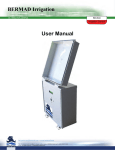
BERMAD Irrigation
FertMaster (pH/EC Interface)
USER MANUAL
VERSIONS : 0.44 & LATER
CONTENTS
1. INTRODUCTION
3
TECHNICAL SPECIFICATIONS
INITIAL STEPS
3
4
SYSTEM CONFIGURATION
4
CALIBRATIONS
4
OPERATION UNDER BIC2000
4
STAND ALONE MODE
5
THE PRINCIPALS OF EC AND PH CORRECTION
5
HOW TO USE THE KEYBOARD
5
THE MENU
5
SYSTEM CONFIGURATION
6
CALIBRATIONS
9
ALARMS DEFINITION
12
FERTILIZER SETS DEFINITION
13
SYSTEM STATUS
15
TECHNICAL DATA DISPLAY
16
ACCUMULATION
16
HARDWARE DESCRIPTION
17
OUTPUT CONNECTIONS
19
DIGITAL INPUTS CONNECTIONS
19
EC pH AND TEMPERATURE SENSORS CONNECTIONS
20
FERTMASTER ADDRESS DEFINITIONS
22
CONTACTS SELECTION BOARD
22
SCREENS LAYOUT
23
FERTMASTER
BIC2000
STAND ALONE
EC-PH INTERFACE
23
24
BERMAD Irrigation
1. Introduction
The FERTMASTER is a highly efficient control unit specially designed for controlling the process of fertilizers injection while maintaining the desired levels of EC and pH of the treated water. The unit is installed as part of an injection setup as a bypass to the mainline.
The FERTMASTER can be used in two working modes: either as a stand alone unit or as an interface controlled by the BIC2000
irrigation controller.
The FERTMASTER is capable of managing simultaneously up to 6 injectors each of which can serve one of the following functions:
• EC control
• pH control
• Inject without pH/EC control, maintaining a desired concentration.
In addition to the 6 injectors the FERTMASTER can control the main valve and the booster pump, can read a water meter and the
fertilizer meters.
The principal of the EC and pH control is implemented by continuously varying the predefined concentrations of the various fertilizers
relatively to the deviation of the actually measured EC and pH values from the desired set-points. The resulting correction factors are
displayed and stored for the next injection process helping the rapid and smooth convergence.
TECHNICAL SPECIFICATIONS
Energy source: 220 or 110 V AC 50/60 Hz
Power: 72 VA
Casing : NEMA 4
Temp range: 0-60 C° (operating)
Outputs: 8 outputs of 24v AC. Booster pump activation by solid state relay.
Digital Inputs: 8 Dry contact inputs- water meter, fertilizer meters. Additional 8 inputs can be added
for selection contacts.
Analog inputs: pH sensor 0-14 , EC sensor 0-10 mSiemens cell constant 1, temperature sensor
PT100.
[email protected] • www.bermad.com
The information herein is subject to change without notice. BERMAD shall not be held liable for any
errors. All rights reserved. © Copyright by BERMAD. 3
BERMAD Irrigation
INITIAL STEPS
The following pages supply the basic information necessary for setting up and using the FERTMASTER assuming that all the hydraulic and electric connections were properly made.
The following paragraph describes the steps of configuration, calibration and parameters setting which must be executed prior to
the first time use:
SYSTEM CONFIGURATION
It is assumed that the working mode whether under BIC2000 control, or as a STAND ALONE unit, is rarely or never changed, therefore the configuration step where the working mode is decided, does not appear on top of the configuration steps. However at the
initial configuration the working mode should be checked prior to the other steps and changed if necessary. When under BIC2000
control, most of the parameters arrive from the BIC2000 controller and cannot be changed via the FERTMASTER panel.
The unit configuration consists of the following steps:
1. Defining the working mode – stand alone or under BIC2000.
2. Defining the number of injectors, the function allocated to each injector and the minimal injection time per each. Defining the
use of output 8 which can serve as a main valve or as an agitator control. When under BIC2000 control, the information can only
be changed at the BIC2000.
3. Defining whether water meter and fertilizer meters are in use and defining theirs ratios. Under BIC2000 control the information
can only be changed at the BIC2000.
4. Defining the upper and lower limits of the predefined concentrations that may change during the control process. The limits
will never be exceeded even if the desired EC/pH set points are not reached. Under BIC2000 control the information can only be
changed at the BIC2000.
5. Defining the functions of the alarm relays if such are being used.
CALIBRATIONS
In order to achieve accurate results, some calibration steps must be executed:
1. The EC sensor calibration – Done by immersing the EC probe into a standard solution with a known EC value. By use of the
key board the value is entered manually into the control unit and the calibration process is started, after some stabilization time
the process terminates with indication of success or failure.
2. The pH sensor calibration – Done in two steps, first the sensor is immersed in a solution of pH=7 and calibrated there to
make sure that the graph passes through the 0 point of the axes. Then another calibration is made using a solution of pH=4 (or
pH=10 in case of basic solutions). The second calibration takes care of the graph’s slope.
3. Determining the injectors flow – The system must be informed about the nominal flow of each fertilizer injector. The injectors
should be adjusted to the minimal flow that is still enough to supply the highest demand at the highest water flow. The system
supplies the software tools for easily measuring these values. The process is based on measuring the time it takes for injecting a
known amount of fertilizer into the system. The process must be repeated per each of the injectors. In case the system contains
flow meters, the measured flow can be found at the second screen of the TECHNICAL information, and should be copied from
there into the FLOW CALIBRATION screens in place of the flow calibration results.
4. Determining the sensors latency – An important parameter that has a great influence on the system’s quality of control is
the sensors latency that defines the delay between the injection time and until the sensor detects the effect of the injection. The
latency is measured twice:
•
First for the lowest expected water flow and second for the highest water flow.
•
The system supplies the software tools for measuring this parameter.
OPERATION UNDER BIC2000
When under BIC2000 command the fertilizer sets reside in the BIC2000 memory and the desired fertilizer set is loaded into the
FERTMASTER along with the other necessary parameters prior to starting the injection process.
The injection process starts by a signal from the BIC2000. Once the fertilizer set is loaded and the injection process started, the injection process is carried out by the FERTMASTER that keeps reporting to the BIC2000 about the progress and about malfunctions
when occur.
4
[email protected] • www.bermad.com
1849 Thunderbolt Drive, Porterville, CA 93257
Tel: 877-577-4283
Fax: 800-839-3884
BERMAD Irrigation
STAND ALONE MODE
The injection process is dictated by a fertilizer set. The fertilizer set is like a formula that contains the desired EC and pH set points,
and for each of the injectors the desired concentration to start with. The fertilizer set contains also the expected nominal water flow
that the system will use until it can measure the real water flow and optionally an amount of pure water to be measured before starting the injection of the fertilizers.
Eight fertilizer sets can be stored in the FERTMASTER’s memory and the selection of the desired fertilizer set to be used for the current process is done by closing one of the eight selection contacts that can be connected as inputs to the FERTMASTER’s selection
contacts board.
The injection process start depends on the start mode selected, the process may start right away when the system senses the closing of one of the selected contacts, or it may start when sensing the flow of water; indicated by a pulse from the water meter. The
process can start manually by the operator.
THE PRINCIPALS OF EC AND PH CORRECTION
At the beginning of the process the injection will be according to the predefined concentrations assuming that the water flow is the
nominal flow and that the predefined concentration of the fertilizers are assumed to give the correct EC and pH values. Later when
the real water flow is measured and after having the actual readings of the pH and EC, the concentration is adjusted in order to bring
the actual values to the desired set-points. The adjustment is done by correction factors one for the EC and one for the pH. The correction factors also known as “Scales”, start with 100% (that means no correction) and are increased or decreased according to the
deviation to be corrected. Defining the permitted range of change of the Scales is part of the configuration process. At the end of
the injection process the last values of the Scales are stored so that the next time the system start with the corrected concentration
values; however, if the user decides to manually adjust the predefined concentration according to the resulting Scales, the adjustment can be done but then the Scales will be readjusted to 100%.
HOW TO USE THE KEYBOARD
The pH/EC INTERFACE is equipped with a keyboard of 5 buttons serving both
the data insertion and the movement between screens. The colored key in the
middle, is the ENTER key, used for changing the function of the other 4 keys
the arrow keys. The data insertion mode is indicated by a blinking black rectangle (Cursor) appearing on the screen in one of the editable fields.
During data insertion the vertical arrows are used for changing the value underneath the cursor, and the horizontal arrows enable the movement of the cursor
between the digits. The ENTER key serves also for confirmation of the inserted
value, and for movement to the next editable field on the screen. After passing the last editable field, the cursor disappears from the screen indicating the
end of the data insertion mode. At this stage the 4 arrow keys can be used for
movement between the screens.
Ground
THE MENU
The list of subjects included in the left most screens of the pH/EC INTERFACE constitutes the main menu from which the desired
subject can be selected. Use the vertical arrows for moving from one subject to another and when the desired subject is reached,
use the right arrow key to move into the list of screens belonging to the selected subject. The main menu can be reached from any
screen by moving repeatedly to the left using the left arrow key.
The subjects included in the main menu are as follows:
• INTRO SCREEN
• STATUS
• SETS DEFINITIONS (STAND ALONE ONLY!!!)
• ACCUMULATION (STAND ALONE ONLY!!!)
• ALARM DEFINITION (STAND ALONE ONLY!!!)
• CONFIGURATION
• CALIBRATION
• TECHNICAL
[email protected] • www.bermad.com
The information herein is subject to change without notice. BERMAD shall not be held liable for any
errors. All rights reserved. © Copyright by BERMAD. 5
BERMAD Irrigation
SYSTEM CONFIGURATION
Configuration
>>>
Whenever you wish to view / change the configuration, select this subject by using the right arrow key.
For making any configuration changes the system requires a password which is 139. Without entering the
password, the existing configuration can be inspected but cannot be changed. Making changes is permitted at any time even during the injection process.
Enter password
139
When entering into the configuration subject we arrive to the internal submenu that can be recognized by
the title “Configuration“ at the upper row and the subtitle at the second row. Use the vertical arrows for
moving between the various subtitles of the submenu.
Configuration
<Outputs>
Number of
Injectors: 4
Injector *1 for:
Injector
*1for:
for:
*pH
control
Injector
*1
*pH
control
*pH control
The FERTMASTER can handle 8 outputs, 6 of them can activate fertilizer injectors, number 7 can be used
for driving a booster pump and number 8 can be used for activating a main valve or an agitator.
Use the right arrow key to view / change the outputs configuration. While under BIC2000 control, the number of injectors, and the function allocated to each injector (EC/PH/CONCENTRATION) is defined at the
BIC2000 but can be viewed at the FERTMASTER, however the nominal flow and the injection pulse width
of each injector are set locally.
The first screen at the outputs menu entry shows the number of injectors controlled by the FERTMASTER.
This is the place where in stand alone mode the number of injectors should be defined. However under
BIC2000 command the number of injectors can only be changed from the BIC2000 during system configuration.
The next screen in the outputs menu entry shows the injectors attribution which defines the function allocated to each injector. Use the vertical arrows for scrolling between the various injectors. Under BIC2000 command the attribution can only be changed from The BIC2000 constants menu. In stand alone mode use the
ENTER key to enable changing the attribute allocated to the selected injector. The possible attributions are:
CONCENTRAT – Injecting proportionally, maintaining the concentration defined in l/m3 without being
influenced by the pH / EC control.
EC CONTROL – Injector participating in the EC control .
pH CONTROL – Injector participating in the pH control .
PH correction:
*Acidic
The next screen at the outputs menu entry only exists when at least one injector has been allocated for pH
control. It shows the type of material used for the pH correction, whether Acidic or Basic. Under BIC2000
command this data can only be changed at the BIC2000 constant menu.
Injector*1
*1for:
for:
Injector
Injector
*1
Min.
*pH
control
*pH 0.5
control
Pulse
Sec
The next screen in the outputs menu entry serves both in stand alone mode and under BIC2000 command
for setting the minimal injection pulse width of the injectors. Use the vertical arrows for scrolling between
the injectors and push the ENTER key to enter/exit edit mode.
Output 8 for:
*Not in use
The last screen at the outputs menu entry shows the use of output No 8 of the FERTMASTER. It can be
used either for a main valve or an agitator. Under BIC2000 command the allocation can only be done from
the BIC2000 during system configuration.
[email protected] • www.bermad.com
1849 Thunderbolt Drive, Porterville, CA 93257
Tel: 877-577-4283
Fax: 800-839-3884
6
BERMAD Irrigation
Configuration
<meters>
The following submenu subject deals with the water and fertilizer meters configuration. To get into the subject screens use the right horizontal arrow. When under BIC2000 control the meters configuration is done at
the BIC2000 only.
WM ratio
0.100 THG/p
When a water meter is in use, its ratio must be defined. The ratio of the water meter indicates how much
volume is represented by each pulse of the water meter.
When under BIC2000 command the water meter can be connected either to the BIC2000 or the FERTMASTER. In both cases the ratio of the water meter will be defined at the BIC2000 but can be viewed at
the FERTMASTER as well. When connected to the FERTMASTER, the pulses of the water meter arriving
to the FERTMASTER are by default transferred immediately to the BIC2000; however, for being able to
read fast rate pulses there is an option to count 10 pulses or 100 pulses before transferring a pulse to the
BIC2000, this way the real pulse rate is divided by 10 or by 100 before being reported to the BIC2000. To
use this option consult our technical staff.
F. meters 123456
In use
+++---
In stand alone mode we need to define whether or not fertilizer meters are in use.
Push the ENTER key and use the horizontal arrow keys to move between the meters and use the vertical
arrows to put a + sign under each meter that exists in the system.
FM
FM *1
*1 ratio
rati
FM
*1
ratio
0.100
THG/p
0.100
THG/p
FM THG/p
*1 rao
0.100
0.100 THG/p
Each of the existing fertilizer meters must have its ratio defined. Use the vertical arrows to reach the desired
fertilizer meter and then push the ENTER key and insert the ratio as indicated on the specific meter.
Configuration
<Alarm relays>
The following submenu subject is available in stand alone mode only. Optionally 3 alarm relays can be
operated by the FERTMASTER unit. Each of the alarm relays can be set to operate in normally open or
normally closed modes, and each of them may be defined to react on various alarm conditions.
Relay
*1
active
Relay
*1
Relay*closed
*1 active
active
state
state
state *closed
*closed
The next screen is where you can set the operation mode of the relays either to normally open or to normally closed mode. Use the vertical arrows for scrolling between the relays and then push the ENTER key
and again use the vertical arrows to select the active state closed or open.
Relay 1 for:
*Low EC *Y
Moving to the following screens to the right we arrive to the screens where we can define the events that
will activate each alarm relay.
The possible alarm causes are:
• Low EC
• High EC
• Low pH
• High pH
• Leakage
• No pulses
• Short circuit
First you need to select the desired relay, use the horizontal arrow keys to get to the desired relay. Use the
vertical arrows to scroll between the various alarm causes. For selecting an alarm cause push the ENTER
key and use the vertical arrow to mark it by the letter “Y”. Push the ENTER again to confirm. Notice that
any alarm relay may have any combination of alarm causes set.
7
[email protected] • www.bermad.com
The information herein is subject to change without notice. BERMAD shall not be held liable for any
errors. All rights reserved. © Copyright by BERMAD. BERMAD Irrigation
Configuration
<concentr .limit>
Concent limit %
-20 (for EC) +20
Configuration
<working mode>
Relay 1 for:
*Low EC *Y
During the EC and pH control process the FERTMASTER is increasing/decreasing the initially defined
concentrations in order to keep the EC and pH set-points. For protecting the system against hazardous
conditions, we need to limit the concentration changes and not to allow them to pass certain percentage.
The FERTMASTER will never exceed these limits.
Concent limit %
-20 (for pH) +20
Separate limits can be set for the concentration changes on the injectors defined for EC
control and for those defined for pH control. Under BIC2000 command this limits can
only be changed from the BIC2000 constants menu.
This is the place where you can choose the working mode whether in “stand alone” mode or under command of a DREAM controller. In stand alone mode you will need to define the way the injection process will
be started. Other decisions to be made at this stage are about the reaction rate of the FERTMASTER when
trying to correct variations of the actual EC and pH from their set-points.
Push the ENTER key and then use the vertical arrows for selecting the desired working mode, whether in
“stand alone” mode or under “DREAM command”.
Confirm by pushing the ENTER key again.
Start mode:
*Cont+WM pulse
In stand alone mode it is necessary to tell the FERTMASTER which of the 8 predefined formula of fertilizers
(fertilizer set) should be used during the next injection process and how would the injection process start.
For the purpose of selecting the desired fertilizer set there are 8 selection contacts against the 8 fertilizer
sets, each contact selects the matching fertilizer set and if the start by “Contact” mode was selected, closing the contact will also start the injection process. If the selected start mode is “Cont+WM pulse”, closing
one of the selection contacts will select the desired fertilizer set but the injection process will start upon
receiving a pulse from the Water Meter.
The screen to the left appears only in stand alone mode, and it is used for selecting the desired start
mode. Push the ENTER key and then use the vertical arrows for selecting the desired start mode, confirm
by pushing the ENTER key again.
EC control mode:
*Normal
The reaction rate of the EC control and pH control can be set to one of the three rates:
• Normal
• Fast
• Slow
pH control mode:
*Fast
By default it is set to “Normal”, however in case a faster reaction is desired the “Fast” mode can be selected, but if the measured value becomes too jumpy the “Normal” or the “Slow” modes should be preferred.
Push the ENTER key and then use the vertical arrows for selecting the desired reaction rate. Confirm by
pushing the ENTER key again.
This completes the configuration process. Do not forget to do the calibrations before starting to use the system for injecting fertilizers.
8
[email protected] • www.bermad.com
1849 Thunderbolt Drive, Porterville, CA 93257
Tel: 877-577-4283
Fax: 800-839-3884
BERMAD Irrigation
CALIBRATIONS
Calibration
>>>
Calibration
<EC sensor>
Set default for
EC sensor? *N
Calibration
<pH sensor>
Enter EC of
buffer 2.76
Set default for
pH sensor? *N
Calibration
<Fert. flow>
Calibrate sensor
At 7.01? *N
Injector *4 flow
Injector
*1
flow
Injector
*1
flow
Enter*1
toflow
start
Injector
Enter
tostart
start
Enter
to
start
Enter to
Calibration
<Sensor latency>
Put probe in
buffer and ENTER
Working 00:23
Enter to stop
Enter flushing
Time 00:00 m:s
Put probe into
7.01 hit ENTER
Insert injected
Volume:0.00g
For testing
Use injector *1
Calibrate sensor
At 4.00? *N
Injector *4 flow
Injector
*1flow
flow
Injector
*1
100.00
G/h
Injector
*1
flow
100.00
G/h
100.00
G/h
100.00 G/h
Open valve with
Low flow: ENTER
Put probe into
4.00 hit ENTER
Shortest sensing
Longest sensing
High flow pH
Low flow pH
High water flow
Low water flow
100.0 gpm
05.0 gpm
For entering into the Calibration subject from the main menu use the right horizontal key. After entering into the Calibration subject
we arrive to the internal submenu that can be recognized by the title “Calibration“ at the upper row and the subtitle at the second
row. Use the vertical arrows for moving between the various subtitles in order to reach the desired calibration you want to make.
Calibration
<EC sensor>
The calibration of the EC sensor is done by immersing the EC probe into a standard solution whose EC
value is known and by telling the control unit the expected value. After starting the process the unit takes
some stabilization time and the process terminates with indication of success or failure.
Set default for
EC sensor? *N
In case there is no standard calibration fluid available the default factory calibration value can be used. This
option should be used only when there is no better solution.
Enter EC of
buffer: 2.76
This is where you need to insert the EC of the calibration solution you
are using. Push the ENTER key, insert the value and confirm by another
ENTER.
Put probe in
buffer and ENTER
Immerse the sensor inside the solution and press the ENTER key to start
the calibration process.
During the calibration process the system displays the elapsed time and eventually it indicates success or
failure.
9
[email protected] • www.bermad.com
The information herein is subject to change without notice. BERMAD shall not be held liable for any
errors. All rights reserved. © Copyright by BERMAD. BERMAD Irrigation
Calibration
<pH sensor>
Set default for
pH sensor? *N
The aging effect of the electrode and a degree of contamination which are unavoidable, make it important
that a calibration procedure be carried out regularly. For calibration two buffers of different pH values are
necessary. First the sensor is immersed in a solution of pH=7 and calibrated there to compensate for
the electrode offset to make sure that the graph passes through the 0 point of the axes. Then another calibration is made using a buffer of pH=4 (or pH=10 in case of basic solutions). The second calibration takes
care of the graph’s slope.
In case there are no standard calibration buffers available, the default factory calibration values can be
used. This option should be used only when there is no better solution.
Calibrate sensor
at 7.01? *N
At the first step of calibration this question should be answered positively.
Push the ENTER key, change the selected answer into “Y” and confirm
by another ENTER.
Put probe into
7.01 hit ENTER
As a result you will be asked to immerse the pH probe into the calibration
buffer of 7.01. After hitting the ENTER key the calibration is started. During
calibration the elapsed time is displayed and eventually success or failure is
declared.
Calibrate sensor
at *4.00 ? *N
At the first step of calibration this question should be answered positively.
Push the ENTER key, change the selected answer into “Y” and confirm
by another ENTER.
Put probe into
4.00 hit ENTER
As a result you will be asked to immerse the pH probe into the calibration
buffer of 4.0. After hitting the ENTER key the calibration is started. During
calibration the elapsed time is displayed and eventually success or failure is
declared.
Calibration
<Fert. flow>
The flow of each of the fertilizer injectors must be accurately calibrated. Notice that during the injection process the calculations rely on the calibrated flow.
Optionally when the system is equipped with fertilizer meters, the flow measured by the meters can be
manually inserted, replacing the calibration results.
The flow calibration process is based on measuring the time it takes for injecting a
known amount of fluid into the system.
Prepare a known amount of fluid in a measuring jug with scaling marks.
Injector *1 flow:
Enter to start
Use the vertical arrow keys to select the desired Injector, inset the suction tube of the
injector into the jug and make sure it reaches close to the bottom. When ready push the
ENTER key.
Working 00:23
ENTER to stop
During the suction process the elapsed time is counted and displayed. Let the suction
continue until the jug is almost empty and then push the ENTER key again. Measure the
remaining amount of fluid and calculate the injected volume. Insert the result at the following screen:
Insert injected
Volume: 0.000 L
The process must be repeated per each of the injectors.
10
[email protected] • www.bermad.com
1849 Thunderbolt Drive, Porterville, CA 93257
Tel: 877-577-4283
Fax: 800-839-3884
BERMAD Irrigation
Calibration
<Sensor latency>
The sensor’s latency defines the time it takes between the moment of injection and until the sensors detect
the result of the injection. Knowing the latency is important for the stability of the control process. Since the
latency is influenced by the water flow in the main line, it is measured at two points – at the lowest flow and
the highest flow and between this points an interpolation takes place.
Enter flushing
time 00:00 m:s
Prior to starting the latency measuring, the pipes should be flushed by pure water.
The user can decide how much time he allocates for the flushing.
For testing
Use injector *1
Any of the injectors can be used for the latency measuring. Push the ENTER key and use the vertical arrows for selecting the desired injector and confirm by ENTER.
Open valve with
Low flow. ENTER
For measuring the latency the user is requested to open the valve with the lowest (highest) flow, after
opening, hit the ENTER key to start the process. During the process the display shows the steps being
executed.
The process consists of the following steps:
• Waiting for the flushing time to finish.
• When a water meter is connected to the FERTMASTER, waiting for 2 pulses of the water meter in
order to be able to calculate the lowest (highest) flow. When finished, the resulting flow is displayed.
• Injecting a pulse of fertilizer by the selected injector and starting to measure the time until the sensor reacts to the injected pulse.
• Displaying the results. The results can be edited therefore when there is no water meter included,
the minimal (maximal) flow can be manually inserted.
The first screen shows the measured flow. Use the down arrow key to get to the second screen that
shows the measured latency. Another hit on the down arrow brings us to a third screen in which a pH correction factor can be defined.
When is the pH correction factor needed?
Sometimes due to chemical reactions in the water, although the pH set-point is perfectly kept during the
whole injection process, the pH measured in the water collected at the drippers or sprinklers is higher than
the set-point. The correction factor is used for compensating for this difference.
[email protected] • www.bermad.com
The information herein is subject to change without notice. BERMAD shall not be held liable for any
errors. All rights reserved. © Copyright by BERMAD. BERMAD Irrigation
ALARMS DEFINITION
Several tools are given for protecting the system against improper injections. As mentioned above during the configuration process
we can set “concentration limits” that will not allow the predefined concentrations to reach dangerous values. When the concentration limits are reached the system will not allow passing those limits, and this may cause the value of the EC or pH to be far from its
set-point. For this purpose, deviation limits can be defined so that when the EC or pH values are out of the range for longer than a
predefined time, a fault will be reported and an alarm flag will be raised. The current paragraph deals with the definition of these parameters along with fertilizer leakage threshold and no-pulse detection period definition. This subject appears only when the FERTMASTER is functioning in standalone mode, while under BIC2000 command these functions are fulfilled by the BIC2000 controller.
Alarm definition
Alarm definition
<EC>
EC Deviation
-20% +20%
Alarm definition
<pH>
Alarm definition
<Burst / no flow>
Low EC
m:s
duration 05:00
pH Deviation
-20% +20%
Fert. leakage
threshold 5 pls
High EC m:s
duration 03:00
Low pH
m:s
duration 05:00
High pH m:s
duration 03:00
No fert. pulses
period 02:00 m:s
Select “Alarm definition” of the main menu and use the right arrow key to move one screen to the right. You arrive to the submenu of
the Alarms definition. The vertical arrows can be used for scrolling between the various options.
Alarm definition
<EC>
Alarm definition
<pH>
EC Deviation
-20% +20%
pH Deviation
-20% +20%
High EC m:s
duration 03:00
High pH m:s
duration 03:00
Because of the similarity of the two subjects we shall describe them in parallel.
Use the right arrow key to get into the subjects.
The lower (-) and upper (+) limits of deviation of the EC and pH values are set as a
percentage from the target setpoint.
Use the ENTER key to get into edit mode, insert the desired lower limit, confirm
by ENTER, insert the desired upper limit and use the ENTER key again to exit edit
mode.
Defining how long will the system tolerate a too low EC or pH values before
declaring an alarm condition. Use the Enter key to get into edit mode, insert the
desired time and confirm by another ENTER.
Defining how long will the system tolerate a too high EC or pH values before
declaring an alarm condition. Use the Enter key to get into edit mode, insert the
desired time and confirm by another ENTER.
Alarm definition
<Burst / no flow>
This subject of the submenu exists only when at least one of the injectors has fertilizer meters defined. Use
the right arrow key to get into the subjects.
Fert. leakage
threshold 5 pls
Defining the number of illegal pulses (arriving while the injector is stopped) that will indicate a fertilizer leakage problem. Use the Enter key to get into edit mode, insert the desired number of pulses and confirm by
another ENTER.
No fert. pulses
period 02:00 m:s
Defining the delay since starting the injection and until declaring “No flow” failure if no pulse arrives from
the fertilizer meter. Use the Enter key to get into edit mode, insert the desired delay and confirm by another
ENTER.
12
[email protected] • www.bermad.com
1849 Thunderbolt Drive, Porterville, CA 93257
Tel: 877-577-4283
Fax: 800-839-3884
BERMAD Irrigation
FERTILIZER SETS DEFINITION
When the FERTMASTER is defined to work in stand alone mode, the user expresses his requirements from the system by defining
FERTILIZER SETS. Up to 8 fertilizer sets can be stored in the FERTMASTER’s memory. Against the 8 fertilizer sets there are 8 selection contacts connected as inputs to the FERTMASTER. By closing a contact, the appropriate fertilizer set is selected. The fertilizer
set contains the following information:
• The target set-points of the EC and pH.
• The desired concentration of each of the fertilizers to be injected.
• For the injectors that do not participate in the EC and pH control process but are injecting
• volumetrically, the mode of injection (Bulk or Proportional) and the amount of injection has to be defined.
• The amount of pure water before injection.
• The nominal water flow to be considered when having no ability of measuring the actual flow.
• This happens when there is no water meter in use, or when we have not yet received 2 pulses from the water meter without
which the flow cannot be calculated.
• The correction scales for the EC and pH. By default the correction scales are set to 100% (no correction) but during the
injection process the scales may vary and thus adjust the concentration of the fertilizers, keeping the actual values of the
EC and pH as close as possible to the target setpoints.
• The correction scales by which the previous injection terminated, are used at the beginning of the next injection, making use
of what was learned during the previous process.
Sets definitions
When being at the sets definition screen of the main menu use the right horizontal arrow key to get into the
subject.
Target
pH: 5.7
The first screen deals with the definition of the target EC and pH set-points. At this stage the vertical arrows enable arriving to the desired fertilizer set. Use the ENTER key to get into edit mode and after setting
the desired EC and pH set points confirm by hitting the ENTER key again. In case any of the set points is
not applicable, set it to 00.0, on the display the word “skip” will indicate the fact that the particular set-point
is not defined.
*S1 Injector *3
*Prop:
*Dose
The screen that deals with the selection of the desired injection mode whether proportional or bulk appears
only if at least one of the injectors was defined as working by “Concentration” and not by EC or pH. Only
for these injectors the user can decide the desired injection mode and is able to define a dosage that when
reached, the injection terminates. The other injectors will always have a concentration defined, this concentration will be adjusted by the correction scales through the EC/pH control and there is no dosage that can
be defined.
*S1
EC: 2.1
Push the ENTER key to get into edit mode and use the vertical arrows to select the desired injector. Another hit of the ENTER key will enable selection of the injection mode- Prop stands for proportional injection
and Bulk means continuous injection. Another hit of the ENTER key will enable selecting between Dose /
No dose. Push the ENTER key to exit edit mode. Repeat this procedure for all the injectors defined to work
by “Concentration”
13
[email protected] • www.bermad.com
The information herein is subject to change without notice. BERMAD shall not be held liable for any
errors. All rights reserved. © Copyright by BERMAD. BERMAD Irrigation
*S1 Injector *3
Dosage 12.5 G
This screen appears only for those injectors that were defined to supply a certain dosage of fertilizer and
terminate the injection. Push the ENTER key and use the vertical arrows to select the desired injector. Push
the ENTER key again and insert the desired dosage. Hit the ENTER key again to exit edit mode. Repeat
this procedure for all the injectors defined to supply a certain dosage.
*S1 Water before
2.0 THG
When it is required to supply some pure water prior to the fertilizers injection, the quantity of “Water before”
can be defined. The system will start injecting fertilizers only after the specified amount of water was supplied. Push the ENTER key to get into edit mode, insert the desired amount of water before fertilization,
and push the ENTER key again to exit edit mode.
*S1 Nominal W.
flow 400.0 GPM
Because all the fertilizer demands are defined as volumetric proportions, calculations of the water volumes
make use of the water flow. Knowing the nominal water flow is important while there is no ability of measuring the actual flow. The system uses this information in one of the following cases: when there is no water
meter in use, or when we have not yet received 2 water pulses, therefore the flow calculation is prohibited.
Push the ENTER key to get into edit mode, insert the desired nominal water flow, and push the ENTER key
again to exit edit mode.
*S1
EC:108
The correction scales of the EC and pH are used by the system as multiplication factors by which the
predefined concentrations of the fertilizers are adjusted. By default the correction scales are set to 100%
(no correction) but during the process when the actual values of the EC or the pH are away from the target
set-points, the scales will change in order to adjust the concentration of the fertilizers, bringing the actual
values of the EC and pH as close as possible to the target set-points. When the process terminates, the
last correction scales are remembered in order to be used at the beginning of the next injection, making
use of the knowledge obtained at the previous process. Use the ENTER key to get into edit mode and after
setting the desired scales of the EC and pH hit the ENTER key again.
Scales
pH:94 %
14
[email protected] • www.bermad.com
1849 Thunderbolt Drive, Porterville, CA 93257
Tel: 877-577-4283
Fax: 800-839-3884
BERMAD Irrigation
SYSTEM STATUS
The various status screens supply valuable information about the activity of the system including the statuses of the fertilizer sets,
the current and the average values of the EC and pH, the values of the correction scales, the current concentration and current
accumulation of each of the fertilizers. The information is updated online. When there exist failures in the system, in the main menu
the second row of the status screen will indicate “<<<Failures”. Use the left arrow key to get information about the kinds of failures
recorded. In order to clear a failure status push the ENTER key select the answer “y” when asked about clearing the failure, and
confirm by a second ENTER.
Status>>>
<<<Failures
S1: Running -EC: 2.1 pH: 5.1
I - + - - + - - -W.Flow
O + + - - - - - + 18.20
Current Scales:
EC=105 pH= 88 %
Planned EC : 2.2
Average EC : 2.2
Planned pH : 5.6
Average pH : 5.6
Inj*1 0.50 l/m3
Accum 1.2 ltr
*S1 Water before
2.0 THG
When being at the status screen of the main menu use the right horizontal arrow key to get into the subject.
S1: Running -EC: 2.1 pH: 5.1
The first status screen shows the statuses of the various fertilizer sets along with the temporary averages
of the EC and pH. Use the vertical arrows to move from one set to another. The temporary averages are
calculated within a moving time window that contains a number of samples measured during the last few
seconds. When the Alarm output is activated it will be indicated by the letter A at the upper right corner of
the screen.
I - + - - + - - -W.Flow The second status screen shows the statuses of the inputs, the outputs and the rate of the water flow. The
O + + - - - - - + 18.20 screen can also be used for manual activation of the outputs for testing. The upper row shows the status
of the dry contact inputs, each input with an open contact is indicated by a “-“ sign and a closed contact
by a “+” sign. The bottom row shows the status of the outputs. The activated outputs are marked by”+”
sign. The water flow is shown at the right side of the screen. When the display shows the nominal flow it
will be indicated as “Nominal”. In order to manually activate outputs, push the ENTER key, use the horizontal keys to get to the desired output and by the upper arrow you can turn the output ON and OFF. To exit
edit mode push the ENTER key again. Once an output is turned ON it is the user’s responsibility to turn it
off again.
Current Scales:
EC=105 pH= 88 %
As explained above, the correction scales are used for adjusting the predefined concentrations of the
fertilizers used for the EC and pH control in order to bring the actual EC and pH values to their target setpoints. The current screen appears only while the control process is in progress.
Planned EC : 2.2
Average EC : 2.2
The next two screens show the average values of the EC and pH versus the target set-points.
The average displayed here is the average of the whole injection process since it was last started, and it
should not to be confused with the temporary average of the moving time window shown in the first status
screen. Also these screens appear only while the control process is in progress.
Planned pH : 5.6
Average pH : 5.6
Inj*1 0.50 G/THG
Accum
1.2 G
The last status screen reports about the performance of each of the injectors during the last injection
process. For each injector the actual concentration reached and the amount of fertilizer supplied will be
indicated. Also this screen appears only while the control process is in progress.
15
[email protected] • www.bermad.com
The information herein is subject to change without notice. BERMAD shall not be held liable for any
errors. All rights reserved. © Copyright by BERMAD. BERMAD Irrigation
TECHNICAL DATA DISPLAY
For engineering purposes some more technical data can be obtained.
Technical
>>>
Sensor temp: 24.9
EC= 1.0 pH= 7.0
EC: window 14.2
Latency 20.0 sec
pH: window 25.1
Latency 30.0 sec
Stop reason:
Stopped by Dream
Fertilizer
*1
flow
Fertilizer
*1
flow
Fertilizer
100.00
*1
G/h
flow
Fertilizer
*1
flow
100.00
G/h
100.00
G/h
100.00 G/h
Select from the main menu the screen which says “Technical” and use the right horizontal arrow key to get
into the subject. Keep moving to the right to scan all the technical information.
Technical
>>>
Sensor temp: 24.9
EC= 1.0 pH= 7.0
EC: window 14.2
Latency 20.0 sec
The first screen of the technical information shows the actual readings of the EC sensor, the pH sensor
and the temperature sensor. The temperature sensor is used for temperature compensation. The values
displayed are without any averaging.
pH: window 25.1
Latency 30.0 sec
Stop reason:
Stopped by Dream
The next two screens show two important parameters used by the EC and pH
control mechanisms. One is the averaging window length. The averages of the
samples included in these windows are taken into consideration while deciding
about the correction scales.
The second parameter is the latency between the moment of injection and until
the result can be sensed.
The next screen describes the cause of the last injection’s stop.
The last screen included in the technical information category is the fertilizers flow screen.
This screen appears only when at least one fertilizer meter exists in the system. Use the vertical arrows to
scroll between the various fertilizer’s flow rates.
Fertilizer *1 flow
100.00 l/h
ACCUMULATION
For engineering purposes some more technical data can be obtained.
Accumulation
Accumulation
*S1 Last Average
EC 2.1
W. Last: 82.5
Total: 12773 m3
*S1
Last
Average
*S1
Last
Average
*S1
Last
Average
2.1
*S1EC
Last
Average
EC
2.1
EC
EC2.1
2.1
*S1
Last
Average
*S1
Last
Average
*S1
Last
Average
5.1
*S1pH
Last
Average
EC
2.1
EC
EC2.1
2.1
pH: window 25.1
Latency 30.0 sec
W. Last: 82.5
Total: 12773 m3
*F1 Last:
7.3
Fertilizer
*1
flow
Fertilizer
Total:
245.1
*1
flow
L
Fertilizer
*1
flow
100.00
G/h
100.00
G/h
100.00 G/h
Select from the main menu the screen which says “Accumulation” and use the right horizontal arrow key to
get into the subject. Keep moving to the right to scan all the accumulation screens.
*S1 Last Average
pH 5.1
The first two screens store the last averages of the EC and pH for each of the
fertilizer sets when they were last operating. Use the vertical arrows for scrolling
between the sets.
*F1 Last: 7.3
Total: 245.1 L
The last two screens deal with the last accumulation and the total accumulation
of the water meter and the last accumulation and total accumulation of each
of the fertilizer meters. Use the vertical arrows for scrolling between the various
fertilizer meters.
16
[email protected] • www.bermad.com
1849 Thunderbolt Drive, Porterville, CA 93257
Tel: 877-577-4283
Fax: 800-839-3884
BERMAD Irrigation
HARDWARE DESCRIPTION
The following picture shows an external view of the FERTMASTER.
The internal view shows the various parts of the system.
CPU
Main I/O
Power Supply
pH Sensor
interface
EC Sensor
interface
Set selection
contacts
Main power
Fuse (2A)
17
[email protected] • www.bermad.com
The information herein is subject to change without notice. BERMAD shall not be held liable for any
errors. All rights reserved. © Copyright by BERMAD. BERMAD Irrigation
The following picture shows the main I/O board explaining the function of its main parts.
Connector for communication
with PC for software updating
and data display
Leds indicating communication
problem with the EC pH
interfaces or hardware problems
Address switch
Supply of 12v AC
for the electronics
Led indicating 12V
AC Exist
Selection contacts
board connector
Led indicating
24v AC exist
24v AC 4A fuse
Supply of 24v
AC for outputs
Leds indicating
active output
Outputs
terminal block
Inputs
terminal block
18
[email protected] • www.bermad.com
1849 Thunderbolt Drive, Porterville, CA 93257
Tel: 877-577-4283
Fax: 800-839-3884
BERMAD Irrigation
OUTPUT CONNECTIONS
The following picture shows the outputs terminal block. The first six outputs are used for activating the fertilizer injectors, output 7 is
for the booster pump and output No 8 is for activating a Main Valve or alternatively for activating an Agitator. When under DREAM
command the Main-Valve/ Agitator can be connected into the BIC2000 I/O boards instead of the FERTMASTER.
Notice that each output device (solenoid) is connected to the terminal block by 2 wires. The polarity has no importance. All the terminals have one common wire interconnected on the board; it is marked by the letter “c”.
DIGITAL INPUTS CONNECTIONS
The terminal block of the digital inputs is arranged in two rows one above the other. Each row contains 4 inputs, the odd numbered
inputs at the bottom row and the even numbered inputs at the upper row. Each pair of inputs has one common terminal marked by
the letter “G”. The first 6 inputs are used for the fertilizer meters. Input 8 is used for the water meter, and input 7 is not in use. The
picture below shows for example how Fertilizer Meters No 1 and No 3 should be connected.
FM 1
FM 2
19
[email protected] • www.bermad.com
The information herein is subject to change without notice. BERMAD shall not be held liable for any
errors. All rights reserved. © Copyright by BERMAD. BERMAD Irrigation
EC pH AND TEMPERATURE SENSORS CONNECTIONS
The EC, pH and the temperature sensors are connected to the FERTMASTER through interface boards.
The interface boards are connected to the CPU board by a flat cable plugged into each of the boards. Each of the interface boards
has a red led that blinks every second while the communication with the CPU board is functioning normally. The original design took
into consideration 2 interfaces of EC and 2 of pH sensors; therefore, each of the interface boards contains an address selection
jumper. Currently only one sensor of each type is recognized by the software, therefore the address selection jumpers should be set
to 1 as shown in the pictures below.
Notice that the pH sensor acts like a battery that generates a DC voltage that depends on the acidity of the
measured fluid, therefore the sensor has a polarity and this polarity must be taken in consideration while
connecting the sensor to the board. The pH sensor is supplied with a shielded cable, the shield is negative
and should be connected to the terminal marked as (-) while the inner cord should be connected to the (+)
terminal.
When the shield is covered and cannot be seen, the colors of the wires indicate the polarity; black wire - the
negative and red wire - positive.
The EC sensor and the temperature sensor have no polarity; therefore the order of connection of the
cords is insignificant as long as you don’t mix between the sensors.
In many cases the EC and temperature sensors arrive as one unit that contains both sensors. This unit will
have 2 wires for the EC sensor and 2 for the temperature sensor.
Usually there will be a marking to indicate which pair of wires belongs to the EC sensor and which pair to
the temperature sensor, however there is a way to find out which pair of wires belongs to the temperature
sensor in case the marking is missing.
The temperature sensor is of the type known as PT100 which has a resistance of about 100 Ohms so by
measuring the resistance between the wires the pair that shows a resistance of 100 Ohms belongs to the
temperature sensor.
20
[email protected] • www.bermad.com
1849 Thunderbolt Drive, Porterville, CA 93257
Tel: 877-577-4283
Fax: 800-839-3884
BERMAD Irrigation
The pH terminal.
Notice the polarity
Blinks when
communication is OK
Address selection
jumper set to addr 1
The flat cable
connector
Temperature and
EC terminal
Blinks when
communication is OK
Address selection
jumper set to addr 1
The flat cable
connector
21
[email protected] • www.bermad.com
The information herein is subject to change without notice. BERMAD shall not be held liable for any
errors. All rights reserved. © Copyright by BERMAD. BERMAD Irrigation
FERTMASTER ADDRESS DEFINITIONS
When defined to work under DREAM command the FERTMASTER is just another interface
connected to the DREAM, and like all other interfaces it needs to have a unique address by
which it will be recognized by the DREAM during communication. The address is set by the
address switch using a binary code. When a dip switch is raised to the ON position it indicates
“1”. Use the table below for conversion.
DECIMAL
ADDRESS
1
2
3
4
5
6
7
8
BINARY VALUE TO BE SET BY THE DIP
SWITCH POSITIONS:
Pos 1 Pos 2 Pos 3 Pos 4 Pos 5 Pos 6
1
0
0
0
0
0
0
1
0
0
0
0
1
1
0
0
0
0
0
0
1
0
0
0
1
0
1
0
0
0
0
1
1
0
0
0
0
0
1
1
1
0
0
0
0
1
0
0
CONTACTS SELECTION BOARD
When the FERTMASTER is used in the stand-alone mode, it has to be added the selection contacts board to which 8 dry contacts
can be connected. The selection contacts enable selecting one of the 8 predefined fertilizer sets to be used during the injection
process. The selected fertilizer set contains the definitions of the required concentrations of the fertilizers and the desired set-points
of EC and pH.
The way to connect
the 8 selection
contacts
The selection contacts board contains also 3 alarm outputs that can be set to be activated in various alarm conditions.
22
[email protected] • www.bermad.com
1849 Thunderbolt Drive, Porterville, CA 93257
Tel: 877-577-4283
Fax: 800-839-3884
BERMAD Irrigation
SCREENS LAYOUT
FERTMASTER
pH controller
Talgil VXX
Stand Alone
Status>>>
<<<Failures
S1: Running -EC: 2.1 pH: 5.1
I - + -- + - -- W.Flow
O + + ---- - + 18.20
Current Scales:
EC=105 pH= 88 %
Sets definitions
*S1
Target
*S1
*S1 2.1Target
Target
EC:
pH: 5.7
*S1 2.1 Target
EC:
EC: 2.1 pH:
pH:5.7
5.7
EC: 2.1 pH: 5.7
*S1
Injector *3*3
*S1
*S1 Injector
Injector
*3
*Prop:
*Dose
*S1 Injector
*3
*Prop:
*Dose
*Prop:
*Dose
*Prop:
*Dose
*S1
Injector
*3*3
*S1
Injector
*S1 l/m3
Injector
*3
0.50
(conc)
*S1 l/m3
Injector
*3
0.50
(conc)
0.50 l/m3 (conc)
0.50 l/m3 (conc)
*S1
Injector *3*3
*S1
*S1 Injector
Injector
Dosage
12.5 LL*3*3
*S1 Injector
Dosage
Dosage 12.5
12.5 L
Dosage 12.5 L
Accumulation
*S1
Last
Average
*S1
Last
*S12.1
LastAverage
Average
EC
*S12.1
Last Average
EC
EC 2.1
EC 2.1
*S1
Last
Average
*S1
Last
*S15.1
LastAverage
Average
pH
*S15.1
Last Average
pH
pH 5.1
pH 5.1
W. Last: 82.5
Total: 12773 m3
*F1
Last: 7.3
*F1
7.3
*F1 Last:
Last:
Total:
245.17.3
*F1 Last:
7.3L
Total:
Total: 245.1
245.1 LL
Total: 245.1 L
Alarm definition
Alarm definition
<EC>
EC Deviation
-20% +20%
Alarm definition
<pH>
Configuration
>>>
Low EC
m:s
duration 05:00
pH Deviation
-20% +20%
Alarm definition
<Burst / no flow>
Fert. leakage
threshold 5 pls
Set default for
pH sensor? *N
Calibration
<Fert. flow>
Calibration
<Sensor latency>
Technical
>>>
Sensor temp: 24.9
EC= 1.0 pH= 7.0
Enter EC of
buffer: 2.76
EC: window 14.2
Latency 20.0 sec
WM ratio
0.100 m3/p
Relay 1 for:
*Low EC
*Y
*S1
Scales
*S1
*S1 Scales
Scales
EC:108
pH:94 %%
*S1 Scales
EC:108
EC:108 pH:94
pH:94 %
EC:108 pH:94 %
Injector *4 min.
Injectorpulse
*3min.
min.
Injector
*2min.
1.0 sec
Injector
*1
pulse1.0
1.0sec
sec
pulse
pulse
1.0 sec
F. meters 123456
In use + + + -- -
Relay 2 for:
*High pH
*Y
Relay 3 for:
*Leakage
*Y
Output 8 for:
*Not in use
FM
*1 ratio
FM
ratio
FM *2*3
0.100
l/p ratio
FM
*4 ratio
0.100
0.100l/pl/p
0.100 l/p
Concent limit %
-20 (for pH) +20
Current model
*Dream Command
Start mode:
*Cont+WM pulse
EC control mode:
*Normal
pH control mode:
*Fast
Put probe in
buffer and ENTER
Calibrate sensor
at 7.01? *N
Injector *4 flow:
Injector
*4flow:
flow:
Enter
to start
Injector
*2flow:
Injector
*1
Enter
tostart
start
Enter
Enter
totostart
pH correction:
*Acidic
Water meter is
*In use
Concent limit %
-20 (for EC) +20
Configuration
<working mode>
Calibration
<pH sensor>
*Injector*3*4for:for:
Injector
Injector
for:
*Concentrat
Injector
*1*2for:
*Concentrat
*Concentrat
*Concentrat
Relay
Relay *1*1 active
active
Relay *closed
*1 active
state
state *closed
state *closed
Configuration
<concentr.limit>
Set default for
EC sensor? *N
*S1
Nominal W.
*S1
W.
*S1 Nominal
Nominal
W.
flow
m3/h
*S1 40.0
Nominal
W.
flow
flow 40.0
40.0 m3/h
m3/h
flow 40.0 m3/h
TALGIL COMPUTING & CONTROL LTD.
High pH
m:s
duration 03:00
Number of
injectors: 4
Configuration
<Alarm relays>
Calibration
<EC sensor>
*S1
Water
before
*S1
Water
before
*S1 2.0
Water
before
m3
*S1 2.0
Water
before
m3
2.0 m3
2.0 m3
No fert. pulses
period 02:00 m:s
Configuration
<meters>
Calibration
>>>
Inj*1 0.50 l/m3
Accum 1.2 ltr
Planned pH : 5.6
Average pH : 5.6
High EC
m:s
duration 03:00
Low pH
m:s
duration 05:00
Configuration
<outputs>
Enter password
139
Planned EC : 2.2
Average EC : 2.2
Calibrate sensor
at 4.00 ? *N
Injector *4 flow
Injector*2
*4flow
flow l/h
Injector
Injector
*1100.00
flow
100.00
l/h
100.00
100.00
l/hl/h
Enter flushing
time 00:00 m:s
For testing
Use injector *1
pH: window 25.1
Latency 30.0 sec
Stop reason:
Stopped by Dream
Open valve with
Low flow. ENTER
Open valve with
High flow. ENTER
Longest sensing
latency
10.0
Low flow
pHsec
correction
0.2
Low
water flow:
05.0 m3/h
Shortest sensing
latency
High
flow8.5
pHsec
correction
0.4
High
water flow:
20.0 m3/h
Fertilizer
*1 flow
Fertilizer*2
flow
Fertilizer
*3
100.00
l/hl/h
Fertilizer
*4flow
flow
100.00
100.00
100.00l/hl/h
23
[email protected] • www.bermad.com
The information herein is subject to change without notice. BERMAD shall not be held liable for any
errors. All rights reserved. © Copyright by BERMAD. BERMAD Irrigation
BIC2000
EC-PH INTERFACE
TALGIL COMPUTING & CONTROL LTD.
24
[email protected] • www.bermad.com
1849 Thunderbolt Drive, Porterville, CA 93257
Tel: 877-577-4283
Fax: 800-839-3884
BERMAD Irrigation
25
[email protected] • www.bermad.com
The information herein is subject to change without notice. BERMAD shall not be held liable for any
errors. All rights reserved. © Copyright by BERMAD. BERMAD
Hydraulic Control Valves
BERMAD
Waterworks
BERMAD
Fire Protection
[email protected] • www.bermad.com
BERMAD
Agricalture
The information herein is subject to change without notice. BERMAD shall not be held liable for any errors. All rights reserved. ©
Copyright by BERMAD. BERMAD
Landscape


