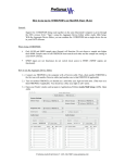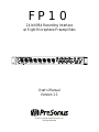
1
FP10 24-bit/96k Recording Interface w/ Eight Microphone Preamplifiers User’s Manual Version 1.1 © 2007, PreSonus Audio Electronics, Inc. All Rights Reserved. PRESONUS LIMITED WARRANTY PreSonus Audio Electronics Inc. warrants this product to be free of defects in material and workmanship for a period of one year from the date of original retail purchase. This warranty is enforceable only by the original retail purchaser. To be protected by this warranty, the purchaser must complete and return the enclosed warranty card within 14 days of purchase. During the warranty period PreSonus shall, at its sole and absolute option, either repair or replace, free of charge, any product that proves to be defective on inspection by PreSonus or its authorized service representative. To obtain warranty service, the purchaser must first call or write PreSonus at the address and telephone number printed below to obtain a Return Authorization Number and instructions of where to return the unit for service. All inquiries must be accompanied by a description of the problem. All authorized returns must be sent to the PreSonus repair facility postage prepaid, insured and properly packaged. PreSonus reserves the right to update any unit returned for repair. PreSonus reserves the right to change or improve the design of the product at any time without prior notice. This warranty does not cover claims for damage due to abuse, neglect, alteration or attempted repair by unauthorized personnel, and is limited to failures arising during normal use that are due to defects in material or workmanship in the product. Any implied warranties, including implied warranties of merchantability and fitness for a particular purpose, are limited in duration to the length of this limited warranty. Some states do not allow limitations on how long an implied warranty lasts, so the above limitation may not apply to you. In no event will PreSonus be liable for incidental, consequential or other damages resulting from the breach of any express or implied warranty, including, among other things, damage to property, damage based on inconvenience or on loss of use of the product, and, to the extent permitted by law, damages for personal injury. Some states do not allow the exclusion of limitation of incidental or consequential damages, so the above limitation or exclusion may not apply to you. This warranty gives you specific legal rights, and you may also have other rights, which vary from state to state. This warranty only applies to products sold and used in the United States of America. For warranty information in all other countries please refer to your local distributor. PreSonus Audio Electronics, Inc. 7257 Florida Blvd. Baton Rouge, LA 70806 www.PreSonus.com © 2007, PreSonus Audio Electronics, Inc. All Rights Reserved. TABLE OF CONTENTS 1 OVERVIEW 1.1 1.2 1.3 1.4 Introduction ........................................................................................................................................... Features ................................................................................................................................................ What is in the Box ................................................................................................................................. System Requirements ............................................................................................................................. 3 4 5 6 2 OPERATION 2.1 Quick Start Up ....................................................................................................................................... 7 2.1.1 Installation in Microsoft Windows .................................................................................................. 7 2.1.2 Installation in Mac OS X .............................................................................................................. 10 2.1.3 Cubase LE – Device Setup ............................................................................................................ 11 2.1.4 Cubase LE – Creating a Project .................................................................................................... 13 2.2 Sample Hookup Diagram ..................................................................................................................... 15 2.3 Microphones ........................................................................................................................................ 16 2.3.1 Condenser .................................................................................................................................... 16 2.3.2 Dynamic ...................................................................................................................................... 16 2.3.3 USB and other types .................................................................................................................... 16 2.4 Using The Preamp Output and Line Input as an Insert .......................................................................... 17 3 CONTROLS & CONNECTIONS 3.1 FP10 Control Panel ............................................................................................................................. 3.1.1 FP10 Advanced Settings .............................................................................................................. 3.1.2 FP10 Hardware Settings .............................................................................................................. 3.2 Front Panel Layout .............................................................................................................................. 3.3 Back Panel Layout ............................................................................................................................... 17 17 18 20 23 4 TECHNICAL INFORMATION 4.1 Troubleshooting ................................................................................................................................... 25 4.2 Specifications ...................................................................................................................................... 27 OVERVIEW 1.1 INTRODUCTION Thank you for purchasing the PreSonus FP10. PreSonus Audio Electronics has designed the FP10 utilizing high-grade components to insure optimum performance that will last a lifetime. Loaded with 24-bit 96K converters, eight PreSonus microphone preamplifiers and Cubase LE 48-track recording software, the FP10 is ready to go out of the box for professional quality computer recording. All you need is a computer with FireWire connection, a few microphones and cables along with your instruments and you are ready to record! We encourage you to contact us at 225-216-7887 with any questions or comments you may have regarding your PreSonus FP10. PreSonus Audio Electronics is committed to constant product improvement, and we value your suggestions highly. We believe the best way to achieve our goal of constant product improvement is by listening to the real experts, our valued customers. We appreciate the support you have shown us through the purchase of this product. We suggest that you use this manual to familiarize yourself with the features, applications and correct connection procedure for your FP10 before trying to connect it to your computer. This will hopefully alleviate any unforeseen issues that you may encounter during installation and set up. Thank you, once again, for buying our product, and we hope you enjoy your FP10! 3 | PreSonus 2007 OVERVIEW 1.2 FEATURES The FP10 is a powerful and affordable computer recording system complete with everything needed for realworld recording applications. The FP10 comes complete with eight high-quality PreSonus microphone preamps, S/PDIF and MIDI I/O, rock solid drivers, expandability, as well as a plethora of music recording and production software. The FP10 includes PreSonus ProPak Software Suite with Cubase LE and over 2 GB of plug-ins, drum loops and samples – giving you everything you need for professional music recording and production. Need more inputs? Three FP10’s can be daisy-chained for up to 24 simultaneous microphone inputs in just three rack spaces! Summary of features • • • • • • • • • • High-speed FireWire (IEEE 1394) 24-bit / 96 kHz sampling rate 8 Class A microphone preamps 26 simultaneous inputs and outputs Balanced send/return on channels 1 & 2 S/PDIF I/O, MIDI I/O, word clock I/O Connect 3 FP10’s for up to 24 I/O’s Cubase LE Recording Software included PreSonus ProPak Software Suite (over 2 GB of plug-ins, loops and samples) Mac and Windows compatible 4 | PreSonus 2007 OVERVIEW 1.3 WHAT IS IN THE BOX Your FP10 package contains the following: • FP10 Recording Interface • 2 meter 6-pin to 6-pin FireWire cable • FP10 Power Supply • Software installation discs: o PreSonus FP10 Installation Drivers o Cubase LE 4 o ProPak • FP10 User’s Manual v1.1 • PreSonus Warranty Card 5 | PreSonus 2007 OVERVIEW 1.4 SYSTEM REQUIREMENTS Below are the minimum computer system requirements for your FP10. Macintosh • • • • OS: Mac OS X 10.3.5 or later Computer: Apple Macintosh series with FireWire 400 port CPU/Clock: PowerPC G4/800MHz or higher (G4/Dual 1 GHz recommended) Memory (RAM): 512 MB or more Windows • • • • OS: Microsoft Windows Vista & XP (with at least SP1) Computer: Windows compatible computer with FireWire 400 port. CPU/Clock: Pentium or AMD with 900MHz or higher (Dual 1.2 GHz recommended) Memory (RAM): 256 MB (512 MB or more recommended) NOTE: The speed of your processor, amount of RAM and size & speed of your hard drives will greatly affect the overall performance of your recording system. A more powerful system (faster processor with more RAM) allows for lower latency (signal delay) and better overall performance. 6 | PreSonus 2007 OPERATION 2.1 QUICK START UP 2.1.1 Installation in Microsoft Windows The FP10 installer will take you through each step of the installation process. Please read each message carefully – ensuring especially you do not connect your FP10 early. 1) Insert the FP10 Driver Installation CD included with your FP10 into your computer and follow its prompts. If the FP10 Installation does not autorun, navigate the Installation CD, locate the file ‘FP10_Setup.exe’ and double-click its icon to run it. 2) Exit all Windows Programs and if your FP10 is connected to your computer, disconnect it before continuing the FP10 installation. Click [Next >] to continue. Click [Cancel] to exit setup. 3) Click [Next >] to continue the FP10 installation to the default Destination Location folder. Click [Browse] to select a different Destination Location folder for the FP10 drivers and software. Click [Cancel] to exit setup. 7 | PreSonus 2007 OPERATION Windows Vista only Click ‘Install this driver software anyway’ to continue. Click ‘Don’t install this driver software’ to exit setup. Windows XP only Click [Continue Anyway] to continue. Click [STOP Installation] to cancel and setup. 4) Connect your FP10 to your computer using the included FireWire cable and turn it on. Click [Next >] to continue. Multiple FP10’s only Before connecting your FP10 units to your computer, connect them together in series (daisychain) via FireWire. Then connect the chain to your computer using only one of the available FireWire ports at either end of the FP10 chain. NOTE: The FP10 can be chained to the PreSonus FirePod. However, you must first update your FirePod’s firmware. Please contact Technical Support for assistance with this update procedure. 8 | PreSonus 2007 OPERATION Windows XP only Click [Continue Anyway] to continue the FP10 Installation. Click [STOP Installation] to cancel and exit setup. 5) The sync light on your FP10 should be solid blue to indicate it has been successfully installed. Click [Finish] to complete setup. 9 | PreSonus 2007 OPERATION 2.1.2 Installation in Mac OS X The FP10 audio drivers are included in the Core Audio of Mac OS X version 10.3.5 and later. 1) Connect your FP10 to your computer’s FireWire port and turn it on. The sync light should flash a few times. 2) Once the sync light remains solid blue, your FP10 is ready to use. 3) Use Audio MIDI Setup (Applications > Utilities) to adjust FP10 hardware settings. 10 | PreSonus 2007 OPERATION 2.1.3 Cubase LE 4 – Device Setup Once you have installed the FP10 drivers and connected your FP10, you can use the Cubase LE Music Creation and Production System software included with your FP10 to begin recording, mixing and producing your music. Insert the Cubase LE installation CD into your computer and run the installer. Be sure to keep your CD envelope sleeve handy to reference the serial number during installation. Once installation completes, launch Cubase LE and follow these steps to begin recording with your FP10: 1) Select ‘Device Setup…’ from the Devices menu. 2) Select ‘VST Audio System’ from the Devices column in Device Setup. 11 | PreSonus 2007 OPERATION 3) Select ‘FP10 ASIO Driver’ from the ASIO Driver dropdown list. 4) Click ‘Switch’ to begin using the FP10 Driver. For more help on using Cubase LE 4, read the Getting Started and Operation Manual help documents located in Help > Documentation. 12 | PreSonus 2007 OPERATION 2.1.4 Cubase LE – Creating a Project To begin recording in Cubase LE, you first need to create a project. Once you have the project environment, you can begin adding audio and MIDI tracks to record and edit on. Follow these simple steps to begin recording your first audio in Cubase LE: 1) Plug an XLR microphone or instrument into FP10 channel one and turn on 48V phantom power if needed for your microphone (typically only for condenser microphones.) 2) Enter the File menu and select ‘New Project’. You can also use the keyboard shortcut Ctrl+N. 3) Select ‘Empty’ when prompted to choose a Template. Click ‘OK’. 13 | PreSonus 2007 OPERATION 4) Right-click in the track space within the new project and select ‘Add Audio Track’ from the dropdown menu which appears. You can also add a track by entering the Project menu and selecting ‘Add Track’. 5) When the Add Audio Track dialogue appears, choose the number of Audio Tracks you wish to add, whether they will be Mono or Stereo and then click ‘OK’. If you have two audio signals making up a stereo pair (i.e. keyboard, FX processor, cd player, etc.), you should use a Stereo Configuration. Otherwise, if you have a single, mono audio source (i.e. microphone or instrument), you will want to choose a Mono Configuration. 6) Click the Record Enable button to arm the new track for recording. 7) Click the Monitor button to hear the input through the FP10’s 1/2 and Main CR outputs. 8) Select FP10 input ‘Stereo In > Left’. When choosing a mono from a stereo pair, the “left” channel is typically the odd-numbered channel, and the “right” channel is typically the even-numbered channel (i.e. Left is 1; Right is 2). Press <F4> on your keyboard to enter the VST Connections menu for more details on your specific input and output routing. 9) Turn up the gain control knob on the front panel of the FP10 for channel 1 while speaking/singing into the microphone or while playing your instrument. You should see the input meter in Cubase LE react to the input. Adjust the gain so the input level is near its maximum but without clipping. 10) Connect a set of headphones to the FP10 headphone output. You may also wish to connect monitors to the FP10’s Main CR Outputs. 11) Adjust the MIX control knob counter clockwise to monitor the input zero latency. Turn the MIX knob clockwise to hear the computer’s playback and software monitoring. 12) You are now ready to record. Cubase LE help is available by pressing <F1> on your keyboard or online by visiting www.steinberg.net. 14 | PreSonus 2007 OPERATION 2.2 SAMPLE HOOK UP DIAGRAM With the FP10, you can simultaneously record and play back up to 10 channels. Since it is loaded with eight preamplifiers, you can plug in eight microphones to the FP10 along with S/PDIF digital input to record a full band. This makes recording extremely easy. All you need are a few microphones, some cables to connect them, a musician (or two or three or more) and the creative energy to bring it all together. This is a typical rock band setup. Your needs may vary depending upon the number and variety of sources you are recording. Feel free to adapt the sample setup below to your precise needs. 15 | PreSonus 2007 OPERATION 2.3 MICROPHONES The FP10 works great with all types of microphones including dynamic, ribbon and condenser microphones. 2.3.1 Condenser Condenser microphones tend to generate a high-quality audio signal and are one of the most popular mic choices for today’s studio recording applications. Because of their design technology, condenser microphones require a power source, which can be provided from a small battery, external power supply or from microphone inputs as phantom power. The FP10 can send phantom power over the XLR inputs only. 2.3.2 Dynamic Dynamic microphones are possibly the most widely used microphone type – especially in live shows. They are relatively inexpensive, resistant to physical damage and typically handle high sound pressure levels (SPL) very well. Unlike condenser microphones, dynamic microphones do not require a power source and, in most cases, has no effect on a dynamic microphone’s audio quality or sensitivity. Dynamic microphones, especially ribbon microphones, tend to generate low output voltages, so they typically need more preamp gain than a condenser microphone. Ribbon Ribbon microphones are a special type of dynamic microphone and get their name from the thin metal ribbon used in their design. Ribbon microphones have very high quality sound reproduction qualities – especially higher frequencies sounds. However, they are very fragile and typically cannot handle high SPL’s. The most important thing to note about Ribbon microphones is that nearly all Ribbon Microphones do NOT require phantom power. In fact, unless a Ribbon microphone specifically calls for phantom power, sending phantom power to a ribbon microphone will destroy it – usually beyond repair. 2.3.3 USB and other types There are a vast number of microphone types available, and as technology increases, it is very likely more will surface. One type of microphone to emerge recently is the USB microphone. Most USB microphones have their own, built-in preamp and use drivers separate from the FP10. If you are using a new or non-standard type of microphone (i.e., USB, headset, laser, MEMS, etc.), please consult your microphone’s user’s manual for power requirement or compatibility information. Regardless of the microphone type you are using, we recommend reading your microphone’s user’s manual thoroughly before engaging phantom power or if any other usage questions may arise. 16 | PreSonus 2007 OPERATION 2.4 USING THE PREAMP OUTPUT AND LINE INPUT AS AN INSERT The FP10 features ¼” TRS balanced Send and Return jacks on Channels 1 and 2. These jacks are labeled as Preamp Output (Send) and Line Input (Return). These connectors allow the use of external processors such as compressors, limiters, EQ’s, de-essers, etc. Simply connect the Preamp Output jack to the line input of your external processor. Then connect the line output of the external processor to the Line Input 1 or 2 of the FP10. The input signal from channel 1 and/or 2 is now routed out of the FP10 into the external processor and back into the FP10. The final, processed signal can now be recorded using channel 1 or 2. NOTES: The line inputs on channels 1 and 2 are normalled to the channel 1 & 2 preamp outputs, so take precedence over the corresponding combination Mic/Instrument input on the front of the FP10. (I.E., if a cable is plugged into channel one line input on the rear of the FP10, the channel one Mic/Instrument input will be inactive until the cable is removed from line input one.) The Preamp Outputs are not connected to the DAC (digital to analogue converters) in any way and so are only capable of routing the input signals from channels 1 & 2. If you need to route recorded audio or input from channels 3-8, you will need to use your recording software and one or more of the Line Outputs. 17 | PreSonus 2007 CONTROLS AND CONNECTIONS 3.1 FP10 CONTROL PANEL Once you have successfully installed your FP10, the FP10 Control Panel will be available from your system tray (typically at the bottom right corner of your screen near the clock). Right-click the FP10 icon to access the FP10 Advanced Settings menu. Double-click on the FP10 icon to open the FP10 Hardware Control Panel. 3.1.1 FP10 Advanced Settings Right-click on the FP10 Control Panel icon to select between three different computer optimization settings. These settings optimize the buffers and audio streaming settings based on the speed of your processor. If you are experiencing audio drop outs, it is recommended you select a different CPU setting. • • • High. Typically for 2GHz and higher processor speeds. Medium (default). Typically for 1GHz to 2GHz processor speeds. Low. Typically for 800MHz to 1GHz processor speeds. 18 | PreSonus 2007 CONTROLS AND CONNECTIONS 3.1.2 FP10 Hardware Settings Microsoft Windows • Mac OS X Sample Rate. Sets the FP10 sample rate. Can be set to 44.1, 48, 88.2 and 96 kHz. This must be set to the same sample rate as your recording software. NOTE: The Sample Rates 88.2 and 96 kHz are disabled when using multiple FP10’s. • Clock Source. Sets the FP10 digital sync source. The default setting is Internal. Selecting S/PDIF syncs the FP10 externally via the FP10’s S/PDIF input. To use the FP10’s S/PDIF input, it must be synced via S/PDIF. NOTE: As of driver version 2.42, S/PDIF input is disabled when using multiple FP10’s. • Latency. Sets the ASIO buffer size of your FP10 in milliseconds from 1.5 ms to 25 ms. Latency is the time it takes for the computer to process audio. Lower latency settings demand more CPU resources. We recommend you increase this setting in the case of inconsistent audio (i.e. drop outs, pops and clicks, digital distortion, etc.). NOTE: As of driver version 2.42, WDM Latency is locked at 10 ms and cannot be changed. • Edit Name… Edits the ‘FP10 name’ of the selected FP10 under Active Units. This allows you to nickname your FP10s for quicker and easier identification. Ensure you select ‘Include device name in ASIO’ after renaming your FP10. Mac OS X Only Sync Source is the only parameter in the FP10 Control application. The FP10 Sample Rate can be changed either through Audio MIDI Setup or in your recording software’s hardware or project preferences. 19 | PreSonus 2007 CONTROLS AND CONNECTIONS 3.2 FRONT PANEL LAYOUT • Microphone Pre-Amplifier. Your FP10 is equipped with eight custom designed PreSonus microphone preamplifiers for use with all types of microphones including Dynamics, Condensers and Ribbons as well as instruments and line level signals. The award winning PreSonus preamplifier design is a Class A input buffer followed by a dual servo gain stage. This arrangement results in ultra low noise and wide gain control allowing the FP10 user to boost desirable signal without increasing unwanted background noise. o 48 Volt Phantom Power. The FP10 has 48V Phantom power available in groups via push button switches on the front panel. The top button turns on phantom power for microphone Inputs 1 to 4. The bottom button turns on phantom power for microphone inputs 5 to 8. XLR connector wiring for Phantom Power • • • o Pin 1 = GND Pin 2 = +48V Pin 3 = +48V +22dBu Headroom. The FP10 microphone preampamplifire has +22 dBu of headroom. This feature gives you wide dynamic range and excellent transient response characteristics. o Neutrik Combo Connectors. Each channel of the FP10 has a Mic/Line connector using the Neutrik Combo connector. This revolutionary style connector lets you use either ¼” phone or XLR connectors in the same female input. The first two channels of the FP10 are ¼” instrument and microphone XLR inputs. The line level inputs for these two channels are on the back panel of the FP10. 20 | PreSonus 2007 CONTROLS AND CONNECTIONS • Instrument Inputs (Channels 1 and 2). The ¼” TS connector on channels 1 and 2 are for use with an instrument (guitar, bass, etc.). When an instrument is plugged into the instrument input, the microphone preamplifier is bypassed and the FP10 becomes an active instrument preamplifier. NOTE: Active instruments are those that have an internal preamp or a line level output. Active instruments should be plugged into a line input rather than into an instrument input. Plugging a line level source into the instrument inputs on the front of the FP10 not only risks damage to these inputs but also results in a very loud and often distorted audio signal. (In other words, don’t plug a line level source into the combo jacks of channels 1 or 2.) • • Input Gain/Trim Control. This knob provides the following gain structure: o XLR Microphone Inputs. 45dB of variable gain (+14 dB to +55dB) o TS ¼” Instrument/Hi-Z Inputs. 45 dB of variable gain (+8dB to +50dB) o TRS ¼” Line Inputs. -10dB to +10dB trim adjustment Clip Indicator. The clip indicator will light up if your input signal from the XLR (Mic) or ¼” (line) reaches +18dBu (0dBfs). At this level, your mic preamp/line trim signal may not exhibit signs of clipping such as distortion. However, this level will cause the ADC (analog to digital converter) to clip. Therefore it is highly recommended you do not allow your converters to clip (the clip indicators to light up) as the sound quality would not be desirable. 21 | PreSonus 2007 CONTROLS AND CONNECTIONS • Main. The Main knob controls the output level for the Main CR Outputs 1 & 2 on the back of the FP10 with a range of -80db to +10dB. • Mixer. The Mixer knob is like a balance control. It balances the Headphone, Main and Cue outputs between a mono analogue mix of Inputs 1-8 and computer playback outputs 1 and 2. This feature allows you to monitor the input signals before they go to your computer for zero latency monitoring. NOTE: If the Mixer knob is turned fully counter-clockwise (left) to ‘Inputs (1-8)’, you will not be able to hear the computer’s playback. Instead, you will only hear a mix of the analogue inputs. • Phones. The Phones knob controls the amount of volume going to the headphone output on the front of the unit. Notice the volume indicator goes to 11 (loud) … use this setting with extreme caution. • ¼” Headphone Jack. This is where you connect your headphones to the FP10. • Red-Blue Power/Sync Light. This light is a clock source (sync) indicator. It lets you know if your unit is receiving word clock correctly. Word clock is the manner by which digital devices sync frame rates. Proper word clock sync prevents digital devices from having pops, clicks or distortion in the audio signal due to mismatched digital audio transmission. o Blue. FP10 is correctly synced via FireWire or S/PDIF o Red. Internal sync not present o Flashing Red and Blue. External sync invalid or not present 22 | PreSonus 2007 CONTROLS AND CONNECTIONS 3.3 BACK PANEL LAYOUT • Power Adaptor Input. This is where you plug the provide power supply into the FP10. Please check the power supply to ensure it is the correct voltage and plug type for your country. • Power Switch. Push the top part of the switch to turn your FP10 on ( | ). Push the bottom part of the switch to turn your FP10 off ( O ). • FireWire Ports. There are two standard 6-pin FireWire ports on the back of the FP10. Either (and only one) should be used to connect your FP10 to a vacant FireWire port on your computer. If your computer has a 4-pin connector (commonly found on laptops), you will need a 4 to 6-pin connector to connect your FP10 to your computer. The ‘extra’ FireWire port is available for connecting additional FireWire devices in series such as external Hard Drives or even additional FP10’s. • S/PDIF In and Out Jacks. These allow the FP10 to receive and transmit audio from other digital audio devices. The S/PDIF standard allows two channels of audio to be transmitted at rates up to 24bit/96kHz. The S/PDIF input also allows the FP10 to receive Word Clock – the synchronizing signal indicating the sampling frequency or rate of sample words over a digital interface. You must select ‘S/PDIF’ as the Clock Source in the FP10 Hardware Control Panel when using the S/PDIF input. As of driver version 2.42, the S/PDIF input is disabled when using multiple FP10’s. 23 | PreSonus 2007 CONTROLS AND CONNECTIONS • MIDI In and Out Ports. MIDI stands for “Musical Instrument Digital Interface”. However, the MIDI standard goes well beyond just instrumentation and sequencing. The MIDI inputs and outputs allow connection and/or communication with external MIDI equipment. One function of this port is MIDI programming. These can also be used for MMC (MIDI Machine Control) and MTC (MIDI Time Code). NOTE: MIDI is not audio but is frequently used to trigger or control an audio source (such as a VST plugin or synthesizer). When using MIDI, ensure your MIDI data is correctly sent and received by the appropriate hardware or software instruments. You may also need to return those devices’ audio to the FP10. Please consult the User’s Manual of your MIDI devices for help with MIDI setup and usage. • Main CR Output. This is the output result of the FP10 Mixer knob. The output level of the Main CR Outputs is controlled by the FP10 Main volume knob on the front of the unit. NOTE: If the Mixer knob is turned fully counter-clockwise (left) to ‘Inputs (1-8)’, you will not be able to hear the computer’s playback. Instead, you will only hear a mix of the analogue inputs. • Cue Mix Line Out. These outputs are the same as the Main CR Output except do not have an associated volume control knob and are not affected by the Main volume knob on the front of the FP10. • Line Outputs – TRS Balanced. These are general purpose line-level outputs. Line Outputs 1 & 2 are typically your computer’s audio playback. All eight Line Outputs can be accessed by your computer and can be used for separate mixes, additional speakers, external effects processors, etc. NOTE: As of firmware version 2, the FP10 acts as an eight channel preamplifier by routing the eight analogue inputs directly to the eight Line Outputs when no sync source is present (Red Sync Light). • Line Inputs. These are the line-level inputs for channels 1 & 2. Their gain structure is identical to the ¼” inputs for channels 3-8 and are typically used for signals not requiring preamplification (like CD/MP3 players, effects processors, etc.) These inputs are normalled to the channel 1 & 2 preamp outputs, so take precedence over the corresponding combination Mic/Instrument input on the front of the FP10. (I.E., if a cable is plugged into channel one line input on the rear of the FP10, the channel one Mic/Instrument input will be inactive until the cable is removed from line input one.) • Preamp Outputs. These ¼” jacks are balanced outputs of the preamps on channels 1 & 2. They are half-normalled to the line inputs 1 & 2, so plugging a cable into either of the preamp outputs does not interrupt the signal flow from the preamp outputs to the line inputs (and to the ADC). NOTE: The Preamp Outputs are typically used for patching in external signal processors such as compressors, limiters, EQ’s, de-essers, etc. to the audio signals on channels 1 or 2. These Preamp Outputs are not connected to the DAC (digital to analogue converters) in any way and so are only capable of routing the input signals from channels 1 & 2. If you need to route recorded audio or input from channels 3-8, you will need to use your recording software and one or more of the Line Outputs. 24 | PreSonus 2007 TECHNICAL INFORMATION 4.1 TROUBLESHOOTING Please note that many technical issues can arise when converting a standard computer into a DAW (Digital Audio Workstation). PreSonus will only provide support for issues that directly relate to the FP10 interface. It may be necessary to contact the manufacturer of the computer, operating system and/or software to obtain additional technical support. PreSonus does not provide support for issues in regards to operating systems, additional hardware or software. Please check our website, www.PreSonus.com regularly for software information and updates, firmware updates and technical support. Technical assistance may also be received by calling PreSonus at 225-216-7887 between the hours of 10 am and 5 PM Central Time. Pops and Clicks The light on the front right panel of the FP10 is a clock (sync) indicator. It lets you know if your unit is receiving word clock correctly. Word clock is the manner by which digital devices sync frame rates. Proper word clock sync prevents digital devices from having pops, clicks or distortion in the audio signal due to mismatched digital audio transmission. If the symbol is solid blue, this indicates your unit is in sync with your computer or S/PDIF device plugged into the S/PDIF input on the back of the FP10. If the light is solid red, this indicates that the FP10 does not have sync from the computer and that the unit might not be connected properly. If the unit is flashing red and blue, the unit is not receiving external sync. This would be caused by the clock source in the FP10 control panel being set to S/PDIF with no S/PDIF sync source coming in Pops and clicks can also occur with high CPU loads (running a large number of plug-ins) at low latency. Windows XP – try increasing your latency settings in the FP10’s hardware control panel. No Sync (Red) – Macintosh Users Open Audio MIDI Setup and change the Format sample rate speed to anything different. This will re-establish synchronization and the Blue sync light will turn on. Once you have the blue sync light you can then reset the Format sample rate to your desired setting. 25 | PreSonus 2007 TECHNICAL INFORMATION Audio Drop Outs Can occur when the speed of your processor cannot buffer audio fast enough. Windows XP – Try lowering your FP10’s CPU to Low, by right clicking on the FP10 control panel icon in your system tray. Preamplifier Q: I have a microphone plugged into channel one (or two) but I am not getting any signal. Possible Solutions 1. Check your mic cable. 2. Make sure the microphone does not require phantom power. If it does, press the 48V button. 3. Make sure nothing is plugged into the line input on the rear of the FP10. The line inputs on channels 1 and 2 take precedence over the combo input on the front of the unit on channels 1 and 2. If a cable is plugged into the line input on channel, then the mic/instrument input on channel one will be inactive until the cable is removed from line input 1. Power Issues Q: I just bought a FP10 from (dealer name goes here) in (city and state go here) and I live in Morocco. When I plugged in my FP10 it caught on fire and smoke came out of the top. What do I do? A: PreSonus has a distributor in almost every country. Therefore, PreSonus does not authorize or condone exportation of any of our products by US dealers. If you have done this and your product has been damaged (more than likely due to voltage irregularities) then you will need to return the unit to the dealer in the United States. The dealer can then return it to PreSonus for a non-warranty repair. After the unit is repaired, the dealer will be billed accordingly and the unit will be returned to the dealer. Cubase LE For help with Cubase LE press F1 while running Cubase LE or visit: www.steinberg.net. 26 | PreSonus 2007 TECHNICAL INFORMATION 4.2 SPECIFICATIONS Microphone Preamp Type ............................................................................................................................. XLR Female Balanced Frequency Response (±0.5 dB) ............................................................................................... 20 Hz to 50 kHz Frequency Response (±3.0 dB) ............................................................................................. 20 Hz to 150 kHz Input Impedance (Balanced) ................................................................................................................ 1600 Ω THD+N (unwtd, 1 kHz @ +4 dBu Output, Unity Gain) ..................................................................... < 0.003% EIN (unwtd, 55dB Gain, 150 Ω Input, 20Hz to 22 kHz) .................................................................... -126 dBu S/N Ratio (Unity Gain, unwtd, Ref. = +4 dBu, 20Hz to 22 kHz) ........................................................ > 101 dB Common Mode Rejection Ratio (1 kHz, 55 dB Gain) ........................................................................... > 55 dB Gain Control Range (± 1dB) .................................................................................................... -6 dB to 55 dB Maximum Input Level (Unity Gain, 1 kHz @ 0.5% THD+N) .............................................................. +17 dBu Signal Level LEDs - Clip (±0.5 dBu) .................................................................................................. +18 dBu Phantom Power (±2 VDC) ................................................................................................................ +48 VDC Instrument Input (channels 1 & 2 only) Type .................................................................................................................... ¼” TRS Female Unbalanced Input Impedance .................................................................................................................................... 1 MΩ Line Inputs Type ....................................................................................................................... ¼” TRS Female Balanced Frequency Response (±0.5 dB) ............................................................................................... 20 Hz to 50 kHz Frequency Response (±3.0 dB) ............................................................................................. 20 Hz to 150 kHz Input Impedance (Balanced) ................................................................................................................. 10 KΩ THD+N (unwtd, 1 kHz @ +4 dBu Output, Unity Gain) ..................................................................... < 0.003% S/N Ratio (Unity Gain, unwtd, Ref. = +4 dBu, 20 Hz to 22 kHz) ....................................................... > 101 dB Gain Control Range (±1 dB) ................................................................................................ -10 dB to +10 dB Maximum Input Level (Unity Gain, 1 kHz @ 0.5% THD+N) .............................................................. +23 dBu 27 | PreSonus 2007 TECHNICAL INFORMATION Line Outputs (including Preamp Output, Main CR Output, Cue Mix Line Out) Type .................................................................................................................................... ¼” TRS Balanced Output Impedance .................................................................................................................................... 51 Ω Headphone Output Type ............................................................................................................................. ¼” TRS Active Stereo Maximum Output ..................................................................................................... 150 mW/Ch @ 60 Ω Load Frequency Response (±1.0 dB) ................................................................................................ 10 Hz – 70 kHz Digital Audio ADC Dynamic Range (Awtd, 48 kHz Sample Rate) ............................................................................... 107 dB DAC Dynamic Range (Awtd, 48 kHz Sample Rate) ............................................................................... 110 dB Bit Depth .................................................................................................................................................... 24 Reference Level for 0dBFS ................................................................................................................ +18 dBu Internal Sample Frequency Selections (kHz) ....................................................................... 44.1, 48, 88.2, 96 External Sample Frequency Input ........................................................................................................ S/PDIF Power DC Input Connector Type ........................................................... 5.5mm OD/2.1mm ID Barrel, Center Negative Input Voltage Range .................................................................................................................. 12 to 24 VDC Power Requirements (Continuous) ............................................................................................................ 20W As a commitment to constant improvement, PreSonus Audio Electronics, Inc. reserves the right to change any specification stated herein at any time without notification. 28 | PreSonus 2007