1
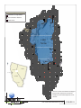
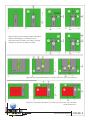
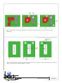
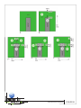
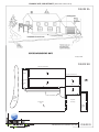
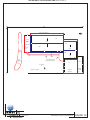
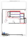
Load Reduction Planning Tool (LRPT) v 2 Technical and User Guidance Document CONTENTS List of Figures.............................................................................................................................................................. i List of Tables .............................................................................................................................................................. ii Executive Summary ....................................................................................................................................................... 1 1. Introduction ............................................................................................................................................................... 1 2. Key Terms .................................................................................................................................................................. 2 3. General Approach ...................................................................................................................................................... 4 4. Theory and Methodology .......................................................................................................................................... 4 5. LRPT User Guidance ................................................................................................................................................. 17 STEP 1. Specify Parcel Boundaries ........................................................................................................................... 18 STEP 2. Define Scenario and Site Condition ............................................................................................................ 18 STEP 3. Delineate Patch Boundaries and Hydrologic Linkages ................................................................................ 19 STEP 4. Assign Hydrologic Routing Contributions ................................................................................................... 24 STEP 5. Populate LRPT Input Tables and Run Simulation ........................................................................................ 26 STEP 6. Repeat STEPS 2‐5 for All Desired Scenarios ................................................................................................ 30 STEP 7. Compare Runoff and Pollutant Loads ......................................................................................................... 30 STEP 8. Generate LRPT Summary Report ................................................................................................................ 31 6. Programatic Integration........................................................................................................................................... 31 7. LRPT v2 Limitations and Next Steps ......................................................................................................................... 33 8. Acronyms and Glossary ........................................................................................................................................... 35 9. References ............................................................................................................................................................... 38 Appendix A. LRPT v2 Tutorial ....................................................................................................................................... 39 LIST OF FIGURES Figure 1 Simple schematic showing hydrologic routing between two patches .................................................5 Figure 2 Hydrologic routing between three patches ..........................................................................................7 Figure 3 Meteorological grids in Tahoe Basin ....................................................................................................8 Figure 4 Treatment BMP annual runoff coefficients ....................................................................................... 11 Figure 5 LRPT modeling of maintenance influence on BMP C values ............................................................. 13 Figure 6 Site delineation examples .................................................................................................................. 21 Figure 7 Site delineation examples ................................................................................................................. 23 Figure 8 Flow percentage examples ................................................................................................................ 25 Figure 9 Pre‐retrofit site schematic and map .................................................................................................. 49 Figure 10 Pre‐retrofit site patch delineation ..................................................................................................... 50 Figure 11 Pre‐retrofit site flow routing ............................................................................................................. 51 Final: November 2010 p. i