1
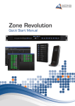
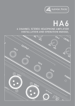
Australian Monitor
INSTALLATION
SERIES
Clever Features, Contractor Friendly
DigiPageJr
Multizone Paging
&
Program Selection
System
Installation
&
Operation
Manual
ZONE 1
ZONE 2
ZONE 3
ZONE 4
ZONE 5
ZONE 6
ZONE 7
ZONE 8
PAGE ENABLE
PROG 1
TREBLE
PROG 1
TREBLE
PROG 1
TREBLE
PROG 1
TREBLE
PROG 1
TREBLE
PROG 1
TREBLE
PROG 1
TREBLE
PROG 1
TREBLE
ZONE 1
ZONE 5
PROG 2
BASS
PROG 2
BASS
PROG 2
BASS
PROG 2
BASS
PROG 2
BASS
PROG 2
BASS
PROG 2
BASS
PROG 2
BASS
ZONE 2
ZONE 6
PROG 3
PROG
PROG 3
PROG
PROG 3
PROG
PROG 3
PROG
PROG 3
PROG
PROG 3
PROG
PROG 3
PROG
PROG 3
PROG
ZONE 3
ZONE 7
MIC
PROG 4
MIC
PROG 4
MIC
PROG 4
MIC
PROG 4
MIC
PROG 4
MIC
PROG 4
MIC
PROG 4
MIC
ZONE 4
ZONE 8
ON
POWER
PROG 4
4
5
4
6
3
8
1
9
0
10
MASTER 1
5
4
6
3
7
2
8
1
9
0
10
MASTER 2
5
4
6
3
7
2
8
1
9
0
10
MASTER 3
5
4
6
3
7
2
8
1
9
0
10
MASTER 4
5
4
6
3
7
2
8
1
9
0
10
MASTER 5
5
4
6
3
7
2
8
1
9
0
10
MASTER 6
5
4
6
3
7
2
8
1
9
0
10
MASTER 7
5
6
3
7
2
7
2
8
1
9
0
10
MASTER 8
Australian Monitor
INSTALLATION SERIES
Internal Revision Info
Rev 1 25/06/03
Rev 2 09/10/03
Rev 3 05/11/03
Rev 4 06/11/03
Rev 5 20/11/03
AUS, EUR, USA
Copyright 20th Nov 2003
Rev A: 20th Nov 2003
This symbol is intended to alert the user to the
presence of uninsulated “dangerous voltage”
within the product’s enclosure that may be of
sufficient magnitude to constitute a risk of electric
shock to persons.
CAUTION
RISK OF ELECTRIC SHOCK
DO NOT OPEN
CAUTION: TO REDUCE THE RISK OF ELECTRIC SHOCK.
This symbol is intended to alert the user to the
presence of important operation and maintenance (servicing) instructions in the literature
accompanying the appliance.
DO NOT REMOVE COVER (OR BACK).
NO USER-SERVICEABLE PARTS INSIDE.
REFER SERVICING TO QUALIFIED SERVICE PERSONNEL.
WARNING !
To prevent electric shock do not use this (polarized) plug
with an extension cord, receptacle or other outlet unless
the blades can be fully inserted to prevent blade exposure.
TO REDUCE THE RISK OF FIRE OR ELECTRIC SHOCK.
DO NOT EXPOSE THIS EQUIPMENT TO RAIN OR MOISTURE.
To prevent electric shock, match wide blade of plug to
wide slot, fully insert.
Caution:
Australian Monitor
INSTALLATION SERIES
2
CONTENTS
1. Introduction
Page
4
2. Front Panel
5
3. Back Panel
8
4. Installation
11
5. Setup
14
6. Linking Two DigiPageJr Systems
16
7. Paging Station
18
8. Accessories
20
9. Troubleshooting Guide
20
10. Block Diagram
21
11. Dimensions
22
12. Specifications
23
Australian Monitor
3
INSTALLATION SERIES
1. INTRODUCTION
The Australian Monitor Installation Series DigiPageJr is a two rack unit multizone paging and
source selection system that offers unprecedented flexibility for multizone paging & source
routing applications. Four program inputs are available to each of eight zone outputs. The
DigiPageJr is also expandable to 16 zones via a simple link cable to a second unit. Paging
stations are available in 8 zone and 16 Zone models allowing paging into any individual
zone, any combination of zones or All Call. There is also the ability to have one Paging Station
as a priority paging station. The Paging stations connect via an inexpensive and industry
standard CAT5 cable network. An overall priority input is also provided for emergency or
evacuation signals. The DigiPageJr is powered by an (included) external plug-pack power
supply or via 24VDC. The DigiPageJr is a versatile and well featured product that provides a
simple solution to the complex applications of multizone paging and source routing.
We thank you for choosing Australian Monitor Installation Series and as with all our products,
the DigiPageJr offers clever features and is contractor friendly.
Australian Monitor
INSTALLATION SERIES
4
2. FRONT PANEL
ZONE 1
ZONE 2
ZONE 3
ZONE 4
ZONE 5
ZONE 6
ZONE 7
ZONE 8
PAGE ENABLE
PROG 1
TREBLE
PROG 1
TREBLE
PROG 1
TREBLE
PROG 1
TREBLE
PROG 1
TREBLE
PROG 1
TREBLE
PROG 1
TREBLE
PROG 1
TREBLE
ZONE 1
ZONE 5
PROG 2
BASS
PROG 2
BASS
PROG 2
BASS
PROG 2
BASS
PROG 2
BASS
PROG 2
BASS
PROG 2
BASS
PROG 2
BASS
ZONE 2
ZONE 6
PROG 3
PROG
PROG 3
PROG
PROG 3
PROG
PROG 3
PROG
PROG 3
PROG
PROG 3
PROG
PROG 3
PROG
PROG 3
PROG
ZONE 3
ZONE 7
MIC
PROG 4
MIC
PROG 4
MIC
PROG 4
MIC
PROG 4
MIC
PROG 4
MIC
PROG 4
MIC
PROG 4
MIC
ZONE 4
ZONE 8
ON
POWER
PROG 4
4
5
4
6
3
8
1
9
0
10
MASTER 1
5
4
6
3
7
2
8
1
9
0
5
10
MASTER 2
4
6
3
7
2
8
1
9
0
10
MASTER 3
5
4
6
3
7
2
8
1
9
0
5
10
MASTER 4
4
6
3
7
2
8
1
9
0
10
MASTER 5
5
4
6
3
7
2
8
1
9
0
10
MASTER 6
Expanded view
5
4
6
3
7
2
8
1
9
0
10
MASTER 7
5
6
3
7
2
7
2
8
1
Australian Monitor
9
0
INSTALLATION SERIES
10
MASTER 8
7
8
9
3
4
1
5
6
2
Australian Monitor
5
INSTALLATION SERIES
The controls detailed below (1-6) apply to each output zone, as indicated by
ZONE 1 .. ZONE 8 on the front panel.
1 PROG 1-4:
This series of program switches (PROG 1- PROG 4) allows any one of the connected
program sources to be switched to this zone. Note that these are mechanically
interlocking switches: only one program may be selected at a time. Program inputs may
be mic or line, see Back Panel on page 8.
2 MASTER 1-8:
This control adjusts the overall output level of the zone.
3 TREBLE
The treble control has 10dB of cut or boost at 10kHz. The treble control affects the entire
zone.
NOTE:
Note that ‘center’ is to the right (3 o’clock), not the top (12 o’clock).
4 BASS
The bass control has 12dB of cut or boost at 100Hz. The bass control affects the entire
zone.
NOTE:
Note that ‘center’ is to the right (3 o’clock), not the top (12 o’clock).
5 PROG
This control adjusts the overall level of the selected program source into the zone.
NOTE:
To balance the differing levels of each program input, the program trim
controls on the Back Panel should be used (see Back Panel and Setup
sections)
6 PAGE
This control adjusts the paging mic level into the zone.
Australian Monitor
INSTALLATION SERIES
6
Located at the right-hand end of the unit, these controls affect all zones.
7 PAGE ENABLE
This switch allows the zone to be included in or isolated from the paging function. You may
want to do this when a zone is an area such as a function room that occasionally may
need to be isolated from paging.
8 ON
This LED indicates there is power to the unit.
NOTE:
When 24VDC emergency power is supplied this LED will always be on.
9 POWER
This switches power from the power supply (included ).
NOTE:
When 24VDC emergency power is supplied, the unit is on regardless of
the switch position.
Australian Monitor
7
INSTALLATION SERIES
3. BACK PANEL
1
5
8
PROG 4
ENGINEERED BY AUDIO TELEX COMMUNICATIONS PTY LTD SYDNEY AUSTRALIA
POWER IN
VDC
PROG 3
PROG 2
PROG 1
PROG LINKS
PROG
GAIN
OUTPUT
+24V
INPUT
MIC
PROG
GAIN
LINE
PROG
GAIN
MIC
LINE
MIC
PROG
GAIN
LINE
LINE
MIC
TONE GEN
OUTPUT
LEVEL
SUM IN
CAT 5
RUN 1
GROUND
CAT 5
RUN 2
EVAC
CAT 5
RUN 3
ALERT
CAT 5
RUN 4
COMMON
DATA LINK
SLAVE
GROUND
MASTER
+ 24V DC
ZONE OUTPUTS
SUM
INPUT
LEVEL
8
7 6
4a
4b
7
6
5
4
3
3
2
1
2
1 PROG 1 - 6 Input Section
LINE
The pair of RCA sockets accepts unbalanced line level inputs.
Stereo signals are internally summed to mono.
MIC
The XLR socket accepts balanced microphone level signals.
PIN 2
HOT
+
PIN 1
GND
PIN 3
COLD
-
PROG GAIN
The trimpot controls the input gain of BOTH the balanced and
unbalanced program inputs. In a Master/Slave configuration,
these also control program linked inputs. (see Linking Section)
FEMALE XLR
2 ZONE OUTPUTS
There is a balanced XLR line level output for each zone.
PIN 2
HOT
+
PIN 1
GND
PIN 3
COLD
MALE XLR
NOTE:
If connecting to an unbalanced input, the negative pin (3) should not be
connected to ground but left floating.
NOTE:
When operating as a slave unit, outputs labelled 1 to 8 will correspond to
zones 9 to 16, respectively. (see Linking Section)
Australian Monitor
INSTALLATION SERIES
8
3 EUROBLOCK CONNECTOR
24V DC / GROUND
This input pair is for connection to a 24VDC
emergency power supply and is not switched by
the front panel power switch.
NOTE: The 24V DC input does not provide a
trickle-charge facility.
ALERT/EVAC/COMMON
These connections are used to trigger the
internal tones. Only one tone can be triggered
at a time. Triggering occurs by connecting the
ALERT or EVAC terminal to COMMON.
GROUND/SUM IN
This is an unbalanced line level input which may
be used for emergency priority signals. It feeds
all zone outputs independent of output level
settings and page enable status.
NOTE: Signal on the SUM IN will cause other signals
to be muted.
NOTE: The muting by the SUM IN remains active
for 30sec after the input signal is removed.
SUM INPUT LEVEL
This recessed trimpot sets the level of the sum input.
TONE GEN OUTPUT LEVEL
This recessed trim pot controls the output level of the
tones and the pre-annouce chime.
4a CAT 5 RUN 1
This RJ45 input accepts the CAT5 cable coming from the priority paging microphone
station. See ‘Installation’ on page 12 for more information. If you would like to have a
paging station set as a priority over all other paging stations, then it must be connected to
this RJ45 socket and no other stations may use this connector or the run that it is on. The
paging station also needs to be set up as a priority station (see Paging Station section).
4b CAT 5 RUN 2-4
These RJ45 inputs accept the CAT5 cables coming from the Paging Stations. See page
12 for more information.
NOTE:
These are NOT Ethernet connections.
NOTE:
Connecting and disconnecting these inputs while the unit is on may
cause the unit to lock up requiring system power to be cycled.
Australian Monitor
9
INSTALLATION SERIES
5 PROG LINKS
These RJ45 sockets allow linking of the program sources when using a Master/Slave
configuration. (see ‘Linking Section’ on page 18)
NOTE:
These are NOT Ethernet connections.
6 DATA LINK
This socket is used to link two units in a Master/Slave configuration. (see ‘Linking Section’ on
page 18)
NOTE:
These are NOT Ethernet connections.
7 MASTER/SLAVE
This switch is used when linking 2 units in Master/Slave configuration. (see ‘Linking Section’
on page 18)
8 POWER IN VAC
This 2.1mm power socket accepts the 20VAC power supply provided with the unit.
Australian Monitor
INSTALLATION SERIES
10
4. INSTALLATION
OVERVIEW
The DigiPageJr features extensive flexibility in the range of input sources that it can
accommodate. In addition, the zone outputs may be used to feed power (booster)
amplifiers, mixers, mixer amplifiers etc. It is therefore important to think about the interfacing
of the DigiPageJr with the other equipment if optimum performance and system stability is to
be achieved. Use the Back Panel and Specifications sections of this manual to assist with
system design.
NOTE: XLR CONFIGURATION
PIN 2
HOT
+
PIN 1
GND
PIN 2
HOT
+
PIN 1
GND
PIN 3
COLD
-
PIN 3
COLD
FEMALE XLR
MALE XLR
When wiring the outputs on the DigiPageJr as
unbalanced, Pin2 should be used as hot and Pin1
as ground. Pin3 should be left open and NOT
shorted to Pin1.
NOTE: If installing and terminating CAT5 cable is new to you, please take note of the
various points that follow. As the CAT5 cabling for the DigiPageJr carries voltage,
damage could occur if your pin-pin connections are not made correctly.
CABLE INSTALLATION FOR PAGING STATIONS
Four RJ45 ports (labelled CAT 5 RUN 1-4) are provided for connection to the DigiPageJr Zone
Paging Stations. The four ports allow for easy cable infrastructure, as CAT5 runs can be of
differing lengths depending on the installation and the number of paging stations
connected.
In planning the installation, the following rules apply:
Up to 4 Paging Stations may be connected to each of the four CAT5 runs.
Connections along the runs must be in a daisy-chain configuration. It is acceptable to
create a short branch (eg, from a wall outlet to a paging station). The maximum
length of the branch is 10m.
The following table indicates the maximum distance allowable for a CAT5 run on a
single port.
For greater distances or more paging stations, see page 14.
The last unit on a run must be terminated. This is done by moving a jumper on the
paging station or remote unit. See ‘Paging Station’ on page 18 or ‘Remote Control
Panel’ on page 21.
NUMBER OF DEVICES
ON SINGLE CAT5 RUN
MAX DISTANCE
TO END UNIT (m/ft)
1xPaging Station
2xPaging Staions
3xPaging Stations
4xPaging Stations
250m/820ft
125m/410ft
80m/260ft
62.5m/205ft
TABLE #1
Australian Monitor
11
INSTALLATION SERIES
INSTALLATION OF A PRIORITY PAGING STATION
The following rules apply for connecting a paging station as a priority paging station to over
ride all other paging stations:
The paging station must be enabled as a priority paging station (see Paging Station
section on page 20).
The paging station that is used as a priority station must be connected to CAT5 RUN 1.
The only paging station that can be connected to CAT5 RUN 1 is the priority paging
station. No other paging stations may share that CAT5 RUN.
NOTE:
These are NOT Ethernet connections.
CAT5 CABLE
CAT5 cable is the blue cable commonly used for data installations (other colours do exist). It
consists of four twisted pairs of wires: this is why it is often referred to as UTP (Unshielded Twisted
Pair). The most readily available cable uses solid conductors, like telephone wire. Cable with
stranded conductors is available, and is more flexible.
CAT5 TERMINATION
Pre-wired CAT5 cable comes in two configuration standards, 568A and 568B. It is advisable to
carry a good pre-wired cable for fault-finding. Both configurations will work with the
DigiPageJr provided both ends have the same configuration. Be careful not to use a
crossover cable which has one configuration at one end and the other configuration at the
other end.
Ensure that the RJ45 connectors are suited to the cable used (solid or stranded) and that the
correct crimp tool is used.
When wiring connectors, 568A standard wiring is recommended (see diagram).
Shown with
locking clip
facing
White/Green 1
Green 2
White/Orange 3
Blue 4
White/Blue 5
Orange 6
White/Brown 7
Brown 8
CABLE
Ground
Power
Ground
BusyBusy+
Priority
Data/Voice+
Data/Voice-
568A configuration
NOTE: CAT5 cable consists of four pairs of wires: it is not sufficient to simply wire the two
ends pin for pin, ignoring pairing.
POWER REQUIREMENTS
The DigiPageJr can operate from the plug pack supplied and/or a separate 24V DC power
supply.
A NOTE ABOUT GROUNDING:
It may be necessary in some circumstances to ground the DigiPageJr to eliminate
noise in the system. This can be done using the negative terminal of the 24VDC IN
euro connector or by making sure that the chassis is electrically connected to the
equipment rack (which should be grounded).
Australian Monitor
INSTALLATION SERIES
12
EXTENDING CAT5 CABLE RUN DISTANCES & ADDING MORE PAGING STATIONS
The maximum distances quoted in the Table #1 are due to DC current limitations, not data
transmission limitions. If distances greater than these are required, the paging stations can
be locally powered. This will extend the maximum distances to 1000m per CAT5 RUN.
Alternatively, if more than 4 paging stations are required on a single run, local powering can
be used. This will increase the maximum number of paging stations on a single CAT5 RUN.
Use a regulated 12VDC supply connected as
pin1 (white/green in CAT5)- GROUND
pin2 (green in CAT5) - +12V
Disconnect incoming +V, but not ground. The 12V supply should be rated at 150mA per
microphone being powered. For further information email [email protected].
TONE GENERATOR INPUTS
Tones may be triggered by closing a switch or relay contact between the selected tone
trigger input and common. These trigger inputs are 5V TTL and may alternatively be triggered
by pulling the desired input low referenced to the COMMON.
NOTE: The maximum voltage on these inputs must not exceed 5.5V
PRE-ANNOUNCE CHIME
The only internal setup that is available in the DigiPageJr is for the configuration of the chime
tone that sounds in each zone. The unit comes shipped with the chime enabled in all zones.
A link can be found on the main board just behind the zone control boards (see diagram).
To disable the chime to a particular zone, remove the link. To re-enable the chime, replace
the link.
NOTE: Remember to wait for the chime to finish before speaking. Note that when
the chime is disable it will still activate but will not be heard so you must still
wait approximately 1 sec before speaking after press the page button.
Zone 1
Zone 2
Zone 3
Zone 4
Zone 5
Zone 6
Zone 7
Zone 8
Australian Monitor
13
INSTALLATION SERIES
5. SET UP
The inputs of the DigiPageJr can accommodate a wide range of sources including active
paging stations, dynamic microphones, DVD and CD players, tuners and cassette players.
The zone outputs may be used to drive power (booster) amplifiers, mixers, or mixer amplifiers.
Each installation will require setting the appropriate relative mix of levels between paging
and program sources for each zone and balancing between the zones.
Because of the variation in levels between the possible sources, DigiPageJr offers a number
of gain stage adjustment so you can set the correct levels for your application.
Also consider what the outputs are driving.
Setting up correct gain structure through the whole system is important to achieve optimal
results.
The following step by step procedure has been devised to assist during the setup process.
When the DigiPageJr was shipped to you from the factory it was set up in a particular way. In
the following procedure it is essential that you are starting from these initial settings.
Program Input Gain Controls - half (12 o’clock)
Master Volume - off
Mic level - half (3 o’clock)
12 o’clock 3 o’clock
Prog level - half (3 o’clock)
Step by step setup
Confirm the initial settings of DigiPageJr.
Choose a zone that is conveniently located near to the DigiPageJr or further away if you feel
you need the exercise.
This will be the referred to as “TEST ZONE”.
Ensure that all amplifiers connected to the DigiPageJr are set to provide required sound levels
with a line level input signal.
Choose a consistent program source, eg CD or tuner.
This will be the referred to as “TEST PROG”.
1. Select TEST PROG in the TEST ZONE [front PROG 1-4].
Set the MASTER volume in the TEST ZONE to half way.
2. Adjust the rear PROG GAIN for the TEST PROG input to achieve the required sound level
in the TEST ZONE.
3. Select PROG TEST in all other zones.
4. Bring up the MASTER volume in all other zones and check for required sound levels.
5. Make a test page to the TEST ZONE and check the level relative to the program level.
6. Adjust the page level as desired [front panel PAGE].
Australian Monitor
INSTALLATION SERIES
14
7. Balance the other program sources in the TEST ZONE [rear panel PROG GAIN]
8. Apply the front panel settings from TEST ZONE to all other zones.
9. Using the front panel controls only, set the individual zones to your preferred settings
a. Set balance between prog/page
b. Set Eq
c. Set final master level
NOTE: A full discussion of setting up a complex system with correct gain structure is
beyond the scope of this manual. The procedure above assumes that the
installer has correctly set up external equipment connected to DigipageJr
prior to initiating the set up procedure.
Australian Monitor
15
INSTALLATION SERIES
6. LINKING TWO DIGIPAGEJr SYSTEMS
NOTE: There are two series of DigiPage product available, the DigiPage and the
DigiPageJr. Use only DigiPageJr series paging stations with DigiPageJr and
only DigiPage series paging stations with DigiPage.
DigiPageJr is fully expandable to form a 16 zone paging system by the simple linking of two
units. One DigiPageJr is then designated the master unit, driving zones 1-8, with the other
slave unit driving zones 9-16. The following settings and connections are required to form a
linked DigiPageJr system.
The DigiPageJrM16 paging station must be used to access all zones. The DigiPageJrM8 can
also be used but will only access zones 1 to 8
White/Green 1
Green 2
White/Orange 3
Blue 4
White/Blue 5
Orange 6
White/Brown 7
Brown 8
PROG 1
PROG 2
PROG 3
PROG 4
NC
NC
GROUND
GROUND
CABLE
568A configuration
Program Source Wiring
MASTER/SLAVE
This switches the unit from master (switch in) to slave (switch out). When set as master the unit
control zones 1 to 8. When set as slave the unit controls zones 9 to 16. This switch should only
be operated when the unit is powered off.
DATA LINK
This link is essential. Use a pre-wired CAT5 patch lead.
The maximum cable length for the data link cable is 10m, but note that the PROG LINKS
cable length is limited to 0.5m (see below).
NOTE: Maximum data link cable length is 10m
NOTE:
These are NOT Ethernet connections.
Australian Monitor
INSTALLATION SERIES
16
PROG LINKS
Program sources can be sent to the slave DigiPageJr by connecting the PROG LINKS OUTPUT
on the Master unit to the PROG LINKS INPUT on the Slave unit. This simplifies connection of
sources as all 4 sources can be sent from the master to the slave via 1 CAT5 cable avoiding
the need for Y-cables
The PROG TRIM on the slave unit operates independently of the master unit. The PROG TRIM
on the slave unit should be set to the same position as on the master.
Use a pre-wired CAT5 patch lead. The maximum cable length for the program source link
cable is 0.5m. However this cable should be kept as short as possible because it is carrying
audio signal.
NOTE: If PROG LINKS is not used, it is possible to use completely different program
sources in zones 1-8 to zones 9-16.
NOTE: Maximum prog link cable length is 0.5m
PRIORITY PAGING STATION
If a priority paging station is being used in a linked 16 zone system it must be connected to
CAT5 RUN 1 of the master unit.
Australian Monitor
17
INSTALLATION SERIES
7. PAGING STATION
Introduction
DigiPageM8
DigiPageM16
The Australian Monitor Installation Series DigiPageJrM8 and DigiPageJrM16 Paging Stations
are 8 and 16 zone paging stations complete with a slimline gooseneck paging microphone.
The Paging stations are designed to be used with the DigiPageJr Zone Paging & Source
Selection System and will allow paging into any individual zone, any combination of zones or
All Call to all zones. LED indicators provide the user with visual feedback of the zones being
paged or if the sytem is busy. Label space is provided on the Paging Station, which also
provides a microphone gain control. Connection to the DigiPageJr is via low cost CAT 5
cable and as with all Australian Monitor installation products, the Paging Station provides an
elegant solution at a contractor friendly price.
1 ZONE select
These buttons allow selection of zones for paging.
When selected, the adjacent LED glows green.
Pressing the button again deselects the zone. The area
next to the button is for labelling the zone. Selecting a
zone does not instigate paging. See 4. ZONE PAGE.
Controls
115.0mm
Australian Monitor
INSTALLATION SERIES
178.0mm
BUSY
CLEAR
5
2
ALL PAGE
3
ZONE PAGE
4
2. CLEAR
This button clears all the selected zones.
3. ALL PAGE
This button pages to all zones. It is momentary so must
be held while talking into the microphone. It activates
the microphone and mutes the program sources. It
does NOT clear the current zone selection
configuration so the paging station will return to its
previous state (selected zones) once the ALL PAGE
button is released.
NOTE: Remeber to wait 1 sec for the pre-announce chime to finish.
4. ZONE PAGE
This button pages to the current zone selection
configuration as indicated by the ZONE select LEDs
see 1 above. The zones being paged have their
program sources muted and the microphone
becomes active. If no zones are selected the system
will still show as busy when this button is pressed.
1
Base Plate
section
6
Australian Monitor
INSTALLATION SERIES
NOTE: Remeber to wait 1 sec for the pre-announce chime to finish.
5. BUSY
This LED glows when the network or system is busy. This
can be caused by the local paging station (you are
making a page) or by another paging station. Paging
is not possible while the system is busy, however zone
selections can still be made.
18
Installation and Setup
NOTE: There are two series of DigiPage product available, the DigiPage and the
DigiPageJr. Use only DigiPageJr series paging stations with DigiPageJr and
only DigiPage series paging stations with DigiPage.
The CAT5 cable connects to the RJ45 socket on the rear panel of the paging station. This
socket is a NEUTRIKTM connector designed to be used with the XLR style housing (model
NE8MC) to improve reliability. Normal RJ45 connectors can also be used.
Plugging and unplugging the cable while the system is powered up may result in the system
locking up and is not recommended. If this should happen, reset the DigiPageJr by switching
off, then on.
6 GAIN
To accommodate different speech levels, there is a gain control on the base of the
DigiPageJrM. This ships set to minimum and may be adjusted to suit. Increasing this
control too far may cause the paging station to distort if loud or close speech levels are
encountered. Caution should be used if trying to achieve high gain levels for distant or
lectern speech styles as feedback may occur.
7 TERMINATING
In an RS485 network (of which the DigiPageJr is part of) it is important to terminate the last
device in the network CAT5 RUN. A jumper is provided for the data/voice transmission to
be terminated if that Paging Station is at the end of a CAT5 RUN (see diagram). Shipped as
unterminated.
8 PRIORITY
If a Paging station is being used as a priority over all other Paging Stations then the
following rules apply
The Priority Paging Station must be connected to CAT5 RUN 1
No other Paging station may be connected to CAT5 RUN 1
The Priority Paging Station must be set as priority by moving the jumper (see diagram).
Shipped no priority set.
NOTE: When making changes be sure to power off and disconnect .
Gain Pot
(accessible through base plate)
8
7
(shown with Priority Enabled)
Data/Voice
(shown as terminated)
Australian Monitor
19
INSTALLATION SERIES
8. ACCESSORIES
8 zone Paging Station
16 Zone Paging Station
Punch down tool
Black System Input Plate
White System Input Plate
Black Standoff surface mount Box
White Standoff surface mount box
Cat5 Cable tester
Cat No. DPJR8M
Cat No. DPJR16M
Cat No. DPPDT
Cat No. DPRIPB
Cat No. DPRIPW
Cat No. DPRMSMBB
Cat No. DPRMSMBW
Cat No. ATC-C5CT
NOTE: The paging stations for the DigiPageJr are different to the DigiPage and
cannot be mixed. The same applies to DPRM’s which cannot be used
with the DigiPageJr.
9. TROUBLESHOOTING GUIDE
Trouble
Remedy
Likely Cause
DigiPage System
No response to controls
Poor signal to noise ratio
Mains brownouts or incorrect
connection of devices may
cause processor to lock-up
Cycle power on the DigiPageJr
Incorrect system gain
structure
-Check settings of all equipment
-Revisit Step-by-Step Setup Procedure
Lack of system ground
See Grounding in Installation
section
Initailisation (boot) sequence
Normal operation when power
is applied
Cable too long
See Installation section
Cable fault
-Check cable.
-Check Paging Station with good cable at DigiPage
Paging Station
LED’s chase
Inconsistent operation
Terminate the paging station.
See Paging Station on page 20
Last station on run not
terminated
Emits high-pitch whine
With all Paging Stations connected,
Station lock-up due to
connection while system is live cycle power on the DigiPageJr
Australian Monitor
INSTALLATION SERIES
20
REPEATED
FOR
PROGRAMS 2 - 4
PROGRAM
P1
21
SUM INPUT
-43dB
-43dB
TONE
GEN
OUTPUT
ROUTING
LOGIC
PWM
DECODER
SUM INPUT
LEVEL
-20dB
+13.5dB
TONE/
CHIME
GEN
RS485
REC
VOICE
&
DATA
PROG LINK IN
+30dB
-33dB
P4
P3
P2
P1
PAGE
PROG
SIGNAL
DETECT
0dB
CHIME
-27dB
CHIME ENABLE
(internal)
ALERT/EVAC
-36dB
-6.5dB
OFF
OFF
MECHANICALLY
INTERLOCKING
+13.5dB
PROGRAM
SELECTION
SWITCHES
MICROPROCESSOR
EVAC
ALERT
COM
SLAVE
MASTER
DATA LINK
CAT5 RUN
2-4
CAT5 RUN 1
(priority)
MIC
LINE
PROG LINK OUT
+13.5dB
+6.5dB
+6.5dB
0dB
PAGE
ENABLE
CONTROL
EQ
1 OF 8 ZONES
ZONE2
ZONE3
ZONE4
ZONE5
ZONE6
ZONE7
ZONE8
ZONE1
+6dB
ZONE OUPUT
10. BLOCK DIARGRAM
Australian Monitor
INSTALLATION SERIES
11. DIMENSIONS
482.00 mm
466.00 mm
ZONE 3
ZONE 4
ZONE 5
ZONE 6
ZONE 7
ZONE 8
PAGE ENABLE
PROG 1
TREBLE
PROG 1
TREBLE
PROG 1
TREBLE
PROG 1
TREBLE
PROG 1
TREBLE
PROG 1
TREBLE
PROG 1
TREBLE
ZONE 1
ZONE 5
PROG 2
BASS
PROG 2
BASS
PROG 2
BASS
PROG 2
BASS
PROG 2
BASS
PROG 2
BASS
PROG 2
BASS
PROG 2
BASS
ZONE 2
ZONE 6
ON
POWER
PROG 3
PROG 4
4
5
PROG
PROG 3
MIC
PROG 4
4
6
3
PROG 4
MASTER 1
5
PROG
PROG 3
MIC
PROG 4
8
1
9
0
MASTER 2
5
PROG
PROG 3
MIC
PROG 4
10
MASTER 3
4
6
3
7
2
8
9
10
4
6
3
7
0
10
4
6
1
9
0
PROG 3
MIC
2
8
1
PROG
3
7
2
5
PROG 4
4
6
MASTER 4
PROG
PROG 3
MIC
PROG 4
MASTER 5
PROG
PROG 3
MIC
PROG 4
4
6
MASTER 6
ZONE 3
ZONE 7
MIC
ZONE 4
ZONE 8
6
7
8
1
9
0
PROG
2
8
1
10
5
3
7
2
8
9
0
5
3
7
1
10
4
6
2
8
9
0
10
5
3
7
1
9
0
PROG 3
MIC
2
8
1
PROG
3
7
2
5
MASTER 7
Australian Monitor
9
0
10
INSTALLATION SERIES
10
MASTER 8
444.00 mm
PROG 4
ENGINEERED BY AUDIO TELEX COMMUNICATIONS PTY LTD SYDNEY AUSTRALIA
POWER IN
VDC
PROG 3
PROG 2
PROG 1
PROG LINKS
PROG
GAIN
INPUT
OUTPUT
+24V
MIC
PROG
GAIN
LINE
PROG
GAIN
MIC
LINE
MIC
PROG
GAIN
LINE
LINE
MIC
OUTPUT
LEVEL
SUM IN
TONE GEN
SLAVE
GROUND
CAT 5
RUN 1
EVAC
CAT 5
RUN 2
ALERT
CAT 5
RUN 3
COMMON
MASTER
CAT 5
RUN 4
GROUND
ZONE OUTPUTS
DATA LINK
SUM
INPUT
LEVEL
7
6
5
4
3
187.50 mm
18.00 mm
6.00 mm
Australian Monitor
INSTALLATION SERIES
22
2
1
88.00 mm
ZONE 2
TREBLE
+ 24V DC
76.00 mm
ZONE 1
PROG 1
12 .SPECIFICATIONS
-Dimensions:
88.0 x 482.0 x 205.5 (HxWxD) mm
-Weight:
Net 4.5kg Shipping 5.5kg
Net 9.9lb Shipping 12.1lb
-Power Input:
20VAC
30VA max
-Program Sources:
(trim max)
Unbalanced (RCA)
Input Impedance:100kohm
Sensitivity: 150mV (-14dBu)
Balanced (XLR)
Input Impedance: 1k3ohm
Sensitivity: 1mV (-57dBu)
Min Trim: -46dB
-Sum Input:
Input Sensitivity: 160mV (-13.5dBu)
Threshold: -46dBu (at output, ind of input)
-Frequency Response:
(0dB/-3dB)
15Hz - 17kHz
-THD:
0.005%
-Noise:
Page Mic: -84dB
Other Inputs: -89dB
All measurements are reference to 1.5V (+6dBu)
Australian Monitor
23
INSTALLATION SERIES
AUSTRALIA and NEW ZEALAND
www.australianmonitor.com.au
Sydney
(NSW & ACT Sales)
Brisbane
(Qld Sales)
Perth
(WA Sales)
Private Bag 149, Silverwater NSW 1811
149 Beaconsfield Street, Silverwater NSW 2128
Ph: (02) 9647 1411
Fax: (02) 9648 3698
E-mail: [email protected]
P.O. Box 871, Fortitude Valley QLD 4006
42 Commerical Road, Fortitude Valley QLD 4006
Ph: (07) 3852 1312
Fax: (07) 3252 1237
E-mail: [email protected]
P.O. Box 404, North Perth WA 6906
299 Fitzgerald Street, West Perth WA 6005
Ph: (08) 9228 4222
Fax: (08) 9228 4233
E-mail: [email protected]
Melbourne
(Vic & Tas Sales)
Adelaide
(SA & NT Sales)
Auckland
(NZ Sales)
P.O. Box 151, Blackburn South VIC 3130
22/277 Middleborough Road, Box Hill VIC 3128
Ph: (03) 9890 7477
Fax: (03) 9890 7977
E-mail: [email protected]
P.O. Box 157, Hindmarsh SA 5001
31 Walsh Street, Thebarton SA 5031
Ph: (08) 8352 4444
Fax: (08) 8352 4488
E-mail: [email protected]
P.O. Box 512, Albany 1331
Unit B, 11 Piermark Drive, Albany 1331
Ph: (09) 415 9426
Fax: (09) 415 9894
E-mail: [email protected]
EUROPE/ASIA/MIDDLE EAST
www.australianmonitor.com.au
International Sales
Private Bag 149, Silverwater NSW 1811
149 Beaconsfield Street, Silverwater NSW 2128
Australia
Ph: 61-2- 9647 1411
Fax: 61-2-9748 2537
E-mail: [email protected]
USA/CANADA/SOUTH AMERICA
www.australianmonitor.com
Australian Monitor Audio Inc.
PO Box 3126, Lynnwood, WA 98046
Ph: 425 673 5175
Fax: 425 673 7825
E-mail: [email protected]
PROG 4
ENGINEERED BY AUDIO TELEX COMMUNICATIONS PTY LTD SYDNEY AUSTRALIA
POWER IN
VDC
PROG 3
PROG 2
PROG 1
PROG LINKS
PROG
GAIN
OUTPUT
+24V
INPUT
MIC
PROG
GAIN
LINE
PROG
GAIN
MIC
LINE
MIC
PROG
GAIN
LINE
LINE
MIC
LEVEL
SUM IN
GROUND
OUTPUT
EVAC
TONE GEN
ALERT
DATA LINK
CAT 5
RUN 1
COMMON
SLAVE
CAT 5
RUN 2
GROUND
MASTER
CAT 5
RUN 3
+ 24V DC
ZONE OUTPUTS
CAT 5
RUN 4
SUM
INPUT
LEVEL
8
7
6
5
4
3
2
1