1
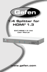
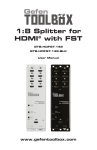
USER MANUAL
Check our knowledge base at
http://support.paralinx.net
TABLE OF CONTENTS
PARALINX TOMAHAWK
3
04
IMPORTANT NOTICE
05
SAFETY INSTRUCTIONS
06
OVERVIEW
07
QUICK START GUIDE
08
PACKAGE CONTENTS
09
REMOTE CONTROL
10
TRANSMITTER
12
RECEIVER
14
TRANSMITTER LED STATUS
15
RECEIVER LED STATUS
16
SLIDE & DIP SWITCHES
17
TOMAHAWK LINK MODES
18
LINKING A TRANSMITTER TO A SINGLE RECEIVER
19
LINKING A TRANSMITTER TO MULTIPLE RECEIVERS
4
IMPORTANT
NOTICE
IMPORTANT NOTICE
PARALINX TOMAHAWK
Paralinx reserves the right to make corrections, modifications, enhancements, improvements, and other
changes to its products and services at any time and
to discontinue any product or service without notice.
Customers should obtain the latest relevant information before placing orders and should verify that such
information is current and complete. All products are
sold subject to Paralinx’s terms and conditions of sale
supplied at the time of order acknowledgment.
Paralinx warrants performance of its hardware
products to the specifications applicable at the time of
sale in accordance with Paralinx’s standard warranty.
Testing and other quality control techniques are used
to the extent Paralinx deems necessary to support
this warranty. Except where mandated by government
requirements, testing of all parameters of each product is not necessarily performed.
to any combination, machine, or process in which
Paralinx products or services are used. Information published by Paralinx regarding third-party
products or services does not constitute a license
from Paralinx to use such products or services or a
warranty or endorsement thereof. Use of such information may require a license from a third party under
the patents or other intellectual property of the third
party, or a license from Paralinx under the patents or
other intellectual property of Paralinx.
Reproduction of information in Paralinx data books
or data sheets is permissible only if reproduction is
without alteration and is accompanied by all associated warranties, conditions, limitations, and notices.
Reproduction of this information with alteration is an
unfair and deceptive business practice. Paralinx is not
responsible or liable for such altered documentation.
Paralinx assumes no liability for applications assistance or customer product design. Customers are
responsible for their products and applications using
Paralinx components. To minimize the risks associated with customer products and applications, customers should provide adequate design and operating
safeguards.
Resale of Paralinx products or services with statements different from or beyond the parameters
stated by Paralinx for that product or service voids all
express and any implied warranties for the associated
Paralinx product or service and is an unfair and deceptive business practice. Paralinx is not responsible
or liable for any such statements.
Paralinx does not warrant or represent that any
license, either express or implied, is granted under
any Paralinx patent right, copyright, mask work right,
or other Paralinx intellectual property right relating
All company and brand products and service names
are trademarks or registered trademarks of their
respective holders.
SAFETY INSTRUCTIONS
SAFETY
INSTRUCTIONS
When operating this equipment, read and follow all
the instructions in this manual.
Do not block the air ventilation openings.
Keep these instructions in a safe and accessible
place for future reference.
Do not expose this equipment to water.
Clean only with a dry cloth.
Do not install near any heat sources such as radiators, heat registers, stoves, or other apparatus
(including amplifiers) that produce heat.
Use only accessories specified or recommended.
Do not defeat the grounding-type plug. A polarized
plug has two blades with one wider than the other.
A grounding-type plug has two blades and a third
grounding prong. The wide blade or the third prong is
provided for your safety. If the provided plug does not
fit into your outlet, consult an electrician for replacement of your obsolete outlet. Caution! To reduce the
risk of electrical shock, grounding of the center pin
of this plug must be maintained.
PARALINX TOMAHAWK
5
Protect the power cord from being walked on or
pinched particularly at the plugs, and the point
where they exit from the device.
Unplug this apparatus during lightning storms or
when unused for long periods of time.
Caution! Shock Hazard. Do not open the enclosure.
Refer to Paralinx for repair assistance.
Servicing is required when the device has been damaged in any way, such as power-supply cord or plug
is damaged, liquid has been spilled, or dirt/objects
have fallen into the apparatus, the apparatus has
been exposed to rain or moisture, does not operate
normally, or has been dropped.
6
OVERVIEW
OVERVIEW
PARALINX TOMAHAWK
The Paralinx Tomahawk is the world’s first light-weight
uncompressed ultra-long-range HD wireless system, capable
of sending ultra-low-latency full HD video with a range of up to
600m / 2000 feet
POWER INPUT WARNING!
The Tomahawk system accepts 7-17 volts DC maximum input
current! Subjecting the system to higher voltage will result in
damage or destruction and is not covered by warranty!
QUICK START GUIDE
QUICK START
GUIDE
TRANSMITTER
IMPORTANT NOTES
DISCONNECT VIDEO SOURCE
WHEN POWER CYCLING
SYSTEM
RECEIVER MUST BE POWERCYCLED IF TRANSMITTER IS
POWERED DOWN
RECEIVER
PARALINX TOMAHAWK
1
Disconnect video source from the transmitter.
2
Connect your Paralinx Tomahawk to a 12 V power source via
the Lemo input.
3
Connect the Tomahawk transmitter to the video source using
an HDMI cable.
4
It is recommended to set the dual antennas in the form of
a “V” and maintain unobstructed line of sight between transmitter
and receiver.
5
Connect your Tomahawk Receiver to a monitor using an
HD-SDI cable.
6
Connect your Tomahawk Receiver to a 12 V power source using the
Lemo input, or integrated battery plate.
7
Antennas should be arranged in the form of an open hand.
NOTES
For maximum range
• Keep line of sight between the transmitter and the
receiver.
• Maintain proper air ventilation for transmitter and
receiver.
*Note that high-output
wireless systems (F.P.V.,
radio control systems etc.)
can interfere with the
Tomahawk and reduce the
overall range.
• Avoid placing any obstacles between transmitter or
the receiver.
• If signal is lost bring the transmitter and receiver
closer together.
• Position both transmitter and receiver in an upright
position, for enhanced antenna performance.
• If using multiple receivers, keep a minimum of 6 feet
between receivers.
7
8
PACKAGE
CONTENTS
PACKAGE CONTENTS
PARALINX TOMAHAWK
1x HD wireless
video transmitter
1x 12 V Power supply
2x 5dBi Omni directional
antennas for Transmitter
1x HD-SDI wireless
video receiver
1x Remote Control
1x IR remote sensor
1x USB to
miniUSB cable
5x 2dBi Omniv directional
antennas for Receiver
REMOTE CONTROL
REMOTE
CONTROL
PARALINX TOMAHAWK
1 Enter main menu
6
Remove video source
2 Return to previous menu
7
Add new video source
3 Select video source
8
Powers receiver down
4 Operate for up, down
left and right directions on
the menu screen
9
Connect to 1st video source
5 Press OK to confirm
the operation
REMOTE
CONTROL
HOTKEYS
9
10 Connect to 2nd video source
11 Connect to 3rd video source
“ADD” hotkey
Direct access for starting the linking process on the receiver.
“Delete” hotkey
This hotkey button will open the “Remove Video Source” in the OSD
menu which allows the user to choose which device to remove.
Input Devices Key
Hotkey, “1, 2 or 3” will switch the receiver to link with the first, second
or third source registered to the receiver.
10
TRANSMITTER
TRANSMITTER
TRANSMITTER
SLIDE SWITCH
SETTINGS
PARALINX TOMAHAWK
1
Antenna Connectors
Dual RP-SMA
2
Connection status LED
Indicates the wireless network status
3
Video status LED
Indicates the video connection status
4
Low battery warning LED
Indicates input voltage is less than 7 V
5
Link button
For linking the transmitter to
additional receivers
6
Reset button
SINGLE-LINK MODE
S1
S2
7
Mini-USB Port
The USB port can be used for firmware
updates. *NOT A POWER INPUT
8
S1 Slide Switch
Left position: Single-link mode
Right position: Multi-link mode
9
S2
Not used
10
HDMI Input port
11
7-17 V LEMO power input connector
MULTI-LINK MODE
S1
S2
TRANSMITTER
PARALINX TOMAHAWK
1
9
8
2
4
3
5
6
10
11
7
11
12
RECEIVER
RECEIVER
DIP SWITCH
SETTINGS
RECEIVER
10
PARALINX TOMAHAWK
Antenna Connectors
5x RP-SMA - Type
16
Link Button
17
Input Voltage connector 7-17 V
11
Low battery warning LED
When input voltage is less than 7 V
18
ON/OFF Switch
12
Connection status LED
Indicates the wireless network state
19
IR input connector
20
HD-SDI output 1
13
Video status LED
indicates the video connection status
21
HD-SDI output 2
14
Diagnostic LED
22
Reset Button
23
15
Receiver DIP Switches
DIP switch # 1, 2, & 3 should be UP
DIP switch # 4 UP = Single-link mode
DOWN = Multi-link mode
Mini-USB for firmware updates
*NOT A POWER INPUT
SINGLE-LINK MODE
MULTI-LINK MODE
1
1
2
3
4
2
3
4
RECEIVER
PARALINX TOMAHAWK
10
20
17
22
11
21
20
13
12
14
15
20
21
16
18
23
19
13
14
TRANSMITTER
LED STATUS
TRANSMITTER LED STATUS
NETWORK LED CONNECTION
* YOUR PARALINX TOMAHAWK
PARALINX TOMAHAWK
Solid
Connection to Rx is established
Slow blinking
Transmitter is in listen mode
Normal blinking
During linking process
Fast blinking
(With Video LED)
System error; Cycle power
Solid
Video link established and locked in
Normal blinking
Video source is not supported
Fast blinking
(With Network LED)
System error
Solid
Low Battery; when input voltage is less then 7 V
TRANSMITTER FEATURES LEDS
WHICH WILL LIGHT UP TO INDI-
VIDEO CONNECTION LED
CATE SYSTEM STATUS.
LOW BATTERY WARNING LED
PARALINX TOMAHAWK
RECEIVER LED STATUS
RECEIVER LED
STATUS
NETWORK LED CONNECTION
* YOUR PARALINX TOMAHAWK
Solid
Connection to Tx is established
Slow blinking
Device is in listen mode
Normal blinking
During link setup mode
Fast blinking
(With Video LED)
System error, cycle power
Solid
Video link established and locked in
Fast blinking
(With Network LED)
Video source error
Solid
Receiver is powered up
RECEIVER FEATURES LEDS WHICH
WILL LIGHT UP TO INDICATE SYS-
VIDEO LED CONNECTION
TEM STATUS.
POWER LED
15
16
TRANSMITTER
SLIDE SWITCH
SLIDE/DIP SWITCHES
PARALINX TOMAHAWK
TOMAHAWK SWITCH POSITIONS
SINGLE-LINK MODE
S1
S2
MULTI-LINK MODE
S1
S2
RECEIVER
DIP SWITCH
SINGLE-LINK MODE
MULTI-LINK MODE
1
1
2
3
4
2
3
4
TOMAHAWK LINK MODES
TOMAHAWK
LINK MODES
PARALINX TOMAHAWK
17
The Paralinx Tomahawk supports the linking of multiple receivers to a single
transmitter as well as the linking of multiple transmitters to a single receiver.
The following guide illustrates different modes and options for linking transmitters and receivers:
Linking Tip:
Single-link mode enables DFS
(Dynamic Frequency Selection).
DFS allows the Tomahawk to
utilize more channels and to
automatically find the channel with the least amount of
interference.
The transmitter should be
kept no less than 3 feet and no
greater that 150 feet from the
receiver until DFS is activated
(60 seconds).
SINGLE-LINK MODE: Offers the best practice for operating a maximum number
of Tomahawk systems within the same enviroment, also allows for re-linking at
longer distances.
Transmitter slide switch
Receiver DIP switch
MULTI-LINK MODE: Allows the linking of up to four Tomahawk
receivers to a single transmitter. Linking can only be established within close
This will help the Tomahawk to proximity and DFS will be disabled.
better coexist with other wireless systems in the area.
NOTE: There will be a delay of
over 10 seconds when switching between Transmitters in
multi-link mode.
Transmitter slide switch
Receiver DIP switch
18
LINKING A TRANSMITTER TO A SINGLE RECEIVER
LINKING A
TRANSMITTER
TO A SINGLE
RECEIVER
NOTE: Before linking, both Transmitter and Receiver must be set to
Single-Link Mode.
(see page 15)
If there is no transmitter
registered to the receiver, you
PARALINX TOMAHAWK
1
Connect a HD-SDI cable from the Paralinx Tomahawk receiver to the HD display
2
Connect transmitter and receiver to power source, power on the and receiver
3
Connect IR sensor to receiver
4
Using the remote control, press the “Add” hotkey button
5
The message, “Please Activate the Registration on Transmitter Unit”, will appear on the monitor
6
Using a paperclip GENTLY press and hold the “L” Button on the transmitter for 5 seconds until the “Network” LED starts blinking
7
Wait for the message of “Adding [Tx name] Press OK to continue or Exit to cancel”
8
Press the “OK” button on the Remote control to confirm the new Paralinx Tomahawk transmitter
9
Wait until the registration process is completed; an OSD message of “Adding [Tx name]…” and a progress
bar will be shown during the process
10 Connect an HD video Source to the Paralinx Tomahawk transmitter
11 Video should be displayed on your monitors
NOTE
Once the registration process has been initiated on the
receiver, you have 30 Seconds to start registration on
the transmitter side. If the registration process on the
transmitter is not started in time, re-start the registration processby going back to step 4.
LINKING A TRANSMITTER TO MULTIPLE RECEIVERS
LINKING A
TRANSMITTER
TO MULTIPLE
RECEIVERS
The Paralinx Tomahawk
transmitter has the ability to
transmit to 4 receivers at a time.
PARALINX TOMAHAWK
NOTE: Before linking, both Transmitter and
Receiver must be set to Single-Link Mode.
(see page 15)
9
Press the “OK” button on the IR Remote to
confirm the addition of the Paralinx Tomahawk transmitter
1
All other linked receivers should be powered
down while registering an additional receiver
10
2
Connect each Tomahawk receiver using HDSDI cables to a HD display
Wait until the linking process is complete;
an OSD message of “Adding [Tx name]…”
and progress bar will be shown during the
process
3
Power on the transmitter and receiver
11
4
Power on only one receiver at a time
In order to add additional receivers to the
transmitter, power down all other Paralinx
Tomahawk receivers, except the receiver that
will be linked
5
Press the “Add” hotkey button on the remote
control
12
Repeat steps 5 through 12 for each receiver
6
The message “Please Activate the Registration on Transmitter Unit” will appear on the
monitor
13
When all the receivers have been registered
to the transmitter, power-cycle the system,
then power on all the receivers one by one
7
Press and hold the link button on the transmitter for 5 seconds until the “Network” LED
starts blinking
14
Set to multi-link mode and power-cycle
system
15
Connect an HD Video Source to the Paralinx
Tomahawk transmitter
8
Wait for the message of “Adding [Tx name]
Press OK to continue or Exit to cancel”
19