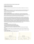
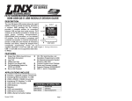
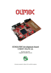
1
DK7121A User Manual
Table of contents
1.
2.
3.
4.
5.
6.
7.
Introduction
Kit Components
Definitions
Getting started
H/W Description
S/W Description
F/W Flowchart
Nov., 2007, Version 0.1 (PRELIMINARY)
1
AMIC Communication Corporation
DK7121A User Manual
1. Introduction
A7121 is a 2.4G FSK RF transceiver. The DK7121A is a development kit that helps engineers to
design and develop the kernel (transmission control) of 2.4G wireless applications such as keyboards,
mice, remote controls, gamepads, headsets and so on. The equipments you should prepare yourself are
one PC and two power supplies. After the system setup and run, the result of wireless transmission will
display on the screen as a format of PER. The detailed information of this development kit is available
in the document later. About the detailed control of A7121, please reference the source code and
A7121 application note and datasheet in the CD-ROM.
2. Kit Components
The DK7121A contains the following items:
z Two A7121 RF modules
z Two DK boards
z One RS232 cables
z CD ROM containing:
- DK7121A User Manual
- DK7121A quick start guide
- A7121 PER test program
- A7121 Datasheet
- Application note A7121
- Development Kit Source code
3. Definitions
PER (Packet Error Rate or Packet Error Ratio)
A PER is a procedure or device that measures the BER for a given transmission. This Development Kit
is a PERT that helps engineers learning how to control the RF chips through the providing firmware.
BER (Bit Error Rate or Bit Error Ratio)
BER is a measure of the accuracy of transmission for digital information in a telecommunication
system. It is the percentage of bits that are error relative to the total number of bits received in a
transmission, usually expressed as ten to a negative power. For example, a transmission might have a
BER of 10 to the minus 9, meaning that one bit was in error out of 1,000,000,000 transmitted bits. The
BER indicates how often a packet or other data unit has to be retransmitted because of an error. It
means the packets had to be resent would increase in a transmission if the BER is too high. Hence the
QoS became worse.
Nov., 2007, Version 0.1 (PRELIMINARY)
2
AMIC Communication Corporation
DK7121A User Manual
QoS (Quality of Service)
QoS implies the performance of a communication system. It may relate to some factors such as BER
(Bit Error Ratio), SNR (Signal to Noise Ratio), maximum and mean throughput rate, priority and
reliably, depending upon the communication system. BER is typically employed when expressing the
QoS in a transmission.
4. Getting started
We prepare a Quick Start Guide as a paper in the box of the package beyond the pdf file in the CDROM. The user can follow the simple software installation guide and step-by-step procedure to run the
one-way or two-way test very easily. Detailed descriptions about software installation and each step
will be given in the S/W part of this document. H/W part includes PCB board description, Pin
definition and schematic. F/W part includes the flowchart. The complete source code is allocated in the
CD-ROM.
5. H/W Description
5.1 Voltage supply
User can apply power to Jack J9 of the Board from a 5 ~ 10VDC supply. The on-board voltage
regulator generates a regulated +3.3VDC for the Board circuitry. The red Led shows whether the board
has power applied.
5.2 RS232 connection
The DK Board provides a DB-9 connection for a simply RS232 port. User uses the supplied RS232
cable to connect the DK Board to the PC’s serial port (COM1 or COM2). The DK board is connected
to a PC to be programmed by the software.
5.3 RF module expansion connection
The Board provides RF module expansion connectors for A7121 module. You should plug in RF
module on connector J8.
5.4 Jumper setting
5.4.1 J14 jumper setting: The TX data is sent to Pin TRXD of A7121 when Pin 1 & 2 is short. The
TX data is sent to Pin TXD of A7121 when Pin 2 & 3 is short.
Nov., 2007, Version 0.1 (PRELIMINARY)
3
AMIC Communication Corporation
DK7121A User Manual
J14 circuit
5.5 Push Button
The following table shows the push button function.
Push button
SW1 (MCU RESET)
Description
Reset MCU
5.6 LEDs
The Board provides three Leds. Refer to the table below for different Leds.
LED
D1 (Green)
D2 (Yellow)
D3 (Red)
Nov., 2007, Version 0.1 (PRELIMINARY)
Description
Config ok indirect
VGA gain indirect, On- 20dB,Off- 0dB
Power on indirect
4
AMIC Communication Corporation
DK7121A User Manual
5.7 ICE I/O connections
The following tables show the MCU pin assignments to I/O connections (JP1)
Signal name
SPI_CS
SPI_CLK
MCU_RXD
MCU_TXD
SPI_RXD
SPI_TXD
RX_SYN_
CD_TXEN
MCU_RST
P11
FCLK
MS0
MS!
NC
RF_RSTn
P18
P19
P20
P21
GND
NC
SEL_MS
GO_BUTTON
NC
NC
Nov., 2007, Version 0.1 (PRELIMINARY)
MCU pin #
2
3
4
5
6
7
8
9
10
11
13
14
15
16
17
18
19
20
21
22
1
12
JP1 pin #
1
2
3
4
5
6
7
8
9
10
11 12
13 14
15 16
17 18
19 20
21 22
23 24
25 26
27 28
29 30
31 32
33 34
35 36
37 38
39 40
41 42
43 44
45 46
47 48
49 50
5
MCU pin #
44
43
42
41
40
39
38
37
36
35
33
32
31
30
29
28
27
26
25
24
23
34
Signal name
+3.3V
P43
P42
P41
P40
P39
P38
P37
P36
+3.3V
P33
P32
P31
P30
P29
P28
P27
P26
P25
P24
NC
LED1
LED2
NC
NC
AMIC Communication Corporation
DK7121A User Manual
5.8 Development Board Placement
RS232 connection
Jumper
Voltage supply
ICE I/O
Push button
LEDs
MCU device
RF
module
expansion
5.9 Development Board Schematic
1
2
3
4
5
+3.3V
JP1
SPI_CS
SPI_CLK
MCU_RXD
MCU_TXD
SPI_RXD
SPI_TXD
RX_SYN
CD_TXEN
MCU_RST
P11
FCLK
MS0
MS1
0.1u
+3.3V
6
5
4
3
2
1
44
43
42
41
40
D
P43
P42
P41
P40
SPI_RXD
MCU_TXD
MCU_RXD
SPI_CLK
SPI_CS
SEL_MS
+3.3V C1
3
2
1
TXD
TRXD
CON3
SPI_TXD
RX_SYN
CD_TXEN
MCU_RST
P11
GO_BUTTON
FCLK
MS0
MS1
FP_RPY
RF_RSTn
7
8
9
10
11
12
13
14
15
16
17
INT3/P1.5
INT4/P1.6
INT5/P1.7
RST
RXD/P3.0
P4.3
TXD/P3.1
INT0/P3.2
INT1/P3.3
T0/P3.4
T1/P3.5
WR/P3.6
RD/P3.7
XTAL2
XTAL1
VSS
WAIT/P4.0
A8/P2.0
A9/P2.1
A10/P2.2
A11/P2.3
A12/P2.4
J14
INT2/P1.4
TXD1/P1.3
RXD1/P1.2
T2EX/P1.1
T2/P1.0
P4.2
VDD
AD0/P0.0
AD1/P0.1
AD2/P0.2
AD3/P0.3
U1
R1
10K
FP_RPY
RF_RSTn
P18
P19
P20
P21
J1
39
38
37
36
35
34
33
32
31
30
29
P0.4/AD4
P0.5/AD5
P0.6/AD6
P0.7/AD7
EA
P4.1
ALE
PSEN
P2.7/A15
P2.6/A14
P2.5/A13
P39
P38
P37
P36
LED2
P33
P32
P31
P30
P29
1
2
3
SEL_MS
CON3
+3.3V
SEL_MS
GO_BUTTON
LED1
P24
P25
P26
P27
P28
18
19
20
21
22
23
24
25
26
27
28
P18
P19
P20
P21
2
4
6
8
10
12
14
16
18
20
22
24
26
28
30
32
34
36
38
40
42
44
46
48
50
P43
P42
P41
P40
P39
P38
P37
P36
R3
+3.3V 150
D1
R4
+3.3V 150
D2
C2
0.1u
1
3
4
5
+3.3V
P33
P32
P31
P30
P29
P28
P27
P26
P25
P24
C3
0.1u
MCU_TXD 11
10
MCU_RXD 12
9
C1+
C1C2+
C2T1IN
T2IN
R1OUT
R2OUT
VCC
VS+
VS-
D
16
2
6
C4
LED1
LED2
Config_OK
C8
22P
C5
14 RS232_RXD
7
13 RX232_TXD
8
15
B
SPI_TXD
RX_SYN
CD_TXEN
MCU_RST
P11
GO_BUTTON
FCLK
MS0
MS1
1
2
3
4
5
6
7
8
9
10
11
FP_RPY
11 RF_RSTn
C
P29
P30
P31
P32
P33
LED2
P36
P37
P38
11 P39
J8
CON/18P 1.27
+3.3V
SPI_CS
SPI_CLK
SPI_RXD
SPI_TXD
RX_CLK
RX_SYN
CD_TXEN
TRXD
TXD
FCLK
RF_RSTn
MS0
MS1
BB_CLK
CON11
J7
P18
P19
P20
P21
1
2
3
4
5
6
7
8
9
10
11
LED1
P24
P25
P26
P27
11 P28
CON11
P40
P41
P42
P43
+3.3V
SEL_MS
SPI_CS
SPI_CLK
MCU_RXD
MCU_TXD
11 SPI_RXD
+3.3V
FP_RPY
SPI_CS
SPI_CLK
SPI_RXD
SPI_TXD
RX_CLK
RX_SYN
CD_TXEN
TRXD
TXD
FCLK
RESETn
MS0
MS1
BB_CLK
VIN
GND
1
2
3
4
5
6
7
8
9
10
11
12
13
14
15
16
17
18
B
CON11
J10
+3.3V
J11
1
2
+3.3V
SW1
1
6
2
7
3
8
4
9
5
DB9/F
CON11
1
2
3
4
5
6
7
8
9
10
11
R6
NC
0.1u
J3
T1OUT
T2OUT
R1IN
R2IN
GND
LED1
LED2
J6
R2
10K
C10
1U
0.1u
J5
1
2
3
4
5
6
7
8
9
10
11
VGA
Y1
+3.3V
C6
+3.3V 0.1u
U2
MAX232
IDC50P
W77E58/PLCC44
C724MHz
22P
1
3
5
7
9
11
13
15
17
19
21
23
25
27
29
31
33
35
37
39
41
43
45
47
49
J4
C
6
1
2
CON/2P 1.27
CON/2P 1.27
GO_BUTTON
MCU RESET
C9
NC
D3
POWER
MCU_RST
SW2
GO BUTTON
R7
100K
A
U4
3.3V
J9
VCC
1
2
1
C11
0.1U
Vin
C13
100U/16V
Vout
R5
470
+3.3V
3
A
C12
0.1U
C14
100U/16V
Title
A7121DK BOARD
2
CON2
Gnd
RF_RSTn
Size
Number
Revision
B
Date:
File:
1
2
Nov., 2007, Version 0.1 (PRELIMINARY)
3
4
6
5
4-May-2005
Sheet of
G:\DS\RF\PCB Layout\黃健鵬\A7121_TEST
Drawn
BOARD\A7121_TEST
By:
BOARD.ddb
6
AMIC Communication Corporation
DK7121A User Manual
6. S/W Description
The “A7121 PER (Packet Error Rate) test program” software run on window 98,window 2000 or
window XP operating system, and is used for controlling the DK board. The software communicates
with the DK board through the PC’s serial port.
z
To install A7121 PER test program
1) Insert the software into your CD-ROM drive.
2) Select “A7121 PER test program setup” item.
3) Follow the instructions given by the setup wizard for correct installation of the program.
z
To uninstall A7121 PER test program
Click the [Start] button under Windows.
Select “Control Panel” in Setup.
Double-click Add/Remove Programs.
Click Install/Uninstall. Then select “A7121 PER test program” from the list of programs that can be
automatically removed.
Click the [Remove...] button to uninstall “A7121 PER test program”.
z
To use A7121 PER test program: The A7121 PER test program Main Screen appears whenever
you execute the program. The screen is shown below.
Nov., 2007, Version 0.1 (PRELIMINARY)
7
AMIC Communication Corporation
DK7121A User Manual
Control panel
ComPort select
You can choose comport 1 or 2 to config the DK board. The default setting is COM 1.
Data rate
The data rate can be set 1Mbps or 3Mbps. The default setting is 1Mbps.
Channel
The channel can be set frequency from 2402 to 2480 MHz at data rate 1Mbps mode or frequency
from 2403 to 2479.5 MHz at data rate 3Mbps mode. The label Tx freq” and “Rx freq” is shown
frequency setting currently.
Test Data Pattern
The test data pattern can be set in one of two modes. Choosing “Fixed value (1 byte)”, you need
enter 1 byte value (hex value) in text field. The fixed value used on the channel being testing.
Choosing “PN9”, the data PN sequence used on the channel being testing.
Nov., 2007, Version 0.1 (PRELIMINARY)
8
AMIC Communication Corporation
DK7121A User Manual
Test Count
You can enter a value between 1 and 65535 for testing frame count.
Please note that the parameter on the control panel will become red color when it is modified.
B. Status list
Status
This status frame is shown PER information currently.
TX Frame: This value indicates transmitted packet.
RX Frame: This value indicates received packet
Frame Error Rate = Error Frame / RX Frame
Byte Error Rate 1 (w/o frame loss)= Error Byte / (RX Frame *64)
Byte Error Rate 2 (with frame loss)= (Error Byte + (Total Test Frame –RX Frame)*64) / (Total Test
Frame * 64 ).
Error list
After user pressed this “Read Error List” button while testing error occurred, the program will
display first 10 error bytes on ErrList frame.
Press ‘Clear” push button, the software will clear error list.
Nov., 2007, Version 0.1 (PRELIMINARY)
9
AMIC Communication Corporation
DK7121A User Manual
Tx transmit byte
Receive error
C. One-way or Two-way control page
“Config Master” or “Config Slave” push button
Press button “Config Master” or “Config Slave”, the software will send all parameters (one-way or
two-way mode, data rate, channel, data pattern) to MCU. If configuration data is valid, the button
back color becomes green. The green LED (LED2) on the DK board turn on indicates that the
A7121’s configuration is ok. If “Config Master” or “Config Slave” failed, error message is shown.
“Load Test Count” push button
Press button “Load Test Count”, the software will send test count value to MCU.
Nov., 2007, Version 0.1 (PRELIMINARY)
10
AMIC Communication Corporation
DK7121A User Manual
“Start” push button
Press button “Start” on master, the software will show a message to prompt whether the slave board
is ready or not. If yes, press “Ok” button to start PER testing and the back color of “Start” button
becomes to green.
“Stop” push button
Press ‘Stop” push button, the software will be stop testing.
D. Control Item
User can choose “OneWay” or “TwoWay” to do uni-directional or bi-directional PER testing. In the
“OneWay” mode, the master board is set as transmitted side and slave board is set as received side.
Nov., 2007, Version 0.1 (PRELIMINARY)
11
AMIC Communication Corporation
DK7121A User Manual
1.
Setup procedure
The following steps show users how to run the development kit test program example of One-Way
mode
1) Connect PC#1 RS232 com1 port to master board with RS232 cable, and connect another PC#2
RS232 com1 port to slave board with RS232 cable (or connect PC#1 RS232 com2 port to
slave board).
2) PC#2 setup procedures for slave board
(1) Select comport select > COM 1.
(2) Select data rate> 1Mbps.
(3) Select Channel> 2402MHz.
(4) Select test data pattern> Fixed value, and enter “B4” on text field (hex value).
(5) Test count enter “5000” on the text field (Decimal value).
(6) Select Control Item > OneWay > Slave(RX).
(7) Press Config Slave push button.
(8) Press Load Test Count push button.
(9) Press Start push button, and the A7121 on the slave board will be into RX mode.
3) PC#1 setup procedures for master board
(1) Select comport select > COM 1
(2) Select data rate> 1Mbps.
(3) Select Channel> 2402MHz.
(4) Select test data pattern> Fixed value, and enter “B4” on text field (hex value).
(5) Test count enter “5000” on the text field (Decimal value).
(6) Select Control Item > OneWay > Master(TX).
(7) Press Config Master push button.
(8) Press Load Test Count push button.
(9) Press Start push button, and then bring up a message “Please check Slave Board is
ready!!” .If the slave board is ready (i.e. A7121 is in RX mode), press “Ok” button to
start PER testing.
4) If the setup is correct, user can observe transmitted/received status on status list.
5) User can press “Stop” button to stop testing on master or slave board at any time. After stop
program, user can redo the PER testing program by following any step.
5.1 Press “Start” button to restart testing.
5.2 Modify “Test Count” value, and press “Load Test Count “ and “Start” button to restart
testing.
5.3 Modify any parameter on control panel, and redo above item 2) or 3) setup procedures
Nov., 2007, Version 0.1 (PRELIMINARY)
12
AMIC Communication Corporation
DK7121A User Manual
7. F/W Flowchart
Start
Init()
Check event
Config ok ?
N
Y
initRF ok ?
N
InitRF()
Y
Oneway master
Y
Oneway master()
N
Oneway slave
Y
Oneway slave()
N
Twoway master
Y
Twoway master()
N
Twoway slave
Nov., 2007, Version 0.1 (PRELIMINARY)
Y
Twoway slave()
13
AMIC Communication Corporation