1
Automation and control
Automation and relay functions
Schneider Electric Industries SAS
Headquarters
89, bd Franklin Roosevelt
F - 92506 Rueil Malmaison Cedex
http://www.schneider-electric.com
ART. 070455
Owing to changes in standards and equipment, the characteristics
given in the text and images in this document are not binding us
until they have been confirmed with us.
Production : Schneider Electric Industries
Photos : Schneider Electric Industries
Printed by :
December 2003
MKTED204011EN
Automation and relay functions
12-03
Catalogue
December
Art. 61231 - DIA6ED2030901EN
Distributed I/O
Advantys STB
Art. 67341 - MKTED203111EN
2003
Safety solutions
using Preventa
2004
Art. 55053 - MKTED203041EN
AS-Interface
cabling system
2003
Data-processing,
Communication
Control and Protection,
Detection,
Data-processing,
Man-Machine dialogue
Control and Protection,
Detection,
Data-processing,
Man-Machine dialogue,
Communication
The
Essential guide
To be issued: 1st quarter 2004
Art. 54752 - MKTED203031EN
Global Detection
Electronic and
electromechanical sensors
To be issued
2003
Automation and control
Mounting systems
Art. 70263 - MKTED203113EN
2004
Automation and control
Interfaces, I/O splitter boxes
and power supplies
2003
Art. 70455 - MKTED204011EN
Automation and control
Automation and relay functions
2003
Detection
Panel-building and cabling accessories
AUTC201108140EN
Transparent factory
The future of automation
2003
AUTC201104124EN
Momentum
automation platform
AUTC201384126EN
2002
Quantum
automation platform
AUTC201496125EN
Premium
automation platform
2003
AUTC101272123EN
2003
2001
Nano
programmable controllers
and
Micro
automation platform
Data-processing,
Man-Machine dialogue,
Communication,
Supervision
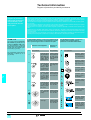
An overview
of the product range
- Safety solutions using Preventa,
- Global Detection,
- AS-Interface,
- Control and connection components,
- Motor starter solutions
(Control and protection components),
AUTC20176206EN
- Soft starters and variable speed drives
Twin Line
Motion control
AUTCD21124207EN
2003
Lexium
Motion control
Art. 46753 - MKTED203011EN
2002
Soft starters and
variable speed drives
Art. 27501 - MKTED201001EN
Art. 28697 - MKTED299014EN
Motor starter solutions
Control and protection
components
Telemecanique
Components for
Human-Machine interfaces
2001
Man-Machine dialogue
2003
2001
Control and protection
Automation solutions
An overview of the product range
tico 732
E
5
6
3
4
1
2
R
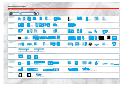
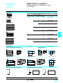
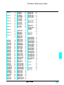
Products listed in this catalogue
Product listed in other catalogues (see previous pages)
Control and
protection
Contactors
from 6 to 16A
Contactors
Contactors
from 9 to 150 A from 185 to 800 A
Modular contactors
Circuit-breakers
Rotary switch disconnector
Thermal overload relays
Measurement and
control relays
Motor starters open version
Ready-assembled
variable speed drives
Power supplies and transformers
Limit switches for safety
applications
Electromechanical pressure
and vacuum switches
Electronic pressure
and vacuum switches
TBX distributed I/O
Advantys STB
distributed I/O
Contactor and reversing
contactor breakers
Direct on-line starters,
enclosed version
Star-delta starters,
enclosed version
Connectors
Encoders
Inductive identification system
Telefast ® 2 pre-wired
system
Interfaces
Control and
protection
Soft starters open and
enclosed version
Soft start-soft stop units
for asynchronous motors
Variable speed drives for asynchronous motors
Photo-electric
detectors
Inductive, capacitive, magnet and ultrasonic
proximity sensors
Detection
Limit switches
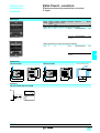
Data processing
Twido programmable
controllers
Nano programmable
controllers
Micro
automation platform
Premium
automation platform
Quantum
automation platform
Momentum
automation platform
IP 67 splitter boxes
Human-Machine
dialogue
Control
relays
Electronic
timing relays
Zelio Logic
smart relays
Preventa safety
modules
tico 732
E
5
6
3
4
1
2
R
Control and signalling units
Cam switches
Control stations
Pendant control stations
Operator dialogue terminals
Industrial control stations
Integrated Human-Machine Illuminated beacons
and indicator banks
interfaces
Totalising timers
and counters
Foot switches
Emergency stop stations
Tego Dial
Tego Power
Terminal blocks
Cable ends
Marking accessories
Emergency stop
trip wire switches
Communication
Communication architecture: Ethernet network, Modbus Plus network, Fipway network, AS-i bus, Fipio bus,
CANopen bus, Uni-Telway bus, Modbus bus, INTERBUS, Profibus DP, asynchronous serial links
Supervision
Monitor Pro software
Magelis IPC industrial PC
Vijeo Look software
Wall-mounted enclosures
Floor-standing enclosures Uprights, mounting plates, mounting rail,
cable ducting and cable clips
Prefadis service poles and posts,
lighting poles
Canalis busbar trunking for lighting distribution
Product reference index
Technical information
Panel building
and cabling
accessories
Prefabricated busbar systems and
power distribution systems
Profil front panel
Power
distribution
Canalis busbar trunking for low and medium power distribution
Services
Schneider Electric worldwide
Canalis busbar trunking for high power distribution
Mobile distribution: Canalis track section and cable carriers
Tools
General contents
0
Automation and control
Automation and relay functions
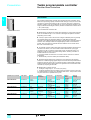
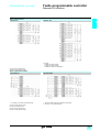
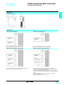
1 – Twido programmable controllers
Selection guide for compact and modular base controllers . . . . . . . . .page 1/2
Compact base controllers . . . . . . . . . . . . . . . . . . . . . . . . . . . . . . . . . . . . .page 1/8
Modular base controllers. . . . . . . . . . . . . . . . . . . . . . . . . . . . . . . . . . . . .page 1/14
Selection guide for discrete I/O modules. . . . . . . . . . . . . . . . . . . . . . . .page 1/16
Discrete I/O modules . . . . . . . . . . . . . . . . . . . . . . . . . . . . . . . . . . . . . . . .page 1/22
Selection guide for analogue I/O modules. . . . . . . . . . . . . . . . . . . . . . .page 1/26
Analogue I/O modules . . . . . . . . . . . . . . . . . . . . . . . . . . . . . . . . . . . . . . .page 1/30
Master module for AS-Interface bus. . . . . . . . . . . . . . . . . . . . . . . . . . . .page 1/33
Communication . . . . . . . . . . . . . . . . . . . . . . . . . . . . . . . . . . . . . . . . . . . .page 1/35
Communication protocols . . . . . . . . . . . . . . . . . . . . . . . . . . . . . . . . . . . .page 1/36
Pre-wired solutions . . . . . . . . . . . . . . . . . . . . . . . . . . . . . . . . . . . . . . . . .page 1/39
TwidoSoft programming software . . . . . . . . . . . . . . . . . . . . . . . . . . . . .page 1/46
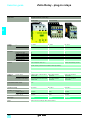
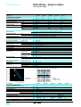
2 – Zelio Relay - plug-in relays
Selection guide for control relays and plug-in control relays . . . . . . . .page 2/2
Universal relays . . . . . . . . . . . . . . . . . . . . . . . . . . . . . . . . . . . . . . . . . . . . .page 2/5
Miniature relays . . . . . . . . . . . . . . . . . . . . . . . . . . . . . . . . . . . . . . . . . . . . .page 2/8
Interface relays . . . . . . . . . . . . . . . . . . . . . . . . . . . . . . . . . . . . . . . . . . . . .page 2/11
3 – Zelio Time - timing relays
Selection guide for Zelio Time - timing relays . . . . . . . . . . . . . . . . . . . . .page 3/2
Modular relays, solid state output . . . . . . . . . . . . . . . . . . . . . . . . . . . . . .page 3/6
Industrial relays, solid state output . . . . . . . . . . . . . . . . . . . . . . . . . . . .page 3/10
Modular relays, relay output . . . . . . . . . . . . . . . . . . . . . . . . . . . . . . . . . .page 3/14
Industrial single or multifunction relays . . . . . . . . . . . . . . . . . . . . . . . .page 3/18
Industrial single-function relays, relay output. . . . . . . . . . . . . . . . . . . .page 3/26
Industrial single or multifunction relays, relay output . . . . . . . . . . . . .page 3/28
Industrial, single-function relays, optimum, relay output . . . . . . . . . .page 3/34
Universal plug-in relays, 8-pin, relay output . . . . . . . . . . . . . . . . . . . . .page 3/40
Universal plug-in relays, 11-pin, relay output . . . . . . . . . . . . . . . . . . . .page 3/44
Miniature plug-in relays, relay output. . . . . . . . . . . . . . . . . . . . . . . . . . .page 3/47
Panel-mounted, plug-in, universal relays . . . . . . . . . . . . . . . . . . . . . . .page 3/51
4 – Zelio Count - counters
Electromechanical hour counters. . . . . . . . . . . . . . . . . . . . . . . . . . . . . . .page 4/3
Electromechanical totalising counters. . . . . . . . . . . . . . . . . . . . . . . . . . .page 4/5
Electromechanical preselection counters . . . . . . . . . . . . . . . . . . . . . . . .page 4/7
Electronic preselection and multifunction counters. . . . . . . . . . . . . . . .page 4/9
1
3
1/0
-
Contents
0
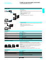
1 - Twido programmable controller
Selection guide for compact and modular base controllers . . . . . . . . . page 1/2
# Compact base controllers . . . . . . . . . . . . . . . . . . . . . . . . . . . . . . . . . . . . page 1/8
# Modular base controllers . . . . . . . . . . . . . . . . . . . . . . . . . . . . . . . . . . . . page 1/14
Selection guide for discrete I/O modules. . . . . . . . . . . . . . . . . . . . . . . page 1/16
# Discrete I/O modules . . . . . . . . . . . . . . . . . . . . . . . . . . . . . . . . . . . . . . . page 1/22
Selection guide for analogue I/O modules . . . . . . . . . . . . . . . . . . . . . . page 1/26
# Analogue I/O modules . . . . . . . . . . . . . . . . . . . . . . . . . . . . . . . . . . . . . . page 1/30
# Master module for AS-Interface bus . . . . . . . . . . . . . . . . . . . . . . . . . . . page 1/33
# Communication . . . . . . . . . . . . . . . . . . . . . . . . . . . . . . . . . . . . . . . . . . . page 1/35
# Communication protocols . . . . . . . . . . . . . . . . . . . . . . . . . . . . . . . . . . . page 1/36
# Pre-wired solutions . . . . . . . . . . . . . . . . . . . . . . . . . . . . . . . . . . . . . . . . page 1/39
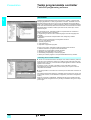
# TwidoSoft programming software
5 User interface . . . . . . . . . . . . . . . . . . . . . . . . . . . . . . . . . . . . . . . . . . page 1/41
5 Programming . . . . . . . . . . . . . . . . . . . . . . . . . . . . . . . . . . . . . . . . . . . page 1/42
5 Integrated functions, software set-up. . . . . . . . . . . . . . . . . . . . . . . . . page 1/43
5 Integrated counter and positioning functions . . . . . . . . . . . . . . . . . . . page 1/44
5 TwidoSoft programming software . . . . . . . . . . . . . . . . . . . . . . . . . . . page 1/47
1/1
1
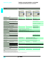
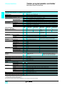
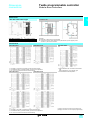
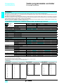
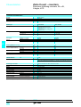
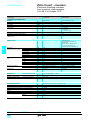
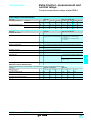
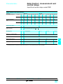
Selection guide
1
Twido programmable controller
1
Compact and modular base controllers
Applications
Compact base controllers
1
Discrete I/O
Basic
Number of inputs
Number of outputs
Type of connection
I/O expansion
10
16
6 sink/source $ 24 V inputs
9 sink/source $ 24 V inputs
(1)
(1)
4 relay outputs
7 relay outputs
Non-removable screw terminal block
24
14 sink/source $ 24 V inputs
(1)
10 relay outputs
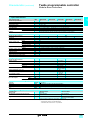
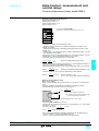
Number of expansion modules
4 discrete, analogue and
Discrete I/O modules
8, 16 or 32 $24 V inputs;
Analogue I/O modules
AS-Interface (3)
2 x 12 bit inputs; 1 x 12 bit output
Management of slave modules:
Maximum number of I/O per configuration
(base controller with I/O expansion module)
10
Integrated counting
and positioning
3 x 16 bit counting channels (0...65535 points):
- dedicated $ 24 V discrete inputs of the base controller
- up/down counting with preset
1 x 16 bit counting channel (0...65535 points):
- dedicated $ 24 V discrete inputs for incremental encoder or proximity sensors
- up/down counting, up counter, down counter and frequency meter
5 kHz counting
20 kHz counting
16
88 with screw terminal
I/O expansion modules (4)
152 with HE 10 connector
I/O expansion module
7 kHz positioning
Functions
PID
For all controller versions ≥ 2.0
Event processing
For all controller versions ≥ 2.0
Communication
1 RS 485 serial port
(mini-DIN connector)
Supply voltage
" 100...240 V supply ($ 24 V discrete sensors powered by the base controller)
Programming
Application memory
Internal bits
Internal words (5)
Standard function blocks (5)
Double words
Floating, Trigonometrical
Real-time clock
Languages
Software
Twido base controller models
700 instructions
128 bits
3000
64 timers, 128 counters
1 RS 485 serial port (mini-DIN connector)
1 optional serial port: RS 232C (mini-DIN connector) or
RS 485 (mini-DIN connector or screw terminals)
2000 instructions
128 bits
128 timers,
Yes
Optional TWD XCP RTC real time clock cartridge, using 16 real-time clock blocks
Reversible languages: Ladder language and Instruction List language (with Grafcet instructions)
TwidoSoft running under Windows 98 SE, Windows 2000 and Windows XP
TWD LCAA 10DRF TWD LCAA 16DRF TWD LCAA 24DRF
Page
1/8
(1) Sink input: positive logic. Source input: negative logic.
(2) Within the consumption limit controlled by TwidoSoft software.
(3) The AS-Interface M3 profile supports analogue profile 7.3 (7 slaves), but not analogue profile S-7.4.
1/2
3000 instructions
256 bits
1
1
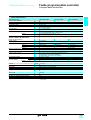
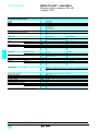
Modular base controllers
1
20
12 sink/source $ 24 V inputs (1)
40
24 sink/source $ 24 V inputs (1)
8 sink or source transistor outputs (depending on model)
HE 10 connector
6 relay outputs and 2 transistor source outputs
Removable screw terminal block
16 sink or source transistor outputs (depending on model)
HE 10 connector
AS-Interface I/O modules (2)
7 discrete, analogue and AS-Interface I/O modules (2)
8, 16 or 32 $ 24 V or relay outputs; 4 $ 24 V inputs/4 relay outputs or 16 $ 24 V inputs/8 relay outputs, connection by screw or spring terminals and by
HE 10 connector
or 2 inputs/1 x 12 bit output, connection by screw terminals
discrete (max. 62 modules), analogue (max. 7 modules). For all controller versions ≥ 2.0
84 with screw terminal I/O expansion module
148 with HE 10 connector I/O expansion module
132 with screw terminal I/O expansion module
244 with HE 10 connector I/O expansion module
152 with screw terminal I/O expansion module
264 with HE 10 connector I/O expansion module
2 x 16 bit channels (0...65535 points):
- dedicated discrete inputs of the base controller
- up/down counting with preset
2 x 16 bit channels (0...65535 points):
- dedicated $ 24 V discrete inputs for incremental encoders or proximity sensors
- up/down counting, up counter, down counter, frequency meter
2 channels: PWM function (pulse width modulation output) and PLS function (pulse generator output)
For all controller versions ≥ 2.0
For all controller versions ≥ 2.0
$ 24 V power supply
3000 instructions, 6000 with memory extension cartridge TWD XCP MFK64
128 counters
Yes
TWD LMDA 20D/K (6)
TWD LMDA 20DRT
TWD LMDA 40D/K (6)
1/14
(4) With maximum of 42 relay outputs (on base controller and I/O expansions).
(5) The maximum values of the internal words and function blocks cannot be cumulated.
(6) Replace the / in the reference with T: source transistor outputs, U: sink transistor outputs
1/3
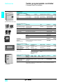
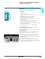
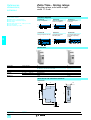
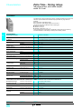
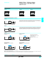
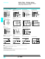
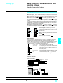
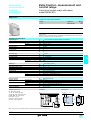
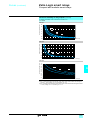
Presentation
1
Twido programmable controller
Compact base controllers
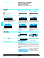
Presentation
1
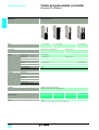
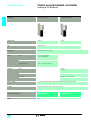
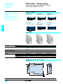
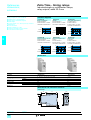
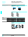
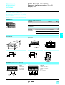
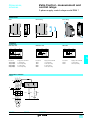
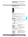
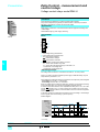
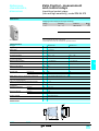
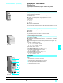
The Twido range of compact programmable controllers offers an "all-in-one" solution
in a compact overall size (80/95 x 90 x 70 mm).Three base controllers are available,
differing in their processing capacity and their number of $ 24 V inputs and relay
outputs (10, 16 and 24 I/O). All these compact base controllers use an a.c. power
supply between 100 and 240 V and provide a $ 24 V supply to the sensors.
This type of compact base controller offers the following advantages:
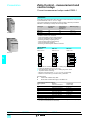
TWD LCAA 10DRF
# A significant number of I/O (up to 24 I/O) in a small overall size, so reducing the
size of consoles or panels for applications where space is an important factor.
# A variety of expansion options and product options offer the user a degree of
flexibility which is generally only available with larger automation platforms. The
TWD LCAA 24DRF 24 I/O compact base controller can take up to 4 discrete I/O
expansion modules (corresponding to a 64 I/O configuration), optional modules such
as a digital display, memory cartridge and real-time clock cartridge, as well as an
additional RS 485 or RS 232C communication port.
# The compact controller solution also allows great wiring flexibility. For expansion
modules (with base controller TWD LCAA 24DRF) several types of connection are
offered, such as removable screw terminal blocks, and spring type connections
which allow simple, fast and safe wiring. The TwidoFast system provides a pre-wired
cabling solution, allowing connection of modules with HE 10 connectors to:
5 pre-formed cables with free wires at one end for direct connection to sensors/
preactuators,
5 TwidoFast kits (connection cables plus Telefast sub-base).
TWD LCAA 16DRF
# The display and plug-in memory options allow easy adjustment, transfer and
backup of applications:
5 the digital display can be used as a local display and adjustment tool,
5 the EEPROM technology in the memory modules allows backup and transfer of
programs to any Twido compact or modular controller.
TWD LCAA 24DRF
# TwidoSoft software allows easy programming using instruction list language
instructions or ladder language graphic objects. It uses the same objects and sets of
instructions as those used by PL7-07 software for Nano programmable controllers.
TwidoSoft software allows existing Nano PLC applications to be reused with Twido
controllers by importing an ASCII file.
# Compact controllers have 2 analogue adjustment points (only one for 10 I/O
controllers) accessible on the front panel. These adjustable values are stored in
system words and are updated at every scan.
Analogue
adjustment
1 point
0…1023
Serial ports
I/O expansion
TWD LCAA 10DRF
$ 24V inputs Relay
outputs
6
4
1 x RS 485
TWD LCAA 16DRF
9
7
1 point
0…1023
1 x RS 485,
+ option of
1 x RS 232C/485
TWD LCAA 24DRF
14
10
Compact base controller
1/4
Optional cartridge
No
Display
module
Yes
No
Yes
1 slot:
real-time clock
or memory
1 slot:
real-time clock
or memory
1 point
1 x RS 485,
Yes, 4 max
Yes
1 slot:
0…1023
+ option of
(1)
real-time clock
1 point
1 x RS 232C/485
or memory
0…511
(1) I.e.: a maximum of 88 I/O with screw terminal expansion modules, with a maximum of 32 relay
outputs in I/O expansion modules.
Maximum of 152 I/O with HE 10 connector expansion modules.
1
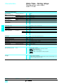
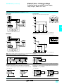
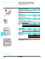
Description
1
Twido programmable controller
1
Compact base controllers
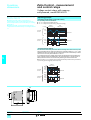
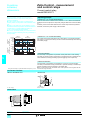
Description
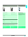
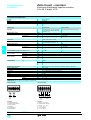
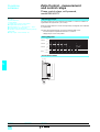
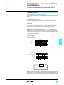
Twido TWD LCAA // DRF compact programmable base controllers comprise:
2
3
4
1 Two hinged connection terminal block covers for access to the terminals.
5
1
6
7
1
8
12 11 10 9
2 A hinged access door.
3 A mini-DIN type RS 485 serial port connector (allowing connection of the
programming terminal).
4 A slot (protected by a removable cover) for digital diagnostic/maintenance display
module TWD XCP ODC.
5 A screw terminal block for $ 24 V supply to the sensors and for connection of the
input sensors.
6 A connector for I/O expansion modules TWD D//, TWD A// and TWD NOI 10M3
(maximum of 4 on 24 I/O models).
7 A display block showing:
- the status of the controller (PWR, RUN, ERR and STAT),
- the inputs and outputs (IN/ and OUT/).
8 A screw terminal block for connection of the output preactuators.
9 Two analogue adjustment points (one point for 10 and 16 I/O models).
10 An extension connector for the addition of a 2nd RS 232C/RS 485 serial port using
adapter TWD NAC /// (for 16 and 24 I/O models).
11 A screw terminal block for connection of the " 100...240 V mains power supply
12 A connector for the TWD XCP MFK32 memory cartridge or TWD XCP RTC realtime clock cartridge (access through the bottom of the controller).
Compact base controllers can be mounted on a symmetrical DIN rail, mounting plate
or panel (2 x 4.3 Ø holes).
1/5
1
Characteristics
1
Twido programmable controller
Compact base controllers
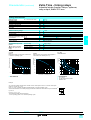
Characteristics of compact base controllers
1
Temperature
Relative humidity
Degree of protection
Altitude
Vibration resistance
Operation
Storage
°C
°C
Operation
Storage
Mounted on rail
m
m
Hz
m/s2
Hz
m/s2
Plate or panel mounted
(using fixing kit
TWD XMT5)
Shock resistance
Backup battery
m/s2
Data backed up
Autonomy
Battery type
Charging time
Life
Base controller type
Number of $ 24 V inputs
Number and type of outputs
Connection of I/O
I/O expansion modules Max. no. of modules
Max. no. of I/O
AS-Interface
Application memory capacity
Cycle time
Processing time
System overhead
Data memory
Internal bits
Internal words (2)
Timers (2)
Counters (2)
Double words
Power supply
Rated voltage
Voltage range
Maximum inrush current
$ 24 V sensor supply
Maximum power
" 100 V
required
" 264 V
days
h
years
ms
ms
V
V
A
mA
VA
VA
0…+ 55
- 25…+ 70
30 to 95 %, without condensation
IP 20
0…2000
0…3000
10…57, amplitude 0.075 mm, acceleration 57…150 Hz
9.8 (1 gn)
2…25, amplitude 1.6 mm, acceleration 25…100 Hz
39.2 (4 gn)
147 (15 gn) for 11 ms
Internal RAM: internal variables, internal bits and words, timers, counters, shift registers...
Approximately 30 at 25 °C with fully charged battery
Lithium battery, not interchangeable
Approximately 15 to charge from 0…90% of the full charge
10
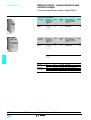
TWD LCAA 10DRF
TWD LCAA 16DRF
TWD LCAA 24DRF
6
9
14
4 relay
7 relay
10 relay
Non-removable screw terminal block
–
4
–
88/152 (1)
–
Management of slave modules: 62 (discrete), 7 (analogue)
700 instructions
2000 instructions
3000 instructions
1 for 1000 logic instructions
0.5
128
256
3000
64
128
128
–
Yes
" 100…240
" 85…264
35
40
250
20
22
33 (base with 4 I/O expansion
modules)
30
31
40 (base with 4 I/O expansion
modules)
Communication
Function
Port type
Built-in serial link
RS 485
Maximum data rate
Isolation between internal circuit and serial port
Programming terminal connection
Communication protocols
Remote Link I/O
K bits/s
38.4
Not isolated
Half-duplex terminal port
Modbus Master/Slave RTU
ASCII character mode
Yes, see page 1/37
Optional serial interface adapter (3)
RS 232C, with adapter TWD NAC 232D
RS 485, with adapter TWD NAC 485/
No
Integrated functions
Counter
PID
Event processing
Analogue adjustment
points
1/6
Number of points
Frequency
Capacity
24 I/O base controllers
10/16/24 I/O base controllers
24 I/O base controllers
4
3 channels at 5 kHz (function FCi), 1 channel at 20 kHz (function VFCi)
16 bits (0...65535 points)
For controller versions ≥ 2.0
For controller versions ≥ 2.0
1 point adjustable from 0…1023 points
1 point adjustable from 0…511 points
(1) The first value corresponds to the maximum number of I/O (base controller and expansion
module) with screw or spring terminal expansion modules, the second value is for HE 10
connector expansion modules.
(2) The maximum values cannot be cumulated.
(3) With 16 I/O base controller TWD LCAA 16DRF and 24 I/O base controller
TWD LCAA 24DRF.
1
Characteristics (continued)
1
Twido programmable controller
1
Compact base controllers
$ input characteristics
Base controller type
Number of input channels
Rated input voltage
Commons
Input voltage range
Rated input current
V
V
mA
Input impedance
Filter time
kΩ
At state 1
µs
At state 0
µs
Isolation
TWD LCAA 10DRF
TWD LCAA 16DRF
TWD LCAA 24DRF
6
9
14
$ 24 sink/source (positive or negative logic)
1
$ 20.4...28.8
11 mA for I0.0 and I0.1,
7 mA for other inputs I0.i
2.1 kΩ for I0.0 and I0.1,
3.4 kΩ for other inputs I0.i
35 µs programmed filter time for I0.0…I0.5,
40 µs or programmed filter time for other inputs I0.i
45 µs programmed filter time for I0.0…I0.5,
150 µs or programmed filter time for other inputs I0.i
No isolation between points, isolation with internal logic by photocouplers
1
Relay output characteristics
Number of output channels
Output currents
Commons
A
Common 0
Common 1
Common 2
Common 3
Minimum switching load
mA
Contact resistance (when new)
Loads (resistive, inductive)
mΩ
A
rms insulation voltage
Consumption
for all the outputs
At state 1
At state 0
$5V
$ 24 V
$5V
V
mA
mA
mA
4
2 per channel,
8 per common
3 N/O contacts
1 N/O contact
–
–
0.1/0.1 $ V (reference value)
7
10
4 N/O contacts
2 N/O contacts
1 N/O contact
4 N/O contacts
4 N/O contacts
1 N/O contact
1 N/O contact
30 max
2A/" 240 V or 2A/$ 30 V (with 1800 operations/hour max):
- electrical life: minimum 100 000 operations,
- mechanical life: minimum 20 x 106 operations.
"1 500 for 1 minute
24
30
26
40
5
5
36
55
5
Real-time clock cartridge (optional) (1)
Precision
Autonomy
Battery type
Charging time
Life
s/month + 30 at 25 °C
days
Approximately 30 at 25 °C with fully charged battery
Lithium battery, not interchangeable
h
Approximately 10 to charge from 0...90 % of the full charge
years
10
Memory cartridge (optional) (1)
Memory type
Memory capacity
Save/transfer program and internal words
Program size increase
Kb
EEPROM
32
Yes
No
(1) Compact base controllers have only one cartridge slot, therefore only one type of cartridge
can be used.
1/7
References
1
Twido programmable controller
1
Compact base controllers
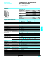
References
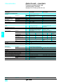
Compact base controllers
1
Number
of I/O
10 I/O
Inputs
sink/source
6 $ 24 V inputs
Outputs
Program memory
Reference
4 relay outputs
700 instructions
Weight
kg
TWD LCAA 10DRF
0.230
16 I/O
9 $ 24 V inputs
7 relay outputs
2000 instructions
TWD LCAA 16DRF
0.250
24 I/O
14 $ 24 V inputs
10 relay outputs
3000 instructions
TWD LCAA 24DRF
0.305
Application
Type
Reference
EEPROM
TWD XCP MFK32
Real-time clock cartridge
Application backup
Program transfer
Date-stamping RTC based programming
–
TWD XCP RTC
Serial interface adapter
See page 1/35
–
TWD NAC ////
–
Digital display
Data display and modification
–
TWD XCP ODC
0.020
Input simulators
6 inputs
–
TWD XSM 6
–
9 inputs
–
TWD XSM 9
–
14 inputs
–
TWD XSM 14
–
TWD LCAA 10DRF/16DRF/24DRF
Separate components (1)
Description
32 Kb memory cartridge
TWD XCP MFK32/RTC
TWD NAC ////
Description
Fixing kit
(Sold in packs of 5)
Application
Reference
For fitting compact base controllers or extensions
on a mounting plate
TWD XMT5
Weight
kg
0.005
0.005
Weight
kg
–
TWD XCP ODC
Magelis compact displays
Description
XBT N401
Compact display,
2 lines of 20 characters
(alphanumeric display)
Compact displays,
4 lines of 20 characters
(matrix display)
Protocol
Uni-Telway,
Modbus
Uni-Telway,
Modbus
Compatible with
PLC types
Twido, Nano, Micro,
Premium
Twido, Nano, Micro,
Premium
Twido (2) Nano, Micro,
Premium, TSX series 7,
Momentum, Quantum
Other Modbus slave
modules
Supply voltage
Reference
$ 5 V by terminal
port on PLC
XBT N200
Weight
kg
0.360
$ 5 V by terminal
port on PLC
$ 24 V external
source
XBT N400
0.360
XBT N401
0.360
Phaseo regulated power supply
Description
Regulated switch mode
power supply for
AS-Interface bus (3)
ASI ABLM3024
1/8
Mains input Output
Rated
Rated
Auto-protect Reference
Weight
voltage
voltage power
current
reset
47…63 Hz
V
$V
W
A
kg
" 100…240 30 + 24
2 x 72
2.4 + 3
Auto
ASI ABLM3024
1.300
single-phase
wide range
(1) Other separate components, see page pages 1/35 and 1/39.
(2) Connection via built-in port or optional serial port on Twido programmable controllers.
(3) With earth fault detection.
Twido programmable controller
Dimensions,
connections
1
1
Compact base controllers
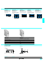
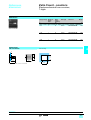
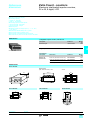
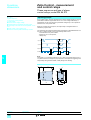
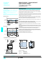
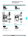
Dimensions
TWD LCAA 10DRF/16DRF/24DRF
1
Installation rules
a
70
20
90
40
40
20
4,5
TWD LCAA 10 DRF
TWD LCAA 16 DRF
TWD LCAA 24 DRF
a
80
80
95
20
80
20
Important:
# Vertical mounting: not permissible for temperatures 4 40° C, “upside down” flat mounting not
permissible.
# Avoid placing devices which generate heat (transformers, power supplies, power
contactors...) beneath the controller.
Connections
Connection of $ 24 V inputs
Connection of " 100…240 V power supplies and relay outputs
TWD LCAA 10DRF/16DRF/24DRF
TWD LCAA 10DRF
Connection to sink inputs (positive logic) with sensors powered
by the base controller.
TWD LCAA 16DRF
Connection to source inputs (negative logic) with sensors
powered by the base controller.
TWD LCAA 24DRF
1/9
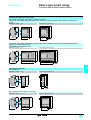
Presentation
1
Twido programmable controller
Modular base controllers
Presentation
1
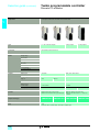
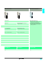
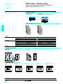
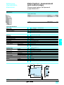
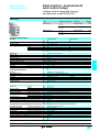
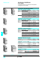
The modular programmable controller range includes five base controllers, which
differ in their processing capacity and their number and type of I/O (20 or 40 I/O with
connection by screw terminal block or HE 10 connector, with relay or sink/source
transistor outputs). They can be fitted with any of the I/O expansion modules in the
range (18 discrete and analogue modules). All these modular base controllers use a
$ 24 V power supply.
These modular base controllers offer:
TWD LMDA 20DTK/20DUK
# Modular design to adapt to the needs of the application by using a base controller
which can be fitted with up to 4 or 7 discrete or analogue I/O expansion modules
(depending on the model).
# A variety of options which offer the user a degree of flexibility which is generally
only available with larger automation platforms. TWD LMDA modular base
controllers can be fitted simultaneously with an optional memory cartridge module, a
real-time clock cartridge module and a digital display module or serial interface
module; both of the latter two modules allow the addition of a second RS 485 or
RS 232C communication port.
# The modular controller solution also allows great wiring flexibility. Several types of
connection are offered, such as removable screw terminal blocks, spring type
connections or HE 10 connectors which allow simple, fast and safe wiring. The
TwidoFast system provides a pre-wired cabling solution, allowing connection of
modules with HE 10 connectors to:
5 pre-formed cables with free wires at one end for direct connection to sensors/
preactuators,
5 TwidoFast kits (connection cables plus Telefast sub-base).
TWD LMDA 20DRT
# TwidoSoft software allows easy programming using instruction list language
instructions or ladder language graphic objects. It uses the same objects and sets of
instructions as those used by PL7-07 software for Nano programmable controllers.
TwidoSoft software allows existing Nano PLC applications to be reused with Twido
controllers by importing an ASCII file.
TWD LMDA 40DTK/40DUK
# Modular base controllers include:
5 1 analogue voltage input, 0...10 V 9 bits (512 points),
5 1 analogue adjustment point accessible on the front panel. This point can be set
to a value between 0 and 1024. This adjustable value from 0...1023 points is stored
in system words and is updated at every scan.
Modular base controller $ 24V inputs
TWD LMDA 20DTK
12 sink/source
TWD LMDA 20DUK
12 sink/source
TWD LMDA 20DRT
12 sink/source
TWD LMDA 40DTK
24 sink/source
TWD LMDA 40DUK
24 sink/source
1/10
Outputs
8 source
transistor
Type of
connection
Serial ports
HE 10 connector 1 x RS 485,
+ option of
1 x RS 232C/485
8 sink transistor
HE 10 connector 1 x RS 485,
+ option of
1 x RS 232C/485
6 relay,
Removable
1 x RS 485,
2 source
screw terminal
+ option of
transistor
block
1 x RS 232C/485
16 source
HE 10
1 x RS 485,
transistor
connectors
+ option of
1 x RS 232C/485
16 sink transistor HE 10
1 x RS 485,
connectors
+ option of
1 x RS 232C/485
I/O expansion
4 modules
4 modules
7 modules
7 modules
7 modules
Interface
module
extension
1 module:
display or
serial link
1 module:
display or
serial link
1 module:
display or
serial link
1 module:
display or
serial link
1 module:
display or
serial link
Optional
cartridge
2 slots: real-time
clock and
memory
2 slots: real-time
clock and
memory
2 slots: real-time
clock and
memory
2 slots: real-time
clock and
memory
2 slots: real-time
clock and
memory
1
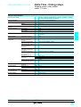
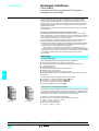
Description
1
Twido programmable controller
1
Modular base controllers
Description
1 2 3
1
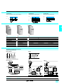
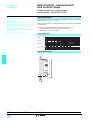
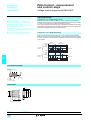
Twido TWD LMDA /0 D// base controllers comprise:
4
On the front panel:
1 A hinged door.
5
9
8
2 An analogue adjustment point.
3 A connector for connection of the built-in analogue input.
6
4 A display block showing:
- the status of the controller (PWR, RUN, ERR and STAT),
- the status of the inputs and outputs (INi and OUTi).
7
5 A mini-DIN type RS 485 serial port connector (allowing connection of the
programming terminal).
6 Two slots (protected by a removable cover) for memory cartridge
TWD XCP MFK//and real-time clock cartridge TWD XCP RTC.
7 One (or more) HE 10 type connector(s) or screw terminal block for connection of
the input sensors/output preactuators.
8 Screw terminals for connection of the $ 24 V mains power supply.
On the right-hand side panel:
9 A connector for I/O expansion modules TWD D//, TWD A// and
TWD NOI 10M3 (4 or 7 depending on model).
On the left-hand side panel:
A connector for display module TWD XCP ODM or serial interface module
TWD NOZ //// (not visible).
Modular base controllers are mounted on a symmetrical DIN rail. Fixing kit
TWD XMT5 (supplied in lots of 5) allows plate or panel mounting.
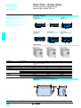
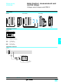
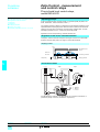
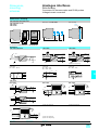
Example of configuration with expansion modules and extension
Shown opposite, an example configuration consisting of a TWD LMDA 20DRT
modular base controller with:
# built-in display module TWD XCP ODM on the left,
# two I/O expansion modules TWD DDI 8DT and TWD DDO 16K on the right.
The modular base controller is fitted with real-time clock cartridge TWD XCP RTC
and memory extension cartridge TWD XCP MFK64.
1/11
Characteristics
1
Twido programmable controller
Modular base controllers
General characteristics of modular base controllers
1
Temperature
Relative humidity
Degree of protection
Altitude
Vibration resistance Mounted on rail
Plate or panel mounted
(using fixing kit TWD XMT5)
Shock resistance
Backup battery
Data backed up
Autonomy
Battery type
Charging time
Life
Base controller type
Number of $ 24 V inputs
Number and type of outputs (1)
°C
m
Hz
m/s2
Hz
m/s2
m/s2
days
h
years
TWD
Connection of I/O
I/O expansion
modules
Max. no. of modules
Max. no. of I/O
AS-Interface
Application memory capacity
Cycle time
Data memory
Power supply
Processing time
System overhead
Internal bits
Internal words (3)
Timers (3)
Counters (3)
Double words
Floating, Trigonometrical
Rated voltage
Voltage range
Maximum input current
Maximum inrush current
Consumption
ms
µs
V
V
mA
A
W
Operation: 0…+ 55; Storage: - 25…+ 70
30 to 95 %, without condensation
IP 20
Operation: 0…2000; Storage: 0…3000
10…57, amplitude 0.075 mm, acceleration 57…150 Hz
9.8 (1 gn)
2…25, amplitude 1.6 mm, acceleration 25…100 Hz
39.2 (4 gn)
147 (15 gn) for 11 ms
Internal RAM: internal variables, internal bits and words, timers, counters, shift registers...
Approximately 30 at 25 °C with fully charged battery
Lithium battery, not interchangeable
Approximately 15 to charge from 0…90% of the full charge
10
LMDA 20DTK
LMDA 20DUK
LMDA 20DRT
LMDA 40DTK
LMDA 40DUK
12
24
8
8
6 relay,
16
16
source transistor sink transistor
2 source
source transistor sink transistor
transistor
HE 10 connector
Removable
HE 10 connector
screw terminal
block
4
7
84/148 (2)
132/244 (2)
152/264 (2)
Management of slave modules: 62 (discrete), 7 (analogue)
3000 instructions
3000 instructions,
6000 with memory cartridge TWD XCP MFK64
1 for 1000 logic instructions
0.5
256
3000
128
128
Yes
–
Yes
$ 24
$ 20.4…26.4 including ripple
560 at 26.4 V
700 at 26.4 V
50
15 (base with 4 I/O expansion modules) 19 (base with 7 I/O expansion modules)
Communication
Function
Port type
Built-in serial link
RS 485
Maximum data rate
Isolation between internal circuit and serial port
Programming terminal connection
Communication protocols
Remote Link I/O
K bits/s
Optional serial interface module (4)
RS 232C, with module TWD NOZ 232D
RS 485, with module TWD NOZ 485/
38.4
Not isolated
Half-duplex terminal port
No
Modbus Master/Slave RTU. ASCII character mode
Yes, see page 1/35
Integrated functions
Counter
Positioning
Analogue input
Number of points
Frequency
Capacity
Number of points
Frequency
Functions
Number of channels
Range
Resolution
Input impedance
kHz
4
2 channels at 5 kHz (function FCi), 2 channels at 20 kHz (function VFCi)
16 bits (0...65535 points)
2
7
PWM, pulse width modulation output; PLS, pulse generator output
1 channel
0...10 V
9 bits (0...511 points)
100
For controller versions ≥ 2.0
For controller versions ≥ 2.0
1 point adjustable from 0…1023 points
kΩ
PID
Event processing
Analogue adjustment points
(1) Source output: positive logic, sink output: negative logic.
(2) The first value corresponds to the maximum number of I/O (base controller and expansion module) with screw or spring terminal expansion modules, the second
value is for HE 10 connector expansion modules.
(3) The maximum values cannot be cumulated.
(4) Or with serial interface adapter TWD NAC ////fitted in built-in display module TWD XCP ODM.
1/12
1
Characteristics (continued)
1
Twido programmable controller
1
Modular base controllers
$ input characteristics
Base controller type
Number of input channels
Rated input voltage
Commons
Input voltage range
Rated input current
Input impedance
Filter time
At state 1
At state 0
Isolation
TWD
V
V
mA
kΩ
µs
µs
LMDA 20DTK
LMDA 20DUK
LMDA 20DRT
LMDA 40DTK
LMDA 40DUK
12
24
$ 24 sink/source (positive or negative logic)
1
2
$ 20.4...26.4
5 mA for I0.0 and 10.1, 10.6 and I0.7, 7 mA for other inputs I0.i
5.7 kΩ for I0.0 and I0.1, 10.6 and 10.7, 4.7 kΩ for other inputs I0.i
35 µs for I0.0 and I0.1, I0.6 and I0.7, 40 µs for other inputs I0.i
45 µs for I0.0 and I0.1, I0.6 and I0.7, 150 µs other inputs I0.i
No isolation between channels, isolation with internal logic by photocouplers
Transistor output characteristics
Number of output channels
Output logic (1)
Commons
Nominal output values Voltage
Current
Output voltage range
Voltage
Current per channel
Current per common
Response time
At state 1
At state 0
Residual voltage (voltage at state 1)
Maximum inrush current
Leakage current
Overvoltage protection
Maximum power of filament lamp
Isolation
V
A
V
A
A
µs
µs
V
A
mA
V
W
8
2
16
Source
Sink
Source
Sink
1
2
24
0.3
20.4…28.8
0.36
1
5 µs for Q 0.0 and Q 0.1, 300 µs for other outputs Q 0.i
5 µs for Q 0.0 and Q 0.1, 300 µs for other outputs Q 0.i
1 max
1
0.1
39
8
No isolation between channels, isolation with internal logic by photocouplers
Relay output characteristics
Number of output channels
Output currents
A
–
–
Minimum switching load
mA
–
–
–
–
Contact resistance (when new)
Loads (resistive, inductive)
mΩ
A
–
–
rms insulation voltage
V
–
mA
mA
mA
–
–
–
Commons
Consumption
for all the outputs
Common 1
Common 2
Common 3
At state 1
At state 0
$5V
$ 24 V
$5V
6
2 per channel,
8 per common
3 N/O contacts
2 N/O contacts
1 N/O contact
0.1/0.1 $ V
(reference value)
30 max
2/" 240 V,
2/$ 30 V (2)
"1 500 for 1
minute
30
40
5
–
–
–
–
–
–
–
–
–
–
–
–
Real-time clock cartridge (optional)
Precision
Autonomy
Battery type
Charging time
Life
s/month + 30 at 25 °C
days
Approximately 30 at 25 °C with fully charged battery
Lithium battery, not interchangeable
h
Approximately 10 to charge from 0...90 % of the full charge
years
10
Memory cartridge (optional)
Cartridge type
Memory type
Save/transfer program and internal words
Program size increase
TWD XCP MFK32
EEPROM
Base controllers
TWD LMDA 20D/K/20DRT/20D/K
–
TWD XCP MFK64
Base controllers
TWD LMDA 20DRT/40D/K
6000 instructions with base controllers
TWD LMDA 20DRT/40D/K
(1) Source output: positive logic, sink output: negative logic.
(2) 2A/" 240 V or 2A/$ 30 V (with 1800 operations/hour max):
- electrical life: minimum 100 000 operations,
- mechanical life: minimum 20 x 106 operations.
1/13
1
References
1
Twido programmable controller
1
Modular base controllers
References
Modular base controllers, 20 I/O
1
Sink/source inputs
12 $ 24 V I
TWD LMDA
20DTK/20DUK
TWD LMDA
40DTK/40DUK
Outputs
8 O, source transistor
8 O, sink transistor
6 O, relay
2 O, source transistor
No. of I/O
expansion
modules
4
4
7
Program
memory
Reference
3000 instructions
TWD LMDA 20DTK (2)
3000 instructions
TWD LMDA 20DUK (2)
3000 instructions (1) TWD LMDA 20DRT
Weight
kg
0.140
0.140
0.185
Modular base controllers, 40 I/O
Sink/source inputs
24 $ 24 V I
Outputs
16 O, source transistor
16 O, sink transistor
No. of I/O
expansion
modules
7
7
Program
memory (1)
Reference
3000 instructions (1) TWD LMDA 40DTK (2)
3000 instructions (1) TWD LMDA 40DUK (2)
Weight
kg
0.180
0.180
Separate components
Description
Application
Type
Reference
EEPROM
TWD XCP MFK32
EEPROM
TWD XCP MFK64
0.005
Real-time clock cartridge
Serial interface module
Digital display module
Application backup
Program transfer
Memory extension
Application backup
Program transfer
Date-stamping, RTC based programming
See page 1/35
See page 1/35
Weight
kg
0.005
–
–
–
TWD XCP RTC
TWD NOZ ////
TWD XCP ODM
0.005
–
–
Fixing kit
(Sold in packs of 5)
For fitting modular base controllers or
extensions on a mounting plate
–
TWD XMT5
–
TWD FTB 2T13
TWD FTB 2T16
TWD XCA 2A10M
–
–
–
32 Kb memory cartridge
64 Kb memory cartridge
(3)
TWD LMDA 20DRT
Replacement parts
TWD XCP MFK //
Screw terminal blocks
(Sold in packs of 2)
Analogue input cable
Controller TWD LMDA 20DRT, 13 contacts –
Controller TWD LMDA 20DRT, 16 contacts –
–
Length 1 m
Magelis compact displays
Description
Compact display, 2 lines
of 20 characters
(alphanumeric display)
Compact displays, 4 lines
of 20 characters
(matrix display)
Protocol
Uni-Telway,
Modbus
Uni-Telway,
Modbus
Compatible with
PLC types
Twido, Nano, Micro, Premium
Twido, Nano, Micro, Premium
Twido (4), Nano, Micro,
Premium, TSX series 7,
Momentum, Quantum
Other Modbus slave modules
XBT N401
Supply
voltage
$ 5 V by
terminal port
on PLC
$ 5 V by
terminal port
on PLC
$ 24 V
external source
Reference
XBT N200
Weight
kg
0.360
XBT N400
0.360
XBT N401
0.360
Phaseo regulated power supplies
Description
Single-phase
regulated switch mode
power supplies (5)
ABL 7CEM////
Mains input
voltage
47…63 Hz
V
" 100…240
single-phase
wide range
$ 110…220
(6)
" 100…240
single-phase
wide range
Output
voltage
Rated
power
Rated
current
Auto-protect
reset
Reference
$V
24
W
15
A
0.6
Auto
ABL 7CEM24006
kg
0.180
30
1.2
Auto
ABL 7CEM24012
0.220
48
72
120
2 x 72
2
3
5
2.4 + 3
Auto
Auto
Auto
Auto
ABL 7RE2402
ABL 7RE2403
ABL 7RE2405
ASI ABLM3024
0.520
0.520
1.000
1.300
24
Regulated switch mode
" 100…240 30 + 24
power supplies for
single-phase
AS-Interface bus(7)
wide range
(1) 6000 instructions with memory extension cartridge TWD XCP MFK64
(2) Connection by HE 10 connector, see TwidoFast pre-formed cable and Telefast 2 pre-wired system, page 1/39.
(3) Memory extension with base controllers TWD LMDA 20DRT/40D/K.
(4) Connection via built-in port or via optional serial port on Twido programmable controllers.
(5) These products do not conform to standard EN 61000-3-2.
(6) Compatible input voltage, not indicated on the product.
(7) With earth fault detection.
ASI ABLM3024
1/14
Weight
Twido programmable controller
Dimensions,
connections
1
1
Modular base controllers
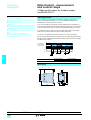
Dimensions
TWD LMDA 20D/K/20DRT/40D/K
b
Installation rules
1
a
20
80
90
20
80
80
20
4,5
20
a
TWD LMDA 20DTK/DUK 35.4
TWD LMDA 20DRT
47.5
TWD LMDA 40DTK/DUK 47.5
b
0 (excluding connector)
14.6
0 (excluding connector)
Important:
# Horizontal or flat mounting not permissible.
# Avoid placing devices which generate heat (transformers, power supplies, power
contactors...) beneath the controller.
Connections
TWD LMDA 20DTK
(1)
(2)
TWD LMDA 20DUK
TWD LMDA 20DRT
(2)
(1)
(1)
(2)
5 The COM (+) and COM (-) terminals are interconnected internally.
5 The COM and COM (+), COM and COM (-) terminals are independent.
5 The -V and +V terminals are interconnected internally.
TWD LMDA 40DTK
TWD LMDA 40DUK
(1)
(2)
(2)
(1)
(1)
(2)
(2)
(1)
5
5
5
5
Connectors CN1 and CN2 are independent.
The COM (+) and COM (-) terminals are interconnected internally.
The COM and COM (+), COM and COM (-) terminals are independent.
The -V and +V terminals are interconnected internally.
5 Output channels 0 and 1 are of the source transistor
type.
Output channels 2 to 7 are of the relay type.
5 The COM terminals are independent.
(1) Supply connection for sink inputs (positive logic).
(2) Supply connection for source inputs (negative logic).
1/15
Selection guide
1
Twido programmable controller
Discrete I/O modules
Applications
Discrete I/O modules
Type
8 $ 24 V inputs
Connection
Removable screw terminal block
1
Inputs
Outputs
Voltage ranges
$ 20.4...28.8 V
Input current
7 mA per point
Input logic
Sink/source (1)
Commons
1 common point
Response time
5 Energisation
5 De-energisation
4 ms
4 ms
16 $ 24 V inputs
32 $ 24 V inputs
HE 10 connector
5 mA per point
2 common points
Output types
Voltage range
Commons
Output current
5 Per output
5 Per group of channels
Isolation
Between channels : common point,
Between bus and channels : by photocoupler
I/O module type
TWD DDI 8DT
Page
1/16
TWD DDI 16DT TWD DDI 16DK TWD DDI 32DK
1/22
(1) Sink input : positive logic, source input : negative logic.
1
1
Discrete mixed I/O modules
1
Master module for AS-Interface bus
1
4 $ 24 V inputs/4 relay outputs
16 $ 24 V inputs/8 relay outputs
Removable screw terminal block
Non-removable spring terminal block
# For controller versions ≥ 2.0
# Management of slave modules:
5 Discrete: maximum of 62 slaves arranged in 2
banks, A/B, of 31 addresses each
5 Analogue: maximum of 7 slaves in bank A
# The AS-Interface M3 profile supports analogue
profile 7.3 (7 slaves), but does not support
analogue profile S-7.4
$ 20.4...28.8 V
7 mA per point
Sink/source
1 common point
4 ms
4 ms
1 N/O contact
" 240 V, $ 30 V
1 common point
2 common points
2 A (Ith)
7 A (Ith)
Between input channels : common point, between output channels : common point
Between bus and channels : by photocoupler
TWD DMM 8DRT
1/22
TWD DMM 24DRF
TWD NOI 10M3
1/33
1/17
Selection guide (continued)
1
Twido programmable controller
1
Discrete I/O modules
Applications
8/16 output modules with removable screw terminal block
Type
8 $ 24 V transistor outputs
Connection
Removable screw terminal block
1
Inputs
8 relay outputs
16 relay outputs
Voltage range
Input current
Input logic
Commons
Response time
5 Energisation
5 De-energisation
Outputs
Output types
Transistor
Relay with 1 N/O contact
Voltage range
$ 20.4...28.8 V
" 240 V, $ 30V
Logic (1)
Sink
Commons
1 common point
2 common points
Output current
5 Per output
5 Per group of channels
0.3 A nominal
3 A at 28.8 V
2 A max.
7 A max.
Isolation
Between channels: common point
Between bus and channels: by photocoupler.
Between channels: common point.
Between bus and channels: " 1500 V for
1 minute.
Output module type
TWD DDO 8UT TWD DDO 8TT TWD DRA 8RT TWD DRA 16RT
Page
1/18
Source
–
1/22
(1) Source output : positive logic, sink output : negative logic.
8 A max.
1
1
16/32 output modules with HE 10 connectors
1
16 $ 24 V transistor outputs
16 $ 24 V transistor outputs
32 $ 24 V transistor outputs
32 $ 24 V transistor outputs
Source
Sink
Source
HE 10 connector
Transistor
$ 20.4...28.8 V
Sink
1 common point
2 common points
0.1 A nominal
1 A at 28.8 V
Between channels: common point.
Between bus and channel: by photocoupler.
TWD DDO 16UK
TWD DDO 16TK
TWD DDO 32UK
TWD DDO 32TK
1/22
1/19
Twido programmable controller
Presentation,
description
1
Discrete I/O modules
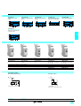
Presentation
1
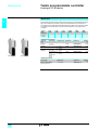
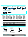
The range of Twido I/O modules includes input modules, output modules and mixed
input/output modules. With the 14 I/O modules offered, in addition to the I/O
integrated in 24 I/O compact base controllers and modular base controllers,
configurations can be adapted to best suit application requirements, so optimising
costs. The following discrete I/O modules are available :
# 4 $ 24 V discrete input modules comprising an 8-channel module, two
16-channel modules and a 32-channel module, equipped with either removable
screw terminal blocks or HE 10 type connector, depending on the model. These
modules can be either “sink or source”.
# 8 discrete output modules comprising two output modules with 8 and 16 relay
outputs, three output modules with 8, 16 or 32-channel "sink" transistor outputs and
three output modules with 8, 16 or 32-channel "source" transistor outputs, equipped
with either removable screw terminal blocks or HE 10 type connector, depending on
the model.
# 2 discrete mixed input and output modules, comprising one 4-channel input/
4-channel relay output module with removable screw terminal block and one
16-channel input/8-channel relay output module with non-removable spring terminal
block.
The narrow width of these I/O modules (17.5 mm, 23.5 mm, 29.7 mm or 39.1 mm)
makes it possible to build Twido configurations of up to 264 I/O with a minimal overall
size of L 255.4 mm x H 90 mm x D 81.3 mm.
All these discrete I/O modules and the analogue I/O modules are connected to the
base controller by stacking them on a DIN rail, starting from the right-hand side panel
of the base controller, according to the following rules :
5 For the 24 I/O compact base controller TWD LCAA 24DRF: 4 modules max. (see
characteristics page 1/6).
5 For 20 I/O modular base controllers TWD LMDA 20D/K: 4 modules max.
(see characteristics page 1/13).
5 For 20 and 40 I/O base controllers TWD LMDA 20DRT/40D/K: 7 modules max.
(see characteristics page 1/13).
All the discrete I/O modules are electrically isolated with the use of a photocoupler
between the internal electronic circuit and the input/output channels.
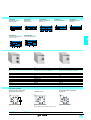
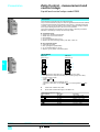
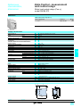
Description
Twido discrete I/O modules comprise :
4
1
1 An extension connector for electrical connection to the previous module (1).
2 One or two blocks for displaying the channels and module diagnostics.
3 One or two connection components of varying type, depending on the model :
5 removable screw terminal block (1 or 2) for modules whose reference ends in T,
5 HE 10 connector (1 or 2) for modules whose reference ends in K,
5 non-removable spring terminal block for module TWD DMM 24DRF.
4 Latching mechanism for attachment to the previous module.
2
3
Module with
removable screw
terminal block
Module with
HE 10 connector
These modules are mounted on a symmetrical DIN rail. Fixing kit TWD XMT 5
(supplied in lots of 5) allows plate or panel mounting. For modules with removable
screw terminal block, the terminal blocks are supplied with the module.
(1) A connector on the right-hand side panel ensures continuity of the electrical link with the next
I/O module.
1/20
1
Characteristics
1
Twido programmable controller
1
Discrete I/O modules
General characteristics
Temperature
Relative humidity
Degree of protection
Altitude
Vibration resistance
°C
Mounted on rail
Plate or panel mounted
(using fixing kit
TWD XMT5)
Shock resistance
m
Hz
m/s2
Hz
m/s2
Operation : 0…+ 55. Storage : - 25…+ 70.
30 to 95 %, without condensation
IP 20
Operation : 0…2000. Storage : 0…3000.
10…57, amplitude 0.075 mm, acceleration 57…150 Hz
9.8 (1 gn)
2…25, amplitude 1.6 mm, acceleration 25…100 Hz
39.2 (4 gn)
m/s2
147 (15 gn) for 11 ms
1
Characteristics of $ input channels
Module type
Number of input channels
Rated input voltage
Connection
Commons
Input voltage range
Rated input current
Input impedance
Filter time
Isolation
Internal consumption
for all inputs
TWD
V
V
mA
kΩ
ms
ms
At state 1
At state 0
At state 1
At state 0
$5V
$ 24 V
$5V
mA
mA
mA
DDI 8DT
DDI 16DT
8
16
$ 24 sink/source
Removable
screw terminal block
DDI 16DK
16
DDI 32DK
32
HE 10 connector
DMM 8DRT
4
DMM 24DRF
16
Removable
Spring
screw terminal terminal
block
block
1
1
2
$ 20.4...28.8
7
5
7
3.4
4.4
3.4
4
4
No isolation between channels, isolation with internal logic by photocouplers
25
40
35
65
25 (1)
0
20 (1)
5
10
5 (1)
65 (1)
45 (1)
10 (1)
Characteristics of transistor output modules
Module type
Number of output channels
Output logic (2)
Connection
Commons
Nominal output values Voltage
Current
Output voltage range
Voltage
Current per channel
Current per common
Response time
At state 1
At state 0
Residual voltage (voltage at state 1)
Maximum inrush current
TWD
V
A
V
A
A
µs
µs
V
A
DDO 8UT
DDO 8TT
8
Sink
Source
Removable screw terminal block
1
24
0.3
20.4…28.8
0.36
3
300
300
1 max
1
Leakage current
Overvoltage protection
mA
V
0.1
39
Maximum power of filament lamp
Isolation
Consumption
At state 1
for all the outputs
W
8
No isolation between channels, isolation with internal logic by photocouplers
10
10
20
20
40
70
5
5
10
At state 0
$5V
$ 24 V
$5V
mA
mA
mA
DDO 16UK
DDO 16TK
16
Sink
Source
HE 10 connector
DDO 32UK
32
Sink
DDO 32TK
Source
2
0.1
0.12
1
Characteristics of relay output channels
Module type
Number of output channels
Output currents
Current per channel
Current per common
Minimum switching load
Contact resistance (when new)
Loads (resistive, inductive)
TWD
rms insulation voltage
Consumption
for all the outputs
V
mA
mA
mA
At state 1
At state 0
$5V
$ 24 V
$5V
A
A
mA
mΩ
A
DRA 8RT
DRA 16RT
DMM 8DRT
DMM 24DRF
8 N/O contacts
16 N/O contacts
4 N/O contacts
8 N/O contacts
2
7
8
7
0.1/0.1 $ V (reference value)
30 max
2A/" 240 V or 2A/$ 30 V (with 1800 operations/hour max) :
- electrical life : minimum 100 000 operations
- mechanical life : minimum 20 x 106 operations
"1 500 for 1 minute
30
45
See values above (input channels)
40
75
See values above (input channels)
5
5
See values above (input channels)
(1) Consumption values are indicated for all inputs/outputs at state 0 or at state 1.
(2) Source output : positive logic, sink output : negative logic.
1/21
Twido programmable controller
References
1
1
Discrete I/O modules
References
These discrete I/O modules are mounted on symmetrical DIN rails to the right of the
Twido base controller. The maximum number of discrete and/or analogue I/O
modules which may be mounted depends on the type of base controller:
1
Type of
TWD base
Number of
modules
LCAA
10DRF
0
LCAA
16DRF
0
LCAA
24DRF
4
LMDA
20D/K
4
LMDA
20DRT
7
LMDA
40D/K
7
Discrete input modules
Input voltage
No. of
channels
$ 24 V
sink/source
TWD DDI 8DT
TWD DDI 32DK
8
No. of
common
point
1
16
1
32
2
Connection
Reference
Weight
kg
Removable
screw terminal
block (supplied)
Removable
screw terminal
block (supplied)
HE 10
connector
HE 10
connector
TWD DDI 8DT
0.085
TWD DDI 16DT
0.100
TWD DDI 16DK
0.065
TWD DDI 32DK
0.100
Discrete output modules
Type of output
Transistor
$ 24 V/0.3 A
Transistor
$ 24 V/0.1 A
TWD DDO 8/T/DRA 8RT
TWD DDO 16/K
Relay 2 A (Ith)
" 230 V/$ 30 V
No. of
channels
8, sink
No. of
common
point
1
8, source
1
16, sink
1
16, source
1
32, sink
2
32, source
2
8 (N/O
contact)
2
16 (N/O
contact)
2
Connection
Reference
Weight
kg
Removable
screw terminal
block (supplied)
Removable
screw terminal
block (supplied)
HE 10
connector
HE 10
connector
HE 10
connector
HE 10
connector
Removable
screw terminal
block (supplied)
Removable
screw terminal
block (supplied)
TWD DDO 8UT
0.085
TWD DDO 8TT
0.085
TWD DDO 16UK
0.070
TWD DDO 16TK
0.070
TWD DDO 32UK
0.105
TWD DDO 32TK
0.105
TWD DRA 8RT
0.110
TWD DRA 16RT
0.145
Connection
Reference
Discrete mixed input/output modules
TWD DDO 32/K
TWD DRA 16RT
No. of No. and
I/O
type of
inputs
8
4 I, $ 24 V
sink/source
24
No. and
No. of
type of
common
outputs
point
4 O, relay
Inputs :
(N/O contact) 1 common
2 A (Ith)
Outputs :
1 common
16 I, $ 24 V 8 O, relay
Inputs :
sink/source (N/O contact) 1 common
2 A (Ith)
Outputs :
2 commons
Weight
kg
Removable
TWD DMM 8DRT
screw terminal
block (supplied)
0.095
Non-removable TWD DMM 24DRF
spring terminal
block
0.140
Separate component
Description
TWD DDM 8DRT
TWD DDM 24DRF
Type
Wiring system TwidoFast,
Telefast
TWD module
compatibility
DDI 16/32DK
DDO 16/K/32/K
Reference
See page 1/38
Weight
kg
–
Replacement parts
Description
Type
10 contacts
Screw
terminal blocks
(sold in
lots of 2)
11 contacts
1/22
TWD module
compatibility
DDI /DT
DRT /RT
DDO 8/T
DMM 8DRT
Reference
TWD FTB 2T10
Weight
kg
–
TWD FTB 2T11
–
Dimensions,
connections
Twido programmable controller
1
1
Discrete I/O modules
Dimensions
Discrete I/O modules
c
70
a
90
TWD
DDI 8DT/16DT
DDI 16DK
DDI 32DK
DDO 8UT/8TT
DDO 16UK/16TK
DDO 32UK/32TK
DRA 8RT/16RT
DMM 8DRT
DMM 24DRF
a
23.5
17.6
29.7
23.5
17.6
29.7
23.5
23.5
39.1
c
14.6
11.3
11.3
16.6
11.3
11.3
14.6
14.6
1.0
4,5
Connections
$ 24 V input modules
TWD DDI 8DT
TWD DDI 16DK
(1)
(2)
(1)
(2)
(1)
(2)
5 The COM terminals are linked internally.
TWD DDI 16DT
5 The COM terminals are linked internally.
TWD DDI 32DK
(1)
(2)
(1)
(2)
5 The COM terminals are linked internally.
(1)
(2)
(1)
(2)
(1)
(2)
5 The COM0 terminals are linked internally.
5 The COM1 terminals are linked internally.
(1) Source input (negative logic)
(2) Sink input (positive logic)
1/23
1
Connections (continued)
1
Twido programmable controller
Discrete I/O modules
Transistor output modules
1
TWD DDO 8UT
TWD DDO 8TT
Fu
Fu
TWD DDO 16UK
Fu
TWD DDO 16TK
Fu
TWD DDO 32UK
Fu
Fu
Fu
1/24
Fu
TWD DDO 32TK
Fu
Terminals :
5 COM (-) are linked internally.
5 COM0 (-) are linked internally.
5 COM1 (-) are linked internally.
5 + V are linked internally.
5 + V0 are linked internally.
5 + V1 are linked internally.
Fu
Fu
Fu
Fu
Fu
Terminals :
5 COM (+) are linked internally.
5 COM0 (+) are linked internally.
5 COM1 (+) are linked internally.
5 - V are linked internally.
5 - V0 are linked internally.
5 - V1 are linked internally.
1
Connections (continued)
1
Twido programmable controller
1
Discrete I/O modules
Relay output modules
TWD DRA 8RT
TWD DRA 16RT
1
Fu
Fu
(1)
(2)
(1)
(2)
(1)
(2)
(1)
(2)
(3)
(4)
(3)
(4)
Terminals :
5 COM0 are linked internally.
5 COM1 are linked internally.
5 COM0 and COM1 are independent
(1) Sink output (negative logic)
(2) Source output (positive logic)
Mixed input/output modules
TWD DMM 8DRT
TWD DMM 24DRT
Fu
(1)
(2)
Fu
(3)
5 The COM (+) terminals are linked internally
(4)
(1)
(2)
5 Terminals COM0, COM1 and COM2 are independent
5 Terminals - V are linked internally.
(1) Source input (negative logic)
(2) Sink input (positive logic)
(3) Sink output (negative logic)
(4) Source output (positive logic)
1/25
Selection guide
1
Twido programmable controller
Analogue I/O modules
Applications
Analogue input modules
Analogue output modules
Number of I/O
2 inputs
1 output
Type
Voltage/current
Connection
Removable screw terminal block
1
Inputs
Outputs
Range
0...10 V (non differential)
4...20 mA (differential)
Resolution
12 bits (4096 points)
Acquisition period
32 ms + 1 controller cycle time
Range
0...10 V
4...20 mA
Resolution
12 bits (4096 points)
Transfer time
20 ms + 1 controller cycle time
External supply
$ 24 V external power supply to sensors/preactuators (voltage range 20.4...28.8 V)
Isolation
Isolation between channels and earth : by photocoupler
Analogue I/O module type
TWD AMI 2HT
Pages
1/30
1/26
TWD AMO 1HT
1
1
Analogue mixed I/O modules
1
Master module for AS-Interface bus
1
2 inputs/1 output
Voltage/current
Thermocouple/temperature probe inputs
Voltage/current output
0...10 V (non differential)
4...20 mA (differential)
Thermocouple type K, J and T
Pt 100 3-wire temperature probe
# For controller versions ≥ 2.0
# Management of slave modules:
5 Discrete: maximum of 62 slaves arranged in
2 banks, A/B, of 31 addresses each
5 Analogue: maximum of 7 slaves in bank A
# The AS-Interface M3 profile supports analogue
profile 7.3 (7 slaves), but does not support
analogue profile S-7.4
12 bits (4096 points)
32 ms + 1 controller cycle time
100 ms + 1 controller cycle time
TWD AMM 3HT
TWD ALM 3LT
1/30
TWD NOI 10M3
1/33
1/27
Presentation,
description
Twido programmable controller
1
Analogue I/O modules
Presentation
1
Twido analogue I/O expansion modules enable the acquisition of various analogue
values encountered in industrial applications, such as :
#
#
#
#
High-level inputs (voltage 0…10 V or current 4…20 mA).
High-level outputs (voltage 0…10 V or current 4…20 mA).
Low level inputs from thermocouples type K, J and T.
Low level inputs from 3-wire Pt 100 temperature probes, range -100...500 °C.
Analogue output modules are used to control the preactuators in devices such as
variable speed drives, valves and applications that require process control. The
output current or the voltage is proportional to the numerical value defined by the
user program. When the Twido controller stops, the outputs can be configured with
fallback (reset to the lowest scale value or hold the last value received). This function,
when set to “hold”, is useful when debugging the application or when a fault occurs,
in order not to disturb the process being controlled.
The 4 following analogue I/O modules are available :
# One module with 2 high-level inputs.
# One module with 1 high-level input.
# One mixed module with 2 inputs and 1 high-level output.
# One mixed module with 2 thermocouple or temperature probe inputs and 1 highlevel output.
All Twido analogue extension modules offer 12-bit resolution (4096 points) with
connection by removable screw terminal block. An external $ 24 V power supply is
required for each analogue module.
Like discrete I/O modules, analogue I/O modules are connected to the base
controller by stacking them on a DIN rail, starting from the right-hand side panel of
the base controller, according to the following rules :
# For 24 I/O compact base controller TWD LCAA 24DRF : 4 modules max. (see
characteristics page 1/6).
# For 20 I/O modular base controllers TWD LMDA 20D/K : 4 modules max. (see
characteristics page 1/13).
# For 40 I/O modular base controllers TWD LMDA 20DRT/40D/K : 7 modules max.
(see characteristics page 1/13).
All analogue I/O modules are electrically isolated with the use of a photocoupler
between the internal electronic circuit and the input/output channels.
Description
Twido analogue I/O modules comprise :
4
1
2
1 An extension connector for electrical connection to the previous module (1).
2 A block for displaying the channels and module diagnostics.
3 A removable screw terminal block for connection of the $ 24 V external power
supply, the sensors and the preactuators.
4 A latching mechanism for attachment to the previous module.
These modules are mounted on a symmetrical DIN rail. Fixing kit TWD XMT 5
(supplied in lots of 5) allows plate or panel mounting.
3
(1) A connector on the right-hand side panel ensures continuity of the electrical link with the next
I/O module.
1/28
Characteristics
1
Twido programmable controller
Analogue I/O modules
General characteristics
Temperature
Relative humidity
Degree of protection
Altitude
Vibration resistance
°C
Mounted on rail
Plate or panel mounted
(using fixing kit
TWD XMT5)
Shock resistance
m
Hz
m/s2
Hz
m/s2
Operation : 0…+ 55. Storage : - 25…+ 70.
30 to 95 %, without condensation
IP 20
Operation : 0…2000. Storage : 0…3000.
10…57, amplitude 0.075 mm, acceleration 57…150 Hz
9.8 (1 gn)
2…25, amplitude 1.6 mm, acceleration 25…100 Hz
39.2 (4 gn)
m/s2
147 (15 gn) for 11 ms
1
Analogue input characteristics
Module type
Number of channels
Range
TWD AMI 2HT/AMM 3HT
2 high-level inputs
Voltage
Current
0…10 V
4…20 mA
Type
Resolution
LSB value
Non differential
4096 points (12 bits)
2.5 mV
Connection
Permissible continuous overload
External supply
Input impedance
Max. sampling duration
Sampling repetition time
Acquisition period
Measuring precision
Max. error at 25° C
Removable screw terminal block
$ 13 V
40 mA
–
Rated voltage : $ 24. Voltage range : $ 20.4…28.8
1 MΩ min
10 Ω
250 Ω max
5 Ω max
16
50
16
50
32 + 1 controller cycle time
100 + 1 controller cycle time
± 0.2
0.2 + precision of cold ± 0.2
junction compensation
(± 4° C max)
± 0.006
± 0.5
Temperature coefficient
Repeat accuracy after
stabilisation time
Non linearity
Total error
Common mode rejection
Cross talk
Cabling
Dielectric strength
Type of protection
Consumption
V
ms
ms
ms
% PE
% PE/°C
% PE
% PE
% PE
V rms
mA
TWD ALM 3LT
2 low-level inputs
Thermocouple
Type K (0…1300° C)
Type J (0…1200° C)
Type T (0…400° C)
Temperature probe
Pt probe,
3-wire type
(- 100…500° C)
Differential
4 µA
0.325° C (type K)
0.3° C (type J)
0.1° C (type T)
0.15° C
± 0.2
±1
- 50 dB
2 low significance bits max.
Twisted shielded pair recommended
–
" 500 between the input and the supply circuit
Photocoupler between the input and the internal circuit
$ 5 V internal supply : 50. $ 24 V external supply : 40
Analogue output characteristics
Module type
Number of channels
Range
Resolution
LSB value
Load impedance
Applicable load
Stabilisation time
Total output system
transfer time
External supply
Measuring precision
Cabling
Dielectric strength
Consumption
(for TWD AMO 1HT)
ms
ms
TWD AMO 1HT/AMM 3HT/ALM 3LT
1 output
Voltage
0…10 V
4096 increments (12 bits)
2.5 mV
2000 min
Resistive
20
20 + 1 controller scan time
V
% PE
% PE/°C
% PE
Rated voltage : $ 24. Voltage range : $ 20.4…28.8
± 0.2
± 0.015
± 0.5
% PE
% PE
±1
± 0.2
1 low significance bit max.
±1
Twisted shielded pair recommended
" 500 between the input and the supply circuit
50
40
Ω
Max. error at 25 °C
Temperature coefficient
Repeat accuracy after
stabilisation time
Output error
Non linearity
Output ripple
Total error
$ 5 V internal supply
$ 24 V external supply
% PE
V rms
mA
mA
Current
4…20 mA
4 µA
300 max
1/29
References
1
Twido programmable controller
Analogue I/O modules
References
1
These analogue I/O expansion modules are mounted on symmetrical DIN rails to the
right of the Twido base controller. The sensors/preactuators are connected to a
removable screw terminal block (supplied with each module). The maximum number
of analogue I/O modules which may be mounted depends on the type of base
controller :
Type of
TWD
controller
Number of
modules
LCAA
10DRF
LCAA
16DRF
LCAA
24DRF
LMDA
20D/K
LMDA
20DRT
LMDA
40D/K
0
0
4
4
7
7
Analogue I/O modules
Channel
type
2 inputs
1 output
2 inputs and
1 output
TWD AMI 2HT
TWD ALM 3LT
Input range
Output range
Resolution
Reference
0…10 V
4…20 mA
–
–
12 bits
TWD AMI 2HT
12 bits
TWD AMO 1HT
0.085
12 bits
TWD AMM 3HT
0.085
12 bits
TWD ALM 3LT
0.085
0…10 V
4…20 mA
0…10 V
0…10 V
4…20 mA
4…20 mA
Thermocouple 0…10 V
K, J, T
4…20 mA
Temperature
probe
Pt 100
Weight
kg
0.085
Replacement part
Description
Screw terminal block
(Sold in packs of 2)
1/30
Application
Reference
11 contacts
TWD FTB 2T11
Weight
kg
–
Twido programmable controller
Dimensions,
connections
1
Analogue I/O modules
Dimensions
Analogue I/O modules
1
3,8 23,5
90
4,5
Connections
Input module TWD AMI 2HT
Voltage/current
sensor
Output module TWD AMO 1HT
Voltage/current
preactuator
Voltage/current
sensor
# Fit a fuse of appropriate size for the sensor type.
# Do not connect any wires to the unused channel.
# Fit a fuse of appropriate size for the preactuator type.
# Do not connect any wires if the channel is unused.
Mixed input/output module TWD AMM 3HT
Mixed input/output module TWD ALM 3LT
Voltage/current
preactuator
Voltage/current
sensor
Voltage/current
preactuator
Pt 100
temperature probe
Thermocouple K, J, T
Voltage/current
sensor
# Fit a fuse of appropriate size for the sensor and preactuator types.
# Do not connect any wires to unused channels.
# Fit a fuse of appropriate size for the sensor and preactuator types.
# For a Pt 100 3-wire temperature probe (RTD), connect the three wires to
terminals A , B’ and B (channels IN0 and IN1).
# For a Pt 100 2-wire temperature probe (RTD), connect the two wires to
terminals A and B’ and make a bridge between B' and B (channels IN0 and
IN1).
# For a thermocouple, connect the two wires to the + and - terminals
(channels IN0 and/or IN1).
# Do not connect any wires to unused channels.
1/31
Twido programmable controller
Presentation,
description
1
1
Master module for AS-Interface bus
Presentation
Master module TWD NOI 10M3 for AS-Interface bus allows the Twido controller
(versions 4 2.0) to perform the function of AS-Interface master.
1
Twido controller
+ Master module
TWD NOI 10M3
Indicator
bank
Power
Sensors
AS-Interface bus
Control
station
Safety
monitor
Safety
interface
XBL
keypad
Motor starter
The bus consists of a Master station (Twido controller) and Slave stations. The
Master, which supports the AS-Interface profile, polls each of the devices connected
to the AS-Interface bus, in turn, and stores information gathered (sensor/actuator
status, operating status of the devices) in the controller memory. Communication on
the AS-Interface bus is managed in a way that is totally transparent to the Twido
application program.
The TWD NOI 10M3 master module manages the following with the AS-Interface M3
profile:
5 discrete slave modules (maximum of 62 slaves arranged in 2 banks, A and B, of
31 addresses each),
5 analogue slaves (maximum of 7 slaves in bank A).
The AS-Interface M3 profile supports analogue profile 7.3 (7 slaves), but not
analogue profile S-7.4.
The maximum number of TWD NOI 10M3 modules per Twido controller is 2.
7 discrete, analogue and AS-Interface I/O modules are controlled by TwidoSfot
software, see page 1/40.
An AS-Interface power supply is essential to supply the various modules on the bus.
It should preferably be located close to the stations with high power consumption. For
more information on power supplies, see pages 1/8 and 1/14.
Description
Module TWD NOI 10M3 takes the form of a standard-size module. It is connected to
a Twido base controller (compact or modular) in the same way as any I/O module.
6
1
4
5
2
3
7
It comprises:
1 A display block comprising:
# 6 pilot lights indicating the module operating modes:
5 green PWR pilot light: module powered up,
5 red FLT pilot light: error in the configuration loaded,
5 green LMO pilot light: module in local mode,
5 green CMO pilot light: module in connected mode,
5 red CNF pilot light: not used,
5 red OFF pilot light: module in protected, unconnected mode.
# 6 green pilot lights, 3 for inputs, 3 for outputs.
2 A block for displaying the status of the addresses.
3 Two pushbuttons PB1 and PB2 for controlling the status of the slaves by selecting
their address and changing the mode.
4 An extension connector for electrical connection to the previous module.
5 A connector (on the RH side) for I/O expansion modules TWD D// and TWD A//
(4 or 7 depending on version).
6 A latching mechanism for attachment to the previous module.
7 A power supply removable screw terminal block.
TWD NOI 10M3 master module connections
Brown wire
As-Interface flat cable
Blue
1/32
Diagnostics,
characteristics,
references
Twido programmable controller
1
Master module for AS-Interface bus
1
Diagnostics
The 30 pilot lights on the front panel of the module are used in conjunction with the
two pushbuttons for diagnostics by the Twido controller.
The display block on the front panel of master module TWD NOI 10M3 allows
simplified local diagnostics to be performed by displaying the slaves present on the
AS-Interface bus.
Software set-up
The AS-Interface bus is configured using TwidoSoft software, see pages 1/40 to 1/47.
The services offered are based on the principle of simplicity:
5 Management of profile tables, parameters and data by the master (management
transparent to the user).
5 Topological addressing of I/O: any AS-Interface slave defined on the bus has a
topological address assigned to it on the bus, in a way that is transparent to the user.
5 Each AS-Interface module sensor/actuator is seen by the Twido programmable
controller in the same way as any “In-rack" I/O.
General characteristics
Module type
AS-Interface profile
Type of addressing
Product certifications
Degree of protection
Altitude
Temperature
Relative humidity
Degree of pollution
Immunity to corrosion
Vibration
Mounted on rail
resistance
Plate or panel mounted
(using fixing kit TWD XMT5)
Shock resistance
As-Interface external power supply
Internal current
At $ 5 V
At $ 24 V
AS-Interface consumption at $ 24 V
m
°C
Hz
Hz
m/s2
$V
mA
mA
mW
TWD NOI 10M3
AS-Interface M3 , V 2.11 (profile S-7.4 not supported)
Standard and extended
AS-Interface n° 47801
IP 20
Operation: 0…2000; Transport: 0…3000
Operation: 0…+ 55; Storage: - 25…+ 70
30 to 95 % (without condensation)
2 conforming to IEC 60664
Free of corrosive gases
10…57, amplitude 0.075 mm,
57…150 (acceleration: 9.8 m/s2); for 2 hours on all 3 axes
2…25, amplitude 1.6 mm,
25…100 (acceleration: 39.2 m/s2); for 90 minutes on all 3 axes
147 (15 gn) duration 11 ms, on all 3 axes
29.5…31.6
80
0
540
Communication characteristics
As-Interface bus
cycle time
With 1 to 19 slaves
With 20 to 62 slaves
With 31 standard slaves or slaves in banks A & B
With 62 slaves in banks A and B
Analogue modules (1)
Max. no. of
modules
Discrete modules (1)
Max. no. of I/O
Standard slaves
Slaves in banks A and B
Max. length of
Without splitter block or extension
AS-Interface cable With a total of 2 splitter blocks or extensions
AS-Interface bus voltage
ms
ms
ms
ms
m
m
$V
3
0.156 x (1 + N) where N = number of active slaves
5
10
7
62
248 = 124 inputs + 124 outputs
434 = 248 inputs + 186 outputs
100
300
30
References
Description
AS-Interface master module
for Twido programmable
controllers V 4 2.0
Number
Protocol/profile Number of I/O
per controller
(1)
2
AS-Interface/M3 63 discrete modules max.
7 analogue modules max.
Reference
TWD NOI 10M3
Weight
kg
0.085
Connection accessories
Description
Flat cable for
AS-Interface bus (yellow)
TWD NOI 10M3
Length
Reference
20 m
50 m
100 m
XZ CB 10201
XZ CB 10501
XZ CB 11001
Weight
kg
1.400
3.500
7.000
(1) When analogue and discrete modules are connected simultaneously to the network, the analogue modules use addresses 1 to 31 in bank A. When an analogue
module uses a certain address, the module addresses having the same number in bank B cannot be occupied for slaves in banks A/B.
1/33
1
Twido programmable controller
Presentation,
description
1
Communication
Presentation
In order to communicate with an intelligent environment, Twido compact and modular
programmable controllers offer an RS 485 serial communication port on the module
as well as an optional type RS 485 or RS 232 link.
These two ports allow Twido compact and modular controllers to use four
communication protocols: Programming, Modbus, ASCII, and Remote link.
1
Description
Compact base controllers have the following on the front panel:
1 An RS 485 serial port, with mini-DIN type connector for connection to the
programming terminal.
2 A slot for fitting a 2nd optional port (RS 485/RS 232) using TWD NAC ///
adapters.
1
2
or
TWD NAC
485D/232D
3
Compact base
controller
TWD NAC
485T
4
1
Modular base controllers have the following on the front panel:
1 An RS 485 serial port, with mini-DIN type connector for connection to the
programming terminal.
The slot for fitting a 2nd optional port (RS 485/RS 232) using adapters TWD NAC ///
is located behind the removable cover 2 of a TWD NOZ //// interface module 3 or
a TWD XCP ODM display module 4.
The interface and display modules connect to the left-hand side of modular base
controllers.
Twido controller communication ports
or
Serial port
RS 485
mini-DIN
Optional port (2nd port)
RS 485
RS 232
mini-DIN
mini-DIN
Compact
base
controllers
All compact
base controllers
TWD LCAA ////
TWD NAC 485 D
(1)
TWD NAC 232 D
(2)
RS 485
screw
terminal block
TWD NAC 485 T
(1)
Modular
base
controllers
All modular
base controllers
TWD LMDA ////
TWD NOZ 485 D
(1)
or
TWD XCP ODM +
TWD NAC 485D
TWD NOZ 232 D
(2)
or
TWD XCP ODM +
TWD NAC 232D
TWD NOZ 485 T
(1)
or
TWD XCP ODM +
TWD NAC 485T
+
2
TWD NOZ //// TWD XCP ODM
or
TWD NAC
485D/232D
Modular base
controller
TWD NAC
485T
(1) With max. cable length: 200 m.
(2) With max. cable length: 10 m.
If the RS 232 physical layer is used for a length greater than 10 metres, use the
RS 485 physical layer and an RS 485/RS 232 conversion module reference
XGS Z24.
Connection
Serial link
RS 485
8
7
6
4
5
2
3
1
Optional link
RS 485D
8
7
6
4
5
2
3
1
RS 232 D
8
7
6
4
5
2
RS 485T
3
A
B
SG
1
TWD LCAA ////
TWD NAC 485D
TWD NAC 232D
TWD NAC 485T
TWD LMDA ////
TWD NOZ 485D
TWD NOZ 232D
TWD NOZ 485T
1 A+
A A+
A+
RTS
2 BB BBDTR
3 NPC
SG 0 V
NC
TXD
4 /DE
NC
RXD
5 /DPT
NC
DSR
6 NPC
NC
0V
7 0V
0V
0V
8 5 V (180 mA)
5 V (180 mA)
5 V (180 mA)
NC: not connected
NPC: do not connect
/DPT: 1 = master; If not connected, the PUNIT protocol is used for communication with PCs (at
state 1, 19200 bauds, with no parity); If connected to 0 V, the communication parameters are
those configured by the TwidoSoft software.
1/34
1
Twido programmable controller
References,
dimensions
1
1
Communication
References
Serial link modules and adapters
Description
Serial interface adapters
Compatibility
Physical layer
Connection
Reference
Compact base controllers
TWD LCAA 16/24DRF
Built-in display module
TWD XCP ODM
RS 232C
Mini-DIN
connector
Mini-DIN
connector
Screw terminals
TWD NAC 232D
Weight
kg
0.010
TWD NAC 485D
0.010
TWD NAC 485T
0.010
Mini-DIN
connector
Mini-DIN
connector
Screw terminals
TWD NOZ 232D
0.085
TWD NOZ 485D
0.085
TWD NOZ 485T
0.085
RS 485
TWD NAC 232D/485D
Serial interface modules
Modular base controllers
TWD LMDA 20/40D//
RS 232C
RS 485
TWD NAC 485T
Digital display and built-in display module
Description
Built-in display module
Compatibility
Characteristics
Reference
Modular base controllers
TWD LMDA 20/40D//
Mounted on left-hand side
of base controller.
Enables adjustment and diagnostics
of the programmable controller.
Can take a serial adapter
TWD NAC ////
TWD XCP ODM
Weight
kg
0.105
Connection accessory
TWD NOZ ///
Description
Serial link
connection cable
Link
from
to
Serial interface adapter
Modbus module
or RS 485 serial interface (RJ 45 connector)
module
(mini-DIN connector)
Length
Reference
3m
TWD XCA RJ030
Weight
kg
0.160
Modems
Description
TWD XCP ODM
PSTN modem: type WESTERMO TD-33 / V.90,
supplied with a telephone cable (length 3 m)
GSM modem: type WAVECOM WMOD2B dual band
900/1800 Mhz, supplied with a power cable
(length 1.5 m) and clips for plate mounting
Accessory kit for GSM modem comprising:
a modem cable (length 0.5 m), an antenna with cable
(length 3 m), and accessories for mounting on rail
Supply voltage
Reference
$ 12/36 V
SR1 MOD01
Weight
kg
0.231
$ 24 V
SR1 MOD02
0.127
–
SR1 KIT02
0.180
Dimensions
Modules TWD NOZ ////XCP ODM
70
a
13,9
90
4,5
TWD NOZ ////
TWD XCP ODM
a
22.50
38
1/35
1
Twido programmable controller
Presentation,
characteristics
1
Communication protocols
Programming protocol
1
Link by modem
1 Remote programming PC.
2 Cable TSX PCX 1031 on serial port.
3 Modem for transmitting/receiving data.
4 Telephone or radio link.
5 Twido compact or modular controller.
3
1
4
3
2
5
1
Link by cable
1 Programming PC.
2 Cable TSX PCX 1031 RS 485 on serial port or USB cable TSX PCX 3030 for
Windows 2000 or XP.
3 Twido compact or modular controller.
2
3
Characteristics
Protocol type
Data rate
Physical layer
Connection
Compatibility
Kbit/s
Programming
19.2
RS 485
Serial port
With compact base controllers TWD LCAA //// and
modular base controllers TWD LMDA ////
Modbus protocol
1
2
3
Modbus bus
5
6
4
8
8 7
9
Twido controller connected directly on the Modbus bus
1 Magelis compact display XBT N40/.
2 Cable XBTZ 978 on serial port.
3 Cable for optional RS 485 port.
4 Twido modular controller.
5 Modbus hub LU9 GC3.
6 Modbus tap link cable VW3 A8 306 R//.
7 Line end adapters VW3 A8 306 RC.
8 Modbus T-junctions VW3 A8 306 TF// (with cables).
9 Twido compact controller.
10 Modules: ATS 48 and ATV 28.
7
6
10
Characteristics
Protocol type
Data rate
Data bits
Stop bits
Parity
Physical layer
Connection
Compatibility
1/36
Kbit/s
Modbus
1.2…38.4
Initial value: 19.2
7 or 8
Initial value: 8
1 or 2
Without, even or odd
Initial value: without
RS 485/RS 232 (point-to-point)
Serial port (RS 485) or optional port (RS 485/RS 232)
Compact base controllers TWD LCAA //// and
modular base controllers TWD LMDA ////
1
Twido programmable controller
Presentation,
characteristics
1
1
Communication protocols
ASCII protocol
3
1
4
3
2
7
Link by modem
1 Simple ASCII display.
2 Standard RS 485 cable or cable TSX PCX 1031 for RS 232 conversion, on serial
port.
3 Modem for transmitting/receiving data.
4 Telephone or radio link.
5 Twido compact or modular controller.
6 ASCII printer.
7 Standard RS 485/RS 232 cable on optional port.
5
6
3
4
3
Link by cable
1 Simple ASCII display.
2 Standard RS 485 cable or cable TSX PCX 1031 for RS 232 conversion, on serial
port.
3 Twido compact or modular controller.
4 Standard RS 485/RS 232 cable on optional port.
5 ASCII printer.
1
2
3
4
5
Characteristics
Protocol type
Data rate
Kbit/s
Data bits
Stop bits
Parity
Physical layer
Connection
Compatibility
ASCII
1.2…38.4
Initial value: 19.2
7 or 8
Initial value: 8
1 or 2
Initial value: 1
Without, even or odd
Initial value: without
RS 485/RS 232
Serial port (RS 485) or optional port (RS 485/RS 232)
With compact base controllers TWD LCAA //// and
modular base controllers TWD LMDA ////
“Remote link” protocol
1
3
(1)
3
(1)
3
(1)
2
“Remote Link” decentralised I/O
Each compact or modular base controller can be extended by means of Twido base
controllers used either as an I/O extension, or as a local “reflex” controller.
5 When used as an I/O extension, these base controllers cannot take any I/O
extensions.
5 When used as a local “reflex” controller, these base controllers have their own
application program. Internal words are reserved for automatic exchange of
information between the base controllers.
1 Base controller.
2 RS 485 3-wire cable on serial port or on optional port.
3 Twido base controllers used as I/O extension or as local “reflex” controller.
(1) Connection is made either to the serial port, or to the optional port.
Characteristics
Protocol type
Data rate
Physical layer
Connection
Number of Twido modules that can be connected
Compatibility
Kbit/s
Remote link
38.4
RS 485
Serial port or optional port only.
from 1 to 7
With compact base controllers TWD LCAA //// and
modular base controllers TWD LMDA ////
1/37
1
Twido programmable controller
Presentation,
combinations
1
Pre-wired solutions
Presentation
Combinations of modular base controllers and I/O modules with HE 10 type connector
Combination
possible
Twido modules Base controller
12 inputs
8 outputs
TWD LMDA 20DTK/40DTK (6)
Type of connection block 26-way HE10
Not applicable
Extension modules
16 inputs
16 outputs
DDI 16DK/32DK (6) DDO 16TK/32TK (6) DDO 32UK/32DK
20-way HE10
With TwidoFast pre-formed cables
12 inputs and 8 outputs
16 inputs or 16 outputs
TWD FCW 30M/50M
TWD FCW 30K/50K
With TwidoFast kits (sub-bases + cables)
Telefast 2 mixed connection kits
12 inputs/8 outputs
TWD FST 20DR10/20DR20
Telefast 2 connection kits with passive sub-bases
16 inputs
TWD FST 16D10/16D20
Telefast 2 connection kits with relay sub-bases
16 outputs
TWD FST 16R10/16R20
With Telefast 2 and all necessary cables
Connection sub-bases
8 channels
12 channels
16 channels
ABF TP26MP/00
ABE 7H08R///7H08S21
ABE 7H12R///7H12S21
ABE 7H16R///H16C///7H16S21
ABE 7H16R23
ABE 7H16F43
ABE 7H16S43
ABF TE20EP/00 ABF TE20SP/00
(1)
(1)
(4)
(3)
(4)
(3)
Input adapter sub-bases
16 channels
ABE 7S16E2///7P16F3//
(3)
Output adapter sub-bases
8 channels
ABE 7S08S2///
ABE 7R08S////7P08T330
(5)
(1) (2)
16 channels
ABE 7R16S////7R16T////7P16T///
(4)
ABE 7S16S1///
(4)
ABE 7S16S2///
Sub-bases for analogue/counting I/O
ABE 7CPA01/7CPA02/7CPA03
ABE 7CPA21/7CPA31
(1) Using splitter sub-base ABE 7ACC02 which allows splitting of 16 channels into 2 x 8 channels (Twido/sub-base cable).
(2) For sub-base ABE 7R08S216 with 8 bistable relays, all 16 output channels are used.
(3) 12 input channels used out of 16 available.
(4) 8 output channels used out of 12/16 available.
(5) Except for sub-base ABE 7R08S216 with bistable relays which requires 16 output channels.
(6) Module with two connectors, requiring use of two identical cables.
Connections
1/38
1
2
3
4
5
6
7
8
9
10
11
12
13
14
15
16
17
18
19
20
20-way HE10 B
Output side
–
–
18
20
16
8
15
7
14
6
13
5
12
4
11
3
10
2
9
1
ABF TE20SP/00
26-way HE10 A
Twido side
1
2
3
4
5
6
7
8
9
10
11
12
13
14
15
16
17
18
19
20
20-way HE10 B
Input side
18
–
20
–
17
–
19
–
–
–
8
–
7
–
6
–
5
–
4
–
3
–
2
–
1
–
ABF TE20EP/00
26-way HE10 A
Twido side
–
20
–
12
–
11
–
10
–
9
–
8
–
7
–
6
–
5
–
4
–
3
–
2
–
1
26-way HE10 C
Output side
1
2
3
4
5
6
7
8
9
10
11
12
13
14
15
16
17
18
19
20
21
22
23
24
25
26
20-way HE10 B
Input side
ABF TP26MP/00
26-way HE10 A
Twido side
1
With its HE 10 connector products, the Twido range offers several solutions for economical, fast and reliable wiring.
# TwidoFast pre-formed cables, in 3 or 5 m lengths, have one end fitted with an HE 10 type connector and the other with referenced, free wires,
to facilitate the connection of inputs/outputs.
# Telefast 2 pre-wired kits which, under a single reference, include a TeleFast 2 sub-base together with its cable (1 or 2 m length) for connection
to the HE 10 connectors on Twido modules. These sub-bases allow easy wiring with their screw terminal blocks, as well as signal adaptation
(Twido transistor outputs to relay outputs, 1 common per 4 channels).
# Three types of cable, available in 3 lengths, which ensure compatibility with the entire Telefast 2 range, so allowing Twido controllers to be
used in conjunction with Telefast 2 sub-bases (see table below).
18
20
19
17
16
8
15
7
14
6
13
5
12
4
11
3
10
2
9
1
1
References
1
Twido programmable controller
1
Pre-wired solutions
References
TwidoFast pre-formed cables
Description
Pre-formed cables
HE10 female connector
(Sold in packs of 5)
Description
For use with
Twido
Modular base controllers
TWD LMDA
20DTK/40DTK
Gauge
C.s.a.
1 pre-formed
22
cable: one end
0.035 mm2
fitted with HE 10
22
connector, one end
0.035 mm2
with free wires
I/O extensions
22
TWD DDI 16DK/32DK 0.035 mm2
TWD DDO 16/K/32/K 22
0.035 mm2
26-way
–
–
20-way
–
–
Cable
length
3m
Reference
TWD FCW 30M
Weight
kg
0.405
5m
TWD FCW 50M
0.670
3m
TWD FCW 30K
0.405
5m
TWD FCW 50K
0.670
–
–
TWD FCN 5K26
TWD FCN 5K20
Cable
length
1m
Reference
TWD FST 16D10
Weight
kg
0.330
2m
TWD FST 16D20
0.410
1m
TWD FST 16R10
0.440
2m
TWD FST 16R20
0.520
1m
TWD FST 20DR10
0.570
2m
TWD FST 20DR20
0.650
–
–
TwidoFast kits (sub-bases + cables)
Description
16 inputs
16 outputs
TWD FST 16/0
12 inputs/8 outputs
Description
For use with
Twido
1 passive sub-base Inputs
1 pre-formed cable TWD DDI 16DK/32DK
Gauge
C.s.a.
22
0.035 mm2
22
0.035 mm2
1 relay sub-base
Outputs
22
1 pre-formed cable TWD DDO 16TK/32TK 0.035 mm2
22
0.035 mm2
1 passive sub-base Modular base controllers 22
1 relay sub-base
TWD LMDA
0.035 mm2
1 pre-formed cable 20DTK/40DTK
22
0.035 mm2
Telefast 2 connection cables (2)
Description
TWD FST 16R/0
Description
For use with
Gauge
Cable
Reference
Weight
Twido
C.s.a.
length
kg
Discrete I/O
1 pre-formed
Modular base controllers 28
1m
ABF TP26MP100
0.200
cable: one end
TWD LMDA
0.080 mm2
fitted with 26-way 20DTK/40DTK
28
2m
ABF TP26MP200
0.500
HE 10 connector
0.080 mm2
on Twido side, one
28
3m
ABF TP26MP300
0.800
end fitted with two
0.080 mm2
20-way HE 10
connectors on
Telefast 2 side
1m
ABF TE20EP100
0.080
Discrete inputs
1 pre-formed
Inputs
28
cable: one end
TWD DDI 16DK/32DK 0.080 mm2
fitted with 20-way
28
2m
ABF TE20EP200
0.140
HE 10 connector
0.080 mm2
on Twido side, one
28
3m
ABF TE20EP300
0.210
end fitted with
0.080 mm2
20-way HE 10
connector on
Telefast 2 side
1m
ABF TE20SP100
0.080
Discrete outputs
1 pre-formed
Outputs
28
cable: one end
TWD DDO 16TK/32TK 0.080 mm2
fitted with 20-way
28
2m
ABF TE20SP200
0.140
HE 10 connector
0.080 mm2
on Twido side, one
28
3m
ABF TE20SP300
0.210
end fitted with
0.080 mm2
20-way HE 10
connector on
Telefast 2 side
(1) Each station may be used as a decentralised I/O extension or as a local "reflex" programmable controller (with exchanges
of input/output words between the different stations).
(2) For further details of the Telefast 2 range, please refer to the specialist catalogue “Telefast 2 pre-wired system”.
1/39
1
Presentation
1
Twido programmable controller
TwidoSoft programming software
Presentation
1
TwidoSoft is a graphical development environment for creating, configuring and
managing applications for Twido programmable controllers. TwidoSoft is a 32-bit
Windows-based program which runs on a PC with Windows 98 (second edition),
2000 or XP operating system. TwidoSoft software is based on a standard interface
which offers the user-friendly features of the Windows environment with which users
are already familiar: windows, toolbars, pull-down menus, balloon tips, contextsensitive help, etc.
For development work, TwidoSoft provides a comprehensive set of features to
simplify programming and configuration:
5 Programming in instruction list or ladder language. These two languages are
reversible.
5 Application browser with multiple window views, aiding easy software
configuration.
5 Editors for main programming and configuration functions.
5 Cut, copy and paste functions.
5 Symbolic programming.
5 Cross-referencing.
5 Duplication of application programs.
On site (on-line mode), TwidoSoft provides the following main functions:
5 Real-time animation of program and/or data elements.
5 Diagnostics on programmable controller operation.
5 Monitoring of the application’s use of memory.
5 Downloading and uploading of controller programs.
5 Backup of controller programs to the optional EEPROM memory modules.
Connecting a PC to a Twido controller
# The PC is connected to the built-in serial port of the Twido controller by means of
a TSX PCX 1031 multifunction cable or to a USB port using cable TSX PCX 3030
(Windows 2000 or XP only). It converts RS 232 output signals from the PC to RS 485
signals for the controller.
Connection of a PC, via cable, to the built-in port of Twido base controllers
automatically sets the communication protocol of this port to a protocol which is
compatible with TwidoSoft.
# It is also possible to connect the PC to the serial port of Twido base controllers via
modems.
The modems used must be defined, for TwidoSoft via the "Preferences" screen, and
for the Twido controller, via the hardware configuration ("Connection management"
screen).
When the connection is established, TwidoSoft and the Twido controller will each
initialise the modem assigned to them by sending a initialisation string of the Hayes
protocol type.
1/40
1
Functions
1
Twido programmable controller
1
TwidoSoft programming software
User interface
User interface
TwidoSoft provides an intuitive, Windows-based user interface, including balloon tips
and on-line help. The Twido user interface offers the following features:
# Application browser: this browser is a window providing the directory structure of
the application. The windows and toolbars can be moved and attached to the borders
of the main window. The elements of an application appear in a logical hierarchy
based on their structure within the application. They are arranged as an indented tree
structure which can be expanded or collapsed. The application browser can be used
to view, program and manage a Twido application and to configure hardware using a
graphical representation of the base controllers, I/O extensions and options.
# Status bar: this is a panel at the bottom of the main window which displays
information about the application, the controller status and the TwidoSoft software
mode. This bar includes a "a memory usage indicator", indicating the percentage of
total memory used by the program. A warning message is displayed when available
memory is getting low.
# Operating modes: TwidoSoft software can operate in on-line mode (PC connected to
the Twido base controller) and off-line mode (PC disconnected from the Twido base
controller). Off-line mode is used to develop an application in the design office. This
application must then be transferred from the PC memory to the controller memory
(downloaded) in order to be able to run on the controller. On-line mode is used to debug
and adjust this application. In this mode, the application program in the PC memory is
identical to the application in the controller memory. Program changes can therefore be
made directly to the application in the Twido controller.
Editors and viewers
TwidoSoft provides special windows, called editors, for performing the main tasks
necessary to develop an application. A TwidoSoft application consists of a program,
configuration data, symbols allocated to the variables and documentation. These
components can be used in any order when creating an application.
Developing each part of an application using separate editors makes it possible to
rationalise the development process. TwidoSoft software provides:
# Instruction List language and Ladder language editors.
# A configuration editor.
# Variables editors (with symbols) and animation table editors.
# Ladder language, cross reference and program error viewers.
TwidoSoft software also provides security features to protect the integrity of
programs. "Application protection" right of access prevents access to the controller
application. This option prohibits unauthorised transfers of an application. Password
protection is selected when an application is transferred to the controller to make
access to the application secure.
Configuration of hardware and software
Configuring Twido programmable controllers consists of selecting options for the
controller’s hardware and software resources. These resources can be adapted at any
time while creating a program:
# Hardware resources allow the user to define the type and number of Twido
components in a configuration: base controller, remote controllers, I/O expansion
modules and optional modules.
# Software resources consist of configurable and non configurable functions. Function
blocks (also called variables) are blocks created in memory to execute automation
functions which will be used by the program. For example, when configuring a counter
function block, memory addresses in the controller are assigned to represent the values
associated with the parameters of this counter (current values, preset values). Other
software resources are called internal memory blocks, such as bits, words, constant
words, system words, network exchange words.
These resources are configured using TwidoSoft software.
1/41
1
Functions (continued)
1
Twido programmable controller
TwidoSoft programming software
Programming
Programming
1
TwidoSoft allows the user to write a controller program in either Ladder language or
instruction List language. The language selected depends on user preference and
does not affect the application:
# Ladder language consists of a series of ladder rungs, represented graphically,
together with text comments.
# Instruction List language consists of a series of text-based instructions.
In either language, the program is "written" in the logical order required to control the
machine or process. It is recommended that the programs be "documented" by
adding comments (explanatory text inserted at program instruction level).
These two languages are reversible, provided that a few basic rules are followed:
Ladder programming
A program written in Ladder language consists of networks of linked graphical
elements (similar to electromagnetic contact diagrams), organised into rungs which
are executed sequentially by the controller when it is in RUN mode.
Each rung comprises graphical elements (contacts, coils) linked by horizontal and
vertical "lines", organised into a programming grid starting with a potential bar on the
left and ending with a second potential bar on the right. The graphical elements are
associated with:
# Controller inputs and outputs, such as sensors, pushbuttons and relays.
# Arithmetic, logic and numeric value comparison operations.
# Automation function blocks, such as timers, counters, drum controllers, registers,
etc.
# Controller internal variables, such as internal bits and words.
Instruction List programming
A program written in instruction List language consists of a series of instructions
executed sequentially by the controller. Each instruction is represented by a single
program line and consists of three components:
# Line number - line numbers are generated automatically when the instructions are
entered.
# Instruction code - the instruction code is a symbol linked to an operand identifying
the operation to be performed on this operand. These operations are generally of the
Boolean and numerical type.
# Operand - an operand is a reference, a symbol or a number representing a piece
of physical data. For example, in the program opposite, the operand %I0.4 is the
reference corresponding to a controller discrete input.
Programmable controller variables
An instruction can include from zero to three operands, depending on the type of
instruction code. The operands may be:
# Sensor image inputs (detectors, control buttons, etc.)
# Preactuator output images (contactors, solenoid valves, pilot lights, etc.)
# Internal bits (equivalent to the internal relays in electromagnetic control
equipment)
# Control equipment function blocks (timers, counters, drum controllers, registers).
# ...
1/42
1
Functions (continued)
1
Twido programmable controller
1
TwidoSoft programming software
Integrated functions, software set-up
Integrated functions
PID
1
For all controller versions 4 2.0:
# 14 PID programming loops.
# "Autotuning" algorithm 1.
# Analogue / PWM output.
# Linear conversion of measuring input.
# 2 alarm levels (high and low) on the "measurement".
# Command output limits,
# Direct and inverse action.
# 2 animated modes for TwidoSoft PID:
5 configuration mode,
5 debugging mode.
Event processing
For all controller versions 4 2.0:
# Event management by the application.
# 2 priority levels.
# 3 types of source:
5 4 event sources based on the basic inputs,
5 4 event sources based on the very fast threshold counter (VFcounter),
5 1 event source based on the periodic event (Timer).
# Command masked and enabled by the system bits.
# Each event executes a single user logic subroutine.
# Updating of "reflex" outputs.
Software set-up
For all controller versions 4 2.0:
Configuration of the AS-Interface bus is carried out via TwidoSoft software, version
2.0 or greater. The services offered are based on the principle of simplicity:
# Management of profile tables, parameters and data by the master (management
transparent to the user).
# Topological addressing of I/O: any AS-Interface slave defined on the bus has a
topological address assigned to it on the bus, in a way that is transparent to the user.
# Each AS-Interface module sensor/actuator is seen by Twido in the same way as
any I/O.
Configuration of the AS-Interface bus
Configuration of all the modules present on the AS-Interface bus is carried out by
following the on-screen instructions:
Definition of the AS-Interface bus master module
Module TWD NOI 10M3 is defined like any I/O module.
Configuration of AS-Interface slave modules
From the definition screen, it is possible to configure all the slave modules
corresponding to all the I/O of the interfaces present on the AS-Interface bus.
The user selects the reference of the AS-Interface module shown in the Schneider
Electric catalogue, among the various discrete, analogue or safety modules. This
selection automatically determines the AS-Interface profile and parameters
associated with each interface module.
Programming
After configuration, the I/O connected to the AS-Interface bus are processed by the
application program in the same way as any of the PLCs "In-rack" I/O, either by their
address (e.g. %I\4.0\16.2, input 2 of slave 16 on the AS-Interface bus), or by their
associated symbol (e.g. Start_conveyor).
1 Available 1st half of 2004.
1/43
Functions (continued)
1
Twido programmable controller
1
TwidoSoft programming software
Integrated counter, positioning
Integrated counter function
The counter function allows the controller to count a large number of pulses, within one
program scan cycle. Using its integrated 16-bit fast counters, Twido can count up to
65 535 pulses generated by $ 24 V sensors. It can compare the current counter value
with a preset value and trigger an output when the preset value is reached. This type
of counter function can be used for counting parts or events, or for measuring length
or position .
The number of integrated fast-counters depends on the type of base controller:
1
Base controller type
TWD
Counter VFC (20 kHz)
Counter FC (5 kHz)
Compact
LCAA 10/12/24 DRF
1
3
Modular
LMDA 20D/K
2
2
Very fast counter - VFC (20 kHz)
The 20 kHz VFC (Very Fast Counter) is an up/down counter with possibility of auxiliary
inputs. The counter is accessed by means of a function block (%VFCi) programmed
using TwidoSoft. The %VFCi function block can be used to execute one of the following
5 functions, all with a maximum frequency of 20 kHz:
# Up/Down counter
# Up/Down counter with detection of running direction.
# Single Up counter.
# Single Down counter.
# Frequency meter.
The pulses to be counted may come from an incremental encoder or from 2 proximity
sensors (up/down counting) connected to inputs I0 and I1 of Twido base controllers.
Fast counter - FC (5 kHz)
The fast counter is available for up or down counting of pulses (rising edges) on the
discrete inputs of Twido base controllers, at a maximum frequency of 5 kHz. The Up
and Down counters are accessed by means of a function block (%VFCi)
programmed using TwidoSoft. Using the configuration editor, the user must select
either Up or Down counting mode for each function block, define the initial value of
the preset %FCi.P (1...65 535) and select the attribute "adjustable" in order to be
able to dynamically change the preset value %FCi.P and the current value %FCi.V.
Within function block %FCi, the current value %FCi.V varies by:
# Incrementing the value 0 to the preset value %FCi.P in counter mode.
# Decrementing the preset value %FCi.P to 0 in down counter mode.
Positioning
Twido modular controllers include two positioning functions (frequency 7 kHz) which
can be used, for example, for controlling step motors:
# Function PLS (pulse) - pulse generator output
# Function PWM - pulse width modulation output. This function can also be used for
applications with light or sound intensity control (controller function).
PLS function (pulse, 7kHz)
The PLS function block generates pulses of fixed ratio. In some cases, the frequency
can be fixed and in others it is variable (as in control of slopes when driving step
motors). The %PLS function block can be programmed to generate a specific
number of pulses.
%PLS function blocks are assigned to outputs %Q0.0.0 or %Q0.0.1 on modular base
controllers.
The pulse generator signal has a variable period, but with a constant duty cycle
which establishes an ON to OFF ratio of 50 % of the period (see illustration opposite).
PWM function (7 kHz)
The PWM function block generates pulses of fixed frequency, with a variable ratio between
the high state and low state of the output signal. The ON to OFF duration ratio is a dynamic
variable called %PWM.R, with a range from 0 % to 100 %.
PWM function blocks are assigned to outputs %Q0.0.0 or %Q0.0.1 on a base
controller. The PWM function can be used to control analogue module outputs.
The user-defined %PWM function block generates a signal on output %Q0.0.0 or
%Q0.0.1 of modular base controllers (see illustration opposite).
1/44
Characteristics
1
Twido programmable controller
1
TwidoSoft programming software
Characteristics
Instructions
Combinational List instructions
#
#
#
#
#
#
#
#
LD, LDN, LDR, LDF : read the state of a bit, (direct, inverse, rising and falling edges)
ST, STN, S, R : write an output (direct, inverse, set, reset)
AND, ANDN, ANDR, ANDF : logic AND with a bit (direct, inverse, rising and falling edges)
OR, ORN, ORR, ORF : logic OR with a bit (direct, inverse, rising and falling edges)
LD (, AND (, OR(,) : open and close brackets (8 possible levels)
XOR, XORN, XORR, XORF : exclusive OR with a bit
MPS, MRD, MPP : buffer memory management for divergence towards output bits
N : negation
Grafcet List instructions
#
#
#
#
#
#
#
-*-i : step (1 ≤ i ≤ 62)
=*=i : initial step (1 ≤ i ≤ 62)
#i : activate step i, after deactivation of current step
# : deactivate current step
#Di : deactivate step i after another step
=*=POST : start post-processing
%Xi : bit associated with step i
Instructions on program
#
#
#
#
#
#
MCS, MCR : master relay
END, ENDC, ENDCN : end of program (conditional or unconditional)
JMP, JMPC, JMPCN : jump to a label % L (conditional or unconditional)
SRn : call subroutine n (0 ≤ n ≤ 15)
RET : end of subroutine
NOP : non-operative instruction
List title and comments
# Title : 122 characters before each LD, LDN, LDR, LDF instruction
# Comments : 4 lines of 122 characters before each LD, LDN, LDR, LDF instruction
# Possibility of associating a comment of 122 characters with each instruction
Ladder rungs
# 10 contacts of 7 lines with 1 output per line
# Title : 122 characters per rung
# Comments : 4 lines of 122 characters
Ladder language graphical symbols
# Normally open, normally closed and on edge contacts
# Direct, inverse, SET and RESET coils
# Program jump, subroutine call
Standard function blocks (1)
#
#
#
#
#
Timers : %TMi (0 ≤ i ≤ 31) 0 to 9999 (word)
Up/Down counters : %Ci (0 ≤ i ≤ 15) 0 to 9999 (word)
4 16-bit LIFO or FIFO registers : %Ri (0 ≤ i ≤ 3)
4 Drum controllers : %DRi (0 ≤ i ≤ 3) 8 steps
Real-time clock : %RTCi (0 ≤ i ≤ 15) month, day, hour, minute.
Specific function blocks (1)
#
#
#
#
#
#
#
#
Transmission/reception of message of 64 words maximum (internal or constant) : EXCH
Exchange control : %MSG available output, fault output
8 shift bit registers : %SBRi (0 ≤ i ≤ 7), shift one step to the left or right (max. 16 steps)
8 step counter blocks : %SCi (0 ≤ i ≤ 7), move forward or back one step (max. 256 steps)
Fast counter (5 kHz ), Up/Down counter : )&
Very fast counter 20 kHz, Up/Down counter, frequency meter 9)&
Pulse width modulated output : %PWM with modular base controller
Pulse generator output : %PLS with modular base controller
Numerical instructions
#
#
#
#
#
#
Assignment in word, indexed word, word table bit strings : :=
Arithmetic : +, -, x, /, REM, SQRT
Logic : AND, OR, XOR, NOT, INC, DEC
Shift operation : SHL, SHR, ROL, ROR (logic and rotate)
Conversion : BTI, ITB (BCD <-> Binary)
Comparison: >, <, <=, >=, =, <>
Specific functions
#
#
#
#
1 input for controller RUN/STOP command
1 Security output : controller "block" error
Real time display of Grafcet steps used
Symbol table management
Arithmetic functions with variables
#
#
#
#
#
#
#
#
+, -, *, /
SQRT
ABS
TRUNC
LOG
LN
EXP
EXPT
(1) When the numbers of objects are not indicated, see characteristics pages 1/6 and 1/12
1/45
1
Characteristics (continued)
1
Twido programmable controller
TwidoSoft programming software
Characteristics (continued)
1
Instructions (continued)
Trigonometrical functions with variable
#
#
#
#
#
#
#
#
COS
SIN
TAN
ACOS
ASIN
ATAN
DEG_TO_RAD
RAD_TO_DEG
Double word functions
#
#
#
#
#
#
#
#
#
#
+, -, *, /
SQRT
ABS
REM
INC
DEC
SHL
SHR
ROL
ROR
Other functions
#
#
#
#
#
#
#
#
#
#
#
#
SUM_ARR
EQUAL_ARR
FIND_EQR_FIND_GTR, FIND_LTR
MAX_ARR, MIN_ARR
OCCUR_ARR
SORT_ARR
ROR_ARR, ROL_ARR
LENGTH_ARR
L_KUP
MEAN
ITB, BTI
DINT_TO_REAL, REAL_TO_DINT
Bit objects (1)
#
#
#
#
#
#
% I/Qx.y : I/O bits
% Mi : internal bits
% Si : 128 system bits
%Xi : 62 Grafcet steps
% //i.j : function block bits
% //i:Xk : bits extracted from internal words, system words, constant words, input and output
words
Word objects (1)
#
#
#
#
#
% MWi : internal words
% KWi: 64 constant words
% SWi : 128 system words
% INWi.j : 4 input words per controller (exchange words for inter-controller communication)
% QNWi.j : 4 output words per controller (exchange words for inter-controller
communication)
Bit string and word table objects
# %/i:L : bit strings (I/O, internal, system and Grafcet bits)
# %/Wi:L : word tables (internal, constant and system words)
Addressable objects
(1) When the numbers of objects are not indicated, see characteristics pages 1/6 and 1/12
1/46
1
References
1
Twido programmable controller
1
TwidoSoft programming software
References
The multi-language software packages (English, French, German, Italian and
Spanish) are for use on PCs (1) with Windows 98 SE , Windows 2000 and Windows
XP operating system.
These software packages include:
# A CD-ROM containing TwidoSoft multi-language software and multi-language
documentation for hardware and software set-up.
# Depending on the model, a PC/Twido controller connection cable, reference
TSX PCX 1031 which is compatible with Twido, Micro and Premium programmable
controllers (length 2.5 m).
TwidoSoft software packages
Description
Reversible
languages
TwidoSoft
Ladder
multi-language Instruction List
packs
PC
connection cable
TSX PCX 1031
Reference
Weight
(1)
kg
TWD SPU 1001 V10M
–
Without
TWD SPU 1002 V10M
–
Separate components
Description
Connecting
cables
Application
From
All
Twido controllers
Reference
To
USB port on the PC (2) TSX PCX 3030
with TwidoSoft
software installed
Serial port on the PC TSX PCX 1031
with TwidoSoft
software installed
Weight
kg
–
–
TwidoPack kits
Schneider Electric offers two TwidoPack kits to help you discover and become
familiar with the new range of Twido programmable controllers. TwidoPack, which is
inexpensive and easy to use, is available in two versions, each comprising:
# A Twido base controller.
# A set of options.
# A TwidoSoft software package (with cable) TWD SPU 1001 V10M.
# A teach-yourself E-Learning CD-Rom.
Description
TwidoPack
Compact
TwidoPack
Modular
Twido base
controller
Compact 10 I/O
TWD LCAA 10DRF
" 100…240 V,
relay outputs
Modular 20 I/O
TWD LMDA 20DTK
$ 24V supply,
transistor outputs
Options
Reference
(3)
TWD XDP PAK1/
Weight
kg
–
Real-time clock
TWD XDP PAK2/
cartridge
TWD XCP RTC
Built-in display module
TWD XCP ODM
Serial interface adapter
TWD NAC 485T
Pre-formed cable (3 m)
TWD FCW 30M
–
Real-time clock
cartridge
TWD XCP RTC
6-input simulator
TWD XSM 6
User documentation
Description
Twido
installation
and set-up
manuals
Hardware and
software
Format
Language
Reference
Hard copy
(216 x 181 mm)
English
TWD USE 10AE
Weight
kg
–
French
TWD USE 10AF
–
German
TWD USE 10AD
–
Spanish
TWD USE 10AS
–
Italian
TWD USE 10AI
–
(1) Typical recommended configuration: 300 MHz processor, 128 Mb of RAM with 40 Mb of
available hard disk space.
(2) PC running under Windows 2000 or XP operating system only.
(3) Replace the / at the end of the reference with E: English, F: French.
1/47
1
3
2/0
-
Contents
0
2 - Zelio Relay - plug-in relays
Selection guide for control relays and plug-in control relays
# Universal relays . . . . . . . . . . . . . . . . . . . . . . . . . . . . . . . . . . . . . . . . . . . . page 2/5
# Miniature relays . . . . . . . . . . . . . . . . . . . . . . . . . . . . . . . . . . . . . . . . . . . . page 2/8
# Interface relays . . . . . . . . . . . . . . . . . . . . . . . . . . . . . . . . . . . . . . . . . . . page 2/11
2
2/1
Selection guide
Applications
2
Zelio Relay - plug-in relays
Equipment based on control relays
Control relays
Mini-control relays
"
12…690 V
12…690 V
24…400 V
$
12…440 V
12…250 V
12…72 V
/
/
/
–
–
/
/
–
–
–
/
–
–
–
–
2
Control
voltages
Functions
Instantaneous relays
On-delay or Off-delay relays
Latching relays
Pulse on energisation relays
Flashing relays
/ Function performed
Low consumption version for $
Features
Version with alternating contacts
Linked contacts (in accordance with INRS and BIA specifications)
–
–
Number of
contacts
On basic device
5 N/O or 3 N/O + 2 N/C combined
double break
4 N/C or N/O combined
double break
2 N/C or N/O combined
double break
On auxiliary contact blocks
Up to 4 N/C or N/O contacts combined 4 N/C or N/O combined
double break
double break
2 N/C or N/O combined
double break
Conventional thermal current
10 A
Operational voltage
Up to 690 V
Up to 660 V
Up to 690 V
Durability (operating cycles)
1 A/230 V, AC-15
30 million
2 million
10 million
30 million
6 million
10 million
Device type
CAD
CA/-K
CA/-SK
Pages
Please consult our catalogue “Motor starter solutions”
1 A/24 V, DC-13
2/2
2
2
2
Equipment based on plug-in control relays
Plug-in control relays
Universal type plug-in control relays Miniature plug-in control relays
Interface relays
2
12…240 V
24…230 V
(other voltages available on request)
24 or 48 V
(other voltages available on request)
24…230 V
(other voltages available on request)
12, 24, 48 or 110 V
(other voltages available on request)
24…240 V
/
/
/
/
/
/
/
–
/
/
/
–
–
–
–
/
–
–
–
–
Low consumption as standard for $
Manual override of contact operation possible, by means of actuator
–
–
Version with LED to indicate relay status
–
Version with low level contacts
(gold flashed contacts)
–
–
Other functions and connections available on request
4 C/O (Off-delay, On-delay)
2 or 3 C/O (Off-delay, On-delay)
2 or 4 C/O (Offdelay, On-delay)
2, 3 or 4 C/O (Off- 1 or 2 C/O (Off-delay, On-delay)
delay, On-delay)
–
–
–
–
–
5A
10 A (RUN-21 and RUN-31)
4 A (RUN-33)
5 A (RXN-21)
6 A (RXL-4)
10 A (RXL-3)
12 A (RXL-2)
8 A (RSB-2A080//)
12 A (RSB-1A120//)
16 A (RSB-1A160//)
5…240 V
–
6, 12, 24, 48, 60 or 110 V
Version with gold- –
flashed contacts
Up to " 400 V/$ 300 V
Up to 250 V
400 000
500 000
100 000
100 000
100 000
–
–
–
–
–
RH
RU
RXN
RXL
RSB
(1)
2/5
(1) Please consult your Regional Sales Office.
2/8
2/11
2/3
Characteristics
2
Zelio Relay - plug-in relays
2
Universal relays
Relay type
RUN 21C
RUN 31C
RUN 21D
RUN 31A
RUN 33A
3 C/O
2 C/O
3 C/O
3 C/O linked
Hard silver 10 µ gold-flashed
4
36 000
3600
10
"250, $125
1
1000
Contact characteristics
Number and type of contacts
Contact materials
Rated thermal current (Ith)
Maximum operating rate
In operating cycles/h
2 C/O
AgNi
A
10
36 000
3600
V
20
V
"/$ 250
mA 50
VA 3000
For temperature 6 40 °C
No-load
Under load
Minimum
Maximum
Minimum
Maximum
Switching voltage
Breaking capacity
10
36 000
3600
20
"/$ 250
50
3000
Coil characteristics
Rated voltage (Un)
Average consumption
Inrush
Sealed
"
$
"
V
V
VA
Permissible voltage variation
Drop-out voltage threshold
24, 48, 110, 230, 50/60 Hz (other voltages available on request)
12, 24, 48, 110 (other voltages available on request)
3.5
"2.3 VA, $1.5 W
0.8…1.1 Un (50 Hz or $), 0.85…1.1 Un (60 Hz)
≥ "0.15 Un, ≥ $0.05 Un
Environment
Conforming to standards
Product certifications (pending)
Ambient air temperature
around the device
Vibration resistance
Degree of protection
Shock resistance
Mechanical durability
Operating time
(response time)
Electrical durability
In millions of operating cycles/h
Standard version
Standard version
Storage
°C
Operation
°C
Conforming to IEC EN 68-2-6
EN 61810-1
UL, CSA
- 40…+ 70
"- 20…+ 40, $- 20…+ 60
4 gn (30…100 Hz)
IP 40
10 gn
In millions of operating cycles
20
Between coil energisation "
ms About 15
and making of the
ms About 15
$
On-delay contact
ms About 15
Between coil de"
energisation and making $
ms About 15
of the Off-delay contact
Resistive load
≥ 0.1 to 10 A
Inductive load
See curves below
Insulation characteristics
Rated insulation voltage (Ui)
Insulation class
Dielectric strength
(rms voltage)
Conforming to IEC 947
Conforming to VDE 0110
Between coil and contact "
Between poles
Between contacts
"
V
V
V
V
Durability in N (230 V, 50 Hz)
Durability (number of operating cycles)
10 7
6
4
3
2
1,5
1
5x10 6
2x10 6
10 6
2
5x10 5
1
1 Resistive load
2 Inductive load
10 5
10 20
1
2
3
0,6
0,4
0,3
0,2
2x10 5
5x10 4
250
C 250, B 380
2500
2500
1000
Switching capacity on a $ supply for minimum durability of : 106 operating cycles
(resistive or inductive load with diode RVW 040BD)
10 3
5x10 3 VA
50 10 2
2x10 2
2x10 3
Switching capacity
1 Contact
2 Contacts in series
3 Contacts in series
0,1
0 20
Socket type
60
RUZ 1A
100
140
200
RUZ 1D
RUZ 1C
RUZ 7A
RUZ 7D
RUN 21D
RUN 21C
RUN 31C
RUW type E2
RUN 31A
RUN 33A
RUN 21D
Socket characteristics
Conventional rated thermal current (Ith)
A
Insulation class
Degree of protection
Product certifications
Connection
Solid cable without cable end
Flexible cable with or w/o cable end
Arrangement of coil/contact terminals
Type of protection module
Relay types used
References :
page 2/5
2/4
Dimensions :
page 2/15
10
C 250
IP 20
CSA, UR
2 x 2.5 mm2
2 x 1.5 mm2
Mixed
–
RUN 31A
RUN 33A
Schemes :
page 2/13
References
2
Zelio Relay - plug-in relays
2
Universal relays
560592
Relays for standard applications
Number
of C/O
contacts
2
Conventional
rated thermal
current
A
10
LED
Pins
Without
Octal
8 flat pins
Octal
8 flat pins
Undecal
11 flat pins
Undecal
11 flat pins
Green
3
10
Without
Green
RUN 31C22// + RUZ 1C
Sold in Unit reference, to Weight
lots of be completed by
adding the control
voltage code (1)
kg
10
RUN 21D21//
0.105
10
RUN 21C21//
0.110
10
RUN 21D22//
0.105
10
RUN 21C22//
0.110
10
RUN 31A21//
0.105
10
RUN 31C21//
0.110
10
RUN 31A22//
0.105
10
RUN 31C22//
0.110
Relays with gold-flashed contacts
3
4
Green Undecal
10
RUN 33A22//
0.105
LED indicator modules (2)
Type
560593
Description
"Power on"
indication
–
Voltage
Sold in Unit reference
lots of
Weight
V
" 110…230
$ 6/24
With protection diode
20
20
RUW 010P7
RUW 030BD
kg
0.006
0.006
$ 6…230
" 24
" 230
" 110…240
20
20
20
20
RUW 040BD
RUW 042B7
RUW 042P7
RUW 041P7
0.006
0.006
0.006
0.006
7 24…240
1
RUW 101MW
0.020
Protection modules (2)
Diode
Varistor
E2
E2
E2
E2
RC circuit
Timer module (2)
Multifunction
–
Sockets
RUN 31A21// + RUZ 1A
Protection
module
Relay type
560594
Without module RUN 21 octal
(indicator,
RUN 31 and RUN 33
protection or
undecal
timer)
RUN 21C and
RUN 31C
RUN 31A and
With module
RUN 33
(indicator,
protection or
RUN 21 octal
timer)
I/O
Sold in Unit reference
lots of
Weight
Mixed
Mixed
10
10
RUZ 1D
RUZ 1A
kg
0.067
0.067
Mixed
10
RUZ 1C
0.067
Mixed
10
RUZ 7A
0.069
Mixed
10
RUZ 7D
0.069
Accessories
Description
560590
RUN 33A22// + RUW 101MW + RUZ 7A
Sold in Unit reference
lots of
Weight
kg
Maintaining clamp for octal/undecal
25
RUZ 200
0.001
Maintaining clamp for flat pin
25
RUZ 210
0.001
(1) Standard control circuit voltage. For other voltages, please consult your Regional Sales Office.
Volts
12
24
48
110
230
$
RUN 21 and RUN 31 JD
BD
ED
FD
–
RUN 33
–
BD
ED
–
–
" 50/60 Hz
RUN 21, RUN 31
–
B7
E7
F7
P7
and RUN 33
(2) Modules for use with sockets RUZ 7A or RUZ 7D.
Coil characteristics
Control
circuit
voltage Uc
RUZ 200
V
12
24
48
110
230
Characteristics :
page 2/4
Dimensions :
page 2/15
d.c. supply
Average
resistance
at 20 °C
± 10%
Ω
96
384
1336
7660
–
Cod. Operating
voltage limits
Min.
Max.
JD
BD
ED
FD
–
V
9.6
19.2
38.4
88
–
V
19.2
26.4
52.8
121
–
a.c. supply 50/60 Hz
Average
Cod. Operating
resistance
voltage limits
at 20 °C
Min.
Max.
± 15 %
Ω
V
V
–
–
–
73.7
B7 204
26.4
305
E7 408
54.8
1710
F7 93.5
121
7500
P7 196
253
Schemes :
page 2/13
2/5
Characteristics
2
Zelio Relay - plug-in relays
2
Miniature relays
Relay type
RXL 2A12B///
RXL 3A10B///
RXL 4A06B///
2 C/O
AgNi
12
3 C/O
4 C/O
10
6
5
2500
5
1500
RXL 4G06B///
Contact characteristics
Number and type of contacts
Contact materials
Conventional rated
thermal current (Ith)
Maximum operating rate
In operating cycles/h
Switching voltage
Breaking capacity
AgNi/AU 5 µ
For temperature 6 40 °C
A
No-load
Under load
Minimum
Maximum
Minimum
Maximum
18 000
1200
V
5
V
"250, $250
mA 5
VA 3000
2
1500
Coil characteristics
"
$
"
$
Rated voltage (Un)
Average consumption
Permissible voltage variation
Drop-out voltage threshold
V
V
VA
W
24…230, 50/60 Hz
12…110
1.6
0.9
0.8…1.1 Un (50/60 Hz or $)
≥ 0.15 Un
≥ 0.1 Un
"
$
Environment
Conforming to standards
Product certifications (pending)
Ambient air temperature
around the device
Vibration resistance
Degree of protection
Shock resistance
Mechanical durability
Operating time
(response time)
Electrical durability
In millions of operating cycles/h
Standard version
Standard version
Storage
Operation
Conforming to IEC 68-2-6
IEC 61810-1
UL, CSA
°C - 40…+ 85
°C $ - 40…+ 70, " - 40...+ 55
> 5 gn (10…150 Hz)
IP 40
10 gn (closing), 5 gn (opening)
≥ 20
In millions of operating cycles
Between coil energisation "
ms About 12
and making of the
$
ms About 12
On-delay contact
Between coil de"
ms About 12
energisation and making $
ms About 4
of the Off-delay contact
12 A - 250 V : ≥ 0.1 10 A - 250 V : ≥ 0.1
Resistive load
See curves below
Inductive load
≥ 20
6 A - 250 V : ≥ 0.1
Insulation characteristics
Conforming to IEC 947
Conforming to VDE 0110
Between coil and contact "
Between poles
Between contacts
"
250
C 250
V
2500
V
2500
V
1500
Reduction coefficient for inductive load
(depending on power factor cos ϕ)
Reduction coefficient
Number of operating cycles
Electrical durability of contacts
Resistive load "
V
107
C
106
B 250
2000
Breaking capacity on a resistive load $
Current $
Rated insulation voltage (Ui)
Insulation class
Dielectric strength
(rms voltage)
1
0,8
0,6
12
10
5
4
3
2
C
1
0,4
0,5
0,4
0,3
D
A
0,2
A
B
105
0
1
2
3
Switching capacity
A RXL 4
B RXL 2
C RXL 3
References :
pages 2/8 and 2/9
2/6
B
0,1
1 0,8 0,6
0,4
0,3
RXL 2, RXL 3 et RXL 4
0,2
Cos ϕ
0 20 30 80 120 160 200 250 300
Voltage $
A RXL 3 (T = 0 ms)
B RXL 3 (T = 40 ms)
C RXL 4
D RXL 2
Durability (inductive load) = durability (resistive load) x reduction coefficient
Dimensions :
page 2/14
Schemes :
page 2/12
Characteristics (continued)
2
Zelio Relay - plug-in relays
2
Miniature relays
Relay type
RXN 21E1///
RXN 41G1///
Contact characteristics
Number and type of contacts
Contact materials
Rated thermal current (Ith)
Maximum operating rate
In operating cycles/h
For temperature 6 40 °C
No-load
Under load
Minimum
Minimum
Maximum
Switching voltage
Breaking capacity
2 C/O
AgNi
A
5
18 000
1200
V
Minimum: 5, maximum: 250 " , 250 $
mA 10
VA 1250
4 C/O
Coil characteristics
Rated voltage (Un)
Average consumption
Permissible voltage variation
Drop-out voltage threshold
$12…110, "24…230, 50/60 Hz
$0.9 W, "1.6 VA
0.8…1.1 Un (50/60 Hz or $)
$≥ 0.1 Un, "≥ 0.15 Un
V
Environment
Conforming to standards
Approvals (pending)
Ambient air temperature
around the device
Standard version
Standard version
Storage
Operation
Conforming to IEC 68-2-6
IEC 61810-1
CSA, UL
°C - 40…+ 70
°C - 20…+ 50
> 5 gn (30…150 Hz)
IP 40
20 gn
In millions of operating cycles
20
Between coil energisation "
ms About 12
and making of the
ms About 12
$
On-delay contact
ms About 12
Between coil de"
energisation and making $
ms About 4
of the Off-delay contact
Resistive load
5 A / 250 V : ≥ 0.1
Inductive load
See curves below
Vibration resistance
Degree of protection
Shock resistance
Mechanical durability
Operating time
(response time)
Electrical durability
In millions of operating cycles/h
Insulation characteristics
Conforming to IEC 947
Conforming to VDE 0110
Between coil and contact "
Between poles
Between contacts
"
107
Durability (number of operating cycles)
250
A 250
V
2000
V
2000
V
1500
Reduction coefficient for inductive load
(depending on power factor cos ϕ)
Reduction coefficient
Electrical durability of contacts
Resistive load "
V
106
1
0,8
Breaking capacity on a resistive load $
5
4
3
Current $
Rated insulation voltage (Ui)
Insulation class
Dielectric strength
(rms voltage)
0,6
2
1
0,7
0,5
0,4
0,3
0,4
0,2
0,1
105
0 20 40 60 80
0
1 0,8 0,6
1
2
Switching capacity (kVA)
0,4
0,2
Cos ϕ
120 160 200
250
Voltage $
Durability (inductive load) = durability (resistive load) x reduction coefficient
RXZ
E1S108M E1S111M E1S114M E1M114M E1M114
Socket type
7G
Socket characteristics
Conventional rated thermal current (Ith)
A
Insulation class
Degree of protection
Product certifications
Connection
Solid cable without cable end
Flexible cable with or w/o cable end
Arrangement of coil/contact terminals
Type of protection module
Relay types used
12
C 250
IP 20
CSA, UR
2 x 2.5 mm2
2 x 1.5 mm2
Separate
RZM type E
RXL 2
RXL 3
RXN 21
(1) Limited to 7 A in operation.
References :
pages 2/8 and 2/9
Dimensions :
page 2/14
12
7
6
2 x 1.5 mm2
2 x 2.5 mm2
Mixed
RXL 4
RXN 4
RXL 4
RXN 4
–
RXW type L
RXL 2 (1), RXN 21 RXN 21
RXL 4, RXN 41
RXN 41
Schemes :
page 2/12
2/7
References
2
Zelio Relay - plug-in relays
2
Miniature relays
560586
References
Relays for standard applications (1)
Number of
C/O contacts
Conventional rated
thermal current
A
5
2
12
3
10
4
5
RXN 21E12BD + RXZ E1M114
108780-26-s
6
LED
Sold in
lots of
Unit reference,
to be completed
by adding the
control voltage
code (2)
Weight
Red
Without
Green
Without
Green
Without
Red
Without
Green
Without
10
10
10
10
10
10
10
10
10
10
RXN 21E12//
RXN 21E11//
RXL 2A12B2// RXL 2A12B1//
RXL 3A10B2//
RXL 3A10B1//
RXN 41G12//
RXN 41G11//
RXL 4A06B2//
RXL 4A06B1//
kg
0.035
0.034
0.036
0.035
0.036
0.035
0.035
0.034
0.036
0.035
10
10
RXL 4G06B2//
RXL 4G06B1//
0.036
0.035
Sold in
lots of
Unit reference
10
RXW 040MD
kg
0.010
RZM 040W
RZM 031RB
RZM 031BN
RZM 031FPD
RZM 021RB
RZM 021BN
RZM 021FP
RZM 041BN7
RZM 041FU7
0.003
0.004
0.004
0.004
0.005
0.005
0.005
0.010
0.010
Relays with gold-flashed contacts (1)
4
6
With
Without
Protection modules for sockets RXZ 7G
Description
Diode
Type
Voltage
L
V
$ 12…250
Weight
Protection modules for relay/sockets RXZ E////M
560588
RXL 4A06B1BD + RXZ E1S114M
Diode
Diode +
green LED
E
Varistor +
green LED
E
RC circuit
E
$ 6…230
$ 6…24
$ 24…60
$ 110…230
$ or "6…24
$ or "24…60
$ or "110…230
" 24…60
" 110…240
10
10
10
10
10
10
10
10
10
(2) Standard control circuit voltages
Volts
12
24
48
$
JD
BD
ED
" (50/60 Hz)
RXN
–
B7
E7
RXL
–
B7
E7
For other voltages, please consult your Regional Sales Office.
110
FD
F7
–
120
–
–
F7
230
–
P7
P7
Coil characteristics
RXL 2A12B2BD + RXZ P20 + RXZ E1S108M
560589
2/8
d.c. supply
Average
Cod. Operating voltage
resistance
limits
at 20 °C
Min.
Max.
± 10%
Ω
V
V
a.c. supply 50/60 Hz
Average
Cod. Operating voltage
resistance
limits
at 20 °C
Min.
Max.
± 15 %
Ω
V
V
V
RXN relays
12
160
JD 9.6
13.2
–
–
–
–
24
640
BD 19.2
26.4
150
B7 19.2
26.4
48
2600
ED 38.4
52.8
635
E7 38.4
52.8
110
13 600
FD 88
121
–
F7 –
–
230
–
–
–
–
15 400
P7 184
253
RXL relays
12
160
JD 9.6
13.2
–
–
–
–
24
640
BD 19.2
26.4
158
B7 19.2
26.4
48
2600
ED 38.4
52.8
640
E7 38.4
52.8
110
13 600
FD 88
121
–
–
–
–
120
–
–
–
–
3770
F7 96
132
230
–
–
–
–
16 100
P7 184
253
(1) These relays have a lockable Test button on their front face, which can be converted to nonlockable or can be eliminated; see accessories on page opposite.
RXL 3A10B2BD + RZM 031RB
+ RXZ P10 + RXZ E1S111M
Characteristics :
pages 2/6 and 2/7
Control
circuit
voltage
Uc
Dimensions :
page 2/14
Schemes :
page 2/12
References (continued)
2
Zelio Relay - plug-in relays
2
Miniature relays
Sockets (1)
560590
Protection
module
Without
With
Application
Type I/O
RXN 21, RXN 41, –
RXL 2A12 and
RXL 4
RXN 21, RXN 41 L
Mixed
Sold in
lots of
10
Unit reference
Mixed
10
RXZ 7G
0.055
RXN 21, RXL 2
E
Separate
10
RXZ E1S108M
0.058
RXL 3A10
E
Separate
10
RXZ E1S111M
0.065
RXN 4, RXL 4
E
Separate
10
RXZ E1S114M
0.070
E
(2)
Mixed
10
RXZ E1M114M
0.070
Unit reference
RXZ P20
Weight
kg
0.001
RXZ E1M114
Weight
kg
0.048
560591
RXZ 200
Accessories
Description
RXZ R235
Application
Button
For non-lockable Test function
Sold in
lots of
20 (3)
Blanking
cover
For elimination of Test function
20 (3)
RXZ P10
0.001
Metal
maintaining
clamps
Plastic
maintaining
clamps
Legends
For use on all sockets
10
RXZ 200
0.001
RXZ E
10
RXZ R235
0.005
Clip-in fixing on socket RXZ-7G
10
RXZ 300
0.010
Clip-in fixing on socket RXZ-7
in place of module RXW 040MD
10
RXZ 310
0.011
Clip-in fixing on socket RXZ-E
10
RXZ L320
0.001
(1) A bag containing ten RXZ 300 legends is supplied with sockets RXZ 7G.
RXZ E1M114 : 7 A, " 300 V.
RXZ 7G : 6 A, " 300 V.
RXZ E1S///M : 12 A, " 300 V.
(2) Each socket RXZ E1M114M is delivered with a legend RXZ L320.
(3) 10 red and 10 green.
Characteristics :
pages 2/6 and 2/7
Dimensions :
page 2/14
Schemes :
page 2/12
2/9
Characteristics
2
Zelio Relay - plug-in relays
2
Interface relays
Relay type
RSB 2A080//
RSB 1A120//
RSB 1A160//
2 C/O
AgNi
8
72 000
600
5
"400, $300
5
2000
1 C/O
1 C/O
12
16
3000
4000
Contact characteristics
Number and type of contacts
Contact materials
Rated thermal current (Ith)
Maximum operating rate
In operating cycles/h
For temperature 6 40 °C
No-load
Under load
Minimum
Maximum
Minimum
Maximum
Switching voltage
Breaking capacity
V
V
mA
VA
Coil characteristics
Rated voltage (Un)
Average consumption
Permissible voltage variation
Drop-out voltage threshold
$6…110, "24…240, 50/60 Hz
$0.45 W, "0.75 VA
0.8…1.1 Un (50/60 Hz or $) at 20 °C
≥ $0.1 Un, ≥ "0.15 Un
V
Environment
Conforming to standards
Product certifications (pending)
Ambient air temperature
around the device
Vibration resistance
Degree of protection
Shock resistance
Mechanical durability
Operating time
(response time)
Standard version
Standard version
Storage
Operation
Conforming to IEC 68-2-6
In millions of operating cycles
Between coil
"
energisation and making $
of the On-delay contact
Between coil de"
energisation and making $
of the Off-delay contact
Resistive load
Inductive load
Electrical durability
In millions of operating cycles/h
ms
ms
IEC 61810-1
UL, CSA
- 40…+ 85
$ - 40…+ 85, " - 40...+ 70
> 10 gn (10…150 Hz)
IP 40
10 gn (closing), 5 gn (opening)
≥ 30
About 12
About 9
ms
ms
About 10
About 4
°C
°C
8 A - 250 V : ≥ 0.1
See curves below
12 A - 250 V : ≥ 0.1
16 A - 250 V : ≥ 0.07
Insulation characteristics
Conforming to IEC 947
Conforming to VDE 0110
Between coil and contact "
Between poles
Between contacts
"
Electrical durability of contacts
Resistive load "
A
106
C
B
105
400
C 250
V
5000
V
2500
V
1000
Reduction coefficient for inductive load "
(depending on power factor cos ϕ)
Reduction coefficient (A)
107
V
104
1
0,8
0,6
0,5
0,4
A
0,4
0,8 1 1,2
1,6
2
10,8 0,6
Switching capacity (kVA)
A RSB 2A080//B RSB 1A160//C RSB 1A120//
Socket type
50
B
16
12
8
5
C
A
2
1
0,5
0,1
0,3
0
Maximum switching capacity on a resistive
load $
Current $
Rated insulation voltage (Ui)
Insulation class
Dielectric strength
(rms voltage)
Durability (Number of operating cycles)
2
A
0,4
0,2
cos ϕ
10
20 30
Socket characteristics
2/10
Dimensions :
page 2/14
100 200 300
Voltage $
Durability (inductive load) = durability (resistive load) x reduction coefficient.
RSZ E1S48M
RSB E1S35M
Conventional rated thermal current (Ith)
A
Insulation class
Degree of protection
Product certifications
Connection
Solid cable without cable end
Flexible cable with or w/o cable end
Arrangement of coil/contact terminals
Type of protection module
Relay types used
References :
page 2/11
50
12
C 250
IP 20
CSA, UR
2 x 2.5 mm2
2 x 1.5 mm2
Separate
RZM type E
RSB 2A080 and RSB 1A160 (contacts to RSB 1A120
be wired in parallel)
Schemes :
page 2/12
References
2
Zelio Relay - plug-in relays
2
Interface relays
560582
Relays for standard applications
Number of
C/O contacts
Conventional rated
thermal current
A
8
12
16
2
1
Sold in
lots of
(2)
Unit reference,
to be completed by
adding the control
voltage code (1) (2)
10
10
10
RSB 2A080//
RSB 1A120//
RSB 1A160//
Sold in
lots of
Unit reference
10
10
10
10
10
10
10
10
10
RZM 040W
RZM 031RB
RZM 031BN
RZM 031FPD
RZM 021RB
RZM 021BN
RZM 021FP
RZM 041BN7
RZM 041FU7
Sold in
lots of
10
10
Unit reference
Weight
kg
0.014
0.014
0.014
2
Protection modules
Description
Diode
Diode + LED
Type
E
E
RSB 2A080BD + RSZ E1S48M
560583
Varistor + LED E
RC circuit
E
Voltage
V
$6…230
$6…24
$24…60
$110…230
$ or "6…24
$ or "24…60
$ or "110…230
" 24…60
" 110…240
Weight
kg
0.003
0.004
0.004
0.004
0.005
0.005
0.005
0.010
0.010
Sockets - 12 A, " 300 V
Application
RSB 2A080 and RSB 1A160
RSB 1A120
RSZ E1S48M
RSZ E1S35M
Weight
kg
0.050
0.060
Accessories
Application
RSB 1A120JD + RZM 031FPD + RSZ E1S35M
Sold in
lots of
10
10
Maintaining clamp
Legend
Unit reference
RSZ R215
RSZ L300
Weight
kg
0.002
0.001
560584
(1) Standard control circuit voltages
Volts
6
12
24
48
60
110 120 220 230
240
$
RD JD
BD
ED
ND FD
–
–
–
–
" 50/60 Hz
–
–
B7
E7
–
–
F7
M7
P7
U7
For other voltages, please consult your Regional Sales Office.
(2) To order a relay complete with socket (sold in lots of 20): add suffix S to the references
selected above. Example: RSB 2A080// becomes RSB 2A080//S
Coil characteristics
Control
circuit
voltage
Uc
V
6
12
24
48
60
110
120
220
230
240
560585
RSB 1A160BD + RSZ E1S48M
d.c. supply
Average
resistance
at 20 °
± 10%
Ω
90
360
1440
5700
7500
25 200
–
–
–
–
Cod. Operating voltage
limits
Min.
Max.
RD
JD
BD
ED
ND
FD
–
–
–
–
V
4.2
8.4
16.8
33.6
42
77
–
–
–
–
V
15.3
30.6
61.2
122.4
153
280
–
–
–
–
a.c. supply 50/60 Hz
Average
Cod. Operating voltage
resistance
limits
at 20 °C
Min.
Max.
± 15 %
Ω
V
V
–
–
–
–
–
–
–
–
400
B7 19.2
26.4
1550
E7 38.4
57.6
–
–
–
–
–
–
–
–
10 200
F7 96
144
35 500
M7 176
264
38 500
P7 184
276
42 500
U7 192
288
RSZ R215
Characteristics :
page 2/10
Dimensions :
page 2/14
Schemes :
page 2/12
2/11
Schemes
2
Zelio Relay - plug-in relays
2
Interface relays (1)
5
14
6
22
3
23
3
12
1
A1
RSB 1A160//
5
14
4
11
6
22
3
12
1
A1
2
A2
4
11
8
24
7
21
2
A2
5
14
4
11
2
A2
RSB 1A120//
8
24
7
21
1
A1
RSB 2A080//
When using relay RSB 1A160// with socket
RSZ E1S48M : terminals 11 and 21, 14 and
24, 12 and 22 must be linked.
Miniature relays (1)
RXN 21E1///
RXN 41G
1
4
1
2
3
4
12
5
42
8
12
5
22
6
32
7
42
8
14
9
44
12
14
9
24
10
34
11
44
12
11
13
41
14
11
13
21
31
41
14
A1
A2
A1
RXL 2//
1
4
1
2
3
1
2
3
4
12
5
42
8
12
22
32
4
5
6
12
5
22
6
32
7
42
8
14
9
44
12
14
7
24
8
34
9
14
9
24
10
34
11
44
12
11
13
41
14
11
13
21
31
14
11
13
21
31
41
14
A1
A2
A1
A2
A1
RUN 21D2///
12
4
34
31
24
21
32
14
11
22
12
A2
A1
24
RUN 31A2///, RUN 33A2///
RUN 31C2///
21
14
22
12
11
A2
A1
RXL 4//
RXL 3//
Universal relays (1)
RUN 21D2///, RUN 21C2///
14
A2
RUN 33A2///, RUN 31A2///
21
6
22
22
5
24
7
5
6
3
24
12
4
14 3
A1
2
7
+
9 34
A2
A1
1
11
8
2
+
21
RUN 21C2///
32
8
10
A2
11
1
11
31
RUN 31C2///
1
3
1
2
3
12
22
12
32
22
4
6
4
5
6
14
7
24
9
14
7
34
8
24
9
11
A (+)
21
B ( )
11
A (+)
31
21
B ( )
A1
A2
A1
(1) Blue references are those marked on the relay .
References :
pages 2/5, 2/8 and 2/11
2/12
Dimensions:
page 2/14
A2
A2
Installation
2
Zelio Relay - plug-in relays
2
Universal relays
Multifunction timer module
RUW 101MW
Programming
Timing range selection
Function Time
selection delay
selection
0.1…1 s
1…10 s
0.1…1 min
1…10 min
0.1…1 h
1…10 h
0.1…1 day
1…10 days
Function selection
Function
Control
On-delay timer
E
Series control
Function diagram
Control scheme
U
U
Contact .1/.4
A1
Selection
.1/.2
t
Series control
U
R
Contact .1/.4
.1/.2
A2
Monostable with
maintained control
Wu
t
Flashing relay,
starting On-delay
phase
Bi
Series control
Flashing relay,
starting Off-delay
phase
Bp
Series control
Off-delay timer
R
Control by
external contact (S)
U
Contact .1/.4
.1/.2
t t
U
U
Contact .1/.4
.1/.4
.1/.2
.1/.2
tt t
U
U
S
S
Contact .1/.4
A1
.1/.2
Control by
external contact (S)
U
R
S
A2
Monostable with
pulse control
Ws
B1
t
Contact .1/.4
.1/.2
t
Monostable
starting on
de-energisation
Wa
Control by
external contact (S)
U
S
Contact .1/.4
.1/.2
t
On-delay timer
Es
Control by
external contact (S)
U
S
Contact .1/.4
.1/.2
t
Power off
Contact open
U : voltage
S : external control
Power on
Contact closed
R : relay RUN///
t : adjustable time delay
References :
page 2/5
2/13
Dimensions
Zelio Relay - plug-in relays
2
2
Interface relays (references: page 2/11)
RSB 2A080//, RSB 1A160//
5
RSB 1A120//
15,7
3,9
2,5
3,5
5
Sockets (references: page 2/11)
RSZ E1S48M
2,5
3,5
RSZ E1S35M
67
67
(4)
61
(4)
61
34,5
50
29,4
29,4
(2)
78,5
(1)
78,5
(1)
(3)
29
16,5
12,5
7,5
29
15
12,5
7,5
15,7
3,9
(2)
(3)
34,5
50
15,5
15,5
Miniature relays (references: pages 2/8)
27,5
RXN 21E1///, RXN 41G1///,RXL///
21,1
35,6
41,8
Sockets (references: page 2/9)
RXZ E1M114
RXZ 7G
RXZ E1S108M
(4)
82
50
61
=
RXZ E1S114M
75
(2)
(1)
(3)
29
55
(2)
(1)
29
55
22,5
27
(2)
53
(1) Relays, (2) Add-on protection module,
(3) Maintaining clamp, (4) Legend.
References:
pages 28042/4, 28042/5 and 2/
11
2/14
Schemes:
page 2/12
3,2
83
75
(4)
(3)
22,5
27
80
42,5
3,2
3,2
83
61
(1)
RXZ E1M114M
(4)
82
61
83
(4)
82
27
55
27
75
RXZ E1S111M
22,5
29
22
37,4
41,5
29,5
(2)
3,2
82
24,5
29
51
(3)
75
(2)
(3)
(1)
=
(2)
78,5
73,5
66
=
=
19
(4)
24
22,5
27
27
Dimensions (continued)
2
Zelio Relay - plug-in relays
2
Universal relays (references: page 2/5)
RUN 21C2/// , RUN 31C2///
35,5
55
Sockets (references: page 2/5)
RUZ 1D
=
RUZ 1A
2x 3,2
2x 3,2
=
32,5
70
65
30
38
22
26
30
38
RUZ 7D
=
=
RUZ 7A
3,5
3,5
22
27
35,5
59
66,5
37,5
24
37
37
RUN 21D2///, RUN 31A2///, RUN 33A2///
2x 3,2
22,5
26
=
=
75
75
2x 3,2
30
22,5
30
38
26
38
=
RUZ 1C
=
72
2x 4
23
38
26
44
References:
page 2/5
Schemes:
page 2/13
2/15
3
3/0
-
Contents
0
3 - Zelio Time - timing relays
Selection guide for Zelio Time - timing relays . . . . . . . . . . . . . . . . . . . . page 3/2
# Modular relays, solid state output, width 17.5 mm . . . . . . . . . . . . . . . . . page 3/6
# Industrial relays, solid state output, width 22.5 mm. . . . . . . . . . . . . . . . page 3/10
# Modular relays, relay output, width 17.5 mm. . . . . . . . . . . . . . . . . . . . . page 3/14
# Industrial single or multifunction relays
5 1 relay output, width 22.5 mm . . . . . . . . . . . . . . . . . . . . . . . . . . . . . . page 3/18
5 2 relay outputs, width 22.5 mm . . . . . . . . . . . . . . . . . . . . . . . . . . . . . page 3/22
# Industrial single-function relays, relay output, width 22.5 mm . . . . . . . . page 3/26
# Industrial single or multifunction relays, relay output, width 22.5 mm . . page 3/28
# Industrial, single-function relays, optimum,
relay output, width 22.5 mm, . . . . . . . . . . . . . . . . . . . . . . . . . . . . . . . . page 3/34
# Universal plug-in relays, 8-pin, relay output, width 35 mm . . . . . . . . . . page 3/40
# Universal plug-in relays, 11-pin, relay output, width 35 mm . . . . . . . . . page 3/44
# Miniature plug-in relays, relay output. . . . . . . . . . . . . . . . . . . . . . . . . . . page 3/47
# Panel-mounted, plug-in, universal relays
5 1 relay output, 7 timing ranges . . . . . . . . . . . . . . . . . . . . . . . . . . . . . page 3/51
5 1 or 2 relays outputs, 11 timing ranges . . . . . . . . . . . . . . . . . . . . . . . page 3/55
5 1 relay output, 11 timing ranges . . . . . . . . . . . . . . . . . . . . . . . . . . . . page 3/57
3/1
3
Selection guide
3
Zelio Time - timing relays
3
Applications
These timing relays enable simple automation cycles to be set up using wired logic.
They can also be used to complement the functions of PLCs.
Output
Solid state
Timing relays with solid state output reduce
the amount of wiring required (wired in
series). The durability of these timing relays
is independent of the number of operating
cycles.
Relay
Relay outputs provide complete isolation
between the supply and outut circuits.
It is possible to have several output circuits.
Type
Modular
Modular
Timing ranges
7 ranges :
1 or 2 ranges,
7 ranges :
1 s, 10 s, 1 min, 10 min, depending on model : 1 s, 10 s, 1 min, 10 min,
1 h, 10 h, 100 h
10 s, 30 s, 300 s,
1 h, 10 h, 100 h
60 min
Relay type
RE 88 826 0// RE9
RE 88 826 1// RE 88 865 ///
RE 88 826 503 RE7
Pages
3/6 and 3/7
3/14 and 3/15
3
3/2
Industrial
3/10
Industrial
Depending on model :
4 ranges :
0.6 s, 2.5 s, 20 s, 160 s
7 ranges :
1 s, 10 s, 1 min, 10 min,
1 h, 10 h, 100 h
7 ranges :
1 s, 3 s, 10 s, 30 s,
100 s, 300 s, 10 min
10 ranges :
1 s, 3 s, 10 s, 30 s,
100 s, 300 s, 30 min,
300 min, 30 h, 300 h
3/18 to 3/23
and 3/26 to 3/29
3
3
These timing relays enable simple automation cycles to be set up using wired logic.
They can also be used to complement the functions of PLCs.
Relay
Relay outputs provide complete isolation between the supply and output circuits.
It is possible to have several output circuits.
3
Optimum
Plug-in
Panel-mounted
Universal
Miniature
Analogue
1 range,
depending on model :
0.5 s, 3 s, 10 s, 30 s, 300 s,
30 min
7 ranges :
1 s, 10 s, 1 min, 10 min, 1 h,
10 h, 100 h
7 ranges :
Depending on model :
1 s, 10 s, 1 min, 10 min, 6 ranges :
1 h, 10 h, 100 h
1 s, 10 s, 1 min,
10 min, 1 h, 10 h
8 ranges :
1 s, 10 s, 1 min, 4 min,
10 min, 1 h, 10 h, 60 h
RE8
RE 88 867 ///
RE 88 896 20/ RE 88 875 /// RE 88 857 /// RE 88 226 ///
RE 88 896 ///
3/34 to 3/37
3/40 to 3/45
3/47
(1)
Digital
Electromechanical
Depending on model :
7 ranges :
99.99 s, 999.99 s,
99 min 59 s, 99.99 min,
999.9 min, 99 h 59 min,
999.9 h
11 ranges :
99.99 s, 999.99 s,
9999 s, 99 min 59 s,
99.99 min, 999.9 min,
9999 min, 99 h 59 min,
99,99 h, 999.9 h,
9999 h
Depending on model :
3 ranges :
6 s, 60 s, 12 min
3 ranges :
6 min, 60 min, 12 h
3/51, 3/55
and 3/57
(1)
(1) Please consult your Regional Sales office.
3/3
Characteristics
3
Zelio Time - timing relays
Modular relays, solid state output,
width 17.5 mm
Timing characteristics
Repeat accuracy
(with constant parameters)
Drift
Conforming to IEC 1812-1
Temperature
Voltage
Setting accuracy at full scale Conforming to IEC 1812-1
Minimum duration of
Typical
control impulse
Maximum reset time
Typical
by de-energisation
Immunity time
Typical
to microbreaks
± 0.5 %
ms
± 0.05 % / °C
± 0.2 % / V
± 10 % at 25 °C
50
ms
350
ms
> 10
Supply characteristics
3
Multivoltage supply
Frequency
Operating range
On-load factor
Maximum power
consumption
$ 24 V
W
Depending on version, see pages 3/6 and 3/7
50/60
85…110 % Un
100 %
0.6
$ 240 V
"240 V
W
VA
1.5
32
Hz
Depending
on model
Output characteristics
Output type
Breaking capacity
Derating
Maximum permissible current
Minimum breaking current
Leakage current
Maximum switching voltage
Typical voltage drop at terminals
Electrical life
Mechanical life
Dielectric strength conforming to IEC 664, IEC 255-5
A
mA
A
mA
mA
V
kV
Solid state
"/$0.7 at 20° C (0.5 A UL)
5 / °C
20 ≤ 10 ms
10
<5
"/$ 250
3-wire 4V - 2-wire 8V
108 operations
108 operations
2.5 at 1 mA / 1 min
Display characteristics
State indication
by 1 LED
Green
Operating status indication:
Pulsing : relay energised, no timing in progress
(except Di-D and Li-L)
Flashing : timing in progress
On steady : relay energised, no timing in progress
Input characteristics
Input type
References :
pages 3/6 and 3/7
3/4
V
Dimensions :
page 3/6
Volt-free contact (no potential)
Control possible by 3-wire sensor with PNP output, maximum residual voltage : 0.4 V
whatever the supply voltage of the timer
Schemes :
page 3/7
3
Characteristics (continued)
3
Zelio Time - timing relays
3
Modular relays, solid state output,
width 17.5 mm
General characteristics
Conforming to standards
IEC 1812-1, EN 50081-1/2, EN 50082-1/2, LV directives (73/23/EEC + 93/68/EEC
(& marking) + EMC (89/336/EEC + IEC 669-2-3)
c UL us, CSA
Product certifications
Temperature limits
Operation
Storage
°C
°C
- 20…+ 60
- 30…+ 60
Creepage distance
and clearance
Degree of protection
conforming to IEC 529
Conforming to IEC 60664-1
kV
4 kV/3
Terminal block
Enclosure
Panel-mounted
IP 20
IP 40
IP 50
Vibration resistance
Conforming to IEC 68-2-6
f = 10…55 Hz
A = 0.35 mm
Relative humidity
without condensation
Electromagnetic
compatibility
Conforming to IEC 68-2-3
93 %
Immunity to electrostatic
discharge, conforming to
IEC 1000-42
Immunity to electromagnetic
fields, conforming to
ENV 50140/204 (IEC 1000-4-3)
Immunity to fast transients in
bursts, conforming to
IEC 1000-4-4
Immunity to surges
on the power supply
conforming to IEC 1000-4-5
Immunity to radio frequency
interference in common mode
conforming to ENV 50141
(IEC 1000-4-6)
Immunity to voltage dips and
breaks conforming to
IEC 1000-4-11
Level III (Air 8 kV/Contact 6 kV)
Level III 10 V/m : (80 MHz…1 GHz)
Level III (direct 2 kV / capacitive connecting clip 1 kV)
Level III (common mode 2 kV / differential mode 1 kV)
Level III (10 V rms : 0.15…80 MHz)
30 % / 10 ms
60 % / 100 ms >
95 % / 5 s
Class B
Radiated and mains conducted
disturbance conforming to
EN 55022 (EN 55011 Group 1)
Mounting method
Clamping capacity
Symmetrical mounting rail
(EN 50022)
Without cable end
With cable end
Spring terminals, 2 terminals Flexible cable
per connection point
Solid cable
Enclosure material
References :
pages 3/6 and 3/7
3
mm
35
mm2
mm2
2 x 2.5
2 x 1.5
mm2
mm2
1.5
2.5
Self-extinguishing
Dimensions :
page 3/6
Schemes :
page 3/7
3/5
Zelio Time - timing relays
References,
dimensions,
schemes
Modular relays, solid state output,
width 17.5 mm
3
Solid state output
#
#
#
#
#
#
3
Function diagrams
Multifunction or single function
Multi-range (7 switchable ranges)
Multivoltage
Solid state output: 0.7 A - 250 V (0.5 A UL)
Screw terminals
State indication by 1 LED
Function A
Function H
Delay on energisation
Timing on energisation
Pulse-on energisation
U
U
R
R
U
R
T1 T2
T
T
Function B
3
Function Li
Asymmetrical recycler
Pulse start
Function L
Function Di
Timing on impulse, one shot
Asymmetrical recycler
Start after pause
Symmetrical flasher, start
with output in operating
position
U
U
U
C
R
R
T1 T2
R
∞
T T
T
560847
560848
References
Connection
Functions
Screw terminals
Timing ranges
Rated current
Voltages
7 ranges
24…240 V "50/60 Hz
24…240 V "/$50/60 Hz
Weight (kg)
/
Multifunction
A - At - B - C - H - Ht - Di - D - Ac - Bw
1 s - 10 s - 1 min - 10 min - 1 h - 10 h - 100 h
0.7 A
RE 88 826 004
–
0.060
/
Single function
A
0.7 A
–
RE 88 826 014
0.060
Dimensions and connection schemes
Dimensions
17,5
44
81
45
3,5
60
5,5
Characteristics :
pages 3/4 and 3/5
3/6
Schemes :
page 3/7
3
Function C
3
Function At
Function Ht
Function D
Function Bw
Off-delay, with control
contact
Timing on energisation
with memory
Delay on energisation
with memory
Symmetrical flasher, start
with output in rest position
Pulse output (adjustable)
U
U
U
U
U
C
C
C
R
R
R
R
∞
T
t1
C
T T
t2
T = t1+t2
t1
R
t2
T = t1+t2
T
T
Function Ac
Timing after closing/opening
of control contact
3
U
C
R
T
560849
560848
T
/
Single function
H
1 s - 10 s - 1 min - 10 min - 1 h - 10 h - 100 h
0.7 A
RE 88 826 044
–
0.060
/
Dual function
Li - L
0.7 A
RE 88 826 054
–
0.060
Connection schemes
Functions A, H
Function U
Functions L, Li
U
U
U
A1
A1
A1
±
A2
Y1
A2
Y1
MULTI
A2
±
18
R
R
Y1
18
R
(1)
(1) Link A2-Y1 for function L
only.
Characteristics :
pages 3/4 and 3/5
Dimensions :
page 3/6
3/7
Characteristics
3
Zelio Time - timing relays
Industrial relays, solid state output,
width 22.5 mm
560853
Presentation
The RE9 range of relays is designed for simple, repetitive applications with short and
intensive cycles because their solid state output provides very high electrical
durability.
Each relay has a single timing range.
Each relay has a wide voltage range from 24 to 240 V.
The range comprises 9 references with 3 model types:
# RE9-TA: function A,
# RE9-RA: function C,
# RE9-MS: multifunction A, H, L, Li.
These products have a transparent, hinged flap on their front face to avoid any
accidental alteration of the settings. This flap can be directly sealed.
Environment
3
Conforming to standards
IEC 61812-1, EN 61812-1
Product certifications
CSA, GL pending. UL
&marking
Zelio Time timing relays conform to European regulations relating to & marking
Ambient air temperature
around the device
Permissible relative
humidity range
Vibration resistance
Storage
Operation
Conforming to IEC 60721-3-3
°C
°C
- 40…+ 85
- 20…+ 60
15…85 % Environmental class 3K3
Conforming to IEC 6068-2-6,
10 to 55 Hz
Conforming to IEC 6068-2-27
a = 0.35 ms
Degree of pollution
Casing
Terminals
Conforming to IEC 60664-1
IP 50
IP 20
3
Overvoltage category
Conforming to IEC 60664-1
III
Rated insulation voltage
Conforming to IEC
Conforming to CSA
V
V
250
300
Test voltage for
insulation tests
Dielectric test
Shock wave
kV
kV
2.5
4.8
Voltage limits
Power supply circuit
Frequency limits
Power supply circuit
Disconnection value
Power supply circuit
> 0.1 Uc
Mounting position
without derating
Cabling
Maximum c.s.a.
In relation to normal
vertical mounting plane
Flexible cable without cable end mm2
Flexible cable with cable end
mm2
Any position
Tightening torque
N.m
Shock resistance
Degree of protection
15 gn - 11 ms
0.85…1.1 Uc
Hz
50/60 ± 5 %
2 x 2.5
2 x 1.5
0.6…1.1
Immunity to electromagnetic interference (EMC) (application class 2 conforming to EN 61812-1)
Electrostatic discharge
Conforming to IEC 61000-4-2
Level 3 (6 kV contact, 8 kV air)
Electromagnetic fields
Conforming to IEC 61000-4-3
Level 3 (10 V/m)
Fast transients
Conforming to IEC 61000-4-4
Level 3 (2 kV)
Shock waves
Conforming to IEC 61000-4-5
Level 3 (2 kV)
Radiated and conducted
emissions
CISPR11
Group 1 class A
CISPR22
Class A
References :
page 3/10
3/8
Dimensions :
page 3/10
Schemes :
page 3/11
3
Zelio Time - timing relays
Characteristics
(continued)
3
3
Industrial relays, solid state output,
width 22.5 mm
Timing relay type
RE9-TA
On-delay
RE9-RA
Off-delay
RE9-MS
Multifunction
7 24…240
" 24…240
7 24…240.
See page 3/10
In series
Between Y2 and A2
In series
Supply characteristics
Supply voltage
Voltage limits
V
Of the control circuit
0.85…1.1 Un
Frequency
Hz
50…60 ± 5 %
Control contact
Mechanical only
Maximum length of
connecting cable
Control input consumption
From contact to RE9
m
–
20
–
Input Y2
mA
–
5
–
Timing characteristics
Setting accuracy
< ± 20 %
Repeat accuracy
<1%
Minimum reset time
Minimum switching time
After the time delay period
Maximum immunity
to microbreaks
During the time delay period
After the time delay period
3
ms
ms
100
–
40
–
ms
ms
100
2
2
–
70
2
≤ 0.1 % per degree centigrade
Temperature drift
Switching characteristics (solid state type)
Maximum continuous current At ambient temperature: 20 °C
A
0.7 (minimum 10 mA)
Maximum overload current
A
15 for 10 ms
Maximum voltage drop
VDE 0435 part. 303,
4.8.3/Class II
Closed state
V
At 0.7 A: 3
Leakage current
Open state
mA
≤6
≤1
≤6
W
2.5
4
2.5
mA
Without
> 100
Maximum dissipated power
Derating
Electrical durability
For temperature > 20 °C
In millions of operating cycles
References :
page 3/10
Dimensions :
page 3/10
Schemes :
page 3/11
3/9
Zelio Time - timing relays
Functions,
references,
dimensions
3
Industrial relays, solid state output,
width 22.5 mm
3
Solid state output, 1 C/O contact
Function diagrams
Function A
Function C
Function H
Delay on energisation
Off-delay
Timing on energisation
Pulse-on energisation
Supply
Supply
Supply
Control
contact K
Load
Load
t
t
Load
t
Function Di
3
Function D
Symmetrical flasher, start
with output in operating
position
Symmetrical flasher, start
with output in rest position
Supply
Supply
Control
contact K
Control
contact K
Load
Load
==
t t
= =
t t
Functions
Voltages
Timing ranges
$or " 24…240 V
"24…240 V
0.1 s…10 s
0.3 s…30 s
3 s…300 s
40 s…60 min
Weight (kg)
A
/
–
RE9 TA11MW
RE9 TA31MW
RE9 TA21MW
RE9 TA51MW
0.110
560855
560855
560854
References
C
–
/
RE9 RA11MW7
RE9 RA31MW7
RE9 RA21MW7
RE9 RA51MW7
0.110
A, H, D, Di
/(A)
/(H, D, Di)
RE9 MS21MW
–
RE9 MS21MW
–
0.110
Dimensions
Rail mounting
Screw fixing
78
6
78
6
80
89,5
82
Characteristics :
pages 3/8 and 3/9
3/10
Schemes :
page 3/11
Schemes
3
Zelio Time - timing relays
3
Industrial relays, solid state output,
width 22.5 mm
Terminal blocks
RE9 TA
RE9 RA
A1
L
RE9 MS
A1
L
A1
X4
L
Y2
A2
X1
X2
X3
Recommended application schemes
RE9 TA
RE9-TA
K
A1
Load
The timing relay is placed in series, with the load whose de-energisation is to be delayed on one
side and switch K on the other side. The mains supply may be a.c. or d.c. and the voltage may
be between 24 V and 240 V. See function diagram on page opposite.
Load
The timing relay is placed in series with the load whose de-energisation is to be delayed. Switch
K is connected to terminals Y2 and A2 of the timing relay, and terminal A2 is connected to the
mains supply, as indicated in the diagram opposite. The device is operated from an a.c. mains
supply whose voltage is between 24 V and 240 V. See function diagram on page opposite.
L
Supply " or $
RE9 RA
RE9-RA
A1
L
Y2
K
A2
Supply " or $
RE9 MS
Delay on energisation
Function A
Pulse-on energisation
Function H
Selection of the timing range
X3 X4
K
A1
L
Load
A1
A2
X1
K
A1
RE9-MS
X3-X4 not linked : range 3 s…300 s
(factory configuration)
X3 X4
Load
L
A1
A2
X3-X4 linked : range 0.1 s…10 s
RE9-MS
Supply " or $
Supply "
Link to be made between terminals X1 and X4
Symmetrical flasher
Start with output in the operating position
Function Di
Symmetrical flasher
Start with output in the rest position
Function D
X1 X2 X3 X4
K
A1
X2 X3 X4
Load
L
A1
A2
K
A1
Load
L
A1
A2
RE9-MS
RE9-MS
Supply "
Supply "
Link to be made between terminals X2 and X4 on one side and
between X1 and X2 on the other side
Link to be made between terminals X1 and X4
Note : For supply voltages greater than 30 V, the rated voltage of the load is equal to the supply voltage. For a supply voltage of 24 V, the voltage drop within the
RE9 relay must be taken into account (about 3 V); a coil with a nominal voltage of 21 V must therefore be selected for the load.
Characteristics :
pages 3/8 and 3/9
Dimensions :
page 3/10
3/11
3
Characteristics
3
Zelio Time - timing relays
Modular relays, relay output,
width 17.5 mm
Timing characteristics
Repeat accuracy
(with constant parameters)
Drift
Conforming to IEC 1812-1
Temperature
Voltage
Setting accuracy at full scale Conforming to IEC 1812-1
Minimum duration of
Typical
control impulse
Typical under load
Maximum reset time
Typical
by de-energisation
Immunity time
Typical
to microbreaks
± 0.5 %
ms
ms
ms
± 0.05 % / °C
± 0.2 % / V
± 10 % at 25 °C
30
100
100
ms
> 10
Supply characteristics
3
Multivoltage supply
Frequency
Operating range
On-load factor
Maximum
power consumption
$ 24 V
W
Depending on version, see pages 3/10
50/60
85…110 % of Un
100 %
0.6
$ 240 V
"240 V
W
VA
1.5
32
Hz
Depending
on model
Output characteristics
Output type
Breaking capacity
Maximum breaking current
Minimum breaking current
Maximum switching voltage
Electrical life
Mechanical life
Dielectric strength
Impulse voltage
A
mA
V
Conforming to IEC 1812-1
Conforming to IEC 664-1,
IEC 1812-1
kV
kV
Relay, 1 C/O contact, AgNi (cadmium-free)
"2000 VA, $80 W
"8, $8
10 /$ 5 V
"/$ 250
105 operations 8 A 250 V resistive
5 x 10⁶ operations
2.5/1min/1 mA/50 Hz
5, wave 1.2/50 µs
Display characteristics
State indication by 1 LED
Green
Operating status indication
Pulsing : relay energised, no timing in progress
(except Di-D and Li-L)
Flashing : timing in progress
On steady : relay energised, no timing in progress
Input characteristics
Input type
References :
pages 3/13 and 3/14
3/12
V
Dimensions :
page 3/14
Volt-free contact (no potential)
Control possible by 3-wire sensor with PNP output, maximum residual voltage : 0.4 V
whatever the supply voltage of the relay
Schemes :
page 3/15
3
Characteristics (continued)
3
Zelio Time - timing relays
3
Modular relays, relay output,
width 17.5 mm
General characteristics
Conforming to standards
IEC 1812-1, EN 50081-1/2, EN 50082-1/2, LV directives (73/23/EEC + 93/68/EEC
(& marking) + EMC (89/336/EEC + IEC 669-2-3)
Product certifications
c UL us, CSA, GL except RE 88 826 503
Temperature limits
Operation
Storage
°C
°C
- 20…+ 60
- 30…+ 60
Creepage distance and
clearance
Degree of protection
conforming to IEC 529
Conforming to IEC 60664-1
kV
4 kV/3
Terminal block
Enclosure
Panel-mounted
IP 20
IP 40
IP 50
Vibration resistance
Conforming to IEC 68-2-6
f = 10…55 Hz
A = 0.35 mm
Relative humidity
without condensation
Electromagnetic
compatibility
Conforming to IEC 68-2-3
93 %
Immunity to electrostatic
discharge, conforming to
IEC 1000-42
Immunity to electromagnetic
fields, conforming to
ENV 50140/204 (IEC 1000-4-3)
Immunity to fast transients in
bursts, conforming to
IEC 1000-4-4
Immunity to surges on the
power supply, conforming to
IEC 1000-4-5
Immunity to radio frequency
interference in common mode
conforming to ENV 50141
(IEC 1000-4-6)
Immunity to voltage dips
and breaks conforming to
IEC 1000-4-11
Level III (Air 8 kV/Contact 6 kV)
Level III 10 V/m : (80 MHz…1 GHz)
Level III (direct 2 kV / capacitive connecting clip 1 kV)
Level III (common mode 2 kV / differential mode 1 kV)
Level III (10 V rms : 0.15…80 MHz)
30 % / 10 ms
60 % / 100 ms >
95 % / 5 s
Class B
Radiated and mains conducted
disturbance conforming to
EN 55022 (EN 55011 Group 1)
Mounting method
Clamping capacity
Symmetrical mounting rail
(EN 50022)
Without cable end
With cable end
Spring terminals, 2 terminals Flexible cable
per connection point
Solid cable
Enclosure material
References :
pages 3/13 and 3/14
3
mm
35
mm2
mm2
2 x 2.5
2 x 1.5
mm2
mm2
1.5
2.5
Self-extinguishing
Dimensions :
page 3/14
Schemes :
page 3/15
3/13
Zelio Time - timing relays
References,
dimensions,
schemes
Modular relays, relay output,
width 17.5 mm
3
Relay output, 1 C/O contact
#
#
#
#
#
#
#
#
3
Function diagrams
Multifunction or single function
Multi-range (7 switchable ranges)
Multivoltage
1 relay output: 8 A - 250 V (10 A UL)
Screw or spring terminals
State indication by 1 LED
Option of supplying a load in parallel
3-wire sensor control option
Function A
Function H
Timing on energisation
Pulse-on energisation
Asymmetrical recycler
Pulse start
U
U
U
R
R
R
T1 T2
T
T
Function B
3
Function Li
Delay on energisation
Function L
Function Di
Timing on impulse, one shot
Asymmetrical recycler
Start after pause
Symmetrical flasher, start
with output in operating
position
U
U
U
C
R
R
T1 T2
R
∞
T T
T
Connection
Screw terminals
Spring terminals
Functions
Timing ranges
Rated current
Voltages
7 ranges
$24 V / "24…240 V
"/$ 12…240 V
Weight (kg)
560851
560850
560851
References
/
/
–
–
Multifunction
Dual function
A - At - B - C - H - Ht - Di - D
A - At
Ac - Bw
1 s - 10 s - 1 min - 10 min - 1 h - 10 h - 100 h
8A
8A
RE 88 826 105
RE 88 826 115
–
–
0.060
0.060
/
–
Single function
B
8A
RE 88 826 125
–
0.060
Dimensions and connection schemes
Dimensions
17,5
44
81
45
3,5
60
5,5
Characteristics :
pages 3/12 and 3/13
3/14
Schemes :
page 3/15
3
Function C
3
Function At
Function Ht
Function D
Function Bw
Off-delay, with control
contact
Timing on energisation with
memory
Delay on energisation with
memory
Symmetrical flasher, start
with output in rest position
Pulse output (adjustable)
U
U
U
U
U
C
C
C
R
R
∞
R
T
R
t1
t2
T = t1+t2
C
T T
t1
R
T
t2
T = t1+t2
T
Function Ac
Timing after closing/opening
of control contact
3
U
C
/
–
Single function
C
560850
560852
560851
T
560851
T
560850
R
/
–
Dual function
H - Ht
/
–
Dual function
Li - L
/
–
Multifunction
A - At - B - C - H - Ht - Di D - Ac - Bw
–
/
Multifunction
A - At - B - C - H - Ht - Di D - Ac - Bw
1 s - 10 s - 1 min - 10 min - 1 h - 10 h - 100 h
8A
8A
RE 88 826 135
RE 88 826 145
–
–
0.060
0.060
8A
RE 88 826 155
–
0.060
8A
–
RE 88 826 103
0.060
8A
–
RE 88 826 503
0.060
Connection scheme
All functions except L and Li
Functions L and Li
U
U
+
+
(1)
A1
Y1
A1
15
R
Y1
15
R
A2
A2
16 15
16 18
(1) Link A1-Y1 for function L only.
Characteristics :
pages 3/12 and 3/13
Dimensions :
page 3/14
3/15
Characteristics
3
Zelio Time - timing relays
Industrial single or multifunction relays,
relay output, width 22.5 mm
Timing characteristics
Repeat accuracy
(with constant parameters)
Drift
Full scale setting accuracy
Minimum duration of
control impulse
Maximum reset time
by de-energisation
Immunity time
to microbreaks
Conforming to IEC 1812-1
± 0.5 %
Temperature
Voltage
Conforming to IEC 1812-1
Typical
Typical under load
Typical
ms
ms
ms
± 0.05 % / °C
± 0.2 % / V
± 10 % at 25 °C
30
100
100
Typical
ms
> 10
Supply characteristics
3
Mutivoltage supply
Frequency
Operating range
On-load factor
Maximum power
consumption
Hz
Depending
on model
$ 24 V
$ 240 V
" 240 V
W
W
VA
Depending on version, see pages 3/18 and 3/19
50/60
85…110 % Un (85…120 Un for "/$12 V )
100 %
0.6
1.5
32
Output characteristics
Output type
Breaking capacity
Maximum breaking current
Minimum breaking current
Maximum switching voltage
Electrical life
Mechanical life
Dielectric strength
Impulse voltage
A
mA
V
Conforming to IEC 1812-1
Conforming to IEC 664-1,
IEC 1812-1
kV
kV
Relay, C/O contact AgNi (cadmium free)
" 2000 VA, $80 W
"8, $ 8
10 / $ 5 V
"/$250
105 operations 8 A 250 V resistive
5 x 10⁶ operations
2.5/1min/1 mA/50 Hz
5, wave 1.2/50 µs
Display characteristics
State indication by 2 LEDs
Green
Operating state indication green LED
Pulsing: relay energised, no timing in progress
(except Di-D and Li-L)
Flashing: timing in progress
On steady: relay energised, no timing in progress
Yellow
On-delay relay
Input characteristics
Input type
References :
pages 3/18 and 3/19
3/16
V
Dimensions :
page 3/18
Volt-free contact (no potential)
Control possible by 3-wire sensor with PNP output, maximum residual voltage: 0.4 V
whatever the supply voltage of the timer
Schemes :
page 3/19
3
Characteristics (continued)
3
Zelio Time - timing relays
3
Industrial single or multifunction relays,
relay output, width 22.5 mm
General characteristics
Conforming to standards
IEC 1812-1, EN 50081-1/2, EN 50082-1/2, LV directives (73/23/EEC + 93/68/EEC
(& marking) + EMC (89/336/EEC + IEC 669-2-3)
Product certifications
c UL us, CSA,
GL except RE 88 865 503
Temperature limits
Operation
Storage
°C
°C
- 20…+ 60
- 30…+ 60
Creepage distance
and clearance
Degree of protection
conforming to IEC 529
Conforming to IEC 60664-1
kV
4 kV/3
Terminal block
Enclosure
Front panel
IP 20
IP 40
IP 50
Vibration resistance
Conforming to IEC 68-2-6
f = 10…55 Hz
A = 0.35 mm
Relative humidity
without condensation
Electromagnetic
compatibility
Conforming to IEC 68-2-3
93 %
Immunity to electrostatic
discharge,
conforming to IEC 1000-42
Immunity to electromagnetic
fields, conforming to
ENV 50140/204
(IEC 1000-4-3)
Immunity to fast transients in
bursts
conforming to IEC 1000-4-4
Immunity to surges on the power
supply, conforming to
IEC 1000-4-5
Immunity to radio frequency
interference in common mode
conforming to ENV 50141
(IEC 1000-4-6)
Immunity to voltage dips
and breaks conforming to
IEC 1000-4-11
Level III (Air 8 kV/Contact 6 kV)
Level III 10 V/m : (80 MHz…1 GHz)
Level III (direct 2 kV / capacitive connecting clip 1 kV)
Level III (common mode 2 kV / differential mode 1 kV)
Level III (10 V rms : 0.15…80 MHz)
30 % / 10 ms
60 % / 100 ms
95 % / 5 s
Class B
Radiated and mains conducted
disturbance
conforming to EN 55022
(EN 55011 Group 1)
Fixing
Clamping capacity
Symmetrical mounting rail
(EN 50022)
Without cable end
With cable end
Spring terminals, 2 terminals Flexible cable
per connection point
Solid cable
Enclosure material
References :
pages 3/18 and 3/19
3
mm
35
mm2
mm2
2 x 2.5
2 x 1.5
mm2
mm2
1.5
2.5
Self-extinguishing
Dimensions :
page 3/18
Schemes :
page 3/19
3/17
Zelio Time - timing relays
References,
dimensions,
schemes
Industrial single or multifunction relays,
relay output, width 22.5 mm
3
Relay output, 1 C/O contact
#
#
#
#
#
#
#
#
3
Function diagrams
Multifunction or single function
Multi-range (7 switchable ranges)
Multivoltage
1 relay output: 8 A - 250 V (10 A UL)
Screw or spring terminals
State indication by 1 LED
Option of supplying a load in parallel
3-wire sensor control option
Function A
Function H
Delay on energisation
Timing on energisation
U
U
U
R
R
R
T1 T2
T
T
Function B
3
Function Li
Asymmetrical recycler
Pulse start
Function L
Function Di
Timing on impulse, one shot
Asymmetrical recycler
Start after pause
Flashing relay
Pulse start
U
U
U
C
R
R
R
T1 T2
∞
T T
T
Connection
Screw terminals
Spring terminals
Functions
Timing ranges
7 ranges
Selectable interswitching time
Rated current
Voltages
$24 V / "24…240 V
"/$12 V
"/$12…240 V
"230 / 380 V
Weight (kg)
561172
561172
561171
References
/
/
–
–
Multifunction
Dual function
A - At - B - C - H - Ht - Di - D
A - At
Ac - Bw
1 s - 10 s - 1 min - 10 min - 1 h - 10 h - 100 h
–
–
/
–
Single function
B
–
8A
RE 88 865 105
–
–
–
0.090
8A
RE 88 865 125
–
–
–
0.090
8A
RE 88 865 115
–
–
–
0.090
Dimensions and connection schemes
Dimensions
32
63
22,5
3,5
57
78
A1 15 Y1
18 16 A2
95
5
Characteristics :
pages 3/16 and 3/17
3/18
Schemes :
page 3/19
3
Function C
Function At
3
Function Ht
Function D
Function Bw
Off-delay
Timing on energisation
with memory
Delay on energisation with
memory
Flashing relay
Start after pause
Pulse output (adjustable)
U
U
U
U
U
C
C
C
R
R
R
R
∞
T
t1
Function Ac
t2
T = t1+t2
t1
R
t2
T = t1+t2
T
T
Function Q
Timing after closing/opening
of control contact
Star-delta starting
U
U
C
R
T
/
–
Dual function
H - Ht
/
–
Dual function
Li - L
1 s - 10 s - 1 min - 10 min - 1 h - 10 h - 100 h
–
–
–
8A
RE 88 865 135
–
–
–
0.090
8A
RE 88 865 145
–
–
–
0.090
8A
RE 88 865 155
–
–
–
0.090
561171
561172
561172
561172
/
–
Single function
C
561174
T
561172
T
3
Ti
561173
R
C
T T
/
–
Single function
Q
/
–
Single function
Q
/
–
Multifunction
A - At - B - C - H Ht - Di - D - Ac - Bw
–
/
Multifunction
A - At - B - C - H Ht - Di - D - Ac - Bw
20 - 40 - 60 - 80 100 - 120 - 140 ms
8A
RE 88 865 175
–
–
–
0.090
20 - 40 - 60 - 80 100 - 120 - 140 ms
8A
–
–
–
RE 88 865 176
0.090
–
–
8A
–
–
RE 88 865 103
–
0.090
8A
–
–
RE 88 865 503
–
0.090
Connection schemes
All functions except L and Li
Functions L and Li
Function Q
U
U
+
U
+
+
(1)
A1
Y1
A1
15
R
Y1
15
R
16 15
16 18
15
R
A2
A2
A2
A1
28 18
(1) Link A1-Y1 for function L only.
Characteristics :
pages 3/16 and 3/17
Dimensions :
page 3/18
3/19
Characteristics
3
Zelio Time - timing relays
Industrial single or multifunction relays,
relay output, width 22.5 mm
Timing characteristics
Repeat accuracy
(with constant parameters)
Drift
Full scale setting accuracy
Minimum duration of control
impulse
Maximum reset time
by de-energisation
Immunity time
to microbreaks
Conforming to IEC 1812-1
± 0.5 %
Temperature
Voltage
Conforming to IEC 1812-1
Typical
Typical under load
Typical
ms
ms
ms
± 0.05 % / °C
± 0.2 % / V
± 10 % at 25 °C
30
100
100
Typical
ms
> 10
Supply characteristics
3
Multivoltage supply
Frequency
Operating range
On-load factor
Maximum power
consumption
Hz
Depending
on model
$ 24 V
$ 240 V
" 240 V
W
W
VA
Depending on version, see pages 3/22 and 3/23
50/60
85…110 % Un (85…120 Un for "/$12 V )
100 %
0.6
1.5
32
Output characteristics
Output type
Breaking capacity
Maximum breaking current
Minimum breaking current
Maximum switching voltage
Electrical life
Mechanical life
Dielectric strength
Impulse voltage
A
mA
V
Conforming to IEC 1812-1
Conforming to IEC 664-1,
IEC 1812-1
kV
kV
Relay, C/O contacts, AgNi (cadmium-free)
" 2000 VA, $80 W
"8, $ 8
10 / $ 5 V
"/$250
105 operations 8 A 250 V resistive
5 x 10⁶ operations
2.5/1min/1 mA/50 Hz
5, wave 1.2/50 µs
Display characteristics
State indication by 2 LEDs
Green
Operating state indication green LED
Pulsing: relay energised, no timing in progress
(except Di-D and Li-L)
Flashing: timing in progress
On steady: relay energised, no timing in progress
Yellow
On-delay relay
Input characteristics
Input type
References :
pages 3/22 and 3/23
3/20
V
Dimensions :
page 3/22
Volt-free contact (no potential)
Control possible by 3-wire sensor with PNP output, maximum residual voltage: 0.4 V
whatever the supply voltage of the timer
Schemes :
page 3/23
3
Characteristics (continued)
3
Zelio Time - timing relays
3
Industrial single or multifunction relays,
relay output, width 22.5 mm
General characteristics
Conforming to standards
IEC 1812-1, EN 50081-1/2, EN 50082-1/2, LV directives (73/23/EEC + 93/68/EEC
(& marking) + EMC (89/336/EEC + IEC 669-2-3)
Product certifications
Temperature limits
Operation
Storage
°C
°C
c UL us, CSA
GL except RE 88 865 265
- 20…+ 60
- 30…+ 60
Creepage distance
and clearance
Degree of protection
conforming to IEC 529
Conforming to IEC 60664-1
kV
4 kV/3
Terminal block
Enclosure
Front panel
IP 20
IP 40
IP 50 except RE 88 865 265
Vibration resistance
Conforming to IEC 68-2-6
f = 10…55 Hz
A = 0.35 mm
Relative humidity
without condensation
Electromagnetic
compatibility
Conforming to IEC 68-2-3
93 %
Immunity to electrostatic
discharge,
conforming to IEC 1000-42
Immunity to electromagnetic
fields, conforming to
ENV 50140/204
(IEC 1000-4-3)
Immunity to fast transients in
bursts conforming to
IEC 1000-4-4
Immunity to surges on the power
supply, conforming to
IEC 1000-4-5
Immunity to radio frequency
interference in common mode
conforming to ENV 50141
(IEC 1000-4-6)
Immunity to voltage dips and
breaks, conforming to
IEC 1000-4-11
Level III (Air 8 kV/Contact 6 kV)
Level III 10 V/m : (80 MHz…1 GHz)
Level III (direct 2 kV / capacitive connecting clip 1 kV)
Level III (common mode 2 kV / differential mode 1 kV)
Level III (10 V rms : 0.15…80 MHz)
30 % / 10 ms
60 % / 100 ms >
95 % / 5 s
Class B
Radiated and mains conducted
disturbance
conforming to EN 55022
(EN 55011 Group 1)
Fixing
Clamping capacity
Symmetrical mounting rail
(EN 50022)
Without cable end
With cable end
mm
35
mm2
2 x 2.5
2 x 1.5
mm2
Enclosure material
Self-extinguishing
Weight : 22.5 mm enclosure
References :
pages 3/22 and 3/23
3
g
Dimensions :
page 3/22
90
Schemes :
page 3/23
3/21
Zelio Time - timing relays
References,
dimensions,
schemes
3
Industrial single or multifunction relays,
relay outputs, width 22.5 mm
3
Relay output, 2 C/O contacts
# Multifunction or single function
# Multi-range (7 switchable ranges)
# Multivoltage
# 2 relay outputs: 8 A - 250 V (10 A UL) of which 1
instantaneous
# Screw terminals
# State indication by 1 LED
# Option of supplying a load in parallel
# 3-wire sensor control option
Function diagrams
Function A
Function C
Delay on energisation,
2 timed contacts or
2 timed contacts, 1 of which
convertible to instantaneous
Timing after closing/opening
of control contact
2 timed contacts or
2 timed contacts, 1 of which
convertible to instantaneous
U
U
U
C
R1/R2
C
R1/R2
R2 INST
R1/R2
R2 inst.
T
∞
Function B
T
Flashing relay
Pulse start
2 timed contacts or
2 timed contacts, 1 of which
convertible to instantaneous
U
U
U
C
C
R1/R2
T T
R1/R2
∞
t1
T
R2 Inst.
t2
R2 Inst.
R2 Inst.
T = t1+t2
Screw terminals
Timing ranges
7 ranges
4 ranges
Relay output
Rated current
Voltages
$24 V / "24…240 V
"/$12 V
Weight (kg)
561176
561175
References
Connection
Functions
/
Multifunction
A - At - B - C - H - Ht - Di - D - Ac - Bw
1 s - 10 s - 1 min - 10 min - 1 h - 10 h - 100 h
–
2 timed contacts, 1 convertible to instantaneous
8A
RE 88 865 305
–
0.090
/
Dual function
A - At
–
–
2 timed contacts
8A
RE 88 865 215
–
0.090
Dimensions and connection schemes
Dimensions
32
63
22,5
3,5
57
78
A1 15 Y1
18
95
5
Characteristics :
pages 3/20 and 3/21
3/22
Schemes :
page 3/23
T
Function Di
Delay on energisation with
memory
2 timed contacts or
2 timed contacts, 1 of which
convertible to instantaneous
R1/R2
T
R2 Inst.
Function Ht
Timing on impulse, one shot
2 timed contacts or
2 timed contacts, 1 of which
convertible to instantaneous
3
Function Ac
Off-delay
2 timed contacts or
2 timed contacts, 1 of which
convertible to instantaneous
16 A2
3
Function K
3
Function At
Delay on de-energisation
True off-delay
(without auxiliary supply)
2 timed contacts
Function H
Timing on energisation
with memory
2 timed contacts or
2 timed contacts, 1 of which
convertible to instantaneous
U
R1/R2
T
Function D
Timing on energisation
2 timed contacts or
2 timed contacts, 1 of which
convertible to instantaneous
U
U
C
R1/R2
Flashing relay
Start after pause
2 timed contacts or
2 timed contacts, 1 of which
convertible to instantaneous
t1
R1/R2
C
T T
R2 Inst.
R2 Inst.
t2
U
U
T
R1/R2
Function Bw
Pulse output (adjustable)
2 timed contacts or
2 timed contacts, 1 of which
convertible to instantaneous
R1/R2
T
T
R2 Inst.
R2 Inst.
T = t1+t2
561176
561176
3
/
Single function
K
–
0.6 s - 2.5 s - 20 s - 160 s
2 timed contacts
8A
RE 88 865 265
–
0.090
/
Multifunction
A - At - B - C - H - Ht - Di - D - Ac - Bw
1 s - 10 s - 1 min - 10 min - 1 h - 10 h - 100 h
–
2 timed contacts, 1 convertible to instantaneous
8A
–
RE 88 865 303
0.090
Connection schemes
All functions except K
Function K
U
U
+
+
A1
Y1
15
R1
15
A1
25/21
R2
A2
25
R1
R2
16 18
26 28
A2
16 18
Characteristics :
pages 3/20 and 3/21
26/22 28/24
Dimensions :
page 3/22
3/23
Characteristics
3
Zelio Time - timing relays
3
Industrial single or multifunction relays,
relay output, width 22.5 mm
Presentation
560872
The RE7 range of relays, with only 23 references, covers all timing applications.
These relays offer multi-range timing from 50 ms to 300 h.
They are multivoltage.
Three models combine several different functions: multifunction relays.
These products have a transparent, hinged flap on their front face to avoid any
accidental alteration of the settings. This flap can be directly sealed.
Environment
3
Conforming to standards
Product certifications
& marking
Ambient air temperature
around the device
Permissible relative
humidity range
Vibration resistance
Shock resistance
Degree of protection
Storage
Operation
Conforming to IEC 60721-3-3
Conforming to IEC 6068-2-6,
10 to 55 Hz
Conforming to IEC 6068-2-27
Casing
Terminals
Conforming to IEC 60664-1
Conforming to IEC 60664-1
Conforming to IEC
Conforming to CSA
Degree of pollution
Overvoltage category
Rated insulation voltage
Between contact circuit and
power supply or between contact
circuit and control inputs
Test voltage for
Dielectric test
insulation tests
Shock wave
Voltage limits
Power supply circuit
Frequency limits
Power supply circuit
Disconnection value
Power supply circuit
Mounting position
In relation to normal
without derating
vertical mounting plane
Cabling
Flexible cable without cable end
Maximum c.s.a.
Flexible cable with cable end
Tightening torque
°C
°C
IEC 61812-1, EN 61812-1
CSA, GL pending, UL
Zelio Time timing relays conform to European regulations relating to & marking
- 40…+ 85
- 20…+ 60
15…85 % Environmental class 3K3
a = 0.35 ms
V
V
kV
kV
Hz
mm2
mm2
N.m
15 gn - 11 ms
IP 50
IP 20
3
III
250
300
2.5
4.8
0.85…1.1 Uc
50/60 ± 5 %
> 0.1 Uc
Any position
2 x 2.5
2 x 1.5
0.6…1.1
Immunity to electromagnetic interference (EMC) (application class 2 conforming to EN 61812-1)
Electrostatic discharge
Electromagnetic fields
Fast transients
Shock waves
Radiated and
conducted emissions
Conforming to IEC 61000-4-2
Conforming to IEC 61000-4-3
Conforming to IEC 61000-4-4
Conforming to IEC 61000-4-5
CISPR11
CISPR22
Level 3 (6 kV contact, 8 kV air)
Level 3 (10 V/m)
Level 3 (2 kV)
Level 3 (2 kV)
Group 1 class A
Class A
Consumption
Average consumption
References :
pages 3/26 to 3/29
3/24
" 50/60 Hz
24 V
48 V
110 V
VA
0.7
1.6
1.8
RE7-//11BU
RE7-//12BU and RE7-//13BU VA
1.2
2
2.8
RE7-////MW (1)
VA
2
2.5
3.2
(1) RE7-RB//MW: current peak on energisation = 1 A / 30 ms.
240 V
8.5
12.5
6
W
W
W
$
24 V
0.5
0.8
2
48 V
1.2
1.6
1
110 V
–
–
3.2
240 V
–
–
2
Characteristics (continued)
Zelio Time - timing relays
3
3
Industrial single or multifunction relays,
relay output, width 22.5 mm
Timing characteristics
Setting accuracy
Repeat accuracy
Influence of voltage
Influence of temperature
Immunity to microbreaks
Minimum control pulse
Reset time
As % of the full-scale value
In the voltage range, 0.85…1.1 Un
ms
ms
ms
± 10 %
± 0.2 %
< 0.2 %
< 0.07 %/°C
3
20 (except RE7-RB1/MW: 1 s)
50
Output circuit characteristics
Maximum switching voltage
Mechanical durability
In millions of operating cycles
Current limit Ith
Rated operational limits at 70 °C
Conforming to IEC 60947-5-1/1991 AC-15
and VDE 0660
DC-13
Minimum switching capacity
Contact material
7 250
20
8 (except RE7-RB//MW: 5 A)
24 V
115 V
3
3
2
0.2
12 V/10 mA
90/10 nickel silver
(except RE7-RB//MU: gold flashed silver alloy)
V
A
A
A
250 V
3
0.1
3
Remote control input characteristics
Maximum voltage
Applicable to inputs
Y1Z2, X1Z2, X2Z2
Switching current
Maximum distance
Compatibility
Signal delivered by control
inputs Y1Z2, X1Z2, X2Z2
No galvanic insulation
between these inputs and the
supply
Potentiometer for connection Type
between terminals Z1Z2, Z3Z2 Resistance
Power
Maximum distance
1
mA
m
<1
50
3/4-wire PNP and NPN Telemecanique sensors or other sensors without an internal
load
Linear at ± 20 %
47 ± 20 %
0.2
25 by shielded cable: shielding linked to terminal Z2
Curve 2
Reduction factor k for inductive loads (applies to
values taken from durability curve 1)
1
0,9
d.c. load
Load limit curve
Voltage in V
10
60
kΩ
W
m
Reduction factor k
Millions of operating cycles
a.c. load
Curve 1
Electrical durability of contacts on resistive load
in millions of operating cycles
V
0,8
0,7
300
200
100
3
0,6
50
40
30
0,5
0,1
2
1
0,4
20
A
0,01
0,3
0
1
2
3
4
5
6
7
8
Current broken in A
1
0,8
10
0,1
0,6 0,5 0,4
0,3
0,2
Power factor on breaking (cos ϕ)
A RE7-RB//MW
A
1
2
3
Example:
An LC1-F185 contactor supplied with 115 V/50 Hz for a consumption of 55 VA or a current consumption
equal to 0.1 A and cos ϕ = 0.3.
For 0.1 A, curve 1 indicates a durability of approximately 1.5 million operating cycles.
As the load is inductive, it is necessary to apply a reduction coefficient k to this number of cycles as indicated
by curve 2.
+
For cos ϕ = 0.3: k = 0.6
The electrical durability therefore becomes:
1.5 106 operating cycles x 0.6 = 900 000 operating cycles.
–
A
0,2
0,5
1
2
5
10 20
Current in A
RE7-RB//MW
L/R = 20 ms
L/R with load protection diode
Resistive load
RE7
K
References :
pages 3/26 to 3/29
3/25
Zelio Time - timing relays
Functions,
references,
schemes
3
Industrial single-function relays,
relay output, width 22.5 mm
3
Relay output, 1 C/O contact
Multiple timing ranges
Function diagrams
Function A
Function Wt
Function At
Delay on energisation
External control for start of
time delay
External control for partial
stop of time delay (with
memory)
Supply
Supply
Supply
Partial
(Y1Z2)
stop
Partial
(X1Z2)
stop
C/O
15/18 (25/28)
15/16 (25/26)
t1
t
C/O
t3
t2
15/18
15/16
C/O
t
15/18
15/16
t
Function H
Function Hi
Pulse-on energisation
Start on energisation
3
t = t1 + t2 + t3
Function Ht
Start on opening of external
control contact
External control for partial
stop of time delay (with
memory)
Supply
Supply
Supply
C/O
Start
15/18 (25/28)
15/16 (25/26)
Partial
stop
Y1Z2
X1Z2
t1
t
C/O
15/18
15/16
C/O
t
t2
15/18
15/16
t = t1 + t2 + t3
t
Functions
Timing ranges
560874
560874
560873
560873
References
References
A
0.05 s...300 h
10 ranges
/
/
–
–
RE7 TL11BU
A, Wt, At
0.05 s...300 h
10 ranges
/
/
/
–
RE7 TM11BU
Ac
0.05 s...300 h
10 ranges
/
/
/
–
RE7 MA11BU
Ae, Af
0.05 s...300 h
10 ranges
/
/
/
–
RE7 MV11BU
Weight (kg)
0.150
0.150
0.150
0.150
Voltages
$or " 24 V
"110…240 V
" or $ 42…48 V
$or " 24…240 V
Dimensions and connection schemes
Dimensions
Rail mounting
Screw fixing
89,5
82
Characteristics :
pages 3/24 and 3/25
3/26
Schemes :
pages 3/30 and 3/31
22,5
78
6
78
6
80
Ø4
t3
3
Function Ac
Function Ae
Remote control for partial
stop of time delay
3
Function Af
External control for start of
time delay
Function K
Function Hf
Asymmetrical On-delay and
Off-delay with external control
Off-delay
Remote control for stop of
time delay
Supply
Supply
Supply
External
control
C/O
Partial
stop
> 1 s (1)
Start
Supply
Y1Z2
Start
C/O
Y1Z2
15/18
15/16
t1
C/O
15/18 (25/28)
15/16 (25/26)
X1Z2
Partial stop
time delay
t1
ts t2 t3
ts
t3
t4
15/18 (25/28)
15/16 (25/26)
t
tr
Function L
t1 ts t2
Function Li
Function Lt
Start with output in rest
position (X2Z2 not linked)
Asymmetrical flasher. Start
with output in operating
position
(X2Z2 linked)
Supply
Supply
Supply
Supply
C/O
C/O
C/O
15/18 (25/28)
15/16 (25/26)
t
15/18
15/16
t1 + t2 = ta
t3 + t4 = tr
Symmetrical flasher, start
with output in rest position
C/O
X1Z2
C/O
C/O
ta
t4
Function D
t2
Y1
tr
3
15/18 (25/28)
15/16 (25/26)
15/18 (25/28)
15/16 (25/26)
t
External control for partial
stop of time delay
ta
ta
tr
Partial
stop
X1Z2
t1 ts t2 t3 ts t4
K
0.05 s…10 min
7 ranges
–
–
–
/
RE7 RB11MW
0.150
Hf
0.05 s...300 h
10 ranges
/
/
/
–
RE7 RA11BU
RE7 RM11BU
low level contact
0.150
560877
560877
560876
560876
560875
560875
(1) If the device has been stored, de-energised, for more than a month, it must be energised for about 15 seconds in order to activate it. Subsequently, it only takes
1 second to start the time delay. % If this time is not complied with, the relay remains energised indefinitely.
H
0.05 s...300 h
10 ranges
/
/
–
–
RE7 PE11BU
Hi, Ht
0.05 s...300 h
10 ranges
/
/
/
–
RE7 PM11BU
D
0.05 s...300 h
10 ranges
/
/
–
–
RE7 CL11BU
L, Li, Lt
0.05 s...300 h
10 ranges
/
/
/
–
RE7 CV11BU
0.150
0.150
0.150
0.150
Connection schemes
A2
Characteristics :
pages 3/24 and 3/25
A2
X1
18
Z2
A2
15
B1
B2
X1
18
Y1
16
18
16
15
B1
B2
A1
15
18
16
Y1
16
A1
Z1
A2
B1
B2
B1
B2
A1
15
A2
16
16
18
15
A1
B1
A2
15
A1
16
18
18
A1
Z1
Z2
A2
A1
Z1
15
Z3
B1
B2
X1
18
15
15
16
A2
B1
RE7 MA11BU
RE7 MV11BU
RE7 CV11BU
18
16
A2
18
B1
A1
15
B1
A1
16
15
RE7 TM11BU, RE7 RA11BU
RE7 RM11BU, RE7 PM11BU
18
RE7 CL11BU
18
RE7 PE11BU
A1
16
A2
15
A2
15
16
18
16
A2
18
A1
B1
B2
A1
B1
A1
15
B1
A1
RE7 RB11MW
A2
RE7 TL11BU
X2
16
Dimensions :
page 3/26
Z2
A2
Schemes :
pages 3/30 and 3/31
3/27
Zelio Time - timing relays
Functions,
references,
schemes
3
Industrial single or multifunction relays,
relay output, width 22.5 mm
3
Relay output, 2 C/O contacts
Multiple timing ranges
Function diagrams
Function A
Function Ac
Start on energisation
Function C
External control for start of
time delay
Off-delay with external
control for start of time delay
Supply
Supply
Supply
C/O
Start
Start
Y1Z2
15/18 (25/28)
15/16 (25/26)
C/O
15/18 (25/28)
15/16 (25/26)
t
C/O
ta
15/18
15/16
t
tr
Function K
Off-delay
3
> 1 s (1)
Supply
C/O
15/18 (25/28)
15/16 (25/26)
t
(1) If the device has been stored, de-energised, for more than a month, it must be energised for
about 15 seconds in order to activate it. Subsequently, it only takes 1 second to start the time
delay. % If this time is not complied with, the relay remains energised indefinitely.
References
A
0.05 s...300 h
10 ranges
/
/
/
–
RE7 TP13BU
Weight (kg)
0.150
Voltages
$or " 24 V
"110…240 V
" or $ 42…48 V
$or " 24…240 V
Ac
0.05 s...300 h
10 ranges
/
/
/
–
RE7 MA13BU
symmetrical
0.150
560904
560903
560902
Functions
Timing ranges
560904
References
C
0.05 s...300 h
10 ranges
/
/
/
–
RE7 RL13BU
low level contact
0.150
K
0.05 s…10 min
7 ranges
–
–
–
/
RE7 RB13MW
0.150
Dimensions and connection schemes
Dimensions
Rail mounting
Screw fixing
89,5
82
Characteristics :
pages 3/24 and 3/25
3/28
Schemes :
pages 3/30 and 3/31
22,5
78
6
78
6
80
Ø4
3
Function H
Function Hi
Pulse-on energisation
Start on energisation
3
Function Qt
Function Qg
Function D
Start on opening of external
control contact
Timing relays for star-delta
starters
Timing relays for star-delta
starters
Symmetrical flasher, start
with output in rest position
Supply
Supply
Supply
Supply
Start
C/O1 15/18
C/O1
Supply
C/O
15/18 (25/28)
15/16 (25/26)
C/O2
C/O
C/O
17/18
15/16
Y1Z2
t
15/18
15/16
C/O2
25/28
25/26
15/18 (25/28)
15/16 (25/26)
17/28
star
K1
delta
K3
t
t
K1
star
t
K3
delta
t
t
50 ms
50 ms
Function Di
Symmetrical flasher start
with output in operating
position
3
Supply
C/O
560908
560908
560907
560906
560907
t
560905
560905
t
H
0.05 s...300 h
10 ranges
/
/
/
–
RE7 PP13BU
Hi
0.05 s...300 h
10 ranges
/
/
/
–
RE7 PD13BU
D
0.05 s...300 h
10 ranges
/
/
/
–
RE7 CP13BU
Qt
0.05 s...300 h
10 ranges
/
/
/
–
RE7 YA12BU
Qg
0.05 s...300 h
10 ranges
/
/
/
–
RE7 YR12BU
A, C, H, Hi, D, Di
0.05 s...300 h
10 ranges
/
/
/
–
RE7 ML11BU
A, C, H, Hi, D, Di, Qg, Qt
0.05 s...300 h
10 ranges
/
–
/
–
/
–
–
/
RE7 MY13BU
RE7 MY13MW
0.150
0.150
0.150
0.150
0.150
0.150
0.150
0.150
Connection schemes
Z2
A2
26
16
Z2
A2
28 (24)
18
Z2
A2
28 (24)
18
15
25
(21)
18
16
B1
B2
26
(22)
28
(24)
15
25 (21)
B1
B2
A1
25
(21)
26 (22)
16
A1
Z1
A2
15
18
16
B1
B2
26
(22)
28
(24)
15
25 (21)
B1
B2
A1
A1
Y1
A2
28
26
18
16
25
B1
B2
15
B1
B2
A1
28
18
26 (22)
16
Z2
A2
28 (24)
18
25
(21)
26
(22)
28
(24)
Y1
X1
15
15
25 (21)
18
25
(21)
26
(22)
28
(24)
Z2
A2
A1
Z1
16
15
26 (22)
16
Dimensions :
page 3/29
B1
Y1
18
16
A1
28 (24)
18
15
25
RE7 PP13BU
RE7 CP13BU
RE7 MY13MW
15
25 (21)
A2
28
B1
17
Characteristics :
pages 3/24 and 3/25
26
18
26
16
A1
Z1
A2
25
28
Z2
A2
RE7 MY13BU
16
A2
28
18
26
16
RE7 RL13BU, RE7 MA13BU
RE7 PD13BU
A1
B1
B2
B1
B2
A1
A1
28
18
A2
17
17
RE7 YR
15
A1
A2
Z2
A2
A1
15
25
18
25
(21)
26 (22)
16
RE7 YA
26
15
18
16
A2
28 (24)
18
A1
Z1
B1
B2
26
(22)
28
(24)
15
25 (21)
B1
B2
A1
A1
Z1
RE7 RB13MW
16
RE7 TP13BU
26 (22)
16
Z2
A2
Schemes :
pages 3/30 and 3/31
3/29
Schemes
Zelio Time - timing relays
3
3
Industrial single or multifunction relays,
relay output, width 22.5 mm
Recommended application schemes
Z2
B1
B2
A1 X1
A2
Z2
B1
A1
A1
A2
B2
Y1
A2
B1 Y1
Y1
A2
A2
B2
B3
A2
B1
B2
A1 X2
A2
Z2
RE7 MV
RE7 CV
Connection of potentiometers to
asymmetrical timing relays
Connection of potentiometers
A2
Z3
Z1
Z2
(4)
(5)
A2
Z3
Z1
Z2
No galvanic isolation between supply terminals A1, A2, B1, B2 and control inputs X1, Y1, Z1, Z2.
(1) " 110…240 V except RE7 MY13MW :724…240 V
(2) 7 12…48 V
(3) 7 24 V
(4) Adjustment of the On-delay period
(5) Adjustment of the Off-delay period
(6) Start during the On-delay period : X2, Z2 linked. Start during the Off-delay period : X2, Z2 not linked
(7) Off-delay adjustment (tr) (contact 15/16 closed)
(8) On-delay adjustment (ta) (contact 15/18 closed)
Characteristics :
pages 3/24 and 3/25
3/30
References :
pages 3/26 to 3/29
(7)
(6)
Connection precautions
(8)
X1 or Y1 or Z1
Supply
RE7 TM, TP, MA, RA, RM, PP, PM,
ML, MY
Connection of potentiometer
A2
B1
RE7 CV
Selection of starting phase
(1)
(2)
A1
A2
–
(3)
RE7 PE
Start on energisation
(1)
(3)
(3)
RE7 PP
Start on energisation
Z1
Z2
Z2
+
–
B2
A1 X1
A2
RE7 RA
Start by external control
+
B1
B2
(3)
A1 Y1
A2
Start by external control
(2)
B2
External control of partial stop
(1)
(3)
(2)
B1
A2
RE7 MA, MV, RA, RM
(3)
A1
(1)
(3)
B2
RE7 RB
Start on de-energisation
(1)
(2)
3
(2)
(1)
B1
RE7 TM, PM, ML, MY
(2)
Start on energisation
RE7 TM, MA, MV, RM, RL, PM, PD,
ML, MY
Start by external control
(1)
RE7 TL, TM, TP, CL, CP, ML, MY
A2
Z2
Schemes (continued)
3
Zelio Time - timing relays
3
Industrial single or multifunction relays,
relay output, width 22.5 mm
Recommended application schemes (continued)
Control schemes
Star-delta function with double On-delay timing Qt
Terminal block
A2
A2
K1T = relay RE7 YA
Terminal block
B1
B2
28
26
18
13
Z2
A2
A1
14
K1
14
22 28
K3
A2
K1
26
16
K2
A2
K1T
A2
W2
A1 21
K1
A1
U2
A2
U1
M1
3
A1 21
V2
W1
13
17
17
K3
6
4
2
K2
22 18
K1T
F2
17
17
B1
B2
A1
A2
53
5
6
14
54
3
4
13 22
1
28
18
K2
S2
6
6
5
4
4
3
2
2
1
2
K1
K3
K2
S1
5
3
1
5
3
1
21 96
F2
17
95
A1
16
L3
L2
L1
∆
N
Control schemes
Star-delta function with contact for switching to star connection Q
F3
V1
18
K3
Y
Power scheme
RE7 YR12BU
16
A2
14
22 25
A1
A1
K2
K1T
A2
K1
W2
U1
3
A1 21
K1
U2
A2
M1
3
Z2
A2
28 13
14
16
V1
A1 21
4
2
K3
6
V2
W1
26
16
K1T
22 15
K1T
F2
28
18
K2
14 K1 13
15
B1
B2
A1
21 96
13 22
5
6
2
S2
6
6
5
4
4
3
2
2
1
4
K1
K3
K2
3
5
3
1
5
3
1
1
S1
B1
B2
25
15
25
F2
28
95
A1
26
F3
L3
L2
L1
Power scheme
RE7 YA12BU
∆
Y
K1T = relay RE7 YR
N
No galvanic isolation between supply terminals A1, A2, B1, B2 and supply terminal Z2.
This terminal must therefore never be used (factory setting).
Control of several relays with a single external control contact
Connection of a Telemecanique 3-wire NPN or PNP sensor
A1,B1 or B12
Y1 or X1
Z2
A2
A1,B1 or B12
Y1 or X1
Z2
A2
A1,B1 or B12
Y1 or X1
Z2
A2
Supply
Supply
+
A1,B1 or B12
Y1 or X1
A2 Z2
BN
BK
BU
NPN
PNP
It is advisable to follow the recommended wiring schemes detailed above and on previous pages. However, the connections below are possible if the restrictions
given are taken into account.
Connection of an external control contact without using terminal Z2:
Connection of a Telemecanique 3-wire NPN or PNP sensor without using
terminal Z2:
- possible on all RE7 relays with external control option except RE7 RA11BU,
- only possible on relay RE7////BU,
- d.c. supply only.
- d.c. supply only.
+
+
+
A1,B1 or B12
Y1 or X1
Z2
A2
Characteristics :
pages 3/24 and 3/25
A1,B1 or B12
Y1 or X1
A2
Z2
24
or
48 V
+
B1B2
A2
Y1
Z2
BN
BK
BU
NPN
24
or
48 V
B1B2
A2
Y1
Z2
BN
BK
BU
PNP
References :
pages 3/26 to 3/29
3/31
Characteristics
3
Zelio Time - timing relays
3
Industrial single-function relays, optimum,
relay output, width 22.5 mm
Presentation
560953
The RE8 range of relays is designed for simple and repetitive applications, providing
basic functions.
Each relay comprises:
- a single timing range,
- a C/O output relay.
These products have a transparent, hinged flap on their front face to avoid any
accidental alteration of the settings. This flap can be directly sealed.
Environment
3
Conforming to standards
Product certifications
&marking
Ambient air temperature
around the device
Permissible relative
humidity range
Vibration resistance
Shock resistance
Degree of protection
Degree of pollution
Overvoltage category
Rated insulation voltage
Test voltage for
insulation tests
Voltage limits
Frequency limits
Disconnection value
Mounting position
without derating
Connection
maximum c.s.a.
Storage
Operation
Conforming to IEC 60721-3-3
Conforming to IEC 6068-2-6,
10 to 55 Hz
Conforming to IEC 6068-2-27
Casing
Terminals
Conforming to IEC 60664-1
Conforming to IEC 60664-1
Conforming to IEC
Conforming to CSA
Dielectric test
Shock wave
Power supply circuit
Power supply circuit
Power supply circuit
In relation to normal
vertical mounting plane
Flexible cable without cable end
Flexible cable with cable end
Tightening torque
°C
°C
IEC 61812-1. EN 61812-1
CSA, GL pending. UL
Zelio Time timing relays conform to European regulations relating to & marking
- 40…+ 85
- 20…+ 60
15…85 % Environmental class 3K3
a = 0.35 ms
V
V
kV
kV
Hz
mm2
mm2
N.m
15 gn - 11 ms
IP 50
IP 20
3
III
250
300
2.5
4.8
0.9…1.1 Uc
50/60 ± 5 %
> 0.1 Uc
Any position
2 x 2.5
2 x 1.5
0.6…1.1
Immunity to electromagnetic interference (EMC) (application class 2 conforming to EN 61812-1)
Electrostatic discharge
Electromagnetic fields
Fast transients
Shock waves
Radiated and conducted
emissions
Conforming to IEC 61000-4-2
Conforming to IEC 61000-4-3
Conforming to IEC 61000-4-4
Conforming to IEC 61000-4-5
CISPR11
CISPR22
Level 3 (6 kV contact, 8 kV air)
Level 3 (10 V/m)
Level 3 (2 kV)
Level 3 (2 kV)
Group 1 class A
Class A
RE8-TA, RA, CL, PE, PU, PT
RE8-YG, RB
RE8-YA
"
24 V
0.7
0.9
0.9
Consumption
Consumption
References :
pages 3/34 to 3/37
3/32
Dimensions :
pages 3/34 and 3/36
VA
VA
VA
Schemes :
page 3/35
110 V
1.8
2.5
2.5
240 V
8.5
13
13
380 V
–
–
8
415 V
–
–
9
W
W
W
$
24 V
0.5
0.5
0.7
Characteristics (continued)
Zelio Time - timing relays
3
3
Industrial single-function relays, optimum,
relay output, width 22.5 mm
Timing characteristics
Setting accuracy
Repeat accuracy
Influence of voltage
Influence of temperature
Immunity to microbreaks
Minimum control pulse
Reset time
As % of the full-scale value
In the voltage range, 0.9…1.1 Un
ms
ms
ms
± 20 %
<1 %
< 2.5 %
< 0.2 %/°C
3
26 (except RE8-YG: 60)
50
Output circuit characteristics
Maximum switching voltage
Mechanical durability
In millions of operating cycles
Current limit Ith
Rated operational limits at 70 °C
Conforming to IEC 60947-5-1/1991 AC-15
and VDE 0660
DC-13
Minimum switching capacity
Contact material
V
A
A
A
7 250
20
8
24 V
3
2
12 V/10 mA
90/10 nickel silver
115 V
3
0.2
250 V
3
0.1
3
Remote control input characteristics
No-load voltage
Switching current
Maximum distance
Compatibility
10
1
Supply voltage
< 10
50
2-wire sensors $ with leakage current < 1 mA
Curve 2
Reduction factor k for inductive loads (applies to
values taken from durability curve 1)
Reduction factor k
Millions of operating cycles
a.c. load
Curve 1
Electrical durability of contacts on resistive load
in millions of operating cycles
mA
m
d.c. load
Load limit curve
Voltage in V
Signal delivered by control
input Y1
No galvanic insulation
between this input and the
supply
1
0,9
0,8
0,7
300
200
100
3
0,6
50
40
30
0,5
0,1
2
1
0,4
20
A
0,01
0,3
0
1
2
3
4
5
6
7
8
Current broken in A
1
0,8
0,6 0,5 0,4
0,3
Power factor on breaking (cos ϕ)
10
0,1
0,2
A RE8-RB//BUTQ
A
1
2
3
A
0,2
0,5
1
2
5
10 20
Current in A
RE8-RB//BUTQ
L/R = 20 ms
L/R with load protection diode
Resistive load
Example:
An LC1-F185 contactor supplied with 115 V/50 Hz for a consumption of 55 VA or a current consumption
equal to 0.1 A and cos ϕ = 0.3.
For 0.1 A, curve 1 indicates a durability of approximately 1.5 million operating cycles.
As the load is inductive, it is necessary to apply a reduction coefficient k to this number of cycles as indicated
by curve 2.
For cos ϕ = 0.3: k = 0.6
The electrical durability therefore becomes:
1.5 106 operating cycles x 0.6 = 900 000 operating cycles.
References :
pages 3/34 to 3/37
Dimensions :
pages 3/34 and 3/36
+
RE8
K
–
Schemes :
page 3/35
3/33
Zelio Time - timing relays
Functions,
references,
schemes
3
Industrial single-function relays, optimum,
relay output, width 22.5 mm
3
Relay output, 1 C/O contact
Single timing range
Function diagrams
Function A
Function C
Start on energisation
With control contact
Supply
Supply
C/O
Start
15/18
15/16
t
C/O
15/18
15/16
t
560954
Functions
Voltages
Timing ranges
$or " 24 V
"110…240 V
"380…415 V
0.05 s…0.5 s
0.1 s…3 s
0.1 s…10 s
0.3 s…30 s
3 s…300 s
20 s…30 min
Weight (kg)
560954
References (sold in packs of 10)
3
A
/
/
–
–
RE8 TA61BUTQ
RE8 TA11BUTQ
RE8 TA31BUTQ
RE8 TA21BUTQ
RE8 TA41BUTQ
0.110
C
/
–
–
–
–
RE8 RA11BTQ
RE8 RA31BTQ
RE8 RA21BTQ
–
0.110
–
/
–
–
–
RE8 RA11FUTQ
RE8 RA31FUTQ
RE8 RA21FUTQ
RE8 RA41FUTQ
0.110
Dimensions
Dimensions
Rail mounting
Screw fixing
89,5
82
Characteristics :
pages 3/32 and 3/33
3/34
Schemes :
page 3/35
22,5
78
6
78
6
80
Ø4
3
3
Function K
Function D
Off-delay
Symmetrical
Supply
Supply
C/O
C/O
15/18
15/16
t
t
t
3
560954
560954
> 80 ms
15/18
15/16
K
/
/
–
RE8 RB51BUTQ
–
RE8 RB11BUTQ
RE8 RB31BUTQ
–
–
0.110
D
/
/
–
–
–
RE8 CL11BUTQ
–
–
–
0.110
Schemes
Connection schemes
15
RE8 RA
15
B1
start
B1
18
16
15
16
RE8 TA, CL
A2
A1
Y1
A2
A1
18
16
15
B1
A1
RE8 RB
A1
B1
15
A2
15
A1
B1
A1
Recommended application schemes
RE8 RA
18
RE8 TA, CL
A2
A1
18
16
A2
18
16
18
A2
16
A1 Y1
A2
A2
Control of several relays with a single external control contact
Connection of a $ 2-wire sensor
RE8 RA, RE8 PD
+
A1
A2
Y1
A1
A2
Y1
A1
Y1
C
If
A1
A2
Y1
A2
–
The external control contact C may be an electronic control device, for example
a 2-wire sensor. In this case A1-A2 = $ 24 V and the control device can only
control up to a maximum of 4 relays.
Characteristics :
pages 3/32 and 3/33
Leakage current (open state) If < 1 mA.
Dimensions :
page 3/34
3/35
Zelio Time - timing relays
Function,
references,
schemes
3
Industrial single-function relays, optimum,
relay output, width 22.5 mm
(continued)
3
Relay output, 1 C/O contact
Single timing range
Function diagrams
Function H
Function W
Pulse-on energisation
Start on opening of external control contact
Supply
Supply
C/O
15/18
15/16
t
Start
Y1A1
C/O
15/18
15/16
t
560968
560968
References (sold in packs of 10)
3
Functions
Voltages
$or " 24 V
"110…240 V
"380…415 V
0.05 s…0.5 s
0.1 s…3 s
0.1 s…10 s
0.3 s…30 s
3 s…300 s
20 s…30 min
Timing ranges
Weight (kg)
H
/
/
–
–
–
RE8 PE11BUTQ
RE8 PE31BUTQ
RE8 PE21BUTQ
–
0.110
W
/
–
–
–
–
RE8 PD11BTQ
RE8 PD31BTQ
RE8 PD21BTQ
–
0.110
–
/
–
–
–
RE8 PD11FUTQ
RE8 PD31FUTQ
RE8 PD21FUTQ
–
0.110
Dimensions, schemes
Dimensions
Rail mounting
Screw fixing
6
78
78
6
80
22,5
89,5
Ø4
82
Connection schemes (terminal blocks)
3/36
Schemes :
page 3/37
A2
18
16
A2
15
18
B1
16
18
16
15
B1
A2
A1
A1
A1
25
28
25
28
A2
15
16
15
15
A1
RE8 YG
16
B1
A2
15
18
15
16
A1
Characteristics :
pages 3/32 and 3/33
16
A1
16
18
Y1
RE8 YA
B1
A2
A2
15
16
15
A1
A1
18
16
A1
18
B1
RE8 PT
A2
15
B1
A2
A1
RE8 PD
18
RE8 PE
A2
3
3
Function He
Function Qc
Function Qe
Pulse-on energisation, start on de-energisation
Timing relay for star-delta starters
Timing relay for star-delta starters
Supply
Supply
Supply
C/O
15/18
15/16
15/18
15/16
t
Star
<t
C/O
15/16
N/O
25/28
t
Delta
> 80 ms
50 ms
560969
560968
560969
t
80 ms
3
He
/
/
–
RE8 PT01BUTQ
–
–
–
–
–
0.110
Qc
/
/
–
–
–
RE8 YG11BUTQ
RE8 YG31BUTQ
RE8 YG21BUTQ
–
0.110
Qe
/
–
–
–
–
–
RE8 YA32BTQ
–
–
0.110
–
/
–
–
–
–
RE8 YA32FUTQ
–
–
0.110
–
–
/
–
–
–
RE8 YA32QTQ
–
–
0.110
Recommended application schemes
Pulse-on energisation relays
RE8 PE, RE8 PT
RE8 PD
+
start
B1
A1 Y1
A2
A2
A1
RE8 YG
RE8 YA
L3
L2
L1
Timing relays for star-delta starters
RE8 YG, RE8 YA
– Q1
25
15
A1
A1
A1
A2
A2
(1)
A2
A1
A2
28
16
A1
A2
L
A1
A1
(1)
15
A2
A2
W2
V2
U2
– Rth
A1
16
A2
W1
V1
U1
– KM1
Y
– KM3
Y
– KM2
L
Y
(1) K1T : RE8-YG/1//TQ
(1) K1T : RE8-YA32//TQ
Note : Correct operation of the star-delta starter associated with the RE8 YG is only possible if the wiring scheme is strictly complied with.
Characteristics :
pages 3/32 and 3/33
Dimensions :
page 3/36
3/37
Characteristics
3
Zelio Time - timing relays
Universal plug-in relays, 8-pin,
relay output, width 35 mm
Timing characteristics
Repeat accuracy
(with constant parameters)
Drift
Full scale setting accuracy
Minimum duration of control
impulse
Maximum reset time
by de-energisation
Immunity time
to microbreaks
Conforming to IEC 1812-1
± 0.5 %
Temperature
Voltage
Conforming to IEC 1812-1
Typical
Typical under load
Typical
ms
ms
ms
± 0.05 % / °C
± 0.2 % / V
± 10 % at 25 °C
30
100
100
Typical
ms
> 10
Supply characteristics
3
Multivoltage supply
Frequency
Operating range
On-load factor
Maximum power
consumption
Hz
Depending on
model
$ 24 V
$ 240 V
" 240 V
W
W
VA
Depending on version, see pages 3/40 and 3/41
50/60
85…110 Un % (85…120 Un for "/$12 V )
100 %
0.6
1.5
32
Output characteristics
Output type
Breaking capacity
Maximum breaking current
Minimum breaking current
Maximum switching voltage
Electrical life
Mechanical life
Dielectric strength
Impulse voltage
A
mA
V
Conforming to IEC 1812-1
Conforming to IEC 664-1,
IEC 1812-1
kV
kV
Relay, 1 or 2 C/O contacts, AgNi (cadmium -free)
" 2000 VA, $80 W
"8, $ 8
10/$ 5 V
"/$250
105 operations 8 A 250 V resistive
5 x 10⁶ operations
2.5/1min/1 mA/50 Hz
5, wave 1.2/50 µs
Display characteristics
State indication by 1 LED
Green
Operating status indication
Pulsing: relay energised, no timing in progress
(except Di-D and Li-L)
Flashing: timing in progress
On steady: relay energised, no timing in progress
Input characteristics
Input type
References :
pages 3/40 and 3/41
3/38
V
Dimensions :
page 3/40
Volt-free contact (no potential)
Control possible by 3-wire sensor with PNP output, maximum residual voltage: 0.4 V
whatever the supply voltage of the timer
Schemes :
page 3/41
3
Characteristics (continued)
3
Zelio Time - timing relays
3
Universal plug-in relays, 8-pin,
relay output, width 35 mm
General characteristics
Conforming to standards
IEC 1812-1, EN 50081-1/2, EN 50082-1/2, LV directives (73/23/EEC + 93/68/EEC
(& marking) + EMC (89/336/EEC + IEC 669-2-3)
Product certifications
c UR us, CSA, GL
Temperature limits
Operation
Storage
°C
°C
- 20…+ 60
- 30…+ 60
Creepage distance
and clearance
Degree of protection
conforming to IEC 529
Conforming to IEC 60664-1
kV
4 kV/3
Terminal block
Enclosure
Front panel
Vibration resistance
Relative humidity
without condensation
Electromagnetic
compatibility
f = 10…55 Hz
A = 0.35 mm
Conforming to IEC 68-2-3
93 %
Immunity to electrostatic
discharge, conforming to
IEC 1000-42
Immunity to electromagnetic
fields, conforming to
ENV 50140/204
(IEC 1000-4-3)
Immunity to fast transients
in bursts
conforming to IEC 1000-4-4
Immunity to surges on the power
supply, conforming to
IEC 1000-4-5
Immunity to radio frequency
interference in common mode
conforming to ENV 50141
(IEC 1000-4-6)
Immunity to voltage dips and
breaks conforming to
IEC 1000-4-11
Level III (Air 8 kV/Contact 6 kV)
Radiated and mains conducted
disturbance
conforming to EN 55022
(EN 55011 Group 1)
Fixing
Plug-in socket
Enclosure material
References :
pages 3/40 and 3/41
IP 20
IP 40
IP 50
3
Level III 10 V/m : (80 MHz…1 GHz)
Level III (direct 2 kV / capacitive connecting clip 1 kV)
Level III (common mode 2 kV / differential mode 1 kV)
Level III (10 V rms : 0.15…80 MHz)
30 % / 10 ms
60 % / 100 ms >
95 % / 5 s
Class B
8-pin
Self-extinguishing
Dimensions :
page 3/40
Schemes :
page 3/41
3/39
Zelio Time - timing relays
References,
dimensions,
schemes
Universal plug-in relays, 8-pin,
relay output, width 35 mm
3
Relay output, 1 or 2 C/O contacts
#
#
#
#
#
#
#
#
3
Function diagrams
Multifunction of single function
Multi-range (7 switchable ranges)
Multivoltage
1 or 2 relay outputs: 8 A - 250 V (10 A UL)
Plug-in
State indication by 1 LED
Option of supplying a load in parallel
3-wire sensor control option
Function A
Function C
Delay on energisation
1 contact
Off-delay
1 timed contact
2 timed contacts
U
U
U
R
C
R1/R2
T
T
Function Di
R
Function B
∞
T
Function Ht
Flashing relay
Pulse start
Timing on impulse, one shot
Delay on energisation with
memory
U
U
U
R
C
C
3
T T
R
∞
R
t1
T
t2
T = t1+t2
Connection
Functions
Plug-in sub-base
Timing ranges
Relay output
Rated current
Voltages
7 ranges
Weight (kg)
Socket (1)
$24 V / "24…240 V
"/$12 V
"/$12…240 V
8-pin
Weight (kg)
561178
561178
561177
References
/
/
Multifunction
Single function
A - At - B - C - H - Ht - Di - D
A
Ac - Bw
1 s - 10 s - 1 min - 10 min - 1 h - 10 h - 100 h
1 timed contact
2 timed contacts
8A
8A
RE 88 867 105
RE 88 867 215
–
–
–
–
0.080
0.080
RUZ 1D
RUZ 1D
0.067
0.067
(1) These products are sold in packs of 10
/
Single function
C
1 timed contact
8A
RE 88 867 135
–
–
0.080
RUZ 1D
0.067
Dimensions and connection schemes
Dimensions
74,5
35
12,5
45
3,5
Characteristics :
pages 3/38 and 3/39
3/40
Schemes :
page 3/41
3
Function L
3
Function D
Function At
Function H
Function Li
Asymmetrical recycler
Start after pause
Flashing relay
Start after pause
Timing on energisation
with memory
Timing on energisation
Asymmetrical recycler
Pulse start
U
U
U
U
U
C
R
R
R
T1 T2
T T
t1
Function Ac
R
T1 T2
T
R
t2
T = t1+t2
Function Bw
Timing after closing/opening
of control contact
Pulse output (adjustable)
3
U
U
C
C
R
T
T
T
561178
561179
T
561178
R
/
Dual function
Li - L
/
Multifunction
A - At - B - C - H - Ht - Di - D - Ac - Bw
/
Multifunction
A - At - B - C - H - Ht - Di - D - Ac - Bw
1 s - 10 s - 1 min - 10 min - 1 h - 10 h - 100 h
1 timed contact
8A
RE 88 867 155
–
–
0.080
RUZ 1D
0.067
1 timed contact
8A
–
RE 88 867 100
–
0.080
RUZ 1D
0.067
1 timed contact
8A
–
–
RE 88 867 103
0.080
RUZ 1D
0.067
Functions L and Li
Timing relays with 2 relay outputs
Function A
Connection schemes
Timing relays with 1 relay output
All functions except L and Li
+
+
Y
U
4
3
2
4
6
3
7
2
R
1
+
U
5
4
6
3 R1
7
2
5
R2 6
7
1
8
–
–
U
(1)
R
1
8
5
8
–
(1) Link between pins 2 and 6 for function L only.
Characteristics :
pages 3/38 and 3/39
Dimensions :
page 3/40
3/41
Characteristics
3
Zelio Time - timing relays
Universal plug-in relays, 11-pin,
relay output, width 35 mm
Timing characteristics
Repeat accuracy
(with constant parameters)
Drift
Full scale setting accuracy
Minimum duration of control
impulse
Maximum reset time
by de-energisation
Immunity time
to microbreaks
Conforming to IEC 1812-1
± 0.5 %
Temperature
Voltage
Conforming to IEC 1812-1
Typical
Typical under load
Typical
ms
ms
ms
± 0.05 % / °C
± 0.2 % / V
± 10 % at 25 °C
30
100
100
Typical
ms
> 10
Supply characteristics
3
Multivoltage supply
Frequency
Operating range
On-load factor
Maximum power
consumption
Hz
Depending
on model
$ 24 V
$ 240 V
" 240 V
W
W
VA
Depending on version, see pages 3/44 and 3/45
50/60
85…110 % Un (85…120 Un for "/$12 V )
100 %
0.6
1.5
32
Output characteristics
Output type
Breaking capacity
Maximum breaking current
Minimum breaking current
Maximum switching voltage
Electrical life
Mechanical life
Dielectric strength
Impulse voltage
A
mA
V
Conforming to IEC 1812-1
Conforming to
IEC 664-1, IEC 1812-1
kV
kV
Relay, C/O contacts, AgNi (cadmium free)
" 2000 VA, $80 W
"8, $ 8
10 /$ 5 V
"/$250
105 operations 8 A 250 V resistive
5 x 10⁶ operations
2.5/1min/1 mA/50 Hz
5, wave 1.2/50 µs
Display characteristics
State indication by 1 LED
Green
Operating status indication
Pulsing: relay energised, no timing in progress
(except Di-D and Li-L)
Flashing: timing in progress
On steady: relay energised, no timing in progress
Input characteristics
Input type
References :
pages 3/44 and 3/45
3/42
V
Dimensions :
page 3/44
Volt-free contact (no potential)
Control possible by 3-wire sensor with PNP output, maximum residual voltage: 0.4 V
whatever the supply voltage of the timer
Schemes :
page 3/45
3
Characteristics (continued)
3
Zelio Time - timing relays
3
Universal plug-in relays, 11-pin,
relay output, width 35 mm
General characteristics
Conforming to standards
IEC 1812-1, EN 50081-1/2, EN 50082-1/2, LV directives (73/23/EEC + 93/68/EEC
(& marking) + EMC (89/336/EEC + IEC 669-2-3)
Product certifications
c UR us, CSA, GL
Temperature limits
Operation
Storage
°C
°C
- 20…+ 60
- 30…+ 60
Creepage distance
and clearance
Degree of protection
conforming to IEC 529
Conforming to IEC 60664-1
kV
4 kV/3
Terminal block
Enclosure
Front panel
IP 20
IP 40
IP 50
Vibration resistance
Conforming to IEC 68-2-6
f = 10…55 Hz
A = 0.35 mm
Relative humidity
without condensation
Electromagnetic
compatibility
Conforming to IEC 68-2-3
93 %
Immunity to electrostatic
discharge,
conforming to IEC 1000-42
Immunity to electromagnetic
fields, conforming to
ENV 50140/204
(IEC 1000-4-3)
Immunity to fast transients
in bursts,
conforming to IEC 1000-4-4
Immunity to surges on the power
supply, conforming to
IEC 1000-4-5
Immunity to radio frequency
interference in common mode
conforming to
ENV 50141 (IEC 1000-4-6)
Immunity to voltage dips and
breaks, conforming to
IEC 1000-4-11
Level III (Air 8 kV/Contact 6 kV)
Radiated and mains conducted
disturbance,
conforming to EN 55022
(EN 55011 Group 1)
Fixing
Plug-in socket
Enclosure material
References :
pages 3/44 and 3/45
3
Level III 10 V/m : (80 MHz…1 GHz)
Level III (direct 2 kV / capacitive connecting clip 1 kV)
Level III (common mode 2 kV / differential mode 1 kV)
Level III (10 V rms : 0.15…80 MHz)
30 % / 10 ms
60 % / 100 ms >
95 % / 5 s
Class B
11-pin
Self-extinguishing
Dimensions :
page 3/44
Schemes :
page 3/45
3/43
Zelio Time - timing relays
References,
dimensions,
schemes
Universal plug-in relays, 11-pin,
relay output, width 35 mm
3
Relay output, 2 C/O contacts
#
#
#
#
#
#
#
#
3
Function diagrams
Multifunction or single function
Multi-range (7 switchable ranges)
Multivoltage
2 relay outputs: 8 A - 250 V (10 A UL)
Plug-in
State indication by 1 LED
Option of supplying a load in parallel
3-wire sensor control possible
Function A
Function C
Delay on energisation
2 timed contacts or
2 timed contacts, 1 of which
convertible to instantaneous
Function Ac
Off-delay
2 timed contacts or
2 timed contacts, 1 of which
convertible to instantaneous
Timing after closing/opening
of control contact
2 timed contacts or
2 timed contacts, 1 of which
convertible to instantaneous
U
U
U
C
R1/R2
R1/R2
R2 inst.
T
∞
Function B
T
Flashing relay
Pulse start
2 timed contacts or
2 timed contacts, 1 of which
convertible to instantaneous
U
U
U
C
C
R1/R2
T T
R1/R2
∞
t1
T
R2 Inst.
t2
R2 Inst.
R2 Inst.
T = t1+t2
Plug-in sub-base
Timing ranges
Relay output
7 ranges
Rated current
Voltages
Weight (kg)
Socket (1)
$24 V / "24…240 V
"/$12 V
"/$12…240 V
11-pin,
Weight (kg)
561181
561180
561181
References
Connection
Functions
/
/
Multifunction
Dual function
A - At - B - C - H - Ht - Di - D
A - At
Ac - Bw
1 s - 10 s - 1 min - 10 min - 1 h - 10 h - 100 h
2 timed contacts,
2 timed contacts
1 convertible to instantaneous
8A
8A
RE 88 867 305
RE 88 867 415
–
–
–
–
0.080
0.080
RUZ 1A
RUZ 1A
0.067
0.067
(1) These products are sold in packs of 10
/
Single function
C
2 timed contacts
8A
RE 88 867 435
–
–
0.080
RUZ 1A
0.067
Dimensions and connection schemes
Dimensions
,
35
12,5
45
3,5
Characteristics :
pages 3/42 and 3/43
3/44
Dimensions :
page 3/45
T
Function Di
Delay on energisation wih
memory
2 timed contacts or
2 timed contacts, 1 of which
convertible to instantaneous
R1/R2
T
R2 Inst.
Function Ht
Timing on impulse, one shot
2 timed contacts or
2 timed contacts, 1 of which
convertible to instantaneous
3
C
R1/R2
R2 INST
3
Function Bw
Function At
Pulse output (adjustable)
2 timed contacts or
2 timed contacts, 1 of which
convertible to instantaneous
Function H
Timing on energisation with
memory
2 timed contacts or
2 timed contacts, 1 of which
convertible to instantaneous
Timing on energisation
2 timed contacts or
2 timed contacts, 1 of which
convertible to instantaneous
U
U
U
C
C
R1/R2
R
R1/R2
T
t2
Function L
Asymmetrical recycler
Start after pause
2 timed contacts
U
U
R1/R2
T
t1
T
Function D
Flashing relay
Start after pause
2 timed contacts or
2 timed contacts, 1 of which
convertible to instantaneous
R2 Inst.
R1/R2
T T
T1 T2
R2 Inst.
R2 Inst.
T = t1+t2
Function Li
Asymmetrical recycler
Pulse start
2 timed contacts
3
U
R1/R2
/
Dual function
Li - L
1 s - 10 s - 1 min - 10 min - 1 h - 10 h - 100 h
2 timed contacts
8A
RE 88 867 455
–
–
0.080
RUZ 1A
0.067
561182
561180
561182
T1 T2
/
Multifunction
A - At - B - C - H - Ht - Di - D - Ac - Bw
/
Multifunction
A - At - B - C - H - Ht - Di - D - Ac - Bw
2 timed contacts,
1 convertible to instantaneous
8A
–
RE 88 867 300
–
0.080
RUZ 1A
0.067
2 timed contacts,
1 convertible to instantaneous
8A
–
–
RE 88 867 303
0.080
RUZ 1A
0.067
Connection schemes
All functions except L and Li
+
+
Y1
U
6
5
U
(1)
7
4
8
R1
R2
9
3
10
1
7
8
R1
9
2
6
5
4
R2
3
–
Functions L and Li
2
11
10
1
–
11
(1) Link between pins 2 and 5 for function L only.
Characteristics :
pages 3/42 and 3/43
Dimensions :
page 3/44
3/45
3
4/0
-
Contents
0
4 - Zelio Count - counters
# Electromechanical hour counters,
7 digits . . . . . . . . . . . . . . . . . . . . . . . . . . . . . . . . . . . . . . . . . . . . . . . . . . . page 4/3
# Electromechanical totalising counters,
5 to 8 digits . . . . . . . . . . . . . . . . . . . . . . . . . . . . . . . . . . . . . . . . . . . . . . . page 4/5
# Electromechanical preselection counters,
5 digits . . . . . . . . . . . . . . . . . . . . . . . . . . . . . . . . . . . . . . . . . . . . . . . . . . . page 4/7
# Electronic preselection and multifunction counters, 48 x 48,
6 digits, LCD or LED . . . . . . . . . . . . . . . . . . . . . . . . . . . . . . . . . . . . . . . . page 4/9
# Electronic totalising counters, 24 x 48,
8 digits, LCD . . . . . . . . . . . . . . . . . . . . . . . . . . . . . . . . . . . . . . . . . . . . . page 4/11
# Electronic total/partial impulse counters, 24 x 48,
8 digits, LCD . . . . . . . . . . . . . . . . . . . . . . . . . . . . . . . . . . . . . . . . . . . . . page 4/13
# Electronic totalising counters,
hour counters, chronometers, 24 x 48,
6 or 8 digits, LCD. . . . . . . . . . . . . . . . . . . . . . . . . . . . . . . . . . . . . . . . . . page 4/15
# Electronic hour counters, 24 x 48,
6 digits, LCD . . . . . . . . . . . . . . . . . . . . . . . . . . . . . . . . . . . . . . . . . . . . . page 4/17
# Multifunction counters with display
5 Models RC 87 618 and RC 87 619 . . . . . . . . . . . . . . . . . . . . . . . . . . page 4/24
# Electronic preselection and multifunction counters
5 Models RC 87 618, 48 x 48,
5 digits, LCD or LED . . . . . . . . . . . . . . . . . . . . . . . . . . . . . . . . . . . . . page 4/24
5 Models RC 87 619, 72 x 72,
6 digits, LCD or LED . . . . . . . . . . . . . . . . . . . . . . . . . . . . . . . . . . . . . page 4/25
4/1
4
Characteristics
4
Zelio Count - counters
Electromechanical hour counters,
7 digits
Counter type
Display type
XBK H hour counters
Mechanical
Characteristics
Function
Hour counters
Backup capacity
" 24 ± 10 % 50 Hz
" 115 ± 10 % 50 Hz
" 230 ± 10 % 50 Hz
XBK H70000001M : 0.56
XBK H70000002M : 1
XBK H70000004M : 0.08
Permanent
Number of digits
7
Display precision
99999.99 h
Supply voltage
V
Consumption
VA
Digit height
mm
5
Counting mode
Adding 1/100 of an hour
Reset
Without
Inputs
4
Function
Validation
Type
Contact
Environment
Conforming to standards
EN 50081-2,
EN 50082-2, VDE 0435
UL, CSA (pending)
Product certifications
Temperature
Operation
°C
- 10…+ 50
Storage
°C
- 25…+ 70
Degree of protection
Conforming to IEC 529
IP 65
Vibration resistance
Conforming to IEC 68-2-6
3 gn (10 to 150 Hz)
Shock resistance
Conforming to IEC 68-2-27
30 gn (11 ms)
Protection against electric
shocks
Mounting and fixing
Conforming to IEC 536
Class II
Flush-mounting unit fixed by a self-locking collar
Connection
References :
page 4/3
4/2
Screw terminal block
Dimensions :
page 4/3
4
Zelio Count - counters
References,
dimensions
4
4
Electromechanical hour counters,
7 digits
References
560844
Supply voltage
Number of
display
digits
V
Mains
Reset type
supply
frequency
Hz
Reference
Weight
kg
Hour counters with mechanical display (max. display capacity : 99999.99 h
" 24
7
50
Without
XBK H70000004M
0.060
" 115
7
50
Without
XBK H70000001M
0.060
" 230
7
50
Without
XBK H70000002M
0.060
XBK H7000000/M
Dimensions
XBK H7000000/M
4
Flush-mounting
54,5
62,5
e : panel thickness, 1 mm < e < 2.5 mm
45
48
e
48
45
Characteristics :
page 4/2
4/3
Characteristics
4
Zelio Count - counters
Electromechanical totalising counters,
5 to 8 digits
Counter type
Display type
XBK T totalising counters
Mechanical
Characteristics
Functions
Totalising counters with mechanical display
Supply voltage
V
Consumption
W/VA
Counting frequency
Hz
Backup capacity
Permanent
Number of digits
5, 6, 7 or 8
Setting accuracy
99999…99999999
Digit height
4
$ 24 ± 10 %
$ 48 ± 10 %
" 115 ± 10 %
XBK T50000U10M and XBK T50000U08M and XBK T70000U00M : 1.5
XBK T50000U11M and XBK T60000U10M and XBK T80000U00M : 2.5
XBK T60000U11M : 2.75
XBK T60000U00M : 0.155
10, 20, 25
mm
4
Counting mode
Adding
Reset to zero
With or without
Reset type
Manual
Inputs
Function
Counting
Type
Contact
10 except XBK T60000U10M and XBK T80000U00M : 200
Mechanical life in millions of pulses
Environment
Conforming to standards
EN 50081-2, EN 50082-2
Product certifications
UL, CSA (pending)
(except XBK T60000U00M)
- 10…+ 50 except XBK T60000U00M : - 10...+ 70
-20…+ 60 except XBK T60000U00M : - 40…+ 85
°C
°C
Temperature
Operation
Storage
Degree of protection
Conforming to IEC 529
IP 40 except XBK T60000U00M : IP 65
Vibration resistance
Conforming to IEC 68-2-6
5 gn (10 to 150 Hz)
Shock resistance
Conforming to IEC 68-2-27
30 gn (6 ms)
Protection against electric
shocks
Mounting and fixing
Conforming to IEC 536
Class II
Flush-mounting
Connection
References :
page 4/5
4/4
By AMP lugs on a cable connector
Dimensions :
page 4/5
Schemes :
page 4/5
4
Zelio Count - counters
References,
dimensions,
schemes
4
Electromechanical totalising counters,
5 to 8 digits
4
References
560824
Supply voltage
V
Number of
Counting Reset type
display digits frequency
kHz
Reference
Weight
kg
Totalising counters with mechanical display
$ 24
5
20
Manual
XBK T50000U10M
0.100
6
25
Without
XBK T60000U00M
0.030
25
Manual
XBK T60000U10M
0.150
7
20
Without
XBK T70000U00M
0.100
8
25
Without
XBK T80000U00M
0.150
$ 48
5
20
Without
XBK T50000U08M
0.100
" 115
5
10
Manual
XBK T50000U11M
0.100
6
10
Manual
XBK T60000U11M
0.030
560825
XBK T50000U//M
560826
XBK T60000U00M
560827
XBK T60000U1/M
560828
XBK T70000U00M
XBK T80000U00M
Dimensions
XBK T50000U//M, XBK T70000U00M
XBK T60000U00M
Flush-mounting
e
Flush-mounting
20
31
27
30
33,7
64,2
14,2
e
41,5
42,3
75
27+0,2
38,5
e : panel thickness, 1 mm < e < 2.5 mm
XBK T80000U00M
88
101,5
88
94
50
38
60
29,5
Common flush-mounting
50
38
XBK T60000U1/M
60
=
=
55
Schemes
XBK T50000U//M, XBK T70000U00M
-/+
XBK T80000U00M, XBK T60000U1/M
+
+
XBK T60000U10M
-/+
–
1
1
2
2
XBK T80000U00M
1
1
2
2
–
Characteristics :
page 4/4
4/5
4
Characteristics
4
Zelio Count - counters
Electromechanical preselection counters,
5 digits
Counter type
Display type
XBK P5 preselection counters
Mechanical
Characteristics
Function
Preselection counters
Supply voltage
V
$ 24 ± 10 %
Consumption
W
2.5
Counting frequency
Hz
25
Number of digits
5
Display capacity
99999
Digit height
4
mm
4
Number of presets
1
Preset display
Adding (continuous) or subtracting (non continuous)
Counting mode
Adding or subtracting
Reset
Adding from zero or subtracting from the preset value
Reset type
Manual or manual and electrical
Type of input signals
Contact (20 VA/220 V/1 A max)
Output type
Contact (volt-free)
Connection
By AMP lugs on a cable connector
Environment
Conforming to standards
EN 50081-2 and EN 50082-2, EN 61010
Product certifications
Temperature
Operation
°C
XBK P5///D//M : CSA (pending)
XBK P5///U//M : UL/CSA (pending)
- 10…+ 50
Storage
°C
- 40…+ 85
Degree of protection
Conforming to IEC 529
IP 40
Vibration resistance
Conforming to IEC 68-2-6
5 gn (10 to 150 Hz)
Shock resistance
Conforming to IEC 68-2-27
30 gn (6 ms)
Protection against electric
shocks
Mounting and fixing
Conforming to IEC 536
Class II
References :
page 4/7
Dimensions :
page 4/7
4/6
Removable and flush-mounting
Fixing by screws on front panel
Schemes :
page 4/7
4
Zelio Count - counters
References,
dimensions,
schemes
4
Electromechanical preselection counters,
5 digits
4
References
560838
Supply
voltage
V
Number Counting Number of
of display frequency presets
digits
kHz
Reset type
Reference
Weight
kg
Subtracting preselection counters with mechanical display
$ 24
5
25
1
XBK P50100D10M
0.200
Manual and
electrical
XBK P50100D20M
0.240
560839
XBK P50100D/0M
Manual
Adding preselection counters with mechanical display
$ 24
5
25
1
Manual
XBK P50100U10M
0.200
Manual and
electrical
XBK P50100U20M
0.240
XBK P50100U/0M
Dimensions
XBK P50100U/0M
Common flush-mounting
60
60
55
75
63
88,5
102,2
=
=
4
88,5
102,2
75
63
4
XBK P50100D/0M
55
Schemes
XBK P50100D/0M, XBK P50100U/0M
+
1
31
2
1
22 21
31
2
20
32
32
21
20
22
–
Characteristics :
page 4/6
4/7
4
Characteristics
4
Zelio Count - counters
Electronic preselection and multifunction
counters, 48 x 48, 6 digits, LCD or LED
Counter type
Display type
Preselection XBK P6
LCD or LED
Characteristics
Functions
Mulltifunction
Supply voltage
Counter, ’Batch’ counter, totalising counter, tachometer and chronometer
V
$ 24 or " 230 ± 10 % or " 115 ± 10 %
Sensor supply voltage
$ 12 to 24 (50 mA max) for XBK P6//30G32E or XBK P6//30G31E
Consumption
150 mA $ 24 V, 50mA " 230 V or " 115 V
Counting frequency
Hz
5000 (2500 for bi-directional counting)
Number of digits
6
Display capacity
999999
Digit height
mm
7.6 (LED) or 9 (LCD)
Number of presets
1 or 2
Preset display
Non continuous
Counting mode
Reset
5 programmable modes :
- single counter input,
- single counter with phase discriminator,
- differential inputs,
- summing inputs,
- counting direction inputs.
(Counter input resistance 5 kΩ)
2 modes : reset to zero and reset to preset value
Reset type
Manual, electrical and automatic
Output type
Relay,changeover (response time 5 ms) :
$ 5 V < Uc < $ 30 V
" 5 V < Uc < " 250 V
10 mA < I < 1 A
Transistor PNP : $ 12…24 V, 10 mA max
Screw terminal block
4
Connection
Minimum duration of counting pulse
ms
17 at 30 Hz
0.1 at 5 KHz
Environment
Conforming to standards
EN 50081-2 and EN 50082-2, EN 61010
Product certifications
UL, C-UL (pending)
Temperature
Operation
°C
- 0…+ 50
Storage
°C
- 20…+ 70
Degree of protection
Conforming to IEC 529
IP 65
Vibration resistance
Conforming to IEC 68-2-6
1 gn (10 to 150 Hz)
Shock resistance
Conforming to IEC 68-2-27
10 gn (18 ms)
Protection against electric
shocks
Mounting and fixing
Conforming to IEC 536
Class II
References :
page 4/9
Dimensions :
page 4/9
4/8
Flush-mounting unit and fixing by a self-locking clamp with setscrews
Schemes :
page 4/9
4
Zelio Count - counters
References,
dimensions,
schemes
4
Electronic preselection and multifunction
counters, 48 x 48, 6 digits, LCD or LED
4
References
560820
Supply
voltage
Number of
display
digits
V
Counting
frequency
Number
of
presets
Reference
kHz
Weight
kg
Manual, electrical and automatic reset
Preselection counters with LCD display
6
5
" 115
6
5
" 230
6
5
1
2
1
2
1
2
560821
XBK P61/30G3/E
$ 24
XBK P61130G30E
XBK P61230G30E
XBK P61130G31E
XBK P61230G31E
XBK P61130G32E
XBK P61230G32E
0.150
0.150
0.250
0.250
0.250
0.250
XBK P62130G30E
XBK P62230G30E
XBK P62130G32E
XBK P62230G32E
0.150
0.150
0.250
0.250
Preselection counters with LED display
$ 24
6
5
" 230
6
5
1
2
1
2
XBK P62/30G3/E
Dimensions
XBK P6//30G3/E
4
Flush-mounting
48
45
e
48
93,5
45
101,7
Schemes
XBK P6//30G3/E
$ 24 V
$24 V +
+
Black
2-wire sensor
types XS, XU
1
3
5-wire sensor
types XS, XU
XBK P6//30G30E
default configuration
(PNP)
R = 10 kΩ
1
2
–
Blue
"230 V
"115 V
3
Brown (NO)
or
Orange (NC)
XBK P6//30G30E
default configuration
(PNP)
2
–
2-wire
types XS, XU
1
3
R = 10 kΩ
10
XBK P6//30G32E or G31E
default configuration
(PNP)
2
"230 V
"115 V
Red
$ 24 V
+
11
2-wire sensor or
photocell relay
or limit switch
or pushbutton
13
Black
5-wire sensor
types XS, XU
A1 Control relay
Red
A2
1
3
Blue
Brown (NO)
or
Orange (NC)
type CAD
1
14
10
XBK P6//30G32E or G31E
default configuration
(PNP)
2
11
17
XBK P6//30G30E
3 default configuration
(PNP)
16
–
Characteristics :
page 4/8
4/9
Characteristics
4
Zelio Count - counters
Electronic totalising counters, 24 x 48,
8 digits, LCD
Technical characteristics
Function
Display
Digit height
Counting capacity
mm
Impulse counter
8 digit LCD
7
0…99 999 999
Input characteristics
Counter type
Input type
Voltage
Terminals 3 - 5
Terminals 4 - 5
Terminals 5 - 6
RC 87 610 050
1 slow counting input
V
V
V
RC 87 610 040
1 slow counting input by volt-free contact
or NPN open-collector transistor
(terminals 3 - 4)
1 fast counting input by voltage level
(terminals 3 - 5)
$ 4…30
–
–
V
V
Inhibited
Enabled
–
–
Inhibited
Enabled
" / $ 5…50
" 48…240
Hz
40
40
ms
ms
µs
µs
V
kΩ
12
12
70
70
$ 4…30
3.5 min
12
12
–
–
$ 4…30
3.5 min
–
" / $ 5…50
" 48…240
Reset characteristics (1)
Front panel
Voltage
4
Dipswitch n° 2 to OFF
Dipswitch n° 2 to ON
Terminals 2 - 3
Terminals 1 - 2
Counting speed characteristics
Counting speed (slow counting)
Slow counting
(minimum impulse duration)
Low level
High level
Fast counting
Low level
High level
Input levels
Input impedance
Supply characteristics
2 alkaline batteries
1 lithium battery
Life
Life
4 years
8 years
Supply can be switched off via Dipswitch n° 1 located on the underside of the device
General characteristics
Conforming to standards
Product certifications
Material
Connection
Clamping capacity
Mounting method
Front panel degree of protection
Temperature limits
Operation
Storage
Insulation resistance
Conforming to IEC 255.5
Dielectric strength
Conforming to IEC 255.5
mm2
°C
°C
MΩ
VDE 0110, IEC 664, 348, 255.4, 255.5, 801.2, 801.4
c UL us, CSA
Self-extinguishing
By 6 screw terminals on back of the device
2 x 1.5
By yoke
IP 66
-10…+ 55
-20…+ 70
100 ($ 500 V)
2000 V/50 Hz/1 min
(1) The reset is galvanically isolated from the counting input.
References :
page 4/11
4/10
Dimensions :
page 4/11
Schemes :
pages 4/11 and 4/19
4
Zelio Count - counters
References,
dimensions,
schemes
4
Electronic totalising counters, 24 x 48,
8 digits, LCD
4
# LCD display, 8 digits, digit height 7 mm
# Powered by alkaline batteries or lithium battery
# Counting inputs : solid state ($ 4…30 V) or voltage
(up to $/" 240 V)
# Dimensions DIN - 24 x 48 mm
# Reset on front panel or external with inhibit facility
References
Totalising counters, LCD 24 x 48
560812
Description
Reference
Solid state input, lithium battery
RC 87 610 040
Weight
kg
0.060
Voltage input, lithium battery
RC 87 610 050
0.065
Accessories
RC 87 610 050
Description
Dimensions
Adaptors for
panel cut-out
Reference
25 x 50 mm (dimensions 29 x 54 mm) RC 26 546 829
Weight
kg
0.002
45 x 45 mm (dimensions 52 x 52 mm) RC 26 546 830
0.008
Ø 50 mm (dimensions Ø 73 mm)
0.011
RC 26 546 831
4
Dimensions
RC 87 610 0/0
Panel cut-out
(Max. thickness 10mm) 1 unit
4 units
+0,6
44,8 - 0
30
22 - 0
20
24
+0,3
21,8
44,6
RC 26 546 830
RC 26 546 831
64
48
3
RC 26 546 829
52
54
73
8
48
3,5
48
48
24
52
24
24
29
4,4
8,4
60
60
Schemes (other schemes on page 4/19)
RC 87 610 040
1
2
3
RC 87 610 050
4
5
40 Hz
12ms
4.30V
6
Terminals
1 - Reset input
2 - 0 V reset
3 - 0 V counting
4 - Slow counting
5 - Fast counting
1
2
48.
5.
240V 50V
~
~/
3
4
5
6
48.
5.
50V 240V
~
~/
Terminals
1 - Reset " 48…240 V
2 - 0 V reset
3 - Reset "/$ 5…50 V
4 - "/$ 5…50 V
5-0V
6 - "48…240 V
7,5 kHz
Reset
inputs
Start/stop
inputs
Reset
inputs
Start/stop
inputs
Characteristics :
page 4/10
4/11
Characteristics,
schemes
Zelio Count - counters
4
Electronic total/partial impulse counters,
24 x 48, 8 digits, LCD
Technical characteristics
Function
Display
Digit height
Counting capacity
Impulse counter
8 digit LCD
7
0…99 999 999
mm
Input characteristics
Counter type
Input type
Minimum time closed
Voltage
Terminals 4 - 5
Terminals 5 - 6
ms
V
V
RC 87 610 240
1 counting input by volt-free contact or
NPN or PNP open-collector transistor
(terminals 3 - 4)
40
–
–
ms
V
V
Partial counter always enabled
Volt-free contact or NPN or PNP opencollector transistor (terminals 1 - 2)
40
–
–
Hz
ms
ms
ms
ms
14 or 100
35
35
5
5
RC 87 610 250
1 galvanically isolated counting input
–
" / $ 5…50
" 48…240
Reset to zero characteristics (1)
Front panel
External (total counter)
Minimum time closed
Voltage
4
Terminals 2 - 3
Terminals 1 - 2
40
" / $ 5…50
" 48…240
Counting input characteristics
Counting speed (selectable with dispwitch n° 4)
Slow counting (minimum
Low level
impulse duration)
High level
Fast counting (minimum
Low level
impulse duration)
High level
14
Supply characteristics
1 lithium battery
Life
5 years
Supply can be switched off via Dipswitch n° 3 located on the underside of the device
General characteristics
Conforming to standards
Product certifications
Material
Connection
Clamping capacity
Fixing
Front panel degree of protection
Temperatures
Operation
Storage
(1) The reset is galvanically isolated from the counting input.
VDE 0110, IEC 664, IEC 48, IEC 255.4, IEC 255.5, IEC 801.2, IEC 801.4
c UL us, CSA
Self-extinguishing
By 6 screw terminals on back of the device
2 x 1.5
By yoke
IP 66
- 10…+ 55
- 20…+ 70
mm2
°C
°C
Schemes (other schemes on pages 4/18 and 4/19)
RC 87 610 240
1
2
3
4
RC 87 610 250
5
6
1
NC NC
48.
5.
240V 50V
~
~/
General Counting
inputs
reset
inputs
General
reset
inputs
Terminals
1 - General reset input
2 - General reset common
3 - Count common
4 - Counting
5 - Not connected
6 - Not connected
References :
page 4/13
4/12
2
3
4
5
6
48.
5.
50V 240V
~
~/
Counting
inputs
Terminals
1 - Reset " 48…240 V
2 - General reset common
3 - Reset "/$ 5…50 V
4 - "/$ 5…50 V
5 - Count common
6 - "48…240 V
Dimensions :
page 4/13
4
Zelio Count - counters
References,
dimensions
4
4
Electronic total/partial impulse counters,
24 x 48, 8 digits, LCD
# Partial or total count display
# Counting capacity :
5 partial : 0…999 999
5 total : 0…99 999 999
# Counting inputs and reset inputs :
5 RC 87 610 240 : solid state
5 RC 87 610 250 : voltage
# Decimal point
# Integral module for voltage inputs (" / $ 5…50 V,
" 48…240 V)
# Powered by lithium battery. Life : 5 years
# Front panel reset for "partial" count
# Front panel or electrical reset for total count
# Accessories for panel cut-out 25 x 50, 45 x 45, Ø 50
References
Total/partial impulse counters, LCD 24 x 48
560813
Description
Reference
Solid state input
RC 87 610 240
Weight
kg
0.060
Voltage input
RC 87 610 250
0.065
RC 87 610 240
Accessories
Description
Adaptors for
panel cut-out
Dimensions
Reference
25x50 mm (dimensions 29x54 mm)
RC 26 546 829
Weight
kg
0.002
45x45 mm (dimensions 52x52 mm)
RC 26 546 830
0.008
Ø 50 mm (dimensions Ø 73 mm)
RC 26 546 831
0.011
Dimensions
RC 87 610 2/0
Panel cut-out
(Max. thickness 10mm) 1 unit
4 units
+0,6
44,6
30
20
RC 26 546 830
RC 26 546 831
24
22 - 0
+0,3
21,8
44,8 - 0
64
48
3
RC 26 546 829
52
54
48
48
3,5
73
8
48
24
52
24
24
29
4,4
8,4
60
Characteristics :
page 4/12
60
Schemes :
page 4/12
4/13
4
Characteristics
4
Zelio Count - counters
Electronic totalising counters,
hour counters, chronometers,
24 x 48, 6 or 8 digits, LCD
Counter type
RC 87 610 340
RC 87 610 440
Impulse counter
Solid state
8 digit LCD
7
0…99 999 999
–
Hour counter/chronometer
Solid state
6 digit LCD
7
–
0…99 999.9 h
0…99 999.9 min
0…99 999.9 s
0…99 h 59 min 59 s
Quartz (precision ± 50 ppm)
Yes
5 years
Technical characteristics
Functions
Solid state input
Display
Digit height
Counting capacity
Time ranges
mm
–
–
8 years
Time base
Possibility of reloading current value
Supply
Life
1 lithium battery
Input characteristics
Volt-free contact
4
Slow input
In.L
Volt-free contact or transistor
Fast input
In.H
–
T OFF
T ON
Current output
Leakage current in OFF state
Residual voltage
NPN collector
Hz
ms
ms
µA
µA
V
T OFF
T ON
Level 0
Level 1
Current consumption
kHz
µs
µs
V
V
mA
NPN open collector
ms
Reset to zero : Reset
Enable reset
40 max
12 min
12 min
52 max
0.2 max
0.4 max
–
7 max
70 min
70 min
$ 0…1
$ 4…30
6 max at $ 24 V
Volt-free contact or transistor
12 minimum
Front panel
1 Start/Stop input
40 ms minimum (terminals 3-5)
1 Reset input
100 ms minimum (terminals 1-3)
1 Prog. input (terminals 3-4)
1 enable Reset input (terminals 1-2)
–
–
–
–
–
–
–
–
–
–
–
–
–
Volt-free contact or transistor
100 minimum
Front panel
Electromagnetic environment characteristics
Radiated field
Fast transients
Damped oscillatory wave
Electrostatic discharge
Conforming to IEC 1000-4-3
Conforming to IEC 1000-4-4
Conforming to IEC 255-4
Conforming to IEC 1000-2-6
Level 3, 10 V/M, 26 MHz to 1 GHz
Level 3, 1 kV
Level 3, 1 kV
Level 3, 8 kV
Operating characteristics
Conforming to standards
Product certifications
Material
Connection by screw terminals on back of the device
Clamping capacity
Fixing
Degree of protection
Temperature limits
Operation
Storage
References :
page 4/15
4/14
Dimensions :
page 4/15
mm2
°C
°C
VDE 0110, IEC 664, 348, 255.4, 255.5, 801.2, 801.4
c UL us, CSA
Self-extinguishing
5 terminals
2 x 1.5
By yoke
IP 64
0…+ 55
- 25…+ 70
Schemes :
page 4/15
4
Zelio Count - counters
References,
dimensions,
schemes
4
4
Electronic totalising counters,
hour counters, chronometers ,
24 x 48, 6 or 8 digits, LCD
#
#
5
5
#
5
5
8 or 6 digits LCD display, digit height 7 mm
Totalising counter:
7 kHz and 40 Hz inputs
maximum counting capacity : 99 999 999 impulses
Hour counter/chronometer:
start/stop inputs
4 time ranges:
- 99 999.9 hours - 99 999.9 min
- 99 999.9 s - 99 h 59 min 59 s
# Powered by lithium battery:
5 reset from front panel or remote reset
References
Totalising counters, LCD 24 x 48
560814
Description
Reference
Impulse counter
RC 87 610 340
Weight
kg
0.060
Hour counter/chronometer
RC 87 610 440
0.060
Accessories
Description
RC 87 610 340
Dimensions
Adaptors for
panel cut-out
25x50 mm (dimensions 29x54 mm)
45x45 mm (dimensions 52x52 mm)
Ø 50 mm (dimensions Ø 73 mm)
;yy;y;y;
y;y;y;y;y;y;
y; y;
Dimensions
RC 87 610 /40
Reference
RC 26 546 829
RC 26 546 830
RC 26 546 831
Weight
kg
0.006
0.008
0.011
Panel cut-out
4 4 ,6
+ 0,5
30
24
21,8
22 - 0
+ 0,3
44,8 - 0
48
8
20
210
,3
37
3,2
RC 26 546 829
RC 26 546 830
RC 26 546 831
73
52
54
8
48
3,5
48
48
24
52
24
24
29
4,4
8,4
60
60
Schemes
RC 87 610 340
1
2
3
4
RC 87 610 440
5
5
4
2108
3,1
4
In. L
En.R
2108
2
In. H
Reset
Terminals
1 - Reset input
2 - Enable Reset
3 - Slow counting
4 - OV
5 - Fast counting
4
Fast
counting
input
2
3
4
5
1,4,5
3
Slow counting
input and
reset
Enable Reset
input
2108
1
2108 H
2
1
Start/Stop input
Prog.
Reset
Enable Reset
input
2108 H
Enable Prog.
Reset
Reset Start/Stop
100 ms
Terminals
1 - Reset input
2 - Enable Reset
3 - Common
4 - Prog.
5 - Start/Stop
Characteristics :
page 4/14
4/15
4
Characteristics
4
Zelio Count - counters
Electronic hour counters, 24 x 48,
6 digits, LCD
Technical characteristics
Function
Display
Digit height
Time ranges
mm
Time base
Possibility of reloading current value
Hour counter
6 digit LCD
7
0…99 999.9 h
0…99 999.9 min
0…99 999.9 s
0…99 h 59 min 59 s
Quartz (precision ± 50 ppm)
Yes
Input characteristics
Counter type
Input type
Voltage
Minimum time closed
Minimum impulse time
Terminals 4 - 5
Terminals 5 - 6
"
$
RC 87 610 150
1 start/stop input
V
V
ms
ms
ms
RC 87 610 140
1 start/stop input by volt-free contact or
open-collector transistor (terminals 3-4)
–
–
40
–
–
Inhibited
Enabled
–
ms
ms
V
V
Inhibited
Enabled
Volt-free contact or open-collector
transistor (terminals 1 - 2)
100
–
–
–
" / $ 5…50
" 48…240 - 50/60 Hz
–
50
35
Reset characteristics (1)
4
Front panel
Dipswitch n° 2 to OFF
Dipswitch n° 2 to ON
External
Minimum time closed
Minimum impulse time
Voltage
Terminals 2 - 3
Terminals 1 - 2
–
100
" / $ 5…50
" 48…240 - 50/60 Hz
Supply characteristics
1 lithium battery
Life
5 years
Supply can be switched off via Dipswitch n° 1 located on the underside of the device
General characteristics
Conforming to standards
Product certifications
Material
Connection
Clamping capacity
Mounting method
Front panel degree of protection
Temperature limits
Operation
Storage
mm2
°C
°C
VDE 0110, IEC 664, 348, 55.4, 255.5, 801.2, 801.4
c UL us, CSA
Self-extinguishing
By 6 screw terminals on back of the device
2 x 1.5
By yoke
IP 66
-10…+ 55
-20…+ 70
(1) The reset is galvanically isolated from the counting input.
References :
page 4/17
4/16
Dimensions :
page 4/17
Schemes :
page 4/17
4
Zelio Count - counters
References,
dimensions,
schemes
4
Electronic hour counters, 24 x 48,
6 digits, LCD
4
# Counting inputs and reset inputs : solid state or voltage
# Integral module for voltage inputs(" or $ 5…50 V, "
48…240 V)
# 4 time ranges :
5 99 999.9 h - 99 999.9 min
5 99 999.9 s - 99 h 59 min 59 s
# Possibility of reloading current value
# Powered by lithium battery. Life 5 years
# Reset on front panel or external with inhibit facility
References
Hour counters, LCD 24 x 48
560815
Description
Reference
Solid state input
RC 87 610 140
Weight
kg
0.060
Voltage input
RC 87 610 150
0.065
Accessories
Description
RC 87 610 150
Dimensions
Adaptors for
panel cut-out
Reference
25x50 mm (dimensions 29x54 mm)
RC 26 546 829
Weight
kg
0.002
45x45 mm (dimensions 52x52 mm)
RC 26 546 830
0.008
Ø 50 mm (dimensions Ø 73 mm)
RC 26 546 831
0.011
Dimensions
RC 87 610 1/0
Panel cut-out
(Max. thickness 10 mm) 1 unit
4 units
+0,6
44,8 - 0
30
20
24
22 - 0
+0,3
21,8
44,6
64
48
3
RC 26 546 829
RC 26 546 830
RC 26 546 831
73
52
54
48
8
48
3,5
48
4,4
24
52
24
24
29
8,4
60
60
Schemes (other schemes on page 4/19)
RC 87 610 140
1
2
3
4
RC 87 610 150
5
6
NC NC
Reset
inputs
Start/stop
inputs
Terminals
1 - Reset input
2 - Reset common
3 - Start/stop common
4 - Start/stop input
5 - N/C
6 - N/C
1
2
48.
5.
240V 50V
~
~/
A
Reset
inputs
3
4
5
6
48.
5.
50V 240V
~
~/
Terminals
1 - Reset " 48…240 V
2 - Reset common
3 - Reset "/$ 5…50 V
4 - "/$ 5…50 V
5 - Start/stop common
6 - "48…240 V
B
Start/stop
inputs
Characteristics :
page 4/16
4/17
4
Schemes
4
Zelio Count - counters
Counters 24 x 48
Connection schemes
RC 87 610 240
Fast counting input
Counting and general reset
input
Voltage
4-30V
3
4
+
Volt-free contact
2
1
NPN transistor or 3-wire NPN proximity sensor (1)
(RC 87 610 240)
4-30V
+
3
2
4
1
NPN
4
OV
PNP transistor or 3-wire PNP proximity sensor (1)
(RC 87 610 240)
4-30V
+
PNP
3
2
4
1
2-wire proximity sensor
4-30V
4
R (2)
3
OV
2-wire proximity sensor
4-30V
4
R (2)
OV
(1) For sensor with leakage current ≤ 0.1 mA.
(2) R = 470 Ω / 2 Ω for a 2-wire sensor with leakage current ≤ 1.5 mA.
References :
page 4/13
4/18
3
4
Schemes (continued)
4
Zelio Count - counters
4
Counters 24 x 48
Connection schemes
RC 87 610 040, RC 87 610 140
Fast counting input
RC 87 610 040
Voltage
4-30V
Slow counting or reset input
RC 87 610 040
Start/Stop or reset input
RC 87 610 140
3
5
+
Volt-free contact
2 or 3
1 or 4
NPN transistor (RC 87 610 140)
NPN transistor or 3-wire NPN proximity sensor (1)
(RC 87 610 040)
4-30V
+
RC 87 610 040
5
1 or 4
2 or 3
3
2 or 3
1 or 4
NPN
RC 87 610 140
OV
PNP transistor (RC 87 610 140)
PNP transistor or 3-wire PNP proximity sensor (1)
(RC 87 610 040)
4-30V
RC 87 610 040
1 or 4
2 or 3
+
5
PNP
RC 87 610 140
2 or 3
3
2-wire proximity sensor
1 or 4
4-30V
5
R (2)
3
OV
2-wire proximity sensor
4-30V
5
R (2)
3
OV
RC 87 610 050, RC 87 610 150, RC 87 610 250
Counting input RC 87 610 050,
RC 87 610 250
Start/Stop input
RC 87 610 150
Voltage
Reset RC 87 610 050,
RC 87 610 150,
RC 87 610 250
4
5-50V~/
48-240V~
2
5-50V~/
6
Live contact
1
48-240V~
5
3
4
5-50V~/=
48-240V~
PNP transistor or 3-wire PNP proximity sensor (1)
1
48-240V~
5
2
5-50V~/
6
5-50V
3
5-50V
+
+
PNP
4
3
2
5
OV
NPN transistor or 3-wire NPN proximity sensor (1)
PNP
OV
5-50V
5-50V
+
4
+
3
NPN
NPN
2
5
OV
OV
2-wire proximity sensor
30V
30V
max
max
3
4
R (2)
R (2)
2
5
OV
OV
2-wire proximity sensor
30V
maxi
30V
maxi
4
3
R (2)
OV
R (2)
5
OV
2
(1) For sensor with leakage current ≤ 0.1 mA.
(2) R = 470 Ω / 2 Ω for a 2-wire sensor with leakage current ≤ 1.5 mA.
References :
pages 4/11 to 4/17
4/19
4
Functions
4
Zelio Count - counters
4
Electronic preselection and
multifunction counters
Models RC 87 618 and RC 87 619
Input modes
Input mode
UP
DN
1
1
2
PNP : count on rising edge
NPN : count on falling edge
IND
1
2
3
4
5
1
1
2
2
2
3
1
4 n n-1 n-2 n-3 n-2 n-1
1
2
3
4
0
1
3
0
1
3
4
5
7. . .
n
n-1
4
n
n-1
n-3
n-4
n-5
n - 7. . .
Input IN1 count in the direction of the cycle
Input IN2 count in the opposite direction from the cycle
Display (O...P) 2 channel up/down counters
Display (P...O) 2 channel up/down counters
PH
1
2
3 =0
1
4 =n n - 1
1
2
3
4
2
n-2
3
4
3
2
n - 3 n-4 n - 3 n - 2
Input IN1 (signals 90° out of phase)
Input IN2 (signals 90° out of phase)
Display (O...P)
Display (P...O)
n-4
n-5
n-6
1
1
2
3
4
Up
DOWN
2
3
2
1
4 n n-1 n-2 n-3n-2 n-1
PH2
2
n-3
Up
3 0
1 Input IN1 count in the direction of the cycle
2 Input IN2 count in the opposite direction
from the cycle
3 Display (O...P) 2 channel up/down counters
4 Display (P...O) 2 channel up/down counters
1
n-2
DIR
2
2
n-1
1 Input IN1
2 Display
CUMUL
1
n
2
6
1
3 0
4
0
1 Input IN1
2 Display
0
1
n
n-1
Input IN1 input pulses
Input IN2 reversal of counting direction
Display (O...P) 1 channel up/down counters
Display (P...O) 1 channel up/down counters
PH4
1
2
3
0
4 n n-1 n-2 n-3 n-4 n-5 n-4 n-3 n-2 n-1
4
n n-1 n-2 n-3 n-4 n-5 n-6 n-7
1 Input IN1 counts on rising and falling
edges
2 Input IN2 direction of count reversed if IN2
in advance of IN1
3 Display (O...P)
4 Display (P...O)
1 Input IN1 counts on rising and falling
edges
2 Input IN2 counts on rising and falling
edges, direction of count reversed if IN2 in
advance of IN1
3 Display (O...P)
4 Display (P...O)
3 0 1
2
3
4
5
4
3
2
1
1
2
3
4
5
6
7
Output modes
Single cycle
2 presets
PR ➔ 0
P2-----P1+1
P1
P1-1 P1-2-------------- P1-1
0 ➔ PR 0 1----- P1-1
P1
P1+1 P1+2------------ P1+1 P1 P1-1----
P1 P1+1----
PR ➔ 0 P2---------P1+1 P1
P1-1 P1-2----
P1 P1+1 P1+2 ---------
0 ➔ PR 0 1----- P1-1
P1+1 P1+2---
P1
P1
P1-1 P1-2 ---------
ON
OFF
ON
OFF
t
Maintained
t
Pulsed (transient pulse)
(t = 0.1…9.9 s)
Repetitive cycle
PR ➔ 0 P2 P2-1 ----1 P2 P2-1
-----------n n+1 ----- P2 P2+1
0 ➔ PR 0 1----- P2-1
-----------n n-1 -----
0
1
0
-1
ON
OFF
t
Pulsed with auto Reset to value of P2 (or P for
1 preset)
(t = 500 ms)
t = 0.1 s to 9.9 s for multifunction
Batch counter function
Principle
P1 is the “batch” preset.
When P2 is displayed, the value displayed on the upper digits represents the current counter
value (reset to P2). In this configuration the “RST” key on the front panel of the device reinitialises
the current value. When P1 (batch preset) is displayed, the value displayed on the upper digits
represents the value of the Batch counter. In this configuration the “RST” on the front panel of
the device resets the batch counter.
An "electrical" reset (RST terminal) still resets the current counter value and that of the batch
counter.
Example
Current counter
012345
012345 012345 012345 012345 012345
0
1
OUT 2
Batch counter
OUT 1
2
3
0
1
On a packing line, bottles need to be counted
into packs of 6 bottles and then despatched in
a box containing a batch of 4 packs.
P2 : current counter preset value : 00006
P1 : batch counter preset value : 00004
Reset
Characteristics :
pages 4/22 and 4/23
4/20
References :
pages 4/24 and 4/25
Dimensions :
pages 4/24 and 4/25
Schemes :
pages 4/24 and 4/25
Functions (continued)
4
Zelio Count - counters
4
Electronic preselection and
multifunction counters
Models RC 87 618 and RC 87 619
Totalising counter function
On multifunction version:
# totalising counter reset via front panel only,
# current value reset via front panel and electrical.
Tachometer function
1
2
3
Measurement principle
Measurement begins on a rising edge of the signal to be measured.
The measurement time is greater than TR, but less than TL.
Measurement stops at the end of the current period (3) after TR.
Signal to be measured
Signal measurement period
If the period (3) does not end before TL, the measurement result will be zero (0).
The outputs are updated at the end of each measurement according to the selected
output mode.
# Maintained output : output active if the measured speed is greater than the preset
speed.
# Pulsed output : output activated during time T, when the preset threshold is crossed.
Measurement accuracy : 100 + (200/TR) PPM
Example : for TR = 1 s : 300 PPM (0.03 %).
Time TR
Time TL
Start of measurement
End of measurement
Speed
Speed
P2
P1
P1
P2
t
0
4
0
Out 1
t
Out 1
(1)
(1)
Out 2
Out 2
Out 1
Out 1
(2)
(2)
Out 2
Out 2
(1) Maintained
(2) Pulsed output
Application example
You wish to display a linear speed of 2.00 m/s for a drive pulley rotating at
300 rev/min. A sensor on this pulley delivers one pulse, per revolution, i.e. :
Ns ⋅ Coef ⋅ RPX
V = -------------------------------------------n
Required display : V = 2.00 (result in m/s → RPX = 1). Given that : n = 1
300
Ns = ---------- = 5
60
200 ⋅ 1
V⋅n
Dwhere Cœf = ------------------------- → Cœf = ----------------- = 40
Ns ⋅ RPX
5⋅1
In addition, the decimal point is positioned in the hundreds (xxxx.xx). Selection of
TR : you wish the measurement to be updated every 2 seconds → TR = 2 s.
Select TL > TR, for example TL = 3 s.
The tachometer function can also be used to calculate a flow rate.
300 rev/min
2 m/s
0
Chronometer function (precision : 150 ppm)
1 Input IN1
2 Display (0...PR), 1 channel pulse
measurement
3 Display (PR...0), 1 channel pulse
measurement
PROG IN 1
1 Input IN1
2 Display (0...PR), 1 channel period
measurement
3 Display (PR...0), 1 channel period
measurement
PROG IN 1
PROG
Characteristics :
pages 4/22 and 4/23
IN 2
References :
pages 4/24 and 4/25
1 Input IN1 (start counting)
2 Input IN2 (stop counting)
3 Display (0...PR), measurement on 2 separate
channels
4 Display (PR...0), measurement on 2 separate
channels
Dimensions :
pages 4/24 and 4/25
1
T1
T2
2 0
---
T1
---------
T1 + T2
3 Tn
---
Tn - T1
---------
Tn - (T1 + T2)
1
T1
T2
2 0
---------
T1
---------
T1 + T2
3 Tn
---------
Tn - T1
---------
Tn - (T1 + T2)
1
2
3 0
T1
---------
T1
T2
---------
T1 + T2
4 Tn
---------
Tn - T1
---------
Tn - (T1 + T2)
Schemes :
pages 4/24 and 4/25
4/21
Characteristics
4
Zelio Count - counters
4
Electronic preselection and
multifunction counters
Models RC 87 618 and RC 87 619
RC 87 618 ///
Counter type
RC 87 619 ///
Technical characteristics
Functions
Mulltifunction
Number of presets
Back-lit or
red illuminated display
Digit height
Current value
Preset
Current value
Preset
mm
mm
Display capacity
Simultaneous readout of count value and one preset
Preselection up/down counters
Counters, “Batch” counters, tachometers
and chronometers
1 or 2
5 digits
5 digits
8
4
- 9999…+ 99999
Yes
Counters, “Batch” counters, totalising
counters, tachometers and chronometers
6 digits
6 digits
10
6
Yes
Input characteristics
Inputs
2 counting inputs IN1, IN2
UP, DOWN, DIR
IND, CUMUL (IN1, IN2 non
simultaneous)
IND, CUMUL (IN1, IN2
simultaneous)
PH, PH2
kHz
kHz
2 counting inputs IN1, IN2,
1 inhibit input
UP, DN, DIR, IND, CUMUL PH, PH2, PH4
Voltage or solid state for 3-wire and
Voltage or solid state (NPN/PNP
2-wire detection using external resistor
depending on wiring)
(NPN or PNP depending on wiring)
5 kHz or 30 Hz
5 kHz (2.5 kHz in phase x 4)
2.5 kHz PH4
30 Hz in debounce mode
Counter
Tachometer
Counter
Tachometer Totalising
counter
7.5
9
7.5
9
6
7.5
9
7.5
9
6
kHz
4
kHz
5 (except in Batch mode) : 4 kHz)
PH4
kHz
V
V
kΩ
2.5
$ 0…1
$ 4…30
10
Input modes (see page 4/20)
Input by contact
Counting speed
Counters
Mulltifunction
4
Low level
High level
Impedance
5
4
4
5
5 (except in Batch mode) :
4 kHz)
2.5
4
3
3.5
1.5
Reset characteristics
Reset to zero
or to preset value
Front panel
Electrical
Minimum pulse time
Low level
High level
Impedance
Option to protect against reset from front panel
Scale factor (each input pulse is multiplied by this figure)
Decimal point selectable for ease of reading
Sensor supply
" version
$ version
Configuration and current value saved
Functions :
pages 4/20 and 4/21
4/22
References :
pages 4/24 and 4/25
ms
V
V
kΩ
If not protected in programming phase
By contact, voltage or solid state (NPN or By contact, voltage or solid state (NPN or
PNP depending on wiring)
PNP)
5
$ 0…1
$ 4…30
10
Yes
00.001…99.999
xxxxx, xxxx.x, xxx.xx, xx.xxx
xxxxxx, xxxxx, x, xxxx, xx, xxx.xx, xx.xxxx
$12 or 100 V
Un- 2 V/100 mA
In EEPROM memory
Dimensions :
pages 4/24 and 4/25
Schemes :
pages 4/24 and 4/25
Characteristics (continued)
4
Zelio Count - counters
4
Electronic preselection and
multifunction counters
Models RC 87 618 and RC 87 619
RC 87 618 ///
Counter type
RC 87 619 ///
Output characteristics
Solid state outputs
- Type
- Maximum current
- Maximum voltage
- Voltage drop
- Response time
Relay outputs
- Type
mA
V
V
µs
- Rated current
- Maximum voltage
- Maximum breaking capacity (resistive) AC-1
- Minimum current
- Response time
- Mechanical life
- Electrical life at I max. AC-1
- Output modes : maintained or pulsed
(fixed or adjustable pulse duration))
- Single cycle or repetitive (immediate auto reset)
Supply (min/max values)
- Maximum consumption
$ version
"50/60 Hz version
A
V
VA
mA
ms
V
W
VA
NPN open collector
100
$ 40
< 1.5
< 250
2 N/O contacts or 2 solid state
depending on model
2
" 250
500
10
< 10
3 x 10⁶ operating cycles
1 x 10⁵
t = 0.1…9.9 s
Yes
$ 10…30, " 20…55, " 80…260
4
10
2 C/O contacts + 2 solid state
100
3 x 10⁷ operating cycles
1 x 10⁵
t = 0.1…9.9 s
<5
< 13
4
General characteristics
$ 10…30 V version
" 20…55 V version
" 80…260 V version
Relative humidity (without condensation)
Altitude
Insulation (IEC 664-1)
Standards
Conforming to IEC 1000.4.2
Conforming to IEC 1000.4.3
Conforming to IEC 1000.4.4
Conforming to IEC 1000.4.6
Conforming to IEC 55022/11
group 1
Vibration withstand on 3 axes conforming to IEC 68-2-6
Material
Connection
Clamping capacity
Front panel fixing
Front panel protection
Front panel seal
Temperature limits
Operation
Storage
Product certifications
Immunity to microbreaks
Functions :
pages 4/20 and 4/21
References :
pages 4/24 and 4/25
ms
ms
ms
m
kV
mm2
°C
°C
10
10
10
95 %
0…2000
2.5
Level 3
Level 3
Level 3
Level 3
Class A
10…55 Hz / 0.35 mm
Self-extinguishing
Screw terminals
2 x 1.5
With bracket
IP 54
Yes
0…+ 55
- 25…+ 70
c UL us, CSA
Dimensions :
pages 4/24 and 4/25
Schemes :
pages 4/24 and 4/25
4/23
Zelio Count - counters
References,
dimensions,
schemes
4
Electronic preselection and multifunction
counters, 48 x 48, 5 digits, LCD or LED
4
Model RC 87 618
References
Preselection and multifunction up/down counters 48 x 48
Functions : counter, batch counter, tachometer, chronometer
Counting input modes UP, DN, IND, CUMUL, DIR, PH, PH2, PH4
Time base : 99 h 59 min, 99 min 59 s, 99.99 s, 24 h
2 presets
Description
Supply voltage
560816
Back-lit LCD display "80…260 V
"20…55 V
$10…30 V
Outputs
Reference
2 N/O
RC 87 618 228
Weight
kg
0.200
2 solid state
RC 87 618 268
0.200
2 N/O
RC 87 618 224
0.200
2 solid state
RC 87 618 264
0.200
2 N/O
RC 87 618 222
0.200
2 solid state
RC 87 618 262
0.200
2 N/O
RC 87 618 328
0.200
2 solid state
RC 87 618 368
0.200
2 N/O
RC 87 618 324
0.200
2 solid state
RC 87 618 364
0.200
2 N/O
RC 87 618 322
0.200
2 solid state
RC 87 618 362
0.200
560817
RC 87 618 222
Red LED display
4
"80…260 V
"20…55 V
$10…30 V
RC 87 618 322
Dimensions
Panel cut-out
45
48
+0.6
0
Display
P
P
11
48
114
3
2
1
1 Reset
2 Access to all parameters in Prog. mode
3 Incrementation of figures and multipliers selection of a
parameter value
Connection schemes
RC 87 618 22/, RC 87 618 32/
RC 87 618 26/, RC 87 618 36/
Supply
Supply
Functions :
pages 4/20 and 4/21
4/24
RST
RST
Characteristics :
pages 4/22 and 4/23
45
+0.6
0
References,
dimensions,
schemes (continued)
Zelio Count - counters
4
Electronic preselection and multifunction
counters, 72 x 72, 6 digits, LCD or LED
4
Model RC 87 619
References
Preselection and multifunction up/down counters 72 x 72
Functions : counter, batch counter, tachometer, chronometer, totalising counter
Counting input modes UP, DN, IND, CUMUL, DIR, PH, PH2, PH4
Time base : 99 h 59 min, 99 min 59 s, 99.99 s, 24 h, 999.99 h, 999.99 min.
2 presets
Description
Supply voltage
Outputs
Reference
2 C/O
+ 2 solid state
RC 87 619 228
Weight
kg
0.290
"20…55 V
2 C/O
+ 2 solid state
RC 87 619 224
0.290
$10…30 V
2 C/O
+ 2 solid state
RC 87 619 222
0.290
"80…260 V
2 C/O
+ 2 solid state
RC 87 619 328
0.290
"20…55 V
2 C/O
+ 2 solid state
RC 87 619 324
0.290
$10…30 V
2 C/O
+ 2 solid state
RC 87 619 322
0.290
560818
Back-lit LCD display "80…260 V
560819
RC 87 619 222
Red LED display
RC 87 619 322
Dimensions
68
P1 OUT1 P2 OUT2
+0.6
0
Panel cut-out
72
Display
P1
P1
P2
10
2
RST
72
112
3
P2
RST
4
1
68
+0.6
0
1 Reset
2/4 Access to all parameters in Prog. mode
3 Incrementation of figures and multipliers selection of a
parameter value
Connection schemes
RC 87 619 22/, RC 87 619 32/
Supply
Functions :
pages 4/20 and 4/21
Characteristics :
pages 4/22 and 4/23
4/25
4
3
5/0
-
Contents
0
5 - Zelio Control - measurement and
control relays
Selection guide for measurement and control relays . . . . . . . . . . . . . . page 5/2
# Relays model RM4 . . . . . . . . . . . . . . . . . . . . . . . . . . . . . . . . . . . . . . . . . page 5/6
# 3-phase supply control relays model RM4 T . . . . . . . . . . . . . . . . . . . . . page 5/11
# Phase control relays, self-powered,
model RM 84 873 . . . . . . . . . . . . . . . . . . . . . . . . . . . . . . . . . pages 5/15 and 5/17
# Phase asymmetry control relays, self-powered,
model RM 84 873 . . . . . . . . . . . . . . . . . . . . . . . . . . . . . . . . . pages 5/19 and 5/23
# Phase sequence and loss of phase control relays,
model RM 84 873 . . . . . . . . . . . . . . . . . . . . . . . . . . . . . . . . . . . . . . . . . page 5/21
# Voltage control relays for 3-phase supply,
model RM 84 873 . . . . . . . . . . . . . . . . . . . . . . . . . . . . . . . . . . . . . . . . . page 5/25
# Voltage measurement relays, model RM4 U. . . . . . . . . . . . . . . . . . . . . page 5/28
# Voltage control relays with memory,
self-powered, model RM 84 872 . . . . . . . . . . . . . . . . . . . . . . . . . . . . . . page 5/33
# Voltage control relays, model RM 84 872 . . . . . . . . . . . . . . . . . . . . . . . . . page 5/35
# Voltage-current control relays with display,
models RM 84 872 and RM 84 871. . . . . . . . . . . . . . . . . . . . . . . . . . . . page 5/37
# Voltage control relays model RM4 U . . . . . . . . . . . . . . . . . . . . . . . . . . . page 5/41
# a.c. current control relays, model RM 84 871 . . . . . . . . . . . . . . . . . . . . page 5/45
# Current measurement relays, model RM4 J . . . . . . . . . . . . . . . . . . . . . page 5/48
# Current control relay, model RM 84 871 . . . . . . . . . . . . . . . . . . . . . . . . page 5/53
# Liquid level control relays, low and high sensitivity,
model RM 84 870 . . . . . . . . . . . . . . . . . . . . . . . . . . . . . . . . . . . . . . . . . page 5/55
# Plug-in liquid level control relays,
model RM 84 870 . . . . . . . . . . . . . . . . . . . . . . . . . . . . . . . . . . . . . . . . . page 5/57
# Liquid level control relays, model RM4 . . . . . . . . . . . . . . . . . . . . . . . . . page 5/60
# Liquid level control relays,
model RM 84 870 . . . . . . . . . . . . . . . . . . . . . . . . . . . . . . . . . . . . . . . . . page 5/65
# Liquid level control relays with alarm,
model RM 84 870 . . . . . . . . . . . . . . . . . . . . . . . . . . . . . . . . . . . . . . . . . page 5/67
# Liquid level control relays, combined empty/fill functions,
model RM 84 870 . . . . . . . . . . . . . . . . . . . . . . . . . . . . . . . . . . . . . . . . . page 5/69
# Plug-in liquid level control relays, combined empty/fill functions,
model RM 84 870 . . . . . . . . . . . . . . . . . . . . . . . . . . . . . . . . . . . . . . . . . page 5/71
# Electrode holders and probes . . . . . . . . . . . . . . . . . . . . . . . . . . . . . . . . page 5/72
# Underspeed control relays,
model RM 84 874 . . . . . . . . . . . . . . . . . . . . . . . . . . . . . . . . . . . . . . . . . page 5/75
# Motor load control relays,
model RM 84 873 . . . . . . . . . . . . . . . . . . . . . . . . . . . . . . . . . . . . . . . . . . . . page 5/77
5/1
5
Selection guide
Applications
5
5
Zelio Control - measurement and
control relays
Supply control relays
3-phase
3-phase + neutral
Functions
Control :
- rotational direction,
- presence of phases,
- undervoltage,
- overvoltage and undervoltage
- asymmetry of phases
Control :
- overvoltage and undervoltage
- presence of neutral,
Relay output
1 or 2 C/O contacts
2 C/O contacts
Width
22.5 mm
45 mm
45 mm
Relay type
RM4 T///
RM 84 873 004
RM 84 873 299
RM 84 873 5//
RM 84 873 01/
RM 84 873 201
RM 84 873 3//
RM 84 873 211
Pages
5/19
5/25
5/25
5/2
5
5
5
Voltage measurement relays
Current measurement relays
Control :
- overvoltage
" 50 mV...5 V
" 1..0.100 V
" 30..0.500 V
Control :
- overvoltage or undervoltage
" 50 mV...5 V
" 0.2...60 V
" 1...100 V
" 15...600 V
" 30...500 V
" 0.2...60 V
" 15...600 V
" or$ 20...80 V
" or$ 65...260 V
Control :
Control :
- overvoltage and - overcurrent
undervoltage
1...20 A
with built-in TI
1 C/O contact
1 or 2 C/O contacts 1 C/O contact
2 C/O contacts
1 C/O contact
22.5 mm
17.5 mm
22.5 mm
45 mm
3 mA...1 A
Control :
overcurrent and undercurrent
3 mA...1 A
0.3...15 A
2...500 mA
2...500 mA
0.1...10 A
0.1...10 A
10...100 A
with built-in TI
1 or 2 C/O contacts
22.5 mm
45 mm
RM4 UA0// RM4 UA3/
RM 84 872 3// RM4 UB3/ RM 84 871 102 RM4 JA01/ RM4 JA31// RM4 JA32//
RM 84 872 0//
RM 84 871 0// RM 84 871 3//
5/28
5/35
5/37
5/41
5/45
5/48
5/53
5/37
5/3
5
Selection guide
(continued)
5
Zelio Control - measurement and
control relays
Applications
Liquid level control relays
Functions
Control :
- empty
Control :
- empty or fill
Relay output
1 C/O contact
1 or 2 C/O contacts
Width
22.5 mm
Plug-in
8 or 11-pin
22.5 mm
Relay type
RM 84 870 1/1
RM 84 870 30/
RM 84 870 807
RM4 L////
RM 84 870 00/
Pages
5/55
5/57
5/65
5
5/4
5
5
5
Liquid level control relays
Motor control relays
Control :
- empty or fill with alarm
Control :
- empty and fill
2 C/O contacts
1 C/O contact
45 mm
Control :
- underspeed
Control :
- overload and underload
(cos ϕ)
1 C/O contact
1 C/O contact
2 C/O contacts
Plug-in
8 or 11-pin
45 mm
RM 84 870 50/
RM 84 870 604
RM 84 870 40/
RM 84 870 808
RM 84 874 30/
RM 84 873 40/
5/67
5/69
5/71
5/75
5/77
5
5/5
General characteristics
5
Zelio Control - measurement and
control relays
Relays model RM4
Environment
Conforming to standards
IEC 60255-6, EN 60255-6
Product certifications
CSA, GL, UL, pending
&marking
Zelio Control measurement relays conform to European regulations relating to &
marking
Ambient air temperature
around the device
Storage
Operation
Permissible relative
humidity range
Vibration resistance
Conforming to IEC 60721-3-3
15…85 % Environmental class 3K3
Conforming to IEC 6068-2-6,
10 to 55 Hz
Conforming to IEC 6068-2-27
a = 0.35 ms
Degree of protection
Casing
Terminals
IP 50
IP 20
Degree of pollution
Conforming to IEC 60664-1
3
Overvoltage category
Conforming to IEC 60664-1
III
Rated insulation voltage
Conforming to IEC
Conforming to CSA
V
V
500
(1)
Test voltage for
insulation tests
Dielectric test
Shock wave
kV
kV
2,5
4,8
Voltage limits
Power supply circuit
0.85…1.1 Uc (2)
Frequency limits
Power supply circuit
50/60 ± 5 %
Disconnection value
Power supply circuit
> 0.1 Uc (2)
Mounting position
without derating
In relation to normal vertical
mounting plane
Any position
Cabling
Maximum c.s.a.
Flexible cable without cable end mm2
Flexible cable with cable end
mm2
2 x 2.5
2 x 1.5
Shock resistance
5
Tightening torque
°C
°C
- 40…+ 85
- 20…+ 65
15 gn - 11 ms
N.m
0.6…1.1
Immunity to electromagnetic interference (EMC) (Application class 2 conforming to EN 61812-1)
Electrostatic discharge
Conforming to IEC 61000-4-2
Level 3 (6 kV contact, 8 kV air)
Electromagnetic fields
Conforming to IEC 61000-4-3
Level 3 (10 V/m)
Fast transients
Conforming to IEC 61000-4-4
Level 3 (2 kV)
Shock waves
Conforming to IEC 61000-4-5
Level 3 (2 kV)
Radiated and conducted
emissions
CISPR11
Group 1 class A
CISPR22
Class A
(1) Value not communicated
(2) Except RM4-T, see page 5/11.
5/6
5
General characteristics
(continued)
5
Zelio Control - measurement and
control relays
5
Relays model RM4
Output circuit characteristics
Mechanical durability
In millions of operating cycles
30
Current limit Ith
A
8
Rated operational limits at 70 °C
Conforming to IEC 60947-5-1/1991 AC-15
and VDE 0660
DC-13
A
A
24 V
3
2
Minimum switching capacity
Switching voltage
250 V
3
0.1
12 V/10 mA
Rated
Max.
V
V
Contact material
" 250
" 440
90/10 nickel silver
Reduction factor k
10
Curve 2
Reduction factor k for inductive loads (applies to
values taken from durability Curve 1)
1
1
0,9
d.c. load
Load limit curve
300
Voltage in V
a.c. load
Curve 1
Electrical durability of contacts on resistive load
in millions of operating cycles
Millions of operating cycles
115 V
3
0.3
200
0,8
0,7
100
3
0,6
50
40
30
0,5
0,1
2
1
0,4
5
20
0,01
0,3
0
1
2
3
4
5
6
7
8
Current broken in A
1
0,8
0,6 0,5 0,4
0,3
Power factor on breaking (cos ϕ)
0,2
Example:
An LC1-F185 contactor supplied with 115 V/50 Hz for a consumption of 55 VA or a current consumption
equal to 0.5 A and cos ϕ = 0.3.
For 0.5 A, curve 1 indicates a durability of approximately 1.5 million operating cycles.
As the load is inductive, it is necessary to apply a reduction coefficient k to this number of cycles as indicated
by curve 2.
For cos ϕ = 0.3: k = 0.6
The electrical durability therefore becomes:
1.5 106 operating cycles x 0.6 = 900 000 operating cycles.
10
0,1
0,2
0,5
1
2
5
10 20
Current in A
1 L/R = 20 ms
2 L/R with load protection diode
3 Resistive load
+
RM4
K
–
5/7
Presentation
5
Zelio Control - measurement and
control relays
3-phase supply control relays model RM4 T
Functions
These devices are designed to monitor 3-phase supplies and to protect motors and
other loads against the faults listed in the table below.
They have a transparent, hinged flap on their front face to avoid any accidental
alteration of the settings. This flap can be directly sealed.
561011
RM4 TG
RM4 TU
RM4 TR
RM4 TA
Monitoring of rotational
direction of phases
Detection of complete failure
of one or more of the phases
Undervoltage detection
Overvoltage and undervoltage detection
(2 thresholds)
Detection of phase asymmetry
(imbalance)
RM4 T
Function performed
Function not performed
Applications
# Control for connection of moving equipment (site equipment, agricultural equipment,
refrigerated trucks).
# Control for protection of persons and equipment against the consequences of reverse running
(lifting, handling, elevators, escalators, etc.).
# Control of sensitive 3-phase supplies.
# Protection against the risk of a driving load (phase failure).
# Normal/emergency power supply switching.
Presentation
RM4 TG
RM4 TU
R Yellow LED: indicates relay output state.
<U Red LED: undervoltage fault.
1 Undervoltage setting potentiometer.
<U
5
1
R
R
RM4 TR31,
RM4 TR32
RM4 TR33,
RM4 TR34
1
>U
<U
P
3
4
>U
<U
P
R
U
1
2
R
U
RM4 TA3
A
References :
page 5/11
5/8
Characteristics :
page 5/12
1
2
4
Potentiometer for setting undervoltage as a direct
value.
R
U
>U
<U
P
Yellow LED: indicates relay output state.
Green LED: indicates that supply to the RM4 is on.
Red LED: overvoltage fault.
Red LED: undervoltage fault.
Red LED: phase failure or incorrect
rotational direction of phases.
1
Asymmetry threshold setting potentiometer, from
5 to 15 %.
2
R
U
A
P
Potentiometer for setting time delay, 0.1 to 10 s.
Yellow LED: indicates relay output state.
Green LED: indicates that supply to the RM4 is on.
Red LED: phase asymmetry.
Red LED: phase failure or incorrect rotational
direction of phases.
RM4 TA0
1
1
P
R
U
2
3
Time delay function selector:
Fault detection delayed
Fault detection extended
Potentiometer for setting time delay in seconds.
Potentiometer for setting overvoltage as a direct
value.
R
2
Dimensions, schemes :
page 5/13
5
Presentation (continued)
5
Zelio Control - measurement and
control relays
5
3-phase supply control relays model RM4 T
Operating principle
The supply voltage to be monitored is connected to terminals L1, L2, L3 of the
product.
There is no need to provide a separate power supply for RM4 T relays, they are selfpowered by terminals L1, L2, L3.
# Monitoring rotational direction of phases and detection of complete failure
of one or more phases (RM4 T all models):
5 When terminals L1, L2, L3 are energised, the relay is energised and the yellow
LED comes on if the rotational direction of phases is correct and if all 3 phases are
present.
5 If one or more of the phases have failed or if the rotational direction is incorrect,
the relay is not energised at switch-on.
5 In normal operation (no fault) the relay is energised; it de-energises
instantaneously in the event of failure of one or more of the phases (any time delay
set is not active on these faults).
5 In the event of failure or absence of a single phase, a voltage greater than the
detection threshold (≈ 130 V on RM4 TG, undervoltage threshold setting on RM4 TU
and RM4 TR) can be generated back through the control circuit, thus preventing
detection of the phase failure. In this case, we recommend the use of RM4 TA relays.
5 The absence of a phase is signalled, on RM4 TR and RM4 TA, by illumination of
LED “P”.
# Overvoltage and undervoltage detection (RM4 TR):
5 In normal operation, the relay is energised and LEDs "U" and "R" are illuminated.
5 If the average of the 3 voltages between phases goes outside the range to be
monitored, the output relay is de-energised:
- overvoltage: the red LED “> U” illuminates,
- undervoltage: the red LED “< U” illuminates.
5 When the supply returns towards its rated value, the relay is re-energised
according to the hysteresis value (5 %) and the corresponding red LED goes out.
5 A selector switch allows selection of an adjustable time delay from 0.1 s to 10 s.
With function
transient "over" or "under" voltages are not taken into account. With
function
all variations above or below are taken into account and re-energisation
of the relay is delayed.
5 In all cases, in order to be detected, the duration of the overvoltage or
undervoltage must be greater than the measuring cycle time (80 ms).
Function diagram (RM4 TR31, RM4 TR32)
RM4 TR31
RM4 TR32
Setting > U
0.95 x Setting > U
<t
1.05 x Setting < U
Setting < U
UL1 L2 L3
<t
Function
15/18 25/28
15/16 25/26
Function
15/18 25/28
15/16 25/26
t
0 Volt
t
t
t
t
t
t
t : time delay
Function diagram (RM4 TR33, RM4 TR34)
RM4 TR33
RM4 TR34
TR33
242 V
230 V
208 V
198 V
<t
TR34
440 V
418 V
378 V
360 V
UL1 L2 L3
<t
t
Function
15/18 25/28
15/16 25/26
Function
15/18 25/28
15/16 25/26
t
0 Volt
t
t
t
t
t
t : time delay
References :
page 5/11
Characteristics :
page 5/12
Dimensions, schemes :
page 5/13
5/9
5
Presentation (continued)
5
Zelio Control - measurement and
control relays
3-phase supply control relays model RM4 T
Operating principle (continued)
# Undervoltage detection only (RM4 TU)
5 In normal operation, the output relay is energised and the yellow LED is
illuminated.
5 If the average of the 3 voltages between phases is less than the undervoltage
threshold setting, the relay is de-energised after 550 ms and the red LED “< U”
illuminates.
Function diagram
1.05 x Setting < U
Setting < U
UL1 L2 L3
<t
0 volt
t
15/18 25/28
15/16 25/26
t : fixed time delay = 550 ms
# Detection of phase asymmetry (RM4 TA)
5 In normal operation, the output relay is energised and the yellow and green LEDs
are illuminated.
5 In the event of an asymmetry fault, after a time delay set between 0.1 s and 10 s
(on RM4 TA3 only), the output relay is de-energised, the yellow LED goes out and
red LED “A” illuminates (RM4 TA3/ only).
5 The relay re-energises when the asymmetry value measured is less than half of
the asymmetry value setting (hysteresis).
Function diagram
5
L1
L2
L3
Asymmetry >
set threshold
Asymmetry >
set threshold
L3 L2 L1 L3 L2 L1
15-18
15-16
Relay
25-28
25-26
t
t : time delay
Example : asymmetry set at 10 %, mains supply voltage 400 V
- relay de-energisation threshold: 400 V – 10 % = 360 V, 10 %,
- relay re-energisation threshold: 400 V – 10% = 380 V.
2
References :
page 5/11
5/10
Characteristics :
page 5/12
Dimensions, schemes :
page 5/13
t
5
References
5
Zelio Control - measurement and
control relays
5
3-phase supply control relays model RM4 T
Rotational direction and presence of phases
561024
Time delay
s
Without
Rated mains
supply voltage (1)
V
200...500
50/60 Hz
Width
mm
22.5
Output
relay
Reference
2 C/O
RM4 TG20
Weight
kg
0.110
Rotational direction and presence of phases + undervoltage
Time delay
RM4 TG20
s
Without
Rated mains
supply voltage (1)
V
200…240
50/60 Hz
Control threshold
Width
Output
relay
Reference
V
Undervoltage
160…220
380…500
50/60 Hz
Undervoltage
300…430
Weight
mm
22.5
2 C/O
RM4 TU01
kg
0.110
22.5
2 C/O
RM4 TU02
0.110
Rotational direction and presence of phases + overvoltage and undervoltage
Relays with fixed voltage thresholds
561025
Adjustable
time delay
s
0.1...10
Rated mains
supply voltage (1)
V
220
50/60 Hz
400
50/60 Hz
RM4 TR33
Control threshold
Width
Output
relay
Reference
V
Undervoltage
198
Overvoltage
242
Weight
mm
22.5
2 C/O
RM4 TR33
kg
0.110
Undervoltage
360
Overvoltage
440
22.5
2 C/O
RM4 TR34
0.110
Control threshold
Width
Output
relay
Reference
V
Undervoltage
160…220
Overvoltage
220…300
mm
22.5
2 C/O
RM4 TR31
kg
0.110
Undervoltage
300…430
Overvoltage
420…580
22.5
2 C/O
RM4 TR32
0.110
5
Relays with fixed voltage thresholds
Adjustable
time delay
s
0.1…10
Rated mains
supply voltage (1)
V
200…240
50/60 Hz
380…500
50/60 Hz
Weight
Rotational direction and presence of phases + asymmetry
561026
Time delay on
de-energisation
s
Fixed
0.5
RM4 TA01
Adjustable
0.1…10
Rated mains
supply voltage (1)
V
200...240
50/60 Hz
Control threshold
Width
Output
relay
Reference
%
Asymmetry
5…15
380…500
50/60 Hz
Weight
mm
22.5
1 C/O
RM4 TA01
kg
0.110
Asymmetry
5…15
22.5
1 C/O
RM4 TA02
0.110
200...240
50/60 Hz
Asymmetry
5…15
22.5
2 C/O
RM4 TA31
0.110
380...500
50/60 Hz
Asymmetry
5…15
22.5
2 C/O
RM4 TA32
0.110
(1) Can be used on other supply voltages provided that the minimum operational voltages, maximum voltage between phases and
compatibility with the control threshold ranges are complied with, see page 5/11.
Presentation :
pages 5/8 to 5/10
Characteristics :
page 5/12
Dimensions, schemes :
page 5/13
5/11
Characteristics
5
Zelio Control - measurement and
control relays
3-phase supply control relays model RM4 T
Relay type
RM4 TG
RM4 TU
RM4 TR
RM4 TA
Number of C/O contacts
2
2
2
RM4 TA3/ : 2
RM4 TA0/ : 1
Output relay state
Energised during
fault free operation.
De-energised or
unable to energise
on detection of
rotational direction
fault or failure of one
or more phases.
Energised during
fault free operation.
De-energised on
detection of
undervoltage or
rotational direction
fault or failure of one
or more phases.
Energised during
fault free operation.
De-energised on
detection of
overvoltage,
undervoltage or
rotational direction
fault or phase
failure.
Energised during
fault free operation.
De-energised on
detection of
asymmetry fault,
phase failure or
rotational direction
fault.
Output relay and operating characteristics
5
Accuracy of the switching
threshold setting
As % of the set value
–
±3%
±3%
±3%
Switching threshold drift
Depending on the permissible
ambient temperature
–
≤ 0.06 % per
degree centigrade
≤ 0.06 % per
degree centigrade
≤ 0.06 % per
degree centigrade
Within the measuring range
–
≤ 0.5 %
≤ 0.5 %
≤ 0.5 %
Accuracy of the
time delay setting
As % of the full-scale value
–
± 10 %
± 10 %
± 10 %
Time delay drift
Within the measuring range
–
≤ 0.5 %
≤ 0.5 %
≤ 0.5 %
Depending on the rated
operational temperature
–
≤ 0.07 % per degree ≤ 0.07 % per degree ≤ 0.07 % per degree
centigrade
centigrade
centigrade
Fixed
–
About 5 % of the
de-energisation
threshold
About 5 % of the
de-energisation
threshold
About 50 % of the
asymmetry
percentage
ms
≤ 80
≤ 80
≤ 80
≤ 80
Minimum operational voltage L1 L2
(1)
or
L2 L3
or
L1 L3
V
140
RM4 TU01: 160
RM4 TR31,
RM4 TR33: 160
RM4 TA01,
RM4 TA31: 160
RM4 TU02: 290
RM4 TR32,
RM4 TR34: 290
RM4 TA02,
RM4 TA32: 290
Maximum permissible
voltage between phases
V
RM4 TU01: 300
RM4 TR31,
RM4 TR33: 300
RM4 TA01,
RM4 TA31: 300
RM4 TU02: 580
RM4 TR32,
RM4 TR34: 580
RM4 TA02,
RM4 TA32: 580
Hysteresis
Measuring cycle
Measuring input characteristics
L1 L2 L3
580
(1) Minimum voltage required for operation of indicators and of the time delay.
Presentation :
pages 5/8 to 5/10
5/12
References :
page 5/11
Dimensions, schemes :
page 5/13
5
Dimensions,
schemes
Zelio Control - measurement and
control relays
5
5
3-phase supply control relays model RM4 T
Dimensions
Rail mounting
Screw fixing
80
22,5
6
78
78
6
RM4 T
89,5
82
Schemes
28 (24)
18 (14)
25 (21)
15 (11)
28
18
26 (22)
16 (12)
25
15
26
16
18
L3
15
L2
15
18
28
25
L1
16
L3
15
18
16
L1
L2
L3
25
(21)
L2
16
(12)
18
(14)
26
(22)
28
(24)
L1
L2
L3
L1
L3
RM4 TA0/
26
L2
15
(11)
L1
RM4 TR3/, TA3/
L1
L2
L3
Terminal blocks
RM4 TG20, TU0/
16
L1, L2, L3
Supply to be monitored
L1, L2, L3
Supply to be monitored
L1, L2, L3
Supply to be monitored
15(11)-18(14)
15(11)-16(12)
1st C/O contact
of the output relay
15-18
15-16
1st C/O contact
of the output relay
15-18
15-16
1st C/O contact
of the output relay
25(21)-28(24)
25(21)-26(22)
2nd C/O contact
of the output relay
25-28
25-26
2nd C/O contact
of the output relay
Application scheme
1/L1
3/L2
5/L3
2
4
6
Example
Q2
18
16
15
28
L3
L2
L1
RM4 T
25
5
3
1
26
Q1
Stop
5 6/T3
3 4/T2
1 2/T1
Fault
Start
KM1
KM1
N
W1 6
V1 4
U1 2
KM1
M1
3
Presentation :
pages 5/8 to 5/10
References :
page 5/11
Characteristics :
page 5/12
5/13
5
Functions
5
Zelio Control - measurement
and control relays
Phase control relays, self-powered,
model RM 84 873
# Optimised installation and space savings (22.5 mm).
# Control: the phase control relay can simply be
installed and used to monitor phase failure or phase
reversal, without any adjustment.
# Safety: the level of safety of the installation can be
selected by using versions with 1 or 2 C/O output
contacts.
# Self-powered : simple to install; uses the controlled
mains supply for its own power supply.
Operating principle
These relays monitor the correct sequencing of phases L1, L2 and L3, as well as the
total loss of one of these phases.
When the phase sequence is correct, the output relay is energised; this is indicated
by a yellow LED.
The relay de-energises (LED off) if one of the following faults occurs:
- incorrect sequence of phases at terminals L1, L2 and L3,
- total loss of one phase or of all three phases (phase failure detection threshold
< " 50 V).
Timing diagrams
RM 84 873 299
phase L1
phase L2
phase L3
Relay
RM 84 873 004
5
phase L1
phase L2
phase L3
Relay
Relay
References :
page 5/15
5/14
Characteristics :
page 5/15
Dimensions :
page 5/15
Schemes :
page 5/79
5
Zelio Control - measurement
and control relays
References,
characteristics,
dimensions
5
5
Phase control relays, self-powered,
model RM 84 873
References
Phase control relays
560997
Outputs
Reference
1 C/O
RM 84 873 299
Weight
kg
0.100
2 C/O
RM 84 873 004
0.100
RM 84 873 004
Input characteristics
Supply voltage
Operating range
Frequency
Maximum consumption
V
V
VA
3 x " 230…400 self-powered
200…500
50/60 Hz +/- 1 Hz
25
Output characteristics
Output relay
Rated current
Maximum switching voltage
Rated breaking capacity
Minimum breaking current
Electrical life
Mechanical life
Pick-up delay
Drop-out delay
t1
t2
ms
ms
Cadmium-free
8
"250 / "440
2000
10/ 5 V
AC-12 : 105 operating cycles at 8 A/ " 250 V
2 x 10⁷ operating cycles
< 200
< 300 in the event of loss of one phase
Conforming to IEC 60664-1
kV
4kV/3
Without cable end
With cable end
mm2
mm2
Nm
°C
°C
2 x 2.5
1 x 4 or 2 x 1.5
1 (M3 screw/IEC 947-1)
- 20…+ 50
- 30…+ 70
Self-extinguishing PC
IP 20
IP 40
2.5 kV/1 min/1 mA/50 Hz
c UL us, CSA
A
V
VA
mA
5
Other characteristics
Creepage distance
and clearance
Clamping capacity
Tightening torque
Temperature limits
Enclosure material
Protection class
Dielectric strength
Product certifications
Operation
Storage
Terminal block
Enclosure
Conforming to IEC 255-5
Dimensions
72
5
99,3
89,7
57
78,5
4,2
22,5
100
Functions :
page 5/15
Schemes :
page 5/79
5/15
Functions,
schemes
5
Zelio Control - measurement
and control relays
Phase control relays, self-powered,
model RM 84 873
# Control:
5 phase sequence,
5 phase failure,
5 voltage drop on one or more phases.
# Regeneration rate 90 % of Un.
# Power supply: 3 x " 230 V and 3 x " 400 V.
# Dual frequency: 50 and 60 Hz.
# Indication of phase presence and relay state by
yellow LED.
# Relay output : 2 C/O contacts, 8A.
Operating principle
This relay monitors the correct sequencing of phases L1, L2 and L3, as well as a
regeneration rate equal to 90% (-10 % of Un).
When the phase sequence is correct, the output relay is energised; this is indicated
by a yellow LED.
The relay de-energises (LED off) if one of the following faults occurs:
- incorrect sequence of phases at terminals L1, L2 and L3,
- voltage drop on one or more phases.
Timing diagrams
100%
Phase L1
0%
100%
Phase L2
0%
100%
Phase L3
0%
T3
T2
11-14/21-24
Relay
11-12/21-22
Connection scheme
L1 L2 L3
5
L1 L2 L3
R
22 21 24
12 11 14
U
References :
page 5/17
5/16
Characteristics :
page 5/17
V
W
Dimensions :
page 5/17
T1
T2
T1
T2
T1
T2
5
Zelio Control - measurement
and control relays
References,
characteristics,
dimensions
5
5
Phase control relays, self-powered,
model RM 84 873
References
560998
Phase control relays
Voltage
Reference
"230 V
RM 84 873 511
Weight
kg
0.120
"400 V
RM 84 873 512
0.120
RM 84 873 511
Input characteristics
Supply voltage
Operating range
Frequency
Maximum consumption
V
VA
VA
3 x " 230 and 3 x " 400 self-powered
- 20…+ 15 % Un
50-60 Hz +/- 1 Hz
17 at Un/50 Hz (20 at 60 Hz)
23 at Un + 15 %/50 Hz (27 at 60 Hz)
Output characteristics
Output type
Rated current
Maximum switching voltage
Rated breaking capacity
Minimum breaking current
Electrical life
Mechanical life
Time to onset of fault t2
Time to disappearance of fault t1
Clamping capacity
Without cable end
With cable end
A
VA
mA
ms
ms
mm2
mm2
2 cadmium-free C/O contacts
8
"250 V/ "440 V
2000
100/12 V
AC-12 : 105 operating cycles at 8 A/ " 250 V
2 x 10⁷ operating cycles
< 200
< 200
1 x 4 or 2 x 2.5
2 x 1.5
5
Other characteristics
Tightening torque
Temperature limits
Relative humidity
Enclosure material
Protection class
Dielectric strength
Creepage distance
and clearance
Insulation coordination
Vibration
Conforming to IEC 60068-2-6
Operation
Storage
Nm
°C
°C
Terminal block
Enclosure
Conforming to IEC 60255-5
Conforming to IEC 60664-1
kV
kV
Conforming to IEC 60664-1
Amplitude
Frequency
mm
Hz
Product certifications
1 (M3 screw/IEC 947-1)
- 20…+ 50
- 40…+ 70
95 % max without condensation
Self-extinguishing PC
IP 20
IP 40
2.5/1 min/1 mA/50 Hz
4kV/3
Overvoltage category III; degree of pollution 3; 4 kV/3
0.35 peak
10…55
c UL us, CSA
Dimensions
32
63
22,5
3,5
78
57
A1 15 Y1
18 16 A2
95
5
Functions :
page 5/16
Schemes :
page 5/16
5/17
Functions,
schemes
5
Zelio Control - measurement
and control relays
Phase asymmetry control relays,
self-powered, model RM 84 873
# Control:
5 phase imbalance (asymmetry),
5 phase sequence,
5 phase failure,
5 voltage drop on one or more phases.
# Asymmetry rate can be adjusted on the front panel,
from - 5 % to - 15 % of Un.
# Power supply: 3 x " 230 V and 3 x " 400 V.
# Dual frequency: 50 and 60 Hz.
# Indication of phase presence and relay state by
yellow LED.
# Relay output: 2 C/O contacts, 8A.
Operating principle
These relays monitor the correct sequencing of phases L1, L2 and L3, as well as a
regeneration rate of - 5 % to - 15 % of Un.
When the phase sequence is correct, the output relay is energised; this is indicated
by a yellow LED.
The relay de-energises (LED off) if one of the following faults occurs:
- incorrect sequence of phases at terminals L1, L2 and L3,
- voltage drop on one or more phases.
Timing diagrams
100%
Phase L1
0%
100%
Phase L2
0%
100%
Phase L3
0%
T3
T2
11-14/21-24
Relay
11-12/21-22
Connection scheme
L1 L2 L3
5
L1 L2 L3
R
22 21 24
12 11 14
U
References :
page 5/19
5/18
Characteristics :
page 5/19
V
W
Dimensions :
page 5/19
T1
T2
T1
T2
T1
T2
5
Zelio Control - measurement
and control relays
References,
characteristics,
dimensions
5
5
Phase asymmetry control relays,
self-powered, model RM 84 873
References
Phase asymmetry control relays
560999
Voltage
Reference
"230 V
RM 84 873 501
Weight
kg
0.120
"400 V
RM 84 873 502
0.120
RM 84 873 501
Input characteristics
Supply voltage
Operating range
Frequency
Maximum consumption
V
VA
VA
3 x " 230 and 3 x " 400 self-powered
- 20…+ 15 % Un
50-60 Hz +/- 1 Hz
17 at Un/ 50 Hz (20 at 60 Hz)
23 at Un + 15 %/50 Hz (27 at 60 Hz)
Output characteristics
Output type
Rated current
Maximum switching voltage
Rated breaking capacity
Minimum breaking current
Electrical life
Mechanical life
Time to onset of fault t2
Time to disappearance of fault t1
Clamping capacity
Without cable end
With cable end
A
VA
mA
ms
ms
mm2
mm2
2 cadmium-free C/O contacts
8
"250 V/"440 V
2000
100/12 V
AC-12 : 105 operating cycles at 8 A/" 250 V
2 x 10⁷ operating cycles
< 200
< 200
1 x 4 or 2 x 2.5
2 x 1.5
5
Other characteristics
Tightening torque
Temperature limits
Relative humidity
Enclosure material
Protection class
Dielectric strength
Creepage distance
and clearance
Vibration
Conforming to IEC 60068-2-6
Operation
Storage
Nm
°C
°C
Terminal block
Enclosure
Conforming to IEC 60255-5
Conforming to IEC 60664-1
kV
kV
Amplitude
Frequency
mm
Hz
Product certifications
1 (M3 screw/IEC 947-1)
- 20…+ 50
- 40…+ 70
95 % max without condensation
Self-extinguishing PC
IP 20
IP 40
2.5/1 min/1 mA/50 Hz
4kV/3
0.35 peak
10…55
c UL us, CSA
Dimensions
32
63
22,5
3,5
78
57
A1 15 Y1
18 16 A2
95
5
Functions :
page 5/18
Scheme :
page 5/18
5/19
Functions,
dimensions
5
Zelio Control - measurement
and control relays
Phase sequence and loss of phase
control relays, model RM 84 873
# Control:
5 phase sequence,
5 loss of one or more phases,
5 undervoltage.
# Senses its own supply voltage.
# Potentiometer for adjustment of mains power.
# Time delay in the event of a fault adjustable : 0.2 to
10 s.
# Relay output: 2 C/O contacts, 8 A.
# Power-on and relay state indication by 2 LEDs.
Operating principle
On a 3-phase supply, this relay simultaneously monitors phase sequence, loss of a
phase with a maximum regeneration rate of 70 % of the voltage indicated by a
potentiometer on the front panel and symmetrical voltage drop on the 3 phases of
less than 20 % of the preset value.
When the 3 phases are in sequence, the output relay is energised and this is
indicated by a yellow LED.
The output relay de-energises (LED off) after a time delay T, adjustable between 0.2
and 10 s on the front panel, if one of the following faults occurs:
- reversed direction of phase rotation,
- absence of one or more phases,
- voltage drop.
20%
U (L1)
20%
V (L2)
20%
W (L3)
R1/R2
T
T
T
Note :
Time delay T is not operational during loss of L1 and L2. It operates during loss of
L3, phase inversion or voltage drop. Its purpose is to avoid spurious triggering of the
output relays during transient states, notably during motor starting.
5
Dimensions
23
77
5/20
Characteristics :
page 5/21
Schemes :
page 5/79
89,7
57
100
References :
page 5/21
4,2
78,5
5
45
99,3
3,6
5
References,
characteristics
5
Zelio Control - measurement
and control relays
5
Phase sequence and loss of phase
control relays, model RM 84 873
References
Phase sequence and loss of phase control relays
561000
Voltage
3 x "230 V
Setting range
V
"180…260
Reference
RM 84 873 010
Weight
kg
0.350
3 x "400 V
"320…460
RM 84 873 012
0.350
3 x "480 V
"380…550
RM 84 873 015
0.350
3 x "575 V
"460…660
RM 84 873 016
0.350
RM 84 873 010
Technical characteristics
Supply
Operating range
Frequency
Maximum consumption
Immunity to microbreaks
Delay on pick-up
Creepage distance
and clearance
Conforming to IEC 60664-1
Hz
VA
ms
ms
kV
Self-powered, terminals L1-L2
0.7…1.2 x Un
50/60
6
10
500
4kV/3
Input characteristics
Measurement input resistance
Regeneration rate
Undervoltage detection (symmetrical drop)
Threshold setting accuracy
kΩ
1 at Un
max. 70 % of the threshold setting
"20 % of the threshold setting
± 10 %
5
Output characteristics
Output type
Breaking capacity
Maximum breaking current
Minimum breaking current
Maximum switching voltage
Electrical life
A
mA
V
AC-12
AC-15
DC-13
Time delay in the event of a fault
s
2 C/O contacts, AgCdO
"2000 VA, $80 W
"/$ 8
"/$ 100
"/$ 250
2000 VA - 105 operating cycles
Cos ϕ = 0.3 - 6000 operating cycles
L/R = 300 ms - 6000 operating cycles
0.2…10 Max : 10…15
Other characteristics
Indication
Enclosure
Terminals
Temperature limits
Relative humidity
Vibration
Insulation resistance
Dielectric strength
Product certifications
Functions :
page 5/20
Power on
Relay
Without cable end
With cable end
Tightening torque
Operation
Storage
mm2
mm2
Nm
°C
°C
Amplitude
Frequency
Conforming to IEC 60664-1
mm
Hz
MΩ
kV
Dimensions :
page 5/20
Green LED
Yellow LED
Self-extinguishing PC
2 x 2.5
2 x 1.5
0.6 max
- 20…+ 60
- 30…+ 70
93 % without condensation
0.35
10…55
> 100 at 500 V
3 at 1 mA for 1 minute/50 Hz
c UL us, CSA
Schemes :
page 5/79
5/21
Functions,
dimensions
5
Zelio Control - measurement
and control relays
Phase asymmetry control relays,
self-powered, model RM 84 873
# Control:
5 phase imbalance (asymmetry),
5 phase sequence,
5 disconnection of one or more phases with
regenerated voltage equivalent to 95 % of Un.
# Asymmetry rate adjustable on front panel (5 % to
20 %).
# 3-phase power supply:
3 x " 230 V and 3 x 400 V ".
# Dual frequency : 50 and 60 Hz.
# Indication of phase presence and relay state by 2
LEDs.
# Time delay in the event of a fault adjustable from 0.5
to 10 seconds.
# Relay output:
5 1 C/O contact, 8 A,
5 2 C/O contacts, 8 A,
Operating principle
The device is self-powered by two phases.
A green LED indicates that the power supply is ON.
When the phase sequence is correct and the asymmetry rate is lower than the
threshold indicated on the front panel, the output relay is energised; this is indicated
by a yellow LED (lit).
The output relay de-energises after a delay T1, adjustable on the front panel, if one
of the following faults is present:
- incorrect phase sequence,
- absence of L3,
- asymmetry rate higher than the threshold setting. This imbalance represents the
increase or decrease in the voltage of two phases compared to the voltage of a
different phase.
The output relay de-energises instantaneously in the event of a break on L1 or L2.
A hysteresis fixed at about 10 % ensures bounce-free relay switching around the
threshold.
As differential measurement is used, the relay does not react to symmetrical
increases or decreases in the mains supply.
5
Phase L1
100 %
Phase L2
0%
100 %
Phase L3
0%
100 %
Asymmetry
0%
100 %
L3
L2
Hysteresis
Threshold
asymmetry rate
0%
T1: Delay after a fault
T2: Delay on power-down
T3: Delay on power-up.
T3
T1
T2 T3 T2 T3
T1
T3
R1/R2
Output relay ON
(yellow LED) OFF
Dimensions
23
77
5/22
Characteristics :
page 5/23
Schemes :
page 5/79
89,7
57
100
References :
page 5/23
4,2
78,5
5
45
99,3
3,6
T2
5
References,
characteristics
5
Zelio Control - measurement
and control relays
5
Phase asymmetry control relays,
self-powered, model RM 84 873
References
Phase asymmetry control relays, self-powered
561001
Number of relays
1
2
RM 84 873 300
Supply voltages
measured
3 x "230 V
Reference
RM 84 873 300
Weight
kg
0.360
3 x "400 V
RM 84 873 301
0.360
3 x "230 V
RM 84 873 310
0.360
3 x "400 V
RM 84 873 311
0.360
Auxiliary power supply characteristics
Auxiliary voltage
(self-powered from terminals L1-L2)
Operating range
Frequency
Maximum consumption
Immunity to microbreaks
Delay on power-up
t3
Delay on power-down
t2
Creepage distance
Conforming to IEC 60664-1
and clearance
V
Hz
VA
ms
s
kV
" 230, " 400
0.8…1.2 x Un
50-60
4 at Un, 8 at Un + 20 %
10
1 max
300 max
4kV/3
Input characteristics
3-phase supply
Rated voltage
Operating range
Frequency (can be altered via switch beneath the device)
Regeneration rate
Asymmetry rate adjustment
Threshold setting accuracy
Conforming to VDE 0435
Temperature drift
Repeat accuracy
Fixed hysteresis
V
V
Hz
3 x " 230, 3 x " 400
"185…275, "320…480
50-60
max 95 % of Un
5…20 % of Un
± 20 % at full scale
0.1 %/ °C
± 1 % at full scale
10 % of the threshold setting
5
Output characteristics
Output type
Breaking capacity
Maximum breaking current
Minimum breaking current
Maximum switching voltage
Electrical life
V
mA
V
AC-12
AC-15
DC-13
Mechanical life
Volt-free C/O contact, AgCdO
"2000 VA, $80 W
"/$ 8
"/$ 100
"/$ 250
2000 VA - 105 operating cycles
Cos ϕ = 0.3 - 6000 operating cycles
L/R = 300 ms - 6000 operating cycles
5 x 10⁶ operating cycles
Other characteristics
Time delay in the event of fault t1 :
Indication
Supply
Relay
Protection class
Terminal block
Enclosure
Enclosure
Terminal block clamping
Without cable end
capacity
With cable end
Tightening torque
Temperature limits
Operation
Storage
Relative humidity
Conforming to IEC 68-2-30
Vibrations
Amplitude
(conforming to IEC 68-2-6)
Frequency
Insulation resistance
Conforming to IEC 255-5
Dielectric strength
Conforming to IEC 255-5
Impulse voltage
Conforming to IEC 255-5/664-1
Product certifications
Functions :
page 5/22
Dimensions:
page 5/22
s
mm2
mm2
Nm
°C
°C
mm
Hz
mΩ
kV
kV
0.5…10, Max : 10…16
Green LED
Yellow LED
IP 20
IP 30
Self-extinguishing PC, panel or DIN rail mounted
2 x 2.5
2 x 1.5
0.6 max (M3 screw/IEC 947-1)
- 20…+ 60 (conforming to IEC 68-2-14)
- 30…+ 70 (conforming to IEC 68-2-1/2)
93 % without condensation
0.35
10…55
> 100 at $500 V
2.5/1 min/1 mA/50 Hz
5/wave 1.2 - 50 µs
c UL us, CSA, RM 84 873 30/ : GL
Schemes :
page 5/79
5/23
Functions,
dimensions
5
Zelio Control - measurement
and control relays
Voltage control relays for 3-phase supply,
model RM 84 873
# Controls overvoltage and undervoltage on its own
power supply (window type).
# RM 84 873 201: phase to phase / RM 84 873 211:
between phase and neutral.
# Minimum and maximum thresholds can be adjusted
separately.
# Absence of neutral detected on relay RM 84 873 211.
# Delay on crossing the upper or lower threshold,
adjustable between 0.1 and 10 seconds on the front
panel of the device.
# Overvoltage and undervoltage indicated by 2 yellow
LEDs.
# Power on indicated by 1 green LED.
# 2 output relays: upper and lower threshold.
# 2 separate time delays.
Operating principle
The two relays are energised when the measured voltages are between the
minimum and maximum thresholds, which can be adjusted separately via two
potentiometers on the front panel of the device.
If one or more voltages go outside the “window” between the two thresholds, the
relay corresponding to the fault de-energises following a delay which can be adjusted
on the front panel. Each relay can have its own individual time delay (0.1 to 10 s).
A hysteresis fixed at 3 % ensures bounce-free relay switching when the voltage
levels return to a value between the upper and lower thresholds.
The device is not affected by the phase sequence, or by harmonic distortion.
A green LED indicates that the power supply is ON. Two yellow LEDs indicate when
the upper and lower thresholds have been exceeded. They are lit when the voltages
are within the set “window”.
3-phase supply
Upper threshold
Lower threshold
0
R2
R1
T1
T2
T1
Tr
5
Lower threshold
340…392
195…225
RM 84 873 201
RM 84 873 211
Upper threshold
408…460
235…264
Dimensions
23
77
5/24
Characteristics :
page 5/25
Schemes :
page 5/80
89,7
57
100
References :
page 5/25
4,2
78,5
5
45
99,3
3,6
5
References,
characteristics
5
Zelio Control - measurement
and control relays
5
Voltage control relays for 3-phase supply,
model RM 84 873
References
Voltage control relays for 3-phase supply
561002
Power supplies measured
Reference
"3 x 400 V
RM 84 873 201
Weight
kg
0.310
"3 x 400 V + neutral
RM 84 873 211
0.310
RM 84 873 211
Supply characteristics
Supply voltage Un on terminals L1-L2
Maximum power
V
VA
Immunity to microbreaks
Delay on pick-up
Creepage distance
and clearance
ms
s
kV
Conforming to IEC 60664-1
" 400, ± 30 % (50/60 Hz)
4 at Un
8 at Un + 20 %
10
About 3
4kV/3
Control circuit characteristics
Adjustment of upper threshold
Adjustment of lower threshold
Fault delay
Hysteresis
Setting accuracy
Repeat accuracy
Upper threshold
Lower threshold
Temperature drift
s
102…115 % of Un
85…98 % of Un
0.1…10 (0…+ 50 %)
About 3 %
± 10 %
0.06 %
0.09 %
± 0.05 %/°C
5
Output circuit characteristics
Output
Breaking capacity
Maximum breaking current
Minimum breaking current
Maximum switching voltage
Mechanical life
Electrical life
A
mA
V
AC-12
AC-15
DC-13
2 C/O contacts, AgCdO
"2000 VA, $80 W
" 8, $ 8
"100, $100
"250, $250
30 x 106 operating cycles
2000 VA - 105 operating cycles
Cos ϕ = 0.3 - 6000 operating cycles
L/R = 300 ms - 6000 operating cycles
Other characteristics
Delay on crossing the threshold
Indication
Supply
Overvoltage relay
Undervoltage relay
Protection class
Terminal block
Conforming to IEC 529-5
Enclosure
Enclosure
Terminal capacity
With cable end
Without cable end
Tightening torque
Conforming to IEC 947-1
Temperature limits
Operation
Storage
Relative humidity
Conforming to IEC 68-2-30
Vibrations
Amplitude
Conforming to IEC 682-6
Frequency
Insulation resistance
Conforming to IEC 255-5
Dielectric strength
Conforming to IEC 255-5
Impulse voltage
Conforming to IEC 255-5/664-1
Product certifications
Functions :
page 5/24
Dimensions :
page 5/24
s
mm2
mm2
Nm
°C
°C
mm
Hz
MΩ
kV
kV
0.1…10 Max : 10…15)
Green LED
Yellow LED
Yellow LED
IP 20
IP 50
Self-extinguishing Pc, panel or DIN rail mounted
2 x 1.5
2 x 2.5
0.6 max (M3 screw)
- 20…+ 60 (conforming to IEC 68-1-14)
- 30…+ 70 (conforming to IEC 68-1-1/2)
93 % without condensation
0.35
10…55
> 10 at " 500 V
> 2.5/1min/1 mA/50 Hz
5, wave 1.2-50 µs
C UL us, CSA
Schemes :
page 5/80
5/25
Presentation
5
Zelio Control - measurement and
control relays
Voltage measurement relays model RM4 U
561046
Functions
These devices are designed to detect when voltage rises above or drops below a
preset threshold, on an a.c. or a d.c. supply.
They have a transparent, hinged flap on their front face to avoid any accidental
alteration of the settings. This flap can be directly sealed.
Relay type
Voltage control
RM4 UA0/
RM4 UA3/
Yes
Yes
Overvoltage or
undervoltage
detection (1)
No
Yes
Measuring range
50 mV…500 V
50 mV…500 V
RM4 UA01
Applications :
- d.c. motor overspeed control,
- battery monitoring,
- monitoring of a.c. or d.c. supplies,
- speed monitoring (with tacho-generator).
Presentation
RM4 UA0/
Width 22.5 mm
RM4 UA3/
Width 22.5 mm
1
2
1
2
3
4
R
U
R
U
5
1 Adjustment of voltage threshold as % of setting range max. value.
2 Hysteresis adjustment from 5 to 30 % (2).
3 Fine adjustment of time delay as % of setting range max. value.
4 Switch combining:
- selection of the timing range: 1s, 3s, 10s, 30s, no time delay,
- selection of overvoltage (>) or undervoltage (<) detection.
See table below.
R
Yellow LED: indicates relay state.
U
Green LED: indicates that supply to the RM4 is on.
Table showing details for switch 4
Switch position
Function
<0
Undervoltage control
<1
Undervoltage control
<3
Undervoltage control
< 10
Undervoltage control
< 30
Undervoltage control
>0
Overvoltage control
>1
Overvoltage control
>3
Overvoltage control
> 10
Overvoltage control
> 30
Overvoltage control
Time delay (t)
No time delay
0.05 to 1 s
0.15 to 3 s
0.5 to 10 s
1.5 to 30 s
No time delay
0.05 to 1 s
0.15 to 3 s
0.5 to 10 s
1.5 to 30 s
(1) Selection by switch on front face.
(2) Value of voltage difference between energisation and de-energisation of the output relay
(% of the voltage threshold to be measured).
References :
page 5/28
5/26
Characteristics :
page 5/29
Dimensions, schemes :
page 5/30
Setting-up :
page 5/31
5
Presentation (continued)
5
Zelio Control - measurement and
control relays
5
Voltage measurement relays model RM4 U
Operating principle
The supply voltage is connected to terminals A1-A2.
The voltage to be monitored is connected to terminals B1, B2 or B3 and C.
Hysteresis is adjustable between 5 and 30%: for overvoltage h = (US1 - US2) / US1,
for undervoltage h = (US2 - US1) / US1.
A measuring cycle lasts only 80 ms, which allows rapid detection of changes in
voltage.
Relay set for overvoltage detection (RM4 UA0/ or selector on “>” for model
RM4 UA3/) :
If the voltage is > the setting threshold US1, the output relay is energised with or
without a time delay. When the voltage returns to a value US2 below the threshold,
depending on the hysteresis setting, the relay is instantaneously de-energised.
Relay set for undervoltage detection (selector on “<”, model RM4 UA3/ only):
If the voltage is < the setting threshold US1, the output relay is energised with or
without a time delay. When the voltage returns to a value US2 above the threshold,
depending on the hysteresis setting, the relay is de-energised.
Function diagrams
Overvoltage control
Function “>”
U supply A1-A2
Voltage US1
measured US2
Relay 15-18
15-16
5
25-28
25-26
t
<t
t : time delay
Undervoltage control
Function “<”
U supply A1-A2
Voltage US2
measured US1
Relay
15-18
15-16
25-28
25-26
t
<t
t : time delay
Note: the measurement ranges can be extended above 500 V by adding a resistor,
see page 5/31.
The measurement range on " supply can be extended by means of a voltage
transformer, the secondary of which is connected to the measuring terminals of the
corresponding RM4.
References :
page 5/28
Characteristics :
page 5/29
Dimensions, schemes :
page 5/30
Setting-up :
page 5/31
5/27
References
5
Zelio Control - measurement and
control relays
5
Voltage measurement relays model RM4 U
Voltage measurement relays: overvoltage detection
561046
Time delay
Without
RM4 UA01
Voltage to be
measured
depending on
connection
" or $
V
0.05...0.5
0.3…3
0.5…5
Width
Output
relay
Basic reference,
to be completed by
adding the voltage
code (1)
Weight
mm
22.5
1 C/O
RM4 UA01/
kg
0.168
1...10
5…50
10…100
22.5
1 C/O
RM4 UA02/
0.168
30...300
50…500
22.5
1 C/O
RM4 UA03/
0.168
Voltage measurement relays: overvoltage or undervoltage
detection
Adjustable
time delay
s
0.05...30
5
Voltage to be
measured
depending on
connection
" or $
V
0.05...0.5
0.3…3
0.5…5
Width
Output
relay
Basic reference,
to be completed by
adding the voltage
code (1)
mm
22.5
2 C/O
RM4 UA31//
kg
0.168
1...10
5…50
10…100
22.5
2 C/O
RM4 UA32//
0.168
30...300
50…500
22.5
2 C/O
RM4 UA33//
0.168
24
B
24...240
MW
MW
110...130
F
110...130
F
–
220...240
M
220...240
M
–
(1) Standard supply voltages
RM4 UA0/
Volts
" 50/60 Hz
RM4 UA3/
Volts
" 50/60 Hz
$
Presentation :
pages 5/26 and 5/27
5/28
Characteristics :
page 5/29
Dimensions, schemes :
page 5/30
Setting-up :
page 5/31
380...415
Q
–
Weight
Characteristics
5
Zelio Control - measurement and
control relays
5
Voltage measurement relays model RM4 U
Power supply circuit characteristics
Relay type
Rated supply voltage (Un)
Average consumption at Un
" 50/60 Hz
$
V
V
RM4 UA0/
24
110...130
–
–
220...240
–
RM4 UA3/
24...240
110…130 220...240 380...415
24...240
–
–
–
"
VA
2
1.9…3.3
2.7…3.5
1.5…3.3
1.9…3.3
2.7…3.4
2.7…3
$
W
–
–
–
1.2
–
–
–
Output relay and operating characteristics
Relay type
Number of C/O contacts
RM4 UA0/
1
RM4 UA3/
2
Output relay state
Energised when:
voltage measured > threshold setting
Energised when:
voltage measured > threshold setting
(“>” function)
voltage measured < threshold setting
(“<” function)
Setting accuracy of the switching threshold
As % of the full-scale value: ± 5 %
Switching threshold drift
Hysteresis (adjustable)
%
≤ 0.06 per degree centigrade, depending on the permissible ambient temperature
%
≤ 0.5, within the supply voltage range (0.85…1.1 Un)
%
5…30 of the voltage threshold setting
Setting accuracy of the time delay
Time delay drift
As % of the full-scale value: ± 10 %
%
≤ 0.5, within the supply voltage range
(0.85…1.1 Un)
–
≤ 0.07 per degree centigrade, depending on
rated operating temperature
Measuring cycle
ms
≤ 80
Measuring input characteristics
Internal input resistance and permissible overload depending on the voltage measurement ranges
Relay type
Measurement range
" 50-60 Hz and $
Internal input resistance Ri
V
RM4 UA/1
0.05…0.5 0.3…3
0.5…5
RM4 UA/2
1…10
5…50
RM4 UA/3
10…100 30…300 50…500
kΩ
6.6
43
71
23
112
225
668
1111
Permissible continuous overload
V
20
60
80
90
150
300
400
550
Permissible non repetitive overload
for t ≤ 1 s
V
25
80
100
100
200
400
500
550
Presentation :
pages 5/26 and 5/27
References :
page 5/28
Dimensions, schemes :
page 5/30
Setting-up :
page 5/31
5/29
5
Dimensions,
schemes
Zelio Control - measurement and
control relays
5
Voltage measurement relays model RM4 U
Dimensions
Dimensions
RM4 UA
Rail mounting
Screw fixing
80
22,5
6
78
78
6
89,5
82
¯4
Schemes
18
A1-A2
B1, B2,
B3, C
16
26
16
25
15
Connection and current values to be measured, depending on type of RM4 UA
RM4 UA/1
B1-C
0.05…0.5 V
RM4 UA/2 B1-C
1…10 V
B2-C
0.3…3 V
B2-C
5…50 V
B3-C
0.5…5 V
B3-C
10…100 V
Application scheme
1/L1
3/L2
5/L3
2
4
6
Example: overspeed monitoring (undervoltage function)
18
16
B1
15
A1
A2
5
3
1
2 Q2 1
28
1 Q4 2
25
2 Q3 1
26
Q1
C
U
Tacho-generator
v
RM4 UA
KM1
4
V1
W1 6
2
U1
Stop
Overspeed
M1
5/30
KM1
KM1
3
Presentation :
pages 5/26 and 5/27
Start
References :
page 5/28
Characteristics :
page 5/29
Setting-up :
page 5/31
25
B3
A2
15
B2
C
B3
RM4 UA/3
26
16
B2-C
B3-C
28
26
16
28
18
18
C
28
26
18
16
28
18
15
A2
B2
A1
25
15
B2
A1
A2
18
Supply voltage
Voltages to be measured
(see table opposite)
18
16
15
A1
C
B3
C
A1
16
RM4 UA33
A2
B2
B3
A1
B1
15
B3
C
B3
18
A2
A1
5
A2
B2
C
16
C
RM4 UA31, UA32
B1
A1
B2
C
B3
15
B2
A2
B2
B3
B1
A1
B1
RM4 UA03
A2
Terminal blocks
RM4 UA01, UA02
25
15
30…300 V
50…500 V
5
Setting-up
5
Zelio Control - measurement and
control relays
5
Voltage measurement relays model RM4 U
Example of undervoltage to be measured
Undervoltage threshold to be measured: 12 V $.
Output relay time delay: 20 s.
Reset voltage threshold: 13.2 V
Supply voltage: 230 V " 60 Hz.
Product selected RM4 UA32M
Connection of voltage to be measured B2-C (5 to 50 V)
1
2
3
4
R
U
# Adjustments:
5 Adjustment of function and timing range, switch 4:
- determine the timing range, immediately greater than the time required; in the
above example 30 s,
- determine whether overvoltage or undervoltage detection is required; in this
example, undervoltage,
- position switch 4 according to the above 2 criteria; in this example, switch 4 on
< 30.
5 Fine adjustment of time delay:
Depending on the max. range setting displayed at 4 (in the above example: 30 s) use
potentiometer 3 to set the required time delay as a % of value 4.
In the above example, the required time = 20 s therefore :
t x 100 20 x 100 = 66 %
=
4
30
5
Set the time delay potentiometer 3 to 66.
5 Set the voltage threshold setting potentiometer 1 as a percentage of the maximum
value of the measuring range selected when wiring.
In the above example: wiring B2-C, max. value of measuring range = 50 V, therefore:
Setting 1 =
12 x 100
= 24 %
50
Set the voltage threshold setting potentiometer 1 to
24.
5 Set the hysteresis 2 as a % of the threshold value; in this example:
Setting 2 =
13.2 - 12
= 10 %
12
Set the hysteresis 2 to 10.
Extension of the measuring range
$ or " supply
RM4 UA33
C
Ri
Rs
Rs = Ri
U > 500 V
B3
Simply connect an additional resistor (Rs) in series
with the measuring input B3 or C.
If the value of Rs is in the region of:
U -1 where:
Um
Ri Internal resistance of input B3-C.
Um Maximum value of threshold setting range.
U Voltage threshold to be measured.
The tripping threshold of the relay will be towards the maximum graduation on the
threshold setting potentiometer.
In general, the power consumed by the resistor does not exceed 0.5 W.
For a.c. voltages, it is also possible to use a voltage transformer.
A2
A1
Supply by the measured voltage
For monitoring mains and power supplies, the
RM4 UA can be supplied by the voltage to be
controlled, provided that:
- the measurement threshold is within the operating
B2/B3
range of the product's power supply (0.85…1.1 Uc),
RM4 UA
- variations of the voltage to be measured are
C
compatible with the supply and measurement
voltage ranges.
Presentation :
pages 5/26 and 5/27
References :
page 5/28
Characteristics :
page 5/29
Dimensions, schemes :
page 5/30
5/31
Functions,
dimensions
5
Zelio Control - measurement
and control relays
Voltage control relays with memory,
self-powered, model RM 84 872
# Simple to install, these threshold relays check their
own supply voltage level.
# RM4 84 872 04/ : Select “Overvoltage” or
“Undervoltage" mode and the memory function by
means of dip switches, then set the delay on crossing
threshold T1.
# RM4 84 872 05/ : set the required high and low
voltage thresholds and the delay on crossing threshold
T1.
Operating principle
Overvoltage-undervoltage control with memory
Two operating modes are available :
# a.c. / d.c. voltage control without memory,
# a.c. / d.c. voltage control with memory (see previous page).
U supply
Overload
function
With
fault memory
Without
fault memory
Threshold
T1
T1
Hysteresis
Relay
Underload
function
Threshold
T1
Hysteresis
T1
Relay
Threshold without memory
The window threshold relay controls an electrical voltage which acts as its own power
supply (simplified wiring). When the value of the controlled voltage, a.c. or d.c., goes
outside the window, the output relay de-energises at the end of a time delay T1 which
can be set on the front panel between 0.1 and 3 s.
It re-energises when the voltage returns within the window and stays between the
upper and lower thresholds displayed by two potentiometers on the front panel. A
fixed hysteresis ensures bounce-free relay switching around the thresholds.
5
Note : time delay T1 on crossing the upper and lower thresholds provides immunity to transients,
so preventing spurious triggering of the output relay.
U
Overload
function
Meas.
input
Thres
-hold
Without
fault memory
T1
T2
Hysteresis
Relay
Underload
function
Meas.
input
Thres
-hold
Relay
Dimensions
72
5
99,3
89,7
57
78,5
4,2
22,5
100
References :
page 5/33
5/32
Characteristics :
page 5/33
Schemes :
pages 5/80 and 5/81
T2
T1
Hysteresis
5
References,
characteristics
5
Zelio Control - measurement
and control relays
5
Voltage control relays with memory,
self-powered, model RM 84 872
References
561465
Type
Voltage to be measured
With memory
Without memory
Reference
" or $
20…80 V
" or $
65…260 V
RM 84 872 046
Weight
kg
0.100
RM 84 872 047
0.100
" or $
20…80 V
" or $
65…260 V
RM 84 872 056
0.100
RM 84 872 057
0.100
RM 84 872 0//
Supply characteristics
Relay type
Supply voltage Un
Operating range
Maximum consumption
"260 V
"80 V
$ 260 V
$ 80 V
V
V
VA
VA
W
W
RM 84 872 04/
RM 84 872 05/
"or $20…80, "or $65…260
15…150, 50…275
6,7
2
2
0.8
6
2
2
0.8
Output characteristics
Output relay
Rated current
Switching current
Maximum voltage
Rated breaking capacity
Minimum breaking current
Electrical life
Mechanical life
Time delay
Delay on pick-up
A
V
V
VA
mA
AC-12
On crossing the threshold T1
s
ms
1 cadmium-free C/O contact
8
" 250
" 440
2000
100 at $ 12 V
105 operating cycles at 8 A at " 250 V
2 x 10⁷ operating cycles
0.1…3 ± 10 %
500
5
Input characteristics
Relay type
Measurement range
Frequency of the signal measured
Hysteresis
Threshold setting accuracy
Repeat accuracy
With constant parameters
Temperature drift
V
Hz
Measures its own supply voltage
20…80 or 65…260 depending on model
50…60 ± 1
Adjustable 5…20 %
± 10 %
± 0.3 %
± 0.5 % per °C
Fixed 5 %
Other characteristics
Temperature
Relative humidity
Enclosure material
Degree of protection
Connection
Operation
Storage
Without condensation
Conforming to IEC 60529
Flexible cable w/o cable end
Flexible cable with cable end
Tightening torque
Dielectric strength
Conforming to IEC 60255-5
Creepage distance and clearance Conforming to IEC 60664-1
Vibration resistance
Conforming to IEC 60068-2-6
°C
°C
mm2
mm2
N.m
kV
kV
- 20…+ 50
- 40…+ 70
95 %
Self-extinguishing
Enclosure : IP 40D, terminal block : IP 20
1 x 4 or 2 x 2.5
2 x 1.5
1
2.5 kV for 1 min at 1 mA 50 Hz
4 kV/3
a = 0.35 mm
Immunity to electromagnetic interference (EMC) (application class 2 conforming to EN 61812-1)
Electrostatic discharge
Conforming to IEC/EN 61000-4-2
Electromagnetic fields
Conforming to IEC/EN 61000-4-3
Fast transients
Conforming to IEC/EN 61000-4-4
Shock waves
Conforming to IEC/EN 61000-4-5
Radio frequencies
Conforming to IEC/EN 61000-4-6
Voltage dips and breaks
Conforming to IEC/EN 61000-4-11
Damped oscillatory wave at 1 MHz Conforming to IEC 61255-22-1
Radiated and conducted emissions
Functions :
page 5/32
Dimensions:
page 5/32
Level 3 (6 kV contact, 8 kV air)
Level 3 (10 V/m)
Level 3 (2 kV)
Level 3 (2 kV)
Level 3 (10 V rms)
30 % for 10 ms, 60 % for 100 ms and 1 s, > 95 % for 5 s and 10 ms
Class III
Class B
Schemes :
pages 5/80 and 5/81
5/33
Zelio Control - measurement
and control relays
Functions,
schemes,
dimensions
5
# Space savings, accurate measurement and
optimised functions to improve the safety of your
electrical installation.
# These relays allow you to ensure that your
equipment is working under correct conditions, by
checking their supply voltage.
# Control: select "Overvoltage" or "Undervoltage"
mode by means of a dip switch.
# Safety: in the same way, choose whether or not to
activate the fault memory function and the delay on
threshold crossing.
# Accuracy: 2 products for greater measuring
accuracy, provided by a microprocessor.
Voltage control relays model RM 84 872
Operating principle
Control of a.c. / d.c. voltage without memory
When the value of the controlled voltage, a.c. or d.c., reaches the threshold Ue
displayed on the front panel, the output relay changes state at the end of a time delay
T1, which can be set on the front panel to between 0.1 and 3 s.
As soon as the voltage drops below 5 to 50% of the threshold (hysteresis), the output
relay instantly changes state again. Changing the hysteresis on the front panel does
not therefore modify the value of the preset threshold.
Control of a.c. / d.c. voltage with memory
When the value of the controlled voltage, a.c. or d.c., reaches the Ue threshold
displayed on the front panel, the output relay changes state at the end of a time delay
T1, which can be set on the front panel to between 0.1 and 3 s, and remains latched
in this position.
U supply
With
fault memory
Without
fault memory
Meas.
input
Overload
function
Threshold
T1
T1
T2
T2
Hysteresis
T2
Hysteresis
Relay
Underload
function
Meas.
input
Threshold
T2
Relay
5
Connection schemes
U
(+)
A1
E1
(+)
E2 E3
(+) (+)
11
R
U
(-)
A2
12
M
(-)
14
A1 - A2 : Supply
Dimensions
72
5
99,3
89,7
57
78,5
4,2
22,5
100
References :
page 5/35
5/34
Characteristics :
page 5/35
T1
T1
5
References,
characteristics
5
Zelio Control - measurement
and control relays
5
Voltage control relays model RM 84 872
References
561467
Measurement range
0.2…60 V
15…600 V
RM 84 872 03/
Supply voltage
Reference
"24 V
RM 84 872 021
Weight
kg
0.120
"120 V
RM 84 872 023
0.120
"230 V
RM 84 872 024
0.120
"24 V
RM 84 872 031
0.120
"120 V
RM 84 872 033
0.120
"230 V
RM 84 872 034
0.120
Auxiliary supply characteristics
Relay type
RM 84 872 02/
Supply voltage Un
Operating range
Average consumption
V
VA
RM 84 872 03/
24, 120, 230 50/60 Hz (galvanic isolation by transformer)
0.8…1.15 Un
3
Output characteristics
Output relay
Rated current
Switching voltage
Maximum voltage
Rated breaking capacity
Minimum breaking current
Electrical life
Mechanical life
Time delay
A
V
V
VA
mA
AC-12
On crossing threshold T1
On crossing threshold T2
Delay on pick-up
s
s
ms
1 cadmium-free C/O contact
8
" 250
" 440
2000
100 at $ 12 V
105 operating cycles at 8 A at " 250 V
2 x 10⁷ operating cycles
0.1…3 ± 10 %
1…20 ± 10 %
500
5
Input characteristics
Measurement range
Frequency of the measured signal
Adjustable hysteresis
Threshold value
Threshold setting accuracy
Measurement ranges
Inputs
Sensitivity
Input resistance
V
Hz
V
kΩ
0.2…60
40…500
5…50 % of the threshold setting
10…100 % of the range
± 10 %
E1-M
E2-M
E3-M
0.2…2
1…10
6…60
2
10
60
15…600
E1-M
15…150
100
E2-M
30…300
300
E3-M
60…600
600
Other characteristics
Temperature
Relative humidity
Enclosure material
Degree of protection
Connection
Operation
Storage
Without condensation
Conforming to IEC 60529
Flexible cable w/o cable end
Flexible cable with cable end
Tightening torque
Dielectric strength
Conforming to IEC 60255-5
Creepage distance and clearance Conforming to IEC 60664-1
Vibration resistance
Conforming to IEC 60068-2-6
°C
°C
mm2
mm2
N.m
kV
kV
- 20…+ 50
- 40…+ 70
95 %
Self-extinguishing
Enclosure: IP 40D, terminal block: IP 20
1 x 4 or 2 x 2.5
2 x 1.5
1
2.5 kV for 1 min at 1 mA 50 Hz
4 kV/3
a = 0.035 mm
Immunity to electromagnetic interference (EMC) (application class 2 conforming to EN 61812-1)
Electrostatic discharge
Conforming to IEC/EN 61000-4-2
Electromagnetic fields
Conforming to IEC/EN 61000-4-3
Fast transients
Conforming to IEC/EN 61000-4-4
Shock waves
Conforming to IEC/EN 61000-4-5
Radio frequencies
Conforming to IEC/EN 61000-4-6
Voltage dips and breaks
Conforming to IEC/EN 61000-4-11
Damped oscillatory wave at 1 MHz Conforming to IEC 61255-22-1
Radiated and conducted emissions
Functions :
page 5/34
Schemes :
page 5/34
Level 3 (6 kV contact, 8 kV air)
Level 3 (10 V/m)
Level 3 (2 kV)
Level 3 (2 kV)
Level 3 (10 V rms)
30 % for 10 ms, 60 % for 100 ms and 1 s, > 95 % for 5 s and 10 ms
Class III
Class B
Dimensions:
page 5/34
5/35
Functions
5
Zelio Control - measurement
and control relays
5
Voltage-current control relays with display,
models RM 84 872 and RM 84 871
# Displays the actual value and the preset value on the
LCD display.
# Controls a.c. and d.c. signals (automatic detection).
# Overload or underload modes can be selected.
# Threshold and hysteresis can be adjusted
separately.
# Memory function in the event of a fault.
# Delay on crossing the threshold.
T
T
Operating principle
These devices are designed to control an a.c. or d.c. electric signal.
The threshold and hysteresis can be adjusted separately via two potentiometers on
the front panel of the device. Before powering up the device, the operating mode
must be selected by means of two dip-switches on the underside of the device (with/
without memory, over/under value).
The mode is validated when power is applied to terminals A1 - A2.
The signal to be monitored is connected between terminals E1, E2 or E3 (depending
on the range) and terminal M.
Voltage or current control, without memory
U
Hysteresis
Threshold
When the value of the controlled signal, a.c. or d.c., reaches the threshold set on the
front panel, the output relay opens (failsafe) at the end of time delay T. It closes
immediately when the signal goes below (or above in under value mode) the
threshold minus hysteresis (plus hysteresis in under value mode).
Funct. R
Overload
Threshold
Hysteresis
Funct. R
Underload
Voltage or current control, with memory
T
Memory
U
Hysteresis
Threshold
5
When the threshold is reached, the output relay opens at the end of time delay T and
remains in that position.
To reset the relay, the power supply must be switched off.
This operating mode enables the detection of over or under values of short duration.
Notes
The threshold crossing time delay T, which can be adjusted on the front panel from
0.1 to 3 seconds, ensures immunity to transients and other interference, thus
preventing spurious triggering of the output relay.
Funct. R
Overload
Threshold
Hysteresis
Memory
Funct. R
Underload
T
In “under value” mode, the absolute value of the hysteresis cannot be more than the
maximum of the measurement range.
Memory
Programming - display
Normal mode
In this mode, the device displays the value of the measured signal, its form (" or $),
the mode selected (OVER or UNDER), the memory function (ON or OFF), and the
state of the output relay.
In the event of measurement overflow, the display indicates OVERFLOW (by three
dashes on the screen and the flashing symbol OVER).
Parameter entry mode
If the user wishes to modify one of the three parameters (Threshold, Hysteresis or
Threshold delay), he simply needs to set the corresponding potentiometer and the
value of the modified parameter automatically appears.
After 2 seconds, the current value of the measured signal reappears in the display :
return to NORMAL mode.
Exception
In UNDER mode (underload), since the hysteresis is always greater than the
threshold, it is possible that it will exceed the maximum measurement range
according to the settings (Threshold + Hysteresis > Max. Threshold). To remedy this
problem, when the user sets the hysteresis or threshold in proportions which exceed
the management capacity, the value of the hysteresis is automatically corrected so
that it does not exceed the range maximum. In addition, the user is warned by
flashing of the symbol UNDER.
Parameter display mode
To review the parameters, press the pushbutton (VISU) several times in succession,
to cycle through the settings. Keep the pushbutton depressed to scroll through the
values.
References :
page 5/37
5/36
Characteristics :
page 5/37
Dimensions :
page 5/38
Schemes :
page 5/39
References,
characteristics
5
Zelio Control - measurement
and control relays
5
Voltage-current control relays with display,
models RM 84 872 and RM 84 871
References
561060
Control relay with LCD display - Voltage-Current
Measurement range
$24 V
RM 84 872 301
Weight
kg
0,160
"230 V
RM 84 872 305
0.160
15 …600 V
"230 V
RM 84 872 310
0.160
2…500 mA
"230 V
RM 84 871 305
0.160
0.1…10 A
"230 V
RM 84 871 310
0.160
0.2 …60 V
RM 84 872 305
Supply voltage
Reference
Supply characteristics
Relay type
Supply voltage
Operating range
Maximum power consumption
Immunity to microbreaks
Delay on pick-up
Creepage distance
and clearance
V
Conforming to IEC 60664-1
ms
ms
kV
RM 84 872 301
$ 24
0.85…1.10 x Un
1W
10
500
4 kV/3
RM 84 87/ 305/RM 84 87/ 310
" 230 (50/60 Hz)
0.85…1.10 x Un
3 VA
10
500
4 kV/3
Output characteristics
Relay type
Minimum current
Mechanical life
Electrical life
mA
AC-12
AC-15
DC-13
Delay on crossing the threshold
LCD display
VA
1 C/O contact, AgCdO, 5 A, 250 V
100
5…106 operating cycles
1250, 105 operating cycles
Cos ϕ = 0.3, 6000 operating cycles
L/R = 300 ms, 6000 operating cycles
0.1…3 seconds ± 10 %
Relay state. OVER or UNDER Mode. Memory function. Type of signal ("or$)
Measurement overflow
Other characteristics
Protection class
Enclosure
Terminal capacity
Tightening torque
Temperature limits
Relative humidity
Dielectric strength
Product certifications
Conforming to IEC 529
With cable end
Without cable end
mm2
mm2
Nm
°C
Conforming to IEC 255-5
kV
Terminal block: IP 20, front panel: IP 40, enclosure: IP 50
Self-extinguishing Pc
2 x 1.5
2 x 2.5
0.6 max
Operation: - 20…+ 60, storage: - 30…+ 70
93 % without condensation
2.5/1 min/1 mA/50 Hz
c UL us, CSA
Voltage control relay input characteristics
Relay type
Input circuits
Measurement ranges
Input resistance
Maximum continuous voltage at 20 °C
Peak overload
< 1 ms at 20 °C
< 50 ms at 20 °C
V
kΩ
V
V
kV
RM 84 872 301/RM 84 872 305
E1-M
E2-M
E3-M
0.2…2
1…10
6…60
2
10
60
4
20
120
50
100
300
–
–
–
RM 84 872 310
E1-M
E2-M
15…150
30…300
100
300
200
350
–
–
2
2
E3-M
60…600
650
650
–
2
RM 84 871 305
E1-M
E2-M
2…20 mA
10…100 mA
5
1
40 mA
200 mA
1
5
RM 84 871 310
E1-M
E2-M
0.1…1 A
0.5…5 A
0.1
0.02
2A
10 A
17
20
E3-M
1…10 A
0.01
14 A
50
Current control relay input characteristics
Relay type
Input circuits
Measurement ranges
Input resistance
Maximum continuous voltage at 20 °C
Peak overload
< 1 ms at 20 °C
Ω
A
E3-M
50…500 mA
0.2
1A
8
General input characteristics
Maximum line voltage
Hysteresis
Frequency of a.c. signal measured
Threshold setting accuracy
Repeat accuracy
Temperature drift
Voltage drift
Functions :
page 5/36
Dimensions :
page 5/38
Hz
Mains 277/ " 480 V
Adjustable from 5 to 50 % of threshold
40…500
± 10 %
± 0.1 % with constant parameters
± 0.05 %/°C
≤ 0.5 %
Schemes :
page 5/39
5/37
5
Dimensions
5
Zelio Control - measurement
and control relays
Voltage-current control relays with display,
models RM 84 872 and RM 84 871
RM 84 871 305, RM 84 871 310, RM 84 872 301, RM 84 872 305, RM 84 872 310
66
36
11 E3 E2 E1
81
45
A1
A2 14 12
3
3
50
5
Functions :
page 5/36
5/38
References :
page 5/37
Characteristics :
page 5/37
Schemes :
page 5/39
M
5
Schemes
5
Zelio Control - measurement
and control relays
5
Voltage-current control relays with display,
models RM 84 872 and RM 84 871
Connection and application schemes
U
E1 E2 E3
(+) (+) (+)
A1
11
R
U ><
A2
M(-)
12
14
N
R S
T
AR
D1
d1
MA
(+)
A1 11
E1 E2 E3
R
12 14
M A2
5
U V W
(-)
(-) OV
M
3~
Functions :
page 5/36
References :
page 5/37
Characteristics :
page 5/37
Dimensions :
page 5/38
5/39
Presentation
5
Zelio Control - measurement and
control relays
5
Voltage control relays model RM4 U
Functions
561037
These devices are designed for monitoring single-phase voltages.
They have a transparent, hinged flap on their front face to avoid any accidental
alteration of the settings. This flap can be directly sealed.
Applications
# Protection of electronic or electromechanical devices against overvoltage and
undervoltage.
# Normal/emergency power supply switching.
Presentation
RM4 UB
RM4 UB
>U
<U
1
2
R
U
3
4
1 Overvoltage setting potentiometer.
2 Undervoltage setting potentiometer.
3 Time delay function selector:
Fault detection delayed.
Fault detection extended.
4 Potentiometer for setting time delay in seconds.
R Yellow LED: indicates relay state.
U Green LED: indicates that supply to the RM4 is on.
> U Red LED: overvoltage fault.
< U Red LED: undervoltage fault.
5
Operating principle
The voltage to be monitored is connected to terminals L1, L3 of the product.
There is no need to provide a separate power supply for RM4 UB relays, they are
self-powered by terminals L1, L3.
If the voltage goes outside the range to be monitored, the output relay is de-energised:
- overvoltage: the red LED “> U” illuminates,
- undervoltage: the red LED “< U” illuminates.
When the voltage returns towards its rated value, the relay is re-energised according
to the hysteresis value (5 %) and the corresponding red LED goes out.
A selector switch allows selection of an adjustable time delay from 0.1 s to 10 s. With
function
transient "over" or "under" voltages are not taken into account. With
function
all variations above or below are taken into account and re-energisation
of the relay is delayed.
In all cases, in order to be detected, the duration of the overvoltage or undervoltage
must be greater than the measuring cycle time (80 ms).
Function diagram
RM4 UB34
RM4 UB35
<t
Setting > U
0.95 x Setting > U
1.05 x Setting < U
Setting < U
<t
UL1 L3
t
Function
15/18 25/28
15/16 25/26
Function
15/18 25/28
15/16 25/26
t
t : time delay
References :
page 5/41
5/40
Characteristics :
page 5/42
Dimensions, schemes :
page 5/43
t
t
t
t
t
0 Volt
References
5
Zelio Control - measurement and
control relays
5
Voltage control relays model RM4 U
561038
Relays with fixed voltage thresholds
Adjustable
time delay
s
0.1…10
Control
threshold
V
Undervoltage
80…120
50/60 Hz
Overvoltage
160…220
Width
Output
relay
Reference
Weight
mm
22.5
2 C/O
RM4 UB34
kg
0.110
22.5
2 C/O
RM4 UB35
0.110
RM4 UB
Undervoltage
160…220
50/60 Hz
Overvoltage
220…300
5
Presentation :
page 5/40
Characteristics :
page 5/42
Dimensions, schemes :
page 5/43
5/41
Characteristics
5
Zelio Control - measurement and
control relays
Voltage control relays model RM4 U
Output relay and operating characteristics
Number of C/O contacts
2
Output relay state
Energised during fault free operation.
De-energised on detection of an overvoltage or undervoltage fault
Accuracy of the switching
threshold setting
As % of the set value
±3%
Switching threshold drift
Depending on the permissible
ambient temperature
≤ 0.06 % per degree centigrade
Within the measuring range
≤ 0.5 %
Accuracy of the
time delay setting
As % of the full scale value
± 10 %
Time delay drift
Within the measuring range
≤ 0.5 %
Depending on the rated
operational temperature
≤ 0.07 % per degree centigrade
Fixed
About 5 % of the de-energisation threshold
Hysteresis
ms
≤ 80
Minimum operational voltage
V
RM4: 60
RM4 UB35: 160
Maximum permissible voltage
between L1 and L3
V
RM4 UB34: 300
RM4 UB35: 300
Measuring cycle
5
Measuring input characteristics
Presentation :
page 5/40
5/42
References :
page 5/41
Dimensions, schemes :
page 5/43
5
Dimensions,
schemes
5
Zelio Control - measurement and
control relays
5
Voltage control relays model RM4 U
Dimensions
Rail mounting
Screw fixing
80
22,5
89,5
6
78
78
6
RM4 UB
82
Connection schemes
Terminal blocks
RM4 UB
28
18
25
28
26
16
18
L3
15
L3
L1
L1
25
15
26
16
L1, L3
Voltage to be monitored
15-18
15-16
1st C/O contact
of the output relay
25-28
25-26
2nd C/O contact
of the output relay
5
Application schemes
Example
2
Q2
Q4
18
1
Q2
16
6
L1
4
5/L3
2
3/L2
2
Q1
1
1/L1
L3
15
RM4 UB
To
sensitive
loads
Presentation :
page 5/40
References :
page 5/41
Characteristics :
page 5/42
5/43
Functions,
schemes
5
Zelio Control - measurement
and control relays
a.c. current control relays,
model RM 84 871
# Current transformer incorporated by passing a cable
through the front panel.
# a.c. current threshold adjustable from "1 to 20 A
(30 Hz to 400 Hz) via button on front panel.
# Relay output "5 A - 250 V - 1 N/O contact.
# Multivoltage supply:
5 "110 to 240 V 50/60 Hz,
5 " or $. 24 V.
# 17.5 mm enclosure, clips onto symmetrical DIN rail.
Operating principle
The relay contact (11 and 14) closes if the current is greater than the threshold.
The relay contact (11 and 14) opens if the current is less than 15 % (hysteresis) of
the threshold.
1
UA1-A2
0
Amplitude of measured current
Hysteresis = Threshold - 15 %
I threshold
1
11 - 14 Closed
Relay
11 - 14 Open
0
T1
T3
T2
T1: Delay on pick-up 500 ms maximum
T2: Response time to sensing 400 ms ± 50 %
T3: Response time on de-energisation 120 ms ± 50 %
Connection scheme
5
U
(+)
11
A1
I
R
I
(-)
A2
A3
14
A1 - A2 "110…240 V supply
A1 - A2 "or$24 V supply
References :
page 5/45
5/44
Characteristics :
page 5/45
Dimensions :
page 5/45
5
Zelio Control - measurement
and control relays
References,
characteristics,
dimensions
5
5
a.c. current control relays,
model RM 84 871
References
a.c. current control relays
Voltage
Reference
561003
"/$24 V/ "110…240 V
RM 84 871 102
Weight
kg
0.080
Note: The graduated set-point scale on the front panel relates to sinusoidal or delta current
measurement. The relay can measure non-sinusoidal currents, for example currents subject to
phase control. In this case an error coefficient may be assigned to the display, this coefficient
being a function of the tripping angle of the phase controller (form factor).
RM 84 871 102
Supply characteristics
Supply voltage Un
Frequency
Operating range
Maximum consumption
V
Hz
"24 V
"240 V
$24 V
VA
VA
W
Temperature drift
Repeat accuracy
Relative humidity
"/$24/"110…240
50/60
± 15 % for 24 V $/" , - 15…+ 10 % from 110…240 V "
1
9
0.6
0.06 %/ °C
0.45 %
95 %
Input characteristics
Measured current range
Frequency range of measured current
Setting accuracy
Switching hysteresis
Maximum continuous current
Accidental overload current
Response time to sensing
Delay on pick-up
A
Hz
V
t2
t3
t1
A
A
ms
ms
1…20 sinusoidal
30…400
± 10 % of the maximum scale value
15 % of the set value
40
100 A for 3 s
400 ± 50 %
120 ± 50 %
500 max
5
Output circuit characteristics
Output
Breaking capacity
Maximum breaking current
Minimum breaking current
Maximum switching voltage
Mechanical life
Electrical life
Terminal capacity
VA
A
mA
V
With cable end
Without cable end
mm2
mm2
Operation
Storage
Conforming to IEC 255-5
°C
°C
kV
1 N/O contact (AgCdO)
1250
" 5, $ 5
"10, $10
"250, $250
30 x 106 operating cycles
105 operating cycles at 1250 VA resistive
2 x 1.5
2 x 2.5
Other characteristics
Temperature limits
Dielectric strength
Product certifications
- 20…+ 60
- 30…+ 70
2.5/1 min/1 mA/50 Hz
c UL us, CSA
Dimensions
16,8
43,7
5
86
81
fl 5,5
82
45
18
17,5
4,5
82,2
Functions :
page 5/44
Scheme :
page 5/44
5/45
Presentation
5
Zelio Control - measurement and
control relays
Current measurement relays model RM4 J
561061
Functions
These devices are designed to detect when when current rises above or drops below
a preset threshold, on an a.c. or a d.c. supply.
They have a transparent, hinged flap on their front face to avoid any accidental
alteration of the settings. This flap can be directly sealed.
Relay type
Overcurrent
detection
RM4 JA01
RM4 JA31
RM4 JA32
RM4 JA01
Overcurrent or
undercurrent
detection (1)
No
Yes
Yes
Yes
Yes
Yes
Measuring range
3 mA…1 A
3 mA…1 A
0.3 A…15 A
561062
Applications :
- excitation control of d.c. machines,
- control of load state of motors and generators,
- control of current drawn by a 3-phase motor,
- monitoring of heating or lighting circuits,
- control of pump draining (undercurrent),
- control of overtorque (crushers),
- monitoring of electromagnetic brakes or clutches.
Description
RM4 JA01
Width 22.5 mm
RM4 JA31
Width 22.5 mm
1
2
1
2
3
4
RM4 JA32
Width 45 mm
RM4 JA32
5
R
U
R
U
R
U
1
2
3
4
1 Adjustment of current threshold as % of setting range max. value.
2 Hysteresis adjustment from 5 to 30 % (2).
3 Fine adjustment of time delay as % of setting range max. value.
4 10-position switch combining:
- selection of the timing range: 1 s, 3 s, 10 s, 30 s, no time delay,
- selection of overcurrent (>) or undercurrent (<) detection.
See table below.
R
Yellow LED: indicates relay state.
U
Green LED: indicates that supply to the RM4 is on.
Table showing details for switch 4
Switch position
Function
Time delay (t)
<0
Undercurrent detection
No time delay
<1
Undercurrent detection
0.05 to 1 s
<3
Undercurrent detection
0.15 to 3 s
< 10
Undercurrent detection
0.5 to 10 s
< 30
Undercurrent detection
1.5 to 30 s
>0
Overcurrent detection
No time delay
>1
Overcurrent detection
0.05 to 1 s
>3
Overcurrent detection
0.15 to 3 s
> 10
Overcurrent detection
0.5 to 10 s
> 30
Overcurrent detection
1.5 to 30 s
(1) Selection by switch on front face.
(2) Value of current difference between energisation and de-energisation of the output relay
(% of the current threshold to be measured).
References :
page 5/48
5/46
Characteristics :
page 5/49
Dimensions, schemes :
page 5/50
Setting-up :
page 5/51
5
Presentation (continued)
5
Zelio Control - measurement and
control relays
5
Current measurement relays model RM4 J
Operating principle
The supply voltage is connected to terminals A1-A2.
The current to be monitored is connected to terminals B1, B2, B3 and C. See diagram
below.
Hysteresis is adjustable between 5 and 30 %: for overcurrent h = (IS1 - IS2) / IS1,
for undercurrent h = (IS2 - IS1) / IS1.
A measuring cycle lasts only 80 ms, which allows rapid detection of changes in
current.
Relay set for overcurrent detection (RM4 JA01 or selector on “>” for model
RM4 JA3/).
If the current is > the setting threshold IS1, the output relay is energised with or
without a time delay, depending on the model. When the current returns to a value
IS2 below the threshold, depending on the hysteresis setting, the relay is
instantaneously de-energised.
Relay set for undercurrent detection (selector on “<”, model RM4 JA3/ only).
If the current is <, the setting threshold IS1, the output relay is energised with or
without a time delay, depending on the model. When the current returns to a value
IS2 above the threshold, depending on the hysteresis setting, the relay is
instantaneously de-energised.
Function diagrams:
Overcurrent detection
Function “>”
U supply A1-A2
5
IS1
IS2
Current
measured
Relay
15-18
15-16
25-28
25-26
<t
t
t : time delay
Undercurrent detection
Function “<”
U supply A1-A2
IS2
Current measured
IS1
Relay
15-18
15-16
25-28
25-26
<t
t
t : time delay
B1, B2, B3
C
Measurement
RM4 JA
Load
U drop < 1 V
Note: The measurement ranges can be extended by means of a current transformer,
the secondary of which is connected to the measuring terminals of the RM4 relay, or
by means of a resistor connected in parallel with the measuring input (see example
page 5/51 “Setting-up”).
References :
page 5/48
Characteristics :
page 5/49
Dimensions, schemes :
page 5/50
Setting-up :
page 5/51
5/47
References
5
Zelio Control - measurement and
control relays
5
Current measurement relays model RM4 J
561068
Overcurrent detection
Time delay
s
Without
Current to
be measured
depending on
connection
" or $
3...30 mA
10...100 mA
0.1...1 A
Width
mm
22.5
Output
relay
Basic reference,
to be completed by
adding the voltage
code (1)
1 C/O
RM4 JA01/
Weight
kg
0.172
RM4 JA01
561069
Overcurrent or undercurrent detection
Adjustable
time delay
s
0.05...30
Current to
be measured
depending on
connection
" or $
3...30 mA
10...100 mA
0.1...1 A
Width
Output
relay
Basic reference,
to be completed by
adding the voltage
code (1)
Weight
mm
22.5
2 C/O
RM4 JA31//
kg
0.172
45
2 C/O
RM4 JA32//
0.204
24
B
24...240
MW
MW
110...130
F
110...130
F
–
220...240
M
220...240
M
–
RM4 JA32
0.3...1.5 A
1...5 A
3...15 A
5
(1) Standard supply voltages
RM4 JA01
Volts
" 50/60 Hz
RM4 JA31
Volts
and RM4 JA32 " 50/60 Hz
$
Presentation :
pages 5/46 and 5/47
5/48
Characteristics :
page 5/49
Dimensions, schemes :
page 5/50
Setting-up :
page 5/51
380...415
Q
–
Characteristics
5
Zelio Control - measurement and
control relays
5
Current measurement relays model RM4 J
Power supply circuit characteristics
Relay type
Rated supply voltage (Un)
Average consumption at Un
" 50/60 Hz
$
V
V
RM4 JA01
24
–
110...130
–
220...240
–
RM4 JA31 and RM4 JA32
24...240
110…130 220...240 380...415
24...240
–
–
–
"
VA
2
1.9…3.3
2.7…3.5
1.5…3.3
1.9…3.3
2.7…3.4
2.7…3
$
W
–
–
–
1.2
–
–
–
Output relay and operating characteristics
Relay type
Number of C/O contacts
RM4 JA01
1
RM4 JA31 and RM4 A32
2
Output relay state
Energised when:
current measured > threshold setting
Energised when:
current measured > threshold setting
(“>” function)
current measured < threshold setting
(“<” function)
Setting accuracy of the switching threshold
As % of the full-scale value: ± 5 %
Switching threshold drift
Hysteresis (adjustable)
%
≤ 0.06 per degree centigrade, depending on the permissible ambient temperature
%
≤ 0.5, within the supply voltage range (0.85…1.1 Un)
%
5…30 of the current threshold setting
Setting accuracy of the time delay
Time delay drift
As % of the full-scale value: ± 10 %
%
≤ 0.07 per degree centigrade, depending on
temperature
–
5
≤ 0.5, within the supply voltage range
(0.85… 1.1 Un)
Measuring cycle
ms
≤ 80
Measuring input characteristics
Internal input resistance and permissible overload depending on the current measurement ranges
Relay type
Measurement range
"50-60 Hz and $
Internal input resistance Ri
RM4 JA01 and RM4 JA31
3…30 mA 10…100 mA 0.1…1 A
RM4 JA32
0.3…1.5 A 1… 5 A
3… 15 A
Ω
33
10
1
0.06
0.02
0.006
Permissible continuous overload
A
0.05
0.15
1.5
2
7
20
Permissible non repetitive overload
for t ≤ 3 s
A
0.2
0.5
5
10
15
100
Presentation :
pages 5/46 and 5/47
References :
page 5/48
Dimensions, schemes :
page 5/50
Setting-up :
page 5/51
5/49
Dimensions,
schemes
Zelio Control - measurement and
control relays
5
Current measurement relays model RM4 J
Dimensions
Dimensions
RM4 JA (common side view)
Rail mounting
Screw fixing
RM4 JA32
78
78
78
6
RM4 JA/
22,5
80
89,5
45
6
82
Connection schemes
A1-A2
B1, B2,
B3, C
B1
15
B2
B3
25
C
B2
25
15
B2
26
16
25
15
18
28
26
18
16
A1
28
26
18
16
A1
28
18
15
A2
16
18
A2
A1
16
A2
C
C
18
16
15
28
26
25
Supply voltage
Connection and current values to be measured, depending on type of RM4 JA
Currents to be measured RM4 JA01
B1-C
3…30 mA
RM4 JA32
B1-C
0.3…1.5 A
(see table opposite)
& RM4 JA31 B2-C
10…100 mA
B2-C
1…5 A
B3-C
0.1…1 A
B3-C
3…15 A
Application schemes
Example: detection of blockage on a crusher (overcurrent function)
5/L3
1/L1
Q1
3/L2
Current measured > 15 A
5/L3
3/L2
1/L1
Current measured ≤ 15 A
1 2
3 4
5 6
4/T2
6/T3
Q2
2/T1
5 6
3 4
1 2
Q1
KM1
M1
KM1
18
16
15
28
26
25
5
3
Start
KM1
KM1
N
5/50
Overtorque
M1
3
Presentation :
pages 5/46 and 5/47
A2
Stop
U1 2
4
V1
W1 6
2
Start
A1
RM4 JA3
KM1
Stop
Overtorque
3
C
1
18
16
B3
A2
W1 6
KM1
A1
V1 4
RM4 JA3
15
5
3
1
C
28
26
B3
25
6/T3
4/T2
2/T1
Q2
U1
5
A1
C
B3
A2
C
RM4 JA32
A2
B2
B3
B1
A1
B1
15
B2
B3
C
B3
B3
RM4 JA31
A2
B2
B1
A1
B1
B1
Terminal blocks
RM4 JA01
References :
page 5/48
N
Characteristics :
page 5/49
Setting-up :
page 5/51
5
Setting-up
5
Zelio Control - measurement and
control relays
5
Current measurement relays model RM4 J
Example of overcurrent to be measured
Overcurrent threshold at: 13 A.
Output relay time delay: 5 s.
Reset current threshold: 11 A
Supply voltage: 127 V $
Product selected RM4 JA32MW
Connection of current to be measured B3-C (3 to 15 A)
1
2
3
4
R
U
# Adjustments:
5 Adjustment of function and timing range, switch 4:
- determine whether overcurrent or undercurrent detection is required; in this
example, overcurrent,
- determine the timing range, immediately greater than the time required; in this
example 10 s,
- position switch 4 according to the above 2 criteria; in this example, switch 4 on > 10.
5 Fine adjustment of time delay:
Depending on the max. range setting displayed at 4 (in the above example: 10 s) use
potentiometer 3 to set the required time delay as a % of value 4.
In the above example, the required time = 5 s therefore:
Set the time delay potentiometer 3 to 50.
t x 100
5 x 100
=
= 50 %
4
10
5 Set the current threshold setting potentiometer 1 as a percentage of the maximum
value of the measuring range selected when wiring.
In the above example: wiring B3-C, max. value of measuring range = 15 A, therefore:
Setting 1 =
13 x 100
= 87 %
15
Set the current threshold setting potentiometer 1 to 87.
5 Set the hysteresis 2 as a % of the threshold value; in this example:
Setting 2 =
13 - 11
= 15.4 %
13
Set the hysteresis 2 to 15
(13 - 11 = 2 i.e. 15.4 % of the current to be measured).
Extension of the measuring range
# d.c. or a.c. supply
Simply connect a resistor “Rs” to terminals B1-C (or B2, B3-C) on the measuring
input.
The relay energisation threshold will be towards the middle of the setting
potentiometer range if the value of Rs is in the region of:
Rs =
RM4 JA
B1
Ri
Ii = Im/2
I
Ri
where:
(2I/Im) - 1
Ri Internal resistance of input B1-C,
Im Maximum value of threshold setting range,
I Current threshold to be measured.
Rs
C
Power dissipated by Rs: P = Rs (I -Im/2)2
# Application:
Use of relay RM4 JA31// (10 to 100 mA).
Connection B2-C to measure a threshold of 1 A, knowing that Ri = 10 Ω for this rating
and that Im = 100 mA.
10
The value of Rs will be:
= 0.526 Ω
(2 x 1/0.1) - 1
0.1 2
P = (1 - 2 ) x 0.526 i.e. 0.47 W
Select a resistor Rs capable of dissipating at least twice the calculated value, i.e.
1 W for this example, in order to limit temperature rise.
On an a.c. supply, it is also possible to use a current transformer.
Presentation :
pages 5/46 and 5/47
References :
page 5/48
Characteristics :
page 5/49
Dimensions, schemes :
page 5/50
5/51
5
Zelio Control - measurement
and control relays
Functions,
schemes,
dimensions
5
# Space savings, accurate measurement and
optimised functions to improve the safety of your
electrical installation.
# Control: select "Overcurrent" or "Undercurrent"
mode by means of a dip switch on the underside of the
unit.
# Safety: in the same way, choose whether or not to
activate the fault memory function and set the threshold
crossing delay T1 and the inhibit time delay T2.
a.c./d.c. mode is detected automatically.
# Accuracy: 3 products enable you to choose the best
product for greater measuring accuracy, provided by a
microprocessor.
With
fault memory
Without
fault memory
Threshold
T1
T1
T2
T2
Hysteresis
Meas.
input
T2
Hysteresis
Overcurrent
function
U supply
Current control relay,
model RM 84 871
Operating principle
Control of a.c. / d.c. current without memory
When the value of the controlled current, either a.c. or d.c., reaches the threshold
displayed on the front panel, the output relay changes state at the end of time delay
T1.
It instantly returns to the initial state when the current drops below the hysteresis
threshold, or when the power supply is disconnected.
Control of a.c. / d.c. current with memory
The output relay changes state at the end of time delay T1 and remains latched in
this position. To reset it, the memory function must be reactivated by disconnecting
the auxiliary supply.
Undercurrent
function
Relay
Meas.
input
Threshold
T1
T2
T1
Relay
Overcurrent function
The time delay on energisation T2 prevents current peaks due to motor starting.
The delay on upward crossing of threshold T1 provides immunity to transients and
other interference, thereby preventing spurious triggering of the output relay.
5
Undercurrent function
The time delay on energisation T2 prevents the occurrence of current troughs.
The delay on downward crossing of threshold T1 provides immunity to random dips,
thereby preventing spurious triggering of the output relay.
During the time delays, the yellow LED flashes at a frequency of 1 Hz.
Note : In “undercurrent” mode, the absolute value of the hysteresis cannot be greater than the
measurement range maximum.
Connection schemes
RM 84 871 02/, RM 84 871 03/
RM 84 871 044
U
A1
E1
(+)
11
R
I
A2
A1 - A2 : Supply
A1 - A2 : Supply
Dimensions
72
5
22,5
100
References :
page 5/53
5/52
Characteristics :
page 5/53
99,3
89,7
57
78,5
4,2
M
(-)
12
14
5
References,
characteristics
5
Zelio Control - measurement
and control relays
5
Current control relay,
model RM 84 871
References
561468
Current control relay
Measurement range
2…500 mA
0.1…10 A
10…100 A
with current transformer
Supply voltage
Reference
"24 V
"120 V
"230 V
"24 V
"120 V
"230 V
"230 V
RM 84 871 021
RM 84 871 023
RM 84 871 024
RM 84 871 031
RM 84 871 033
RM 84 871 034
RM 84 871 044
Weight
kg
0.150
0.150
0.150
0.150
0.150
0.150
0.150
Accessories
RM 84 871 0//
Description
Reference
Current transformer
RM 26 852 304
Weight
kg
0.065
Auxiliary supply characteristics
Relay type
V
Supply voltage Un
Operating range
Average consumption
VA
RM 84 871 021
RM 84 871 031
RM 84 871 023
RM 84 871 033
RM 84 871 024
RM 84 871 034
24, 120, 230 50/60 Hz (galvanic isolation by transformer)
0.8…1.15 Un
3
RM 84 871 044
230 50/60 Hz
Output characteristics
Output relay
Rated current
Switching voltage
Maximum voltage
Rated breaking capacity
Minimum breaking current
Electrical life
Mechanical life
Time delay
s
s
1 cadmium-free C/O contact
8
" 250
" 440
2000
100 at $ 12 V
105 operating cycles at 8 A at " 250 V
2 x 10⁷ operating cycles
0,1…3 ± 10 %
1…20 ± 10 %
Measurement range
mA
A
2…500
–
Frequency of the measured signal
Adjustable hysteresis
Threshold value
Threshold setting accuracy
Measurement ranges
Inputs
Sensitivity
Hz
40…500
5…50 % of the threshold setting
10…100 % of the range
± 10 %
E1-M
E2-M
E3-M
E1-M
2…20
10…100 50…500 –
–
–
–
0.1…1
5
1
0.2
0.1
A
V
V
VA
mA
AC-12
On crossing threshold T1
On energisation T2
5
Input characteristics
Input resistance
mA
A
kΩ
–
0.1…10
–
10…100, with current
transformer
E2-M
–
0.5…5
0.2
E3-M
–
1…10
0.01
E1-M
–
10…100
4
Other characteristics
Temperature
Relative humidity
Enclosure material
Degree of protection
Connection
Tightening torque
Dielectric strength
Creepage distance and clearance
Vibration resistance
°C
Without condensation
Conforming to IEC 60529
Conforming to IEC 60255-5
Conforming to IEC 60664-1
Conforming to IEC 60068-2-6
mm2
N.m
kV
kV
Operation: - 20…+50, storage: - 40…+ 70
95 %
Self-extinguishing
Enclosure: IP 40D, terminal block: IP 20
Flexible cable without cable end: 1 x 4 or 2 x 2.5, flexible cable with cable end: 2 x 1.5
1
2.5 for 1 min at 1 mA 50 Hz
4kV/3
a = 0.035 mm
Immunity to electromagnetic interference (EMC) (application class 2 conforming to EN 61812-1)
Electrostatic discharge
Conforming to IEC/EN 61000-4-2
Electromagnetic fields
Conforming to IEC/EN 61000-4-3
Fast transients
Conforming to IEC/EN 61000-4-4
Shock waves
Conforming to IEC/EN 61000-4-5
Radio frequencies
Conforming to IEC/EN 61000-4-6
Voltage dips and breaks
Conforming to IEC/EN 61000-4-11
Damped oscillatory wave at 1 MHz Conforming to IEC 61255-22-1
Radiated and conducted emissions
Functions :
page 5/52
Schemes :
page 5/52
Level 3 (6 kV contact, 8 kV air)
Level 3 (10 V/m)
Level 3 (2 kV)
Level 3 (2 kV)
Level 3 (10 V rms)
30 % for 10 ms, 60 % for 100 ms and 1 s, > 95 % for 5 s and 10 ms
Class III
Class B
Dimensions:
page 5/52
5/53
Functions
5
Zelio Control - measurement
and control relays
Liquid level control relays
(low and high sensitivity), model RM 84 870
# Regulation of two thresholds:
5 minimum,
5 maximum.
# Emptying control
# Probes with a.c. current flowing through them.
# Sensitivity adjustment potentiometer on front panel
of the device.
# Sensitivity adjustable from:
5 250 kΩ to 5 kΩ (low sensitivity),
5 50 kΩ to 1 MΩ (high sensitivity).
Operating principle
Control of maximum and/or minimum levels of conductive liquids (tap water, sea
water, waste water, chemical solutions, coffee ...).
The operating principle is based on measurement of the apparent resistance of the
liquid between two submerged probes. When this value is less than the threshold
setting on the front panel of the device, the output relay changes state. To avoid
electrolytic phenomena, an a.c. current runs across the probes.
Applications in the food-processing, chemical industries, etc.
Regulation of two levels, minimum/maximum
The output relay changes state when the level of the liquid reaches the maximum
level probe, with the minimum level probe submerged. It returns to its initial state
when the minimum level probe is no longer in contact with the liquid.
Emptying control
Un
Max. level
Min. level
t1
t2
t4
t3
5
Output relay
References :
page 5/55
5/54
Characteristics :
page 5/55
Dimensions :
page 5/55
Schemes :
page 5/78
5
Zelio Control - measurement
and control relays
References,
characteristics,
dimensions
5
5
Liquid level control relays
(low and high sensitivity), model RM 84 870
References
Emptying control relays (low and high sensitivity)
Voltage
561007
"24 V
Sensitivity
Reference
250 Ω…5 kΩ
RM 84 870 121
Weight
kg
0.150
50 kΩ…1 MΩ
RM 84 870 131
0.150
Note : the probe cable (maximum length 100 metres) needs not be screened, but it is inadvisable
to fit it in parallel with the power supply cables.
If a screened cable is used, do not exceed the capacities indicated.
RM 84 870 131
Characteristics
Relay type
Supply voltage
V
RE 84 870 121
" 24 (50/60 Hz)
VA
± 15 % of Un
- 15…+ 10 % if other products are mounted on the same rail
3
Supply range
Maximum power consumption
RE 84 870 131
Sensitivity adjustment
250 kΩ…5 kΩ
50 kΩ…1 MΩ
Measurement accuracy
(at maximum sensitivity)
Maximum electrode voltage
± 30 %
± 30 %
" 24 (50/60 Hz)
" 24 (50/60 Hz)
3 mA (50/60 Hz)
50 µA (50/60 Hz)
nF
100
1
V
Maximum electrode current
Maximum cable capacity
Initialisation time
(t3)
ms
650
650
Response time
High level (t1)
Low level (t4)
ms
600
300 ms
600
2 seconds
Output relay (to meet AC-1 requirements, resistive load)
1 C/O contact, cadmium-free, 8 A/ " 250 V
Galvanic isolation via transformer
(4 kV, 8 mm creepage distance)
Isolation of contacts and electrodes from the supply
1 min/1 mA/50 Hz (IEC 60 225-5)
Creepage distance
Conforming to IEC 60664-1
and clearance
Ambient air temperature
Operation
Storage
Class II VDE 0551
Degree of protection
kV
" 2.5
kV
4kV/2
°C
°C
- 20…+ 60
- 30…+ 70
Enclosure
Terminal block
5
IP 50
IP 20
Enclosure material
Self-extinguishing Pc
Product certifications
c UL us, CSA
Dimensions
78,5
89,7
99,3
57
4,2
3,5
72
100
Functions :
page 5/54
5
22,5
Schemes :
page 5/78
5/55
Functions,
schemes
5
Zelio Control - measurement
and control relays
Plug-in liquid level control relays,
model RM 84 870
#
#
5
5
#
#
#
Controlling the levels of conductive liquids
Regulation of two thresholds:
minimum,
maximum.
Emptying function.
Plug-in, 8 or 11-pin.
Sensitivity adjustable from 5 kΩ to 100 kΩ.
Operating principle
Control of maximum and/or minimum levels of conductive liquids (tap water, sea
water, waste water, chemical solutions, coffee ...).
The operating principle is based on measurement of the apparent resistance of the
liquid between two submerged probes. When this value is less than the threshold
setting on the front panel of the device, the output relay changes state. To avoid
electrolytic phenomena, an a.c. current runs across the probes.
Applications in the food-processing, chemical industries, etc.
Regulation of two levels, minimum/maximum
The output relay changes state when the level of the liquid reaches the maximum
level probe, with the minimum level probe submerged. It returns to its initial state
when the minimum level probe is no longer in contact with the liquid.
Emptying control
Un
Energisation of the
device
T
Max. level
Level being controlled
Min. level
Down
Output relay
Emptying function
Connection scheme
5
R S T
11-pin
8-pin
6
5
4
3
2
8
3
9
2
10
1
5
4
7
6
7
1
11
8
c
b a
Input
a - Maximum
b - Minimum
c - Common
a
b
M
P
c
For RM 84 870 807 (special 11-pin base fitting), pin 5 must be connected to “a”
(maximum) and pin 7 must be connected to “c” (common).
References :
page 5/57
5/56
Characteristics :
page 5/57
Dimensions :
page 5/57
5
References,
characteristics,
dimensions
Zelio Control - measurement
and control relays
5
5
Plug-in liquid level control relays,
model RM 84 870
References
Liquid level control relays
561008
Number of pins
8-pin
11-pin
RM 84 870 303
Special 11-pin base fitting
Voltage
Reference
"24 V
RM 84 870 301
Weight
kg
0.140
"120 V
RM 84 870 303
0.140
"230 V
RM 84 870 304
0.140
"24 V
RM 84 870 306
0.140
"120 V
RM 84 870 308
0.140
"230 V
RM 84 870 309
0.140
"230 V
RM 84 870 807
0.190
Note : The probe cable (maximum length 100 metres) need not be screened, but it is inadvisable
to fit it in parallel with the power supply cables.
Screened cable may be used, with the screening connected to the common.
Accessories
Description
11-pin socket
Sold in lots of
Unit reference
10
RUZ 1A
Weight
kg
0,067
Characteristics
Supply voltage Un
V
" 24, 120, 230 (50/60 Hz)
0.85…1.15 x Un
Operating range
Maximum power consumption
VA
3
Sensitivity adjustment
kΩ
5…100
Measurement accuracy
(at maximum sensitivity)
Maximum electrode voltage
V
" 24 (50/60 Hz)
Maximum electrode current
mA
1 (50/60 Hz)
Maximum cable capacity
nF
10
ms
ms
300
500
Response time
0…+ 30 %
High level
Low level
Output relay (to meet AC-1 requirements, resistive load)
1 C/O contact, AgCdO " 8 A max.
Galvanic isolation via transformer
(4 kV, 8 mm creepage distance)
Isolation of contacts and electrodes from the supply
Class II VDE 0551
Temperature limits
5
Operation
Storage
kV
" 2.5
°C
°C
- 20…+ 60
- 30…+ 70
Product certifications
c UL us, CSA
Dimensions
39
50
70
3,5
Functions :
page 5/56
16
Scheme :
page 5/56
5/57
Presentation
5
Zelio Control - measurement and
control relays
Liquid level control relays model RM4
561078
Functions
These devices monitor the levels of conductive liquids.
They control the actuation of pumps or valves to regulate levels and are also suitable
for protecting submersible pumps against running empty, or protecting tanks from
"overflow". They can also be used to control dosing of liquids in mixing processes
and to protect heating elements in the event of non immersion.
They have a transparent, hinged flap on their front face to avoid any accidental
alteration of the settings. This flap can be directly sealed.
RM4 LG01
#
5
5
5
5
5
Compatible liquids:
spring, town, industrial and sea water,
metallic salt, acid or base solutions,
liquid fertilizers,
non concentrated alcohol (< 40 %),
liquids in the food-processing industry: milk, beer, coffee, etc.
#
5
5
5
5
Non-compatible liquids:
chemically pure water,
fuels, liquid gasses (inflammable),
oil, concentrated alcohol (> 40 %),
ethylene, glycol, paraffin, varnish and paints.
Description
RM4 LA32
Width 22.5 mm
561079
RM4 LG01
Width 22.5 mm
5
R
U
RM4 LA32
2
3
R
U
1 Fine adjustment of time delay (as % of setting range max. value).
2 Fine adjustment of response sensitivity (as % of setting range max. value).
3 Function selector switch:
- empty
or fill .
4 Switch combining:
- selection of the response sensitivity range,
- selection of time delay on energisation
or on de-energisation
of the
relay.
R
U
Yellow LED: indicates relay state.
Green LED: indicates that supply to the RM4 is on.
Table showing details for switch 4
Switch position
Time delay
500
On-delay
500
Off-delay
50
On-delay
50
Off-delay
5
On-delay
5
Off-delay
References :
page 5/60
5/58
1
2
3
4
Characteristics :
page 5/61
Dimensions, schemes :
page 5/62
Setting-up :
page 5/63
Sensitivity
High = 500 kΩ range
High = 500 kΩ range
Medium = 50 kΩ range
Medium = 50 kΩ range
Low = 5 kΩ range
Low = 5 kΩ range
5
Presentation (continued)
5
Zelio Control - measurement and
control relays
5
Liquid level control relays model RM4
Operating principle
The operating principle is based on a change in the resistance measured between
immersed or non-immersed electrodes. Low resistance between electrodes: liquid
present. High resistance between electrodes: no liquid present. The electrodes may
be replaced by other sensors or probes which transmit values representing variations
in resistance.
The a.c. measuring voltage which is < 30 V and galvanically insulated from the
supply and contact circuits, ensures safe use and the absence of any electrolysis
phenomena.
RM4 relays may be used:
# For detection of a liquid level, operating with 2 electrodes, one reference electrode
and one high level electrode, or an LA9 RM201 probe. Example: prevention of tank
overflow.
# For regulating a liquid level between a minimum and a maximum level, operating
with 3 electrodes, one reference electrode, one low level electrode and one high level
electrode, or two LA9 RM201 probes.
Example: water tower.
The state of the output relay can be configured:
# Empty function
: the output relay is energised when high level electrode B2 is
immersed and is de-energised when low level electrode B3 is "dry" (1).
# Fill function
: the output relay is energised when the low level electrode is "dry"
and is de-energised when high level electrode is immersed (1).
On model RM4 LA32 a time delay can be set on energisation or de-energisation of
the output relay in order to raise the maximum level function
or to lower the
minimum level function
.
This function also makes it possible to avoid pulsing of the output relay (wave effect)
when operating with 2 electrodes.
Empty function, maximum level detection (2 electrodes or 1 probe LA9 RM201)
Type
RM4-
Function
switch 3
Time delay
switch 4
B1
B2
B1
B2
B1
B2
5
U supply
A1/A2
LG01
Ð
15/18
15/16
t
t
LA32
15/18 25/28
15/16 25/26
LA32
15/18 25/28
15/16 25/26
Empty function, regulation between a maximum and a minimum level (3 electrodes or 2 probes LA9 RM201)
Type
RM4-
Function
switch 3
Time delay
switch 4
B1 B3 B2
B1 B3 B2
B1 B3 B2
B1 B3 B2
U supply
A1/A2
LG01
Ð
15/18
15/16
t
LA32
15/18 25/28
15/16 25/26
LA32
15/18 25/28
15/16 25/26
t
Fill function, maximum level detection (2 electrodes or 1 probe LA9 RM201)
Type
RM4-
Function
switch 3
Time delay
switch 4
B1
B2
B1
B2
B1
B2
U supply
A1/A2
LG01
Ð
15/18
15/16
t
LA32
15/18 25/28
15/16 25/26
LA32
15/18 25/28
15/16 25/26
t
Fill function, regulation between a maximum and a minimum level (3 electrodes or 2 probes LA9 RM201)
Type
RM4-
Function
switch 3
B1 B3 B2
Time delay
switch 4
B1 B3 B2
B1 B3 B2
B1 B3 B2
U supply
A1/A2
LG01
Ð
15/18
15/16
t
LA32
15/18 25/28
15/16 25/26
LA32
15/18 25/28
15/16 25/26
t
B1 : reference electrode
B2 : high level electrode
B3 : low level electrode
(1) When operating with 2 electrodes, the high level electrode performs both high and low level functions.
References :
page 5/60
Characteristics :
page 5/61
Dimensions, schemes :
page 5/62
Setting-up :
page 5/63
5/59
References
5
Zelio Control - measurement and
control relays
5
Liquid level control relays, model RM4
References
561087
Liquid level control relays
Time delay
Without
Sensitivity
scale
Width
Output
relay
kΩ
5…100
mm
22.5
1 C/O
Basic reference, to be Weight
completed by adding
the voltage code (1)
kg
RM4 LG01/
0.165
0.25 ...5
2.5 ...50
25 ...500
22.5
2 C/O
RM4 LA32//
RM4 LG01
561088
Adjustable
0.1...10 s
0.165
RM4 LA32
5
561089
Liquid level control probe
Type of installation
Suspended by cable
Maximum operating
temperature
°C
100
Reference
Weight
kg
0.100
LA9 RM201
LA9 RM201
(1) Standard supply voltages
RM4 LG01 Volts
" 50/60 Hz
RM4 LA32 Volts
24...240
" 50/60 Hz MW
$
MW
Presentation :
pages 5/58 and 5/59
5/60
Characteristics :
page 5/61
Dimensions, schemes :
page 5/62
24
B
24
B
–
Setting-up :
page 5/63
110...130
F
110...130
F
–
220...240
M
220...240
M
–
380...415
Q
380...415
Q
–
Characteristics
5
Zelio Control - measurement and
control relays
5
Liquid level control relays model RM4
Power supply circuit characteristics
Relay type
Rated supply voltage (Un)
Average consumption
at Un
" 50/60 Hz
V
RM4 LG01
24
110...130
220...240
380...415
RM4 LA32
24...240
24
110...130
220...240
380...415
$
V
–
–
–
–
24...240
–
–
–
–
"
VA
1.9
2.6
2.4
2.9
2.7
3.1
2.7
2.6
3.4
$
W
–
–
–
–
2.4
–
–
–
–
Output relay and operating characteristics
Number of C/O contacts
1
2
Output relay state
Can be configured by switch: empty
/ fill
Electrode circuit characteristics (1)
Sensitivity scale
kΩ
5…100 (adjustable)
0.25…5
Maximum a.c. electrode voltage
(peak to peak)
V
24
24
Maximum current in the electrodes
mA
1
Maximum cable capacity
nF
10
Maximum cable length
m
100
2.5…50
25…500
200
25
4
1000
100
20
5
(1) The electrodes may also be incorporated in the probes. The probes are normally designed for fixing to a tank by means of a bracket with a seal (closed tanks)
or suspended by their own electrical connecting cable (boreholes, etc.). See page 5/63 “Setting-up” Probe LA9-RM201.
Presentation :
pages 5/58 and 5/59
References :
page 5/60
Dimensions, schemes :
page 5/62
Setting-up :
page 5/63
5/61
Dimensions,
schemes
5
Zelio Control - measurement and
control relays
Liquide level control relays
Dimensions
Rail mounting
Screw fixing
22,5
89,5
6
80
78
78
6
RM4 LG01, LA32
82
Ø4
16
Probe LA9 RM201
150
Connection schemes
16
25
28
15
26
B2
16
26
16
A2
Electrodes and level controlled
B1
Reference or tank earth electrode
B2
High level
B3
Low level
st
1 C/O contact
of the output relay
nd
2 C/O contact
of the output relay
Presentation :
pages 5/58 and 5/59
5/62
25
B3
A2
A1
28
18
A2
A1-A2
Supply voltage
B1, B2, B3 Electrodes
(see table opposite)
15-18
15-16
25-28
25-26
15
B2
B3
B1
15
A2
16
18
A1
B1
B3
18
B2
15
B2
B3
B1
A1
B1
RM4 LA32
18
RM4 LG01
A1
5
References :
page 5/60
Characteristics :
page 5/61
Setting-up :
page 5/63
5
Setting-up
5
Zelio Control - measurement and
control relays
5
Liquide level control relays
Setting-up
# Select the empty
/fill
function according to the sequence to be performed.
# If necessary, set potentiometer 1 to minimum (time delay).
# Set potentiometer 2 to minimum; on RM4-LA, select the lowest sensitivity range
using potentiometer 4 (5
or 5
).
# With all the electrodes immersed, turn the sensitivity potentiometer towards
maximum until the relay is energised ( function) or de-energised ( function),
then exceed the threshold by about 10 % to compensate for variation in the supply
voltage.
If the relay is not able to energise, a higher sensitivity scale must be used (selector 4
on RM4 LA32) or relay RM4 LG must be replaced by an RM4 LA32 relay and the
adjustment procedure must be started again.
# Then check that the relay de-energises ( function) or energises ( function) as
soon as electrodes B3 and B2 are out of the liquid. If the relay does not de-energise,
select a lower sensitivity scale.
# The electrode connection point must be
protected against corrosion by sticking or sealing.
In areas where thunderstorms are likely to occur,
1 measures must also be taken to protect the
2
2 electrode lines.
R
3
3 Note: the high level can be raised by means of the
R
U
U
4 adjustable time delay from 0.1 to 10 seconds with
function
.
The low level can be lowered by means of this
same time delay with function
.
RM4 LG01
RM4 LA32
Probe LA9 RM201
This probe is of the "suspension" type. It is coaxial, i.e. in addition to the normal
(central) electrode, the stainless steel skirt can also act as earth (reference
electrode), which means that there is no need to install a separate reference probe.
In this way, for controlling one level, only one probe is required instead of 2; for
controlling 2 levels, only 2 probes are required instead of 3.
The connecting cable must be of the
2-conductor cable in
"2-conductor" type, with common cylindrical PVC
cylindrical sheath
(max Ø 6.3 mm)
sheath, having a maximum diameter of 6.3 mm.
The skirt also acts as a "calming chamber", so
avoiding inaccuracy due to an agitated surface of
Level electrode
the liquid (waves).
Maximum operating temperature: 100 °C.
Reference electrode
Probe LA9 RM201 can also be fixed on various
(skirt)
containers (cisterns, tanks, ...) by means of a
bracket or other suitable fixing device.
LA9 RM201
Connection examples
Control by electrodes
B2
High level
B3
B3
B1
B2
B1
Supply voltage
A1
Low level
A2
Control by probes
RM4 LG01
B2
B1
B2
B3
B1
2 levels
Presentation :
pages 5/58 and 5/59
References :
page 5/60
Characteristics :
page 5/61
1 level
Dimensions, schemes :
page 5/62
5/63
5
Functions
5
Zelio Control - measurement
and control relays
Liquid level control relays,
model RM 84 870
# Regulation of two levels:
5 minimum,
5 maximum.
# Monitoring of filling (UP) or emptying (DOWN)
selectable by means of switch on the front panel of the
device.
# Probes with a.c. current flowing through them.
# Sensitivity adjustment potentiometer on front panel
of the device.
# Sensitivity adjustable from 5 kΩ to 100 kΩ.
Operating principle
Control of maximum and/or minimum levels of conductive liquids (tap water, sea
water, waste water, chemical solutions, coffee ...).
The operating principle is based on measurement of the apparent resistance of the
liquid between two submerged probes. When this value is less than the threshold
setting on the front panel of the device, the output relay changes state. To avoid
electrolytic phenomena, an a.c. current runs across the probes.
Applications in the food-processing, chemical industries, etc.
Regulation of two levels, minimum/maximum
The output relay changes state when the level of the liquid reaches the maximum
level probe, with the minimum level probe submerged. It returns to its initial state
when the minimum level probe is no longer in contact with the liquid.
Filling or emptying control
Un
Energisation of the
device
T
Max. level
Level being controlled
Min. level
Output relay
Down
or
Up
Emptying function
Filling function
Note : If the voltage break ∆T lasts 1 second or more, the relay is instantly re-energised if in “UP”
mode and is de-energised if in “DOWN” mode.
5
References :
page 5/65
5/64
Characteristics :
page 5/65
Dimensions :
page 5/65
Schemes :
page 5/78
5
References,
characteristics,
dimensions
Zelio Control - measurement
and control relays
5
5
Liquid level control relays,
model RM 84 870
References
Filling (UP) and emptying (DOWN) control relays
561006
Voltage
RM 84 870 001
Reference
"24 V
RM 84 870 001
Weight
kg
0.140
"120 V
RM 84 870 003
0.140
"230 V
RM 84 870 004
0.140
Note : The probe cable (maximum length 100 metres) need not be screened, but it is inadvisable
to install it in parallel with the power supply cables.
A screened cable may be used, with the screening connected to the common.
Characteristics
Supply voltage Un
V
Operating range
" 24, 120, 230 (50/60 Hz)
0.85…1.15 x Un
Maximum power consumption
VA
3
Sensitivity adjustment
kΩ
5…100
Measurement accuracy
(at maximum sensitivity)
Electrode voltage (maximum)
V
" 24 (50/60 Hz)
Electrode current (maximum)
mA
1 (50/60 Hz)
Maximum cable capacity
nF
10
High level
ms
300
Low level
ms
500
Response time
0…+ 30 %
5
Output relay (to meet AC-1 requirements, resistive load)
1 C/O contact, AgCdO " 8 A max.
Galvanic isolation via transformer
(4 kV, 8 mm creepage distance)
Isolation of contacts and electrodes from the supply
Class II VDE 0551
kV
" 2.5
Temperature limits
Operation
°C
- 20…+ 60
Storage
°C
- 30…+ 70
Product certifications
c UL us, CSA
Dimensions
72
5
99,3
3,5
89,7
78,5
57
4,2
22,5
100
Functions :
page 5/64
Schemes :
page 5/78
5/65
Functions
5
Zelio Control - measurement
and control relays
5
Liquid level control relays with alarm,
model RM 84 870
# Control and automatic regulation of liquid levels.
# 2 sensitivity ranges.
# Fill or empty function selectable via dip switch.
# High or low level alarm selectable via dip switch.
# Selectable memory.
# Power on, output relay state and alarm relay state
indication LEDs.
Operating principle
Control of the level of a conductive liquid at specific points (high and low levels) with
alarm when the level is abnormally high or abnormally low.
The operating principle is based on measurement of the apparent resistance of the
liquid between submerged probes. When this value is below the threshold setting on
the front panel of the device, the output relay R1 and/or the alarm relay R2 change
state.
To avoid electrolysis phenomena, an a.c. current runs across the probes.
Sensitivity adjustment
Set the sensitivity so that the relay changes state when the probes are in contact with
the liquid. Then check that the relay returns to its initial position as soon as the probes
emerge.
In certain applications, fine adjustment of sensitivity leads to the detection of
undesirable factors, such as the presence of foam or bubbles on the surface of the
liquid, or the appearance of leakage impedance between probes (extended line
capacity, humidity ...).
Note : Latching of alarm relay R2 in the de-energised state, in the event of a fault, can be
programmed via a switch on the underside of the device (the switch must be operated with the
device switched off). To reset alarm relay R2, the power supply to the device must be switched
off, provided that the levels have been re-established.
Programming
The level controller can be
Memory
programmed by means of
3 switches on the underside Alarm
of the device:
Function
1
OFF
Low
Empty
0
ON
High
Fill
1
0
Note : Memory, Alarm and Function selections must only be made with the device switched off.
5
Filling control with low level alarm
Memory OFF
Memory ON
On energisation, probe AI is submerged, relays R1 and R2 change to the energised
state and the pump is ON: filling starts, the LED for relay R1 is lit. When the liquid
reaches the max. level probe, relay R1 changes to the de-energised state and the
pump is OFF: filling stops, the LED for relay R1 goes out. Relay R1 re-energises
when the min. level probe emerges. In the event of a fault (continual drop in level)
probe AI is emerged, relay R2 changes to the de-energised state and the alarm is
triggered: the LED for relay R2 comes on. This fault can be memorised.
Un
Max.
Min.
AI
T3
R1
R2
T1
T2 T3
T2
T4
Filling control with high level alarm
Memory OFF
Memory ON
On energisation, the level in the tank is low, relays R1 and R2 change to the
energised state and the pump is ON: filling starts, the LED for relay R1 is lit. When
the liquid reaches the max. level probe, relay R1 de-energises and the pump is OFF:
filling stops and the relay LED goes out. In the event of a fault, if the level continues
to rise and reaches probe AI, relay R2 de-energises and the alarm is triggered: the
LED for relay R2 comes on. This fault can be memorised.
Un
AI
Max.
Min.
T3
T2
R1
R2
T1
T2
T3
Memory OFF
Emptying control with low level alarm
Memory ON
On energisation, the min. level, max. level and AI probes are submerged, relays R1
and R2 change to the energised state and the pump is ON: emptying starts, the LED
for relay R1 is lit. When the liquid reaches the max. level probe, relay R1
de-energises and the pump is OFF: emptying stops, the LED for relay R1 goes out.
In the event of a fault, if the level continues to drop, probe AI emerges, relay R2
de-energises and the alarm is triggered: the LED for relay R2 comes on. This fault
can be memorised.
Un
Max.
Min.
AI
R1
R2
T1
T3
T3 T2 T2
Emptying control with high level alarm
Memory OFF
Memory ON
On energisation, the min. level and max. level probes are submerged and probe AI
is above the level of the liquid. Relays R1 and R2 change to the energised state and
the pump is ON: emptying starts, the LED for relay R1 is lit. When the min. level
probe emerges, relay R1 de-energises and the pump is OFF: emptying stops, the
LED for relay R1 goes out. The relay re-energises when the max. level probe is
submerged. In the event of a fault, if the level continues to rise and reaches probe
AI, relay R2 de-energises and the alarm is triggered: the LED for relay R2 comes on.
This fault can be memorised.
Un
AI
Max.
Min.
T2
R1
R2
T1 T3
T2
T4
T3
T1 : Delay on pick-up
T2 : Response time on
immersion
References :
page 5/67
5/66
T3 : Response time on emersion
T4 : Response time on energisation
Characteristics :
page 5/67
Dimensions :
page 5/67
Scheme :
page 5/67
Zelio Control - measurement and
control relays
References,
characteristics,
scheme,
dimensions
5
Liquid level control relays with alarm,
model RM 84 870
5
References
Liquid level control relays with alarm
561033
Voltage
Reference
"24 V
RM 84 870 501
Weight
kg
0.280
"230 V
RM 84 870 504
0.280
Note: The probe cable need not be screened, but it is inadvisable to install it close to the power
supply cables.
In order to conform to the EMC directive (89/336/EEC) a screened cable must be used, with the
screening connected to the common and to earth.
RM 84 870 504
Supply characteristics
Supply voltage Un
Operating range
Maximum power
Immunity to microbreaks
Delay on pick-up
Response time on
de-energisation
Insulation coordination
" 24 or 230 (50/60 Hz) galvanic isolation by transformer
0.85…1.15 Un
3 at Un
4 at Un + 15 %
10
About 2
500
V
Rated
Maximum
VA
VA
ms
s
ms
t1
t4
Category III, degree of pollution 2 conforming to IEC 664-1/VDE 0110 : 4 kV/2
Control characteristics
Sensitivity range
Setting accuracy
Electrode voltage
Electrode current
Response time
On immersion
On emersion
t2
t3
5…100 kΩ
± 30 % at maximum sensitivity
" 15 (50/60 Hz)
1
400
700
V
mA
ms
ms
5
Output circuit characteristics
Output type
Breaking capacity
Maximum breaking current
Minimum breaking current
Maximum switching voltage
Mechanical life
Electrical life
2 C/O contacts, AgCdO
2000 VA, 80 W
"8, $ 8
"100, $ 100
"250, $ 250
2 x 10⁶ operating cycles
2000 VA - 105 operating cycles
Cos ϕ = 0.3 - 6000 operating cycles
L/R = 300 ms - 6000 operating cycles
A
mA
V
AC-12
AC-15
DC-13
Other characteristics
Enclosure material
Terminal capacity
Temperature limits
With cable end
Without cable end
Operation
Storage
Self-extinguishing Pc
2 x 1.5
2 x 2.5
- 20…+ 60 (conforming to IEC 68-1-14)
- 30…+ 70 (conforming to IEC 68-1-1/2)
93 % without condensation
c UL us, CSA
mm2
mm2
°C
°C
Relative humidity
Product certifications
Connection scheme and dimensions
Connection
Dimensions
L1
L2
L3
L4
3,5
23
77
5
4,2
C
R2
89,7
99,3
R1
78,5
A1 11
57
Terminal connections
A1 - A2 : Supply voltage
11 - 12 - 14 : Output relay (R1)
21 - 22 - 24 : Alarm output relay (R2)
C - Min - Max - AI : Probe inputs
Green LED : power on.
Yellow LED : output relay state.
Red LED : alarm relay state.
A2 12 14 22 21 24
100
M
45
P
Note : If the reservoir is conductive (metal), it can be used as the reference electrode (C).
Functions :
page 5/66
5/67
Functions,
scheme
5
Zelio Control - measurement
and control relays
Liquid level control relays, combined fill/empty
functions, model RM 84 870
# Control and automatic regulation of liquid levels.
# Sensitivity adjustable from 5 to 100 kΩ.
# Combined regulation of emptying a well and filling a
tank.
# Power on and output relay state indication LED.
Operating principle
Control of tank filling at 2 levels (min. 1, max. 1) with simultaneous control of well or
supply tank emptying at 2 levels (min 2, max 2) in order to protect the pump against
running empty.
The operating principle is based on measurement of the apparent resistance of the
liquid between two submerged probes. To avoid electrolytic phenomena, an a.c.
current runs across the probes.
In certain applications, fine adjustment of sensitivity leads to the detection of
undesirable factors, such as the presence of foam or bubbles on the surface of the
liquid, or the appearance of leakage impedance between probes (extended line
capacity, humidity ...).
Combined fill/empty function
The output relay changes state (is de-energised) when the level of the liquid in the
tank reaches the max. 1 level probe, with the min. 1 level probe submerged. It returns
to its initial state (closes again) when the min. 1 level probe is no longer in contact
with the liquid.
When the level of the liquid in the well reaches the min. 2 level probe, the pump stops
(relay open. Protection : prevents the pump from running empty).
If, on energisation or after a power cut, the max. 2 level probe in the tank is above
the liquid level, the device must be reset by pressing the pushbutton (B.P.).
T1: Delay on pick-up
T2: Response time on immersion
T3: Response time on emersion
T4: Response time on de-energisation
Un
B.P.
Max 2
5
Min 2
Well
Max 1
Min 1
Tank
R
T1
T2
T3
T4
Wiring and application scheme
Use of terminals
A1 - A2
11 - 12 - 14
C - Min. 1 - Max. 1
C - Min. 2 - Max. 2
: Supply voltage
: Output relay (R)
: Tank probe inputs
: Well or supply tank probe inputs
L1
L2
L3
L4
C
Min.
1 Max. 1
A1 11
R
A2 12 14 Min. Max. B.P.
2
2
M
Start
Stop
Start
Stop
Max.
Min.
C
Well or supply tank
References :
page 5/69
5/68
Characteristics :
page 5/69
Dimensions :
page 5/69
P
Max.
Min. C
Tank
5
Zelio Control - measurement
and control relays
References,
characteristics,
dimensions
5
5
Liquid level control relays, combined fill/empty
functions, model RM 84 870
References
Combined fill/empty function
Voltage
Reference
561032
"230 V
RM 84 870 604
Weight
kg
0.250
Note: The probe cable (maximum length 100 metres) need not be screened, but it is inadvisable
to install it close to the power supply cables.
In order to conform to the EMC directive (89/336/EEC) a screened cable must be used, with the
screening connected to the common and to earth.
RM 84 870 604
Supply characteristics
Supply voltage Un
Operating range
Power
t1
t4
ms
ms
ms
" 230 (50/60 Hz) galvanic isolation via transformer
0.85…1.15 Un
3 max at Un
4 at Un + 15 %
10
400
500
Conforming to IEC 60664-1
kV
4kV/2
V
VA
Rated
Maximum
Immunity to microbreaks
Delay on pick-up
Response time on
de-energisation
Creepage distance
and clearance
Control characteristics
Sensitivity range
Setting accuracy
Electrode voltage
Electrode current
Accuracy
Response time
5…100 kΩ
± 30 % at maximum sensitivity
" 15 (50/60 Hz)
1
± 30 % at maximum sensitivity
400
700
V
mA
On immersion
On emersion
t2
t3
ms
ms
5
Output circuit characteristics
Output type
Breaking capacity
Maximum breaking current
Minimum breaking current
Maximum switching voltage
Mechanical life
Electrical life
1 C/O contact, AgCdO
2000 VA, 80 W
"8, $ 8
"100, $ 100
"250, $ 250
5 x 10⁶ operating cycles
2000 VA - 105 operating cycles
Cos ϕ = 0.3 - 6000 operating cycles
L/R = 300 ms - 6000 operating cycles
A
mA
V
AC-12
AC-15
DC-13
Other characteristics
Enclosure material
Terminal capacity
Temperature limits
With cable end
Without cable end
Operation
Storage
mm2
mm2
°C
°C
Relative humidity
Product certifications
Self-extinguishing Pc
2 x 1.5
2 x 2.5
- 20…+ 60 (conforming to IEC 68-1-14)
- 30…+ 70 (conforming to IEC 68-1-1/2)
93 % without condensation
c UL us, CSA
Dimensions
3,5
23
77
89,7
99,3
57
100
Functions :
page 5/68
4,2
78,5
5
45
Scheme :
page 5/68
5/69
Functions,
scheme
5
Zelio Control - measurement
and control relays
5
Plug-in liquid level control relays,
combined fill/empty functions, model RM 84 870
# Controlling the levels of conductive liquids.
# Combined fill/empty function.
# Combined regulation of emptying a well and filling a
tank.
# Plug-in, 11-pin.
# Output relay state indication LED.
# Sensitivity adjustable from 5 kΩ to 100 kΩ.
Operating principle
Combined fill/empty function
The output relay changes state when the level of the liquid in the tank reaches the
maximum level probe, with the minimum level probe submerged. It returns to its initial
state when the minimum level probe is no longer in contact with the liquid.
When the level of the liquid in the well reaches the minimum level probe, the pump
stops.
If, on energisation or after a power cut, the maximum level probe in the tank is above
the liquid level, reset the device by pressing button BP.
Emptying control
Un
(1)
(1)
(1)
Max. level
Well
Min. level
Max. level
Tank
Min. level
Output relay
(1) Pushbutton
5
Connection scheme
R S T
6
5
4
3
2
7
8
9
1
11
10
Pushbutton
Input
a
b
M
c
P
Well
a : maximum
b : minimum
c : common
Tank
Output
For RM 84 870 808 (special 11-pin base fitting), pin 5 must be connected to “a”
(maximum) and pin 7 must be connected to “c” (common).
References :
page 5/71
5/70
Characteristics :
page 5/71
Dimensions :
page 5/71
References,
characteristics,
dimensions
Zelio Control - measurement
and control relays
5
5
Plug-in liquid level control relays,
combined empty/fill functions, model RM 84 870
References
Liquid level control relays
561009
Number of pins
11-pin
Voltage
Reference
"24 V
RM 84 870 401
Weight
kg
0.140
"120 V
RM 84 870 403
0.40
"230 V
RM 84 870 404
0.140
"230 V
RM 84 870 808
0.190
Sold in lots of
Unit reference
10
RUZ 1A
Weight
kg
0.067
RM 84 870 40/
Special 11-pin base fitting
Accessories
Description
11-pin socket
Note: The probe cable (maximum length 100 metres) need not be screened, but it is inadvisable
to fit it in parallel with the power supply cables.
Screened cable may be used, with the screening connected to the common.
Characteristics
Supply voltage Un
V
Operating range
" 24, 120, 230 (50/60 Hz)
Maximum power consumption
VA
3
Sensitivity adjustment
kΩ
5…100
Measurement accuracy
(at maximum sensitivity)
Maximum electrode voltage
V
" 24 (50/60 Hz)
Maximum electrode current
mA
1 (50/60 Hz)
Maximum cable capacity
nF
10
ms
ms
300
500
Response time
0…+ 30 %
High level
Low level
Output relay (to meet AC-1 requirements, resistive load)
1 C/O contact, AgCdO " 8 A max.
Galvanic isolation via transformer
(4 kV, 8 mm creepage distance)
Isolation of contacts and electrodes from the supply
Class II VDE 0551
Ambient air temperature
5
0.85…1.15 x Un
Operation
Storage
kV
" 2.5
°C
°C
- 20…+ 60
- 30…+ 70
c UL us, CSA
Product certifications
Dimensions
39
50
70
3,5
Functions :
page 5/70
16
Scheme :
page 5/70
5/71
References
5
Zelio Control - measurement
and control relays
5
Electrode holders and probes
Probes
No.
Length
of
probes
561034
Application
Recommended
3
for drinks vending
machines and
where installation
space is limited
(Stainless steel)
RM 79 696 043
Suitable for
1
boilers, pressure
vessels and under
high temperature
conditions (1)
(304 stainless
steel)
mm
1000
Operating
temperature
°C
80
kg/cm2
2
RM 79 696 044
kg
0.800
1000
200
25
RM 79 696 014
0.360
Description
561036
561035
Protected probe
for mounting by suspension
Maximum
pressure
Reference
Material
Reference
Protective shell
PUC (S7)
Electrode : stainless
steel
RM 79 696 043
Material
Reference
Stainless steel
isolated by ceramic
RM 79 696 006
Weight
Weight
kg
0.150
Electrode holders
5
Description
Electrode for use up to 350 °C
and 15 kg/cm2 (2)
Weight
kg
0.150
RM 79 696 006
(1) 3/8" BSP mounting thread with hexagonal head. Use a 24 mm spanner for tightening.
(2) 3/8" BSP mounting thread.
Dimensions :
page 5/73
5/72
Dimensions
5
Zelio Control - measurement
and control relays
5
Electrode holders and probes
Probes
RM 79 696 044
38.5
11
32
7 12
ø 11
14
26
3
1m
ø 27.5
RM 79 696 014
Ø6
G 3/8A
1000
60
60
RM 79 696 043
80
Ø 25
5
C1
C1 : cable supplied to required length RM 79 696 001
Electrode holder
29
13
5/32 whit
6,5
20,7
1/4 whit
84
46
9,5
Across flats
RM 79 696 006
3/8 tapered NPT
49
References :
page 5/72
5/73
Zelio Control - measurement
and control relays
Functions,
scheme,
dimensions
5
# Detection of motor underspeed, stoppage, running
speed or stalling.
# Information detected by 3-wire or NAMUR sensor, or
by contact or voltage.
# Adjustable time from 100 ms to 10 min in 4 subranges.
# Power-on inhibit time adjustable from 0.3 to
30 seconds.
# Default time delay adjustable from 0.3 to 3 seconds.
# Power on and output relay state indication LEDs.
Without latching
Underspeed control relays,
model RM 84 874
Operating principle
This control relay is used to resolve problems of underspeed on: conveyor belts,
conveyors, etc., where crossing of a low speed threshold must trigger an alarm.
Speed information is detected by means of a sensor such as a 3-wire or NAMUR
proximity sensor, or a volt-free contact, or the voltage.
On energisation, in order to allow the process being monitored to reach its operating
speed, monitoring is inhibited for a time between 0.3 and 30 seconds, which can be
adjusted on the front panel of the control relay.
If starting requires an inhibition time greater than 30 seconds, external contact S2
must be closed during starting to inhibit the relay (during this time, the yellow LED
flashes), then opened once nominal speed has been reached.
U
On each cycle of the process being monitored, the sensor sends an impulse to the
relay.
Hysteresis
Speed setting
Each of these impulses resets the relay’s internal time delay.
If the time between two impulses is less than the setting value on the relay, the time
delay is reset at each impulse, and the output relay stays closed.
0
Output relay
Inhibit time delay
With latching
200 ms min.
If the speed of the process being monitored drops, the time between two impulses
increases.
When the time between two impulses is greater than the setting value on the relay
the process being monitored is running at underspeed and the output relay changes
state (opens).
The output relay closes again when the speed of the process being monitored
exceeds the setting value, plus the hysteresis (5% of the setting value).
U
5
If "memory" mode is selected, the relay stays open when an underspeed fault is
detected. In this case, the output relay can only close again after a manual reset has
been performed by closing external contact S2.
S2
Hysteresis
Speed setting
A yellow LED indicates the state of the relay.
A green LED indicates that the power supply is ON.
0
Output relay
Inhibit time delay
Inhibit time delay
Connection scheme and dimensions
_
3-wire PNP
S2
-
+ e
A1 11 Y1 24V
OV
23
77
5
4,2
R
12 14
+
8V2 Y2 A2
100
Volt-free
Terminal identification
AI - A2
: Supply voltage
11 - 12 - 14
: Output relay (R)
+ 24 V - E - 0 V : 3-wire PNP sensor
E-0V
: Voltage input
+ 8 V 2 - Y2
: Contact/NAMUR sensor input
Namur
+
References :
page 5/75
5/74
_
Characteristics :
page 5/75
45
99,3
Voltage
89,7
+
S1
3,5
_
78,5
+
57
+
5
References,
characteristics
5
Zelio Control - measurement
and control relays
5
Underspeed control relays,
model RM 84 874
References
Underspeed control
561005
Voltage
Reference
$ 24 V
RM 84 874 300
Weight
kg
0.255
"24 V
RM 84 874 301
0.255
"110 V
RM 84 874 303
0.255
"230 V
RM 84 874 304
0.255
RM 84 874 304
Supply characteristics
Relay type
RM 84 874 300
Supply voltage Un
Operating range
Maximum power consumption
Immunity to microbreaks
Creepage distance
and clearance
V
Conforming to IEC 60664-1
ms
kV
$ 24
0.85…1.15 Un
1 W max at Un and 1.5 W at Un + 15 %
10
4 kV/3
RM 84 874 301/RM 84 874 303/
RM 84 874 304
" 24, " 110, " 230
0.85…1.15 Un
3.5 VA max at Un and 5 VA at Un + 15 %
10
4 kV/3
Input/control circuit characteristics
Input circuit
3-wire sensor
NAMUR sensor
Contact
Voltage input
Input resistance
State
High
Low
Cut-off frequency
Minimum impulse time
Minimum time between impulses
Selection of time delay and
memory function
Without memory
With memory
Hysteresis
Setting accuracy
Repeat accuracy
Temperature drift
Voltage drift
Reset time
Reset time for S2
Inhibit time delay
V
kΩ
V
V
Hz
ms
ms
ms
ms
s
24 V PNP (50 mA max)
8.2 V on 1 kΩ
Volt-free
30 max
16 kΩ except for NAMUR 1
Min 4.5; max 30
Min 0; max 1
200
5
5
8-position switch on front panel
0.1…1 s, 1…10 s, 0.1…1 min, 1…10 min
0.1…1 s, 1…10 s, 0.1…1 min, 1…10 min
5 % of the threshold setting
10 % of the full scale value (at 25 °C)
± 0.5 % with constant parameters
± 0.05 % / °C
±1%/V
200 minimum
100 minimum
0.3…30 ± 10 %
5
Output circuit characteristics
Output
Breaking capacity
Maximum breaking current
Minimum breaking current
Maximum switching voltage
Mechanical life
Electrical life
A
mA
V
AC-12
AC-15
DC-13
1 C/O contact, AgCdO
2000 VA, 80 W
"8, $8
"100, $100
"100, $100
5 x 10⁶ operating cycles
2000 VA - 105 operating cycles
Cos ϕ = 0.3 - 6000 operating cycles
L/R = 300 ms - 6000 operating cycles
Other characteristics
Enclosure material
Terminal capacity
Temperature
limits
With cable end
Without cable end
Operation
Storage
mm2
mm2
°C
°C
Relative humidity
Product certifications
Functions :
page 5/74
Dimensions:
page 5/74
Self-extinguishing Pc
2 x 1.5
2 x 2.5
- 20…+ 60 (conforming to IEC 68-1-14)
- 30…+ 70 (conforming to IEC 68-1-1/2)
93 % without condensation
c UL us, CSA
Scheme :
page 5/74
5/75
Functions
5
Zelio Control - measurement
and control relays
Motor load control relays (Cos ϕ),
model RM 84 873
# Self-powered
# Control of motor overload and underload
# Measurement of phase displacement between
voltage and current (Cos ϕ).
# Independent adjustment of minimum and maximum
thresholds, from 0.1 to 0.99.
# Power-on inhibit time adjustable from 0.5 to 20
seconds.
# Default time delay adjustable from 0.3 to 3 seconds.
# 2 output relays (one per threshold).
# Power on and output relay state indication LEDs.
Operating principle
The control relay is used for motor protection. The variation in the power factor
(voltage/current phase displacement or Cos ϕ) is related to the variation in the
mechanical load of the motor. The control relay monitors the power factor, and
therefore the mechanical load, and checks that it is between two defined and
adjustable limits.
A green LED indicates that the power supply is ON.
Two yellow LEDs indicate the state of the output relays.
On power-up, the two output relays are closed for the duration of the inhibit time (T2
adjustable from 0.5 to 20 seconds). If the power factor value is between the two
threshold settings, both relays are closed.
If the power factor exceeds the maximum value set by the user, the high threshold
relay is de-energised after a time delay T1 (adjustable from 0.3 to 3 seconds). During
this time delay, the green LED flashes (1 Hz). The relay closes again as soon as the
value measured drops below the threshold, less the hysteresis.
If the power factor drops below the minimum value set by the user, the low threshold
relay is de-energised after a time delay T1 (adjustable from 0.3 to 3 seconds). During
this time delay, the green LED flashes. The relay closes again as soon as the value
measured has risen above the threshold, plus the hysteresis.
If the value of the high threshold is set as less than or equal to the low threshold
value, the green LED flashes rapidly (2 Hz).
3-phase supply
Maximum
5
Cos ϕ
Minimum
R1
R2
T2
References :
page 5/77
5/76
Characteristics :
page 5/77
Dimensions :
page 5/77
T1
Schemes :
page 5/81
T1
5
Zelio Control - measurement
and control relays
References,
characteristics,
dimensions
5
5
Motor load control relays (Cos ϕ),
model RM 84 873
References
561004
Motor load control relays (Cos ϕ)
Power supply/control
Reference
"3 x 230 V
RM 84 873 400
Weight
kg
0.360
"3 x 400 V
RM 84 873 401
0.360
RM 84 873 400
Supply characteristics
Supply voltage Un
Operating range
Power
" 230, 400, self-powered via L1 and L2
0.85…1.15 Un
2 at Un
3 at Un + 15 %
10
4kV/3
V
Rated
Maximum
Immunity to microbreaks
Creepage distance
and clearance
Conforming to IEC 60664-1
VA
VA
ms
kV
Control input circuit characteristics
Threshold display
Voltage circuit input resistance
Current measurement
Current range
Input resistance
Maximum continuous current
Peak overload
Time delays
On energisation (t2)
On crossing the threshold (t1)
Frequency
Hysteresis
Cos ϕ ≥ 0.4
Cos ϕ < 0.4
Setting accuracy
Repeat accuracy
Temperature drift
0.1…0.99
About 2 (Un)
By internal link via 2 terminals
0.5…10
20
14 (at 20 °C)
50 (< 1 second) (at 20 °C)
0.5…20 ± 20 % of the full scale value
0.3…3 ± 20 % of the full scale value
50…60
10 % fixed
10 % <Hysteresis < 30 %
± 10 % of the full scale value
± 0.08 % with constant parameters
± 0.05 % / °C
kΩ
A
mΩ
A
A
s
s
Hz
5
Output circuit characteristics
Output
Breaking capacity
Maximum breaking current
Minimum breaking current
Maximum switching voltage
Mechanical life
Electrical life
2 C/O contacts, AgCdO
2000 VA, 80 W
"8, $8
"100, $100
"250, $250
30 x 106 operating cycles
2000 VA - 105 operating cycles
Cos ϕ = 0.3 - 6000 operating cycles
L/R = 300 ms - 6000 operating cycles
A
mA
V
AC-12
AC-15
DC-13
Other characteristics
Enclosure material
Terminal capacity
Temperature limits
Relative humidity
Product certifications
Self-extinguishing Pc
With cable end: 2 x 1.5, Without cable end: 2 x 2.5
Operation: - 20…+ 60 (to IEC 68-1-14), storage: - 30…+ 70 (to IEC 68-1-1/2)
93 % without condensation
c UL us, CSA
mm2
°C
Dimensions
3,5
23
77
5
89,7
99,3
78,5
57
100
Functions :
page 5/76
4,2
45
Schemes :
page 5/81
5/77
Schemes
5
Zelio Control - measurement
and control relays
5
Relay model RM 84
RM 84 870 00/, RM 84 870 1/1 (References : pages 5/65 and 5/55)
U
A1
C Min. Max.
R
S
T
N
11
S
R
U
A2
12
A1 11
14
C
Max
R
A1 - A2 : Supply
12 14
A2
Stop
Max.
M
P
Output
Common
RM 84 870 00/ (References : page 5/65)
5
Regulation of two levels
“Up” filling control
“Down” emptying control
R
S
T
N
R
S
T
N
S
S
A1 11
C Min Max
A1 11
R
C Min Max
R
12 14
A2
12 14
A2
Input
Start
Input
Max.
Min.
M
5/78
P
Common
Max.
Start
Output
Min.
M
P
Common
Output
Schemes (continued)
5
Zelio Control - measurement
and control relays
5
Relay model RM 84
RM 84 873 299 (References : page 5/15)
L1
L2
L3
L1
L2
RM 84 873 004 (References : page 5/15)
L1
L2
L3
11
L3
L1
L2
R
3
12
11
L3
21
R
3
12
14
R
14 22
24
RM 84 892 299, RM 84 873 01/, RM 84 873 3// (References : pages 5/21 and 5/23)
R S
(4)
R S
T
(1)
T
(1)
(4)
D1
D1
A1 11
11
R S T
R S T
(2)
R
(3) 12 14
(2)
12 14
A2
5
(3)
AR
AR
U V W
U V W
d1
MA
d1
MA
M
3~
(1) Isolating switch
(2) Contactor
(3) Alarm
(4) Supply
M
3
~
(1) Isolating switch
(2) D1 Contactor
(3) Alarm
(4) Auxiliary power supply for contactor coil and signalling
RM 84 873 01/ (References : page 5/21)
RM 84 873 3// (References : page 5/23)
R
S
T
U
V
W
11
L1 L2 L3
21
R1
R2
14
22
S
T
3
3
12
11
R
24
Terminal referencing
L1 - L2 - L3
: 3-phase supply being monitored
12 - 13 - 14
: Output relay
21 - 22 - 24
: Output relay
12
Terminal referencing
Terminals L1 - L2 - L3
12 - 13 - 14
14
: 3-phase supply being monitored
: Output relay
5/79
Schemes (continued)
5
Zelio Control - measurement
and control relays
Relay model RM 84
RM 84 873 3// (References : page 5/23)
N
R S
T
(1)
D1
(2)
11
R S T
R
12 14
U V W
AR
d1
MA
M
3~
(1) Isolating switch
(2) D1 Contactor
RM 84 873 201 (References : page 5/25)
R
S
T
11
5
R
S
21
RM 84 873 211 (References : page 5/25)
R
S
T
N
11
R
T
>3 ~<
U
S
>
21
T
3~
<
U
N
12
Terminal referencing
Terminals L1 - L2 - L3
11 - 12 - 14
21 - 22 - 24
14 22
12
24
: 3-phase supply being monitored
: Output relay (R1) lower threshold
: Output relay (R2) upper threshold
RM 84 873 201 (References : page 5/25)
R
S
T
14 22
24
Terminal referencing
Terminals L1 - L2 - L3 - N : 3-phase supply being monitored
11 - 12 - 14
: Output relay (R1) lower threshold
21 - 22 - 24
: Output relay (R2) upper threshold
RM 84 873 211 (References : page 5/25)
R
S
T
N
A1 11
R S T
A1 11
R S T
R
R
12 14
A2
12 14
Auxiliary power
supply
N A2
Auxiliary power
supply
RM 84 872 04/ (References : page 5/33)
RM 84 872 05/ (References : page 5/33)
U
U
(+)
(+)
11
A1
11
A1
R
R
U
(-)
A2
A1 - A2 : Supply
5/80
U
12
14
(-)
A2
A1 - A2 : Supply
12
14
5
Schemes (continued)
Zelio Control - measurement
and control relays
5
5
Relay model RM 84
RM 84 872 04/ (References : page 5/33)
$ 12 V version
RM 84 872 05/ (References : page 5/33)
"/$ 20 - 80 V
and "/$ 90 - 270 V version
+
+
+
~
~
A1 11
Supply voltage
to be monitored
A1 11
Supply voltage
to be monitored
R
12 14
A2
A1 11
Supply voltage
to be monitored
R
12 14
M A2
R
12 14
A2
~
-
~
~+
S1
L1
(+)
A1 11
E1 E2 E3
a.c. or d.c. voltage
to be monitored
R
12 14
M A2
(-)
DC
(-) OV
L2
5
~_
RM 84 873 40/ (References : page 5/77)
Operation on a 3-phase supply I < 10 A "
Operation on a 3-phase supply I > " 10 A
3 x 400 V~
3 x 400 V~
M
M
External current transformer
L1
L2
L3
21
11
E
R1
Internal
shunt
12
R2
22
14
L1
L2
L3
R1
Internal
shunt
24
21
11
E
12
R2
14
22
24
Operation on a single-phase supply " 230 V
230 V~
Load
L1
L2
L3
11
E
21
R1
Internal
shunt
12
R2
14
22
Terminal referencing
L1 - L2 - L3 : Supply to be monitored
E
: Current read output
11 - 12 - 14 : Output relay (R1) lower threshold
21 - 22 - 24 : Output relay (R2) upper threshold
24
5/81
3
6/0
-
Contents
0
6 - Zelio Logic smart relays and
Zelio Analog analogue interfaces
Zelio Logic smart relays
Selection guide . . . . . . . . . . . . . . . . . . . . . . . . . . . . . . . . . . . . . . . . . . . . . page 6/2
# Compact smart relays . . . . . . . . . . . . . . . . . . . . . . . . . . . . . . . . . . . . . . page 6/14
# Modular smart relays . . . . . . . . . . . . . . . . . . . . . . . . . . . . . . . . . . . . . . . page 6/15
# Separate components for compact and modular smart relays . . . . . . . page 6/16
Zelio Analog - analogue interfaces
# Converters for thermocouples and Pt100 probes . . . . . . . . . . . . . . . . . page 6/24
# Voltage/current converters . . . . . . . . . . . . . . . . . . . . . . . . . . . . . . . . . . page 6/24
6
6/1
Selection guide
6
Zelio Logic smart relays
6
Compact and modular smart relays
6
Smart relay type
Compact smart relays
Number of I/O
10
12
20
Number of discrete inputs
(of which analogue inputs)
6 (0)
8 (4)
12 (2)
Number of "relay" or "transistor" outputs
4
4
8
Supply voltage
$ 24 V, " 100...240 V
$ 12 V, $ 24 V, " 24 V, " 100...240 V
I/O extensions
No
Modbus communication module 1
No
Clock
No
Display and programming buttons
Depends on model
Programming language LADDER / FBD
12 (6)
Yes
Depends on model
LADDER
LADDER / FBD (1)
LADDER
LADDER / FBD
(1)
References
SR2 /101//
SR2 /121//
SR2 B122BD
SR2 A201//
SR2 B20///
SR2 E201//
Pages
6/14
6/14
6/14
6/14
6/14
(1) FBD: Function Block Diagram
1 Available: 1st quarter 2004.
6/2
6
6
Modular smart relays
10
26
6 (4)
16 (6)
4
10
$ 24 V, " 24 V, " 100...240 V
Yes (6, 10 or 14 I/O)
Yes
Yes
Yes
LADDER / FBD (1)
SR3 B10///
SR3 B26///
6/15
6/15
6
(1) FBD: Function Block Diagram
6/3
Presentation
6
Zelio Logic smart relays
Compact and modular smart relays
Presentation
109446
Zelio Logic smart relays are designed for use in small automated systems. They are
used in both industrial and commercial applications.
# For industry:
5automation of small finishing, production, assembly or packaging machines.
5decentralised automation of ancillary equipment of large and medium-sized
machines in the textile, plastics and materials processing sectors,
5automated systems for agricultural machinery (irrigation, pumping, greenhouses, ...).
# For the commercial/building sectors:
5automation of barriers, roller shutters, access control,
5automation of lighting installations,
5automation of compressors and air conditioning systems.
Their compact size and ease of setting-up make them a competitive alternative to
solutions based on cabled logic or specific cards.
Simple programming, ensured by the universal nature of LADDER and function block
diagram FBD (1) languages, meets all automation requirements and also the needs
of the electrician.
Compact smart relays are suitable for simple automated systems, up to 20 I/O.
If required, modular smart relays can be fitted with I/O extensions and a module for
communication on the Modbus network, for greater performance and flexibility, from
10 to 40 I/O.
SR2 B121BD
Programming
Programming can be carried out:
# independently, using the buttons on the smart relay (ladder language),
# on a PC, using "Zelio Soft" software.
When using a PC, programming can be carried out either in LADDER language, or
in function block diagram language (FBD).
LCD display backlighting (2)
Backlighting of the display is programmable using “Zelio Soft” software and by direct
action on the smart relay's 6 programming buttons.
Memory
The Zelio Logic smart relay has a backup memory which allows programs to be
copied into another smart relay (examples: for building identical equipment, remote
transmission of updates).
The memory also allows a backup copy of the program to be saved prior to
exchanging the product.
When used with a smart relay without display or buttons, the copy of the program
contained in the cartridge is automatically transferred into the smart relay at powerup.
6
Autonomy and backup
Autonomous operating time of the clock, ensured by a lithium battery, is 10 years.
Data backup (preset values and current values) is provided by an EEPROM Flash
memory (10 years).
109458
1
1 Modular smart relay
(10 or 26 I/O)
2 I/O extension module
(6,10 or 14 I/O)
1 Available 1st quarter 2004.
11 Available 1st half 2004.
6/4
2
I/O extensions
Zelio Logic smart relays can, if necessary, take the following I/O extensions:
# 6, 10 or 14 I/O, supplied with $ 24 V via the smart relay,
# 6, 10 or 14 I/O, supplied with "24 V via the smart relay,
# 6, 10 or 14 I/O, supplied with " 100... 240 V via the smart relay.
Communication module 1
A module for communication on the Modbus network will be available for Zelio Logic
modular smart relays. It is supplied with $ 24 V via the smart relay.
Communication interface 11
The "communication" products in the Zelio Logic range include:
# a communication interface connected between a smart relay and a modem,
# analogue or GSM modems,
# “Zelio Soft Com” software.
They are designed for monitoring or remote control of machines or installations which
operate without personnel.
The communication interface, supplied with $ 12/24 V, allows messages, telephone
numbers and call conditions to be stored.
(1) FBD: Functional Block Diagram.
(2) LCD: Liquid Crystal Display
6
Description
6
Zelio Logic smart relays
6
Compact and modular smart relays
Compact smart relays
Without display - 10, 12 and 20 I/O
With display - 10, 12 and 20 I/O
1
2
3
1
2
3
4
5
5
6
1
7
1
7
Compact smart relays have
the following on the front
panel:
1 Two retractable fixing lugs
2 Two power supply
terminals
3 Terminals for connection of
the inputs
4 Backlit LCD display with 4
lines of 18 characters
5 Slot for a memory cartridge
and connection to a PC
6 6 buttons for programming
and parameter entry
7 Terminals for connection of
the outputs
Modular smart relays
10 and 26 I/O
1
2
3
4
5
6
1
7
Modular smart relays have
the following on the front
panel:
1 Two retractable fixing lugs
2 Two power supply
terminals
3 Terminals for connection of
the inputs
4 Backlit LCD display with 4
lines of 18 characters
5 Slot for a memory cartridge
and connection to a PC
6 6 buttons for programming
and parameter entry
7 Terminals for connection of
the outputs
I/O extension modules
6 I/O
10 and 14 I/O
1
2
1
2
4
4
5
5
5
5
1
3
I/O extension modules have
the following on the front
panel:
1 Two retractable fixing lugs
2 Terminals for connection of
the inputs
3 Terminals for connection of
the outputs
4 A connector for connection
to the smart relay
(powered by the smart
relay)
5 Locating pegs
1
3
6/5
6
Functions
6
Zelio Logic smart relays
6
Compact and modular smart relays
“Zelio Soft for PC” programming software
“Zelio Soft for PC” (version 2.0)
“Zelio Soft” software allows:
# programming in LADDER language or in function block diagram language (FBD),
# simulation, monitoring and supervision,
# uploading and downloading of programs,
# output of personalised files,
# automatic compiling of programs,
# on-line help.
Programming in LADDER language
Coherence test and application languages
“Zelio Soft” software monitors applications by means of its coherence test function.
An indicator turns red at the slightest input error. The problem can be located by
simply clicking the mouse.
"Zelio Soft" software allows switching, at any time, to any of the 6 application
languages (English, French, German, Spanish, Italian, Portuguese), and editing of
the application file in the selected language.
Inputting messages for display on Zelio Logic
"Zelio Soft" software allows Text function blocks to be configured, which can then be
displayed on all smart relays which have a display.
Programming in FBD language
Program testing
2 test modes are provided: simulation and monitoring.
“Zelio Soft” simulation mode allows all the programs to be tested, without the smart
relay, i.e.:
# enable discrete inputs,
# display the status of outputs,
# vary the voltage of the analogue inputs,
# enable the programming buttons,
# simulate the application in real time or in accelerated time,
# dynamically display (in red) the various active elements of the program.
6
"Simulation" mode
“Zelio Soft” monitoring mode makes it possible to test the program executed by the
smart relay, i.e.:
# display the program "on line",
# force inputs, outputs, control relays and current values of the function blocks,
# adjust the time,
# change from STOP mode to RUN mode and vice versa.
In simulation or monitoring mode, the monitoring window allows the status of the
smart relay I/O to be displayed within your application environment (diagram or
image).
"Monitoring" mode
6/6
Presentation
6
Zelio Logic smart relays
6
Compact and modular smart relays
“Zelio Soft” programming software
LADDER language
Definition
Text function block
LADDER language allows a LADDER program to be written with elementary
functions, elementary function blocks and derived function blocks, as well as with
contacts, coils and variables.
The contacts, coils and variables can be annotated. Text can be placed freely within
the graphic.
Timer
Up/down counter
Fast counter
Analogue comparator
Clock
Control relay
Counter comparator
LCD backlighting
Output coil
# Control scheme input modes
“Zelio input” mode enables users who have directly programmed the Zelio smart
relay to find the same user interface, even when using the software for the first time.
“Free input” mode, which is more intuitive, is very user-friendly and incorporates
many additional features.
With LADDER programming language, two alternative types of symbol can be used :
5LADDER symbols,
5electrical symbols.
"Free input" mode also allows the creation of mnemonics and notes associated with
with each line of the program.
Instant switching from one input mode to the other is possible at any time, by clicking
the mouse.
Up to 120 control scheme lines can be programmed, with 5 contacts and 1 coil per
program line.
# Functions:
516 time delay function blocks; parameters of 11 different types can be set for each
th
Summer/Winter time switching of these (1/10 second to 9999 hours),
516 up/down counter function blocks from 0 to 32767,
51 fast counter (1 kHz),
516 text function blocks,
516 analogue comparator function blocks,
58 clock function blocks, each with 4 channels,
528 control relays,
58 counter comparators,
5automatic Summer/Winter time switching,
5variety of coil functions, latching (Set/Reset), impulse relay, contactor
5LCD screen with programmable backlighting.
6
Functions
22
or
14
LADDER language
21
Electrical scheme
13
Function
Contact
I
or
Notes
I corresponds to the real state of the contact connected to the
input of the smart relay.
i corresponds to the inverse state of the contact connected to the
input of the smart relay.
i
The coil is energised when the contacts to which it is connected
are closed.
A2
A1
Standard coil
S
The coil is energised when the contacts to which it is connected
are closed. It remains tripped when the contacts re-open.
R
The coil is de-energised when the contacts to which it is
connected are closed.
It remains inactive when the contacts re-open.
A2
Unlatch coil
(Reset)
A1
A2
A1
Latch coil (Set)
6/7
Presentation (continued)
6
Zelio Logic smart relays
Compact and modular smart relays
“Zelio Soft” programming software
Function block diagram language (FBD) (1)
Definition
FBD language allows graphical programming based on the use of predefined
function blocks.
This language provides the use of 23 pre-programmed functions for counting, time
delay, timing, definition of switching threshold (temperature regulation for example),
generation of impulses, time programming, multiplexing, display, etc.
Pre-programmed functions
Zelio Logic smart relays provide a high processing capacity, up to 200 function blocks, including 23 pre-programmed functions:
TIMER AC
TIMER BW
Timer. Function A/C
ON-delay and OFF delay
TIMER Li
Timer. Function BH.
(Adjustable pulsed signal)
BISTABLE
Timer - Function BW
(pulse on rising/falling edge)
SET- RESET
Pulse generator
ON-delay, OFF delay
BOOLEAN
Impulse relay function
Bistable latching - Priority assigned either to
SET or RESET function
PRESET COUNT
Allows logic equations to be created between connected inputs
UP DOWN COUNT
Cam programmer
PRESET H-METER
Up/down counter
TIME PROG
Up/down counter with external preset
Hour counter
(hour, minute preset)
TRIGGER
Time programmer,
weekly and annual
MUX
Allows conversion of an analogue value by change of scale and
offset.
COMP IN ZONE
Defines an activation zone with hysteresis.
Multiplexing functions on 2 analogue values
Zone comparison
(Min. 6Value 6Max.)
DISPLAY
Add and/or subtract function
Display of digital and analogue data, date, time, messages for
Human-Machine interface.
ARCHIVE
Comparison of 2 analogue values using the
operands =, >, <, 6, 4.
SPEED COUNT
Storage of 2 values simultaneously
Fast counting up to 1 kHz
GAIN
6
TIMER BH
CAM
ADD/SUB
COMPARE
MUL/DIV
Multiply and/or divide function
STATUS
Access to smart relay status
SFC functions (2) (GRAFCET)
RESET-INIT
INIT STEP
STEP
Reinitialisable step
DIV-OR 2
Initial step
CONV-OR 2
SFC step
Divergence to OR
CONV-AND 2
Convergence to OR
Divergence to AND
DIV-AND 2
Convergence to AND
Logic functions
AND
OR
NAND
AND function
NOR
OR function
XOR
NOT AND function
NOT
NOT OR function
(1) Functional Block Diagram.
(2) Sequential Function Chart.
Exclusive OR function
NOT function
6/8
6
Characteristics
6
Zelio Logic smart relays
6
Compact and modular smart relays
Environment characteristics
Product certifications
Conformity with
the low voltage directive
Conformity with
the EMC directive
Degree of protection
Overvoltage category
Degree of pollution
Ambient air temperature
around the device
UL, CSA, GL, C-TICK
EN 61131-2
Conforming to 73/23/EEC
Conforming to 89/336/EEC
Conforming to IEC 60529
Conforming to IEC 60664-1
Conforming to IEC/EN 61131-2
°C
Operation
Storage
°C
Maximum relative humidity
Maximum operating altitude
m
Operation
Transport
m
Mechanical resistance
Immunity to vibrations
Immunity to mechanical shock
Resistance to
Immunity to
electrostatic discharge
electrostatic discharge
Resistance to HF interference Immunity to
(Immunity)
electromagnetic radiated fields
Immunity to
fast transients in bursts
Immunity to shock waves
Radio frequency
in common mode
Voltage dips and breaks (")
Immunity to
damped oscillation wave
Conducted and
Conforming to EN 55022/11
radiated emissions
(Group 1)
Connection to screw terminals Flexible cable with cable end mm2
(Tightened using
Ø 3.5 screwdriver)
Semi-solid cable
mm2
Solid cable
mm2
Tightening torque
N.m
EN 61131-2 (Zone B)
EN 61000-6-2, EN 61000-6-3 and EN 61000-6-4
IP 20
3
2
-20... +55 (+40 in enclosure), conforming to IEC 60068-2-1 and IEC 60068-2-2
-40... +70
95 % without condensation or dripping water
2000
3048
IEC 60068-2-6, test Fc
IEC 60068-2-27, test Ea
IEC 61000-4-2, level 3
IEC 61000-4-3, level 3
IEC 61000-4-4, level 3
IEC 61000-4-5
IEC 61000-4-6, level 3
IEC 61000-4-11
IEC 61000-4-12
Class B
1 conductor: 0.25...2.5, cable: AWG 24... AWG14
2 conductors: 0.25...0.75, cable: AWG 24... AWG18
1 conductor: 0.2...2.5, cable: AWG 25... AWG14
1 conductor: 0.2...2.5, cable: AWG 25... AWG14
2 conductors: 0.2...1.5, cable: AWG 24... AWG16
0.5
$12 V supply characteristics
Smart relay type
Primary
Nominal voltage
Voltage limits
Including ripple
Nominal input current
Maximum nominal input current with extensions
Power dissipated
Micro-breaks
Permissible duration
Protection
V
V
mA
mA
WA
ms
SR2 B121JD
12
10.4…14.4
120
144
1.5
6 1 (repeated 20 times)
Against polarity inversion
6
SR2 B201JD
12
10.4…14.4
200
250
2.5
$24 V supply characteristics
Smart relay type
Primary
Nominal voltage
Voltage limits
Including ripple
Nominal input current
Maximum nominal input current with extensions
Power dissipated
Maximum power dissipated with extensions
Micro-breaks
Permissible duration
Protection
V
V
mA
mA
WA
W
ms
SR2
SR2
SR2
/1/1BD /1/2BD /2/1BD
24
24
24
19.2…30 19.2…30 19.2…30
100
100
100
–
–
–
3
3
6
–
–
–
6 1 (repeated 20 times)
Against polarity inversion
SR2
/2/2BD
24
19.2…30
100
–
3
–
SR3
B101BD
24
19.2…30
100
100
3
8
SR3
B102BD
24
19.2…30
50
160
4
8
SR3
B261BD
24
19.2…30
190
300
6
10
SR3
B262BD
24
19.2…30
70
180
5
10
"24 V supply characteristics
Smart relay type
Primary
Voltage limits
Nominal frequency
Nominal input current
Power dissipated
Micro-breaks
rms insulation voltage
Nominal voltage
Including ripple
Permissible duration
V
V
Hz
mA
VA
ms
V
SR2/1/1B
SR2/2/1B
24
24
20.4…28.8
20.4…28.8
50-60
50-60
145
233
4
6
6 10 (repeated 20 times)
1780 (50-60 Hz)
SR3 B101B
24
20.4…28.8
50-60
140
4
SR3 B261B
24
20.4…28.8
50-60
280
7.5
6/9
Characteristics (continued)
6
Zelio Logic smart relays
6
Compact and modular smart relays
" 100...240 V supply characteristics
Smart relay type
Primary
Nominal voltage
Voltage limits
Including ripple
Nominal input current
Maximum nominal input current with extensions
Power dissipated
Maximum power dissipated with extensions
Micro-breaks
Permissible duration
rms insulation voltage
V
V
mA
mA
VA
VA
ms
V
SR2 /101FU
100…240
85…264
80/30
–
7
–
10
1780
SR2 /121FU
100…240
85…264
80/30
–
7
–
10
1780
SR2 /201FU
100…240
85…264
100/50
–
11
–
10
1780
Processing characteristics
Smart relay type
Number of
control scheme lines
Number of function blocks
Cycle time
Response time
Back-up time
(in the event of power failure)
SR2/SR3
120
With LADDER programming
With FBD programming
ms
ms
Day/time
Program and settings
Program memory checking
Clock drift
Timer block accuracy
Up to 200
10
20
10 years (lithium battery) at 25 °C
10 years (EEPROM memory)
At each power-up
12 min/year (0 to 55 °C)
6 sec/month (at 25 °C and calibration)
1 % ± 2 of the cycle time
Discrete $ 24 V input characteristics
Smart relay type
Connection
Nominal value of inputs
Input switching limit values
Voltage
Current
At state 1
At state 0
Input impedance at state 1
Configurable response time
6
Conformity to IEC 61131-2
Sensor compatibility
Input type
Isolation
Voltage
Current
Voltage
Current
State 0 to 1
State 1 to 0
V
mA
V
mA
V
mA
KΩ
ms
ms
3-wire
2-wire
Between supply and inputs
Between inputs
Maximum counting frequency
Protection
Against inversion of terminals
kHz
SR2/SR3
Screw terminal block
24
4
4 15
4 2.20
65
< 0.75
7.4
0.2
0.3
Type 1
Yes PNP
No
Resistive
None
None
1
Control instructions not executed
Discrete " 100...240 V input characteristics
Smart relay type
Connection
Nominal value of inputs
Input switching limit values
Voltage
Current
Frequency
At state 1
At state 0
Input impedance at state 1
Configurable response time
Isolation
Protection
6/10
Voltage
Current
Voltage
Current
State 0 to 1 (50/60 Hz)
State 1 to 0 (50/60 Hz)
Between supply and inputs
Between inputs
Against inversion of terminals
V
mA
Hz
V
mA
V
mA
KΩ
ms
ms
SR2/SR3
Screw terminal block
100... 240
0.6
47... 63
4 79
> 0.1750
6 40
< 0.05
350
50
50
None
None
Control instructions not executed
SR3 B101FU
100…240
85…264
80/30
80/40
7
12
10
1780
SR3 B261FU
100…240
85…264
100/50
80/60
12
17
10
1780
Characteristics (continued)
6
Zelio Logic smart relays
6
Compact and modular smart relays
Integral analogue input characteristics
Smart relay type
Analogue inputs
Conversion
Isolation
Cabling distance
Protection
V
Input range
Input impedance
KΩ
Maximum non destructive voltage V
Value of LSB
Input type
Resolution
Conversion time
Precision
at 25 °C
at 55 °C
Repeat
at 55 °C
accuracy
Between analogue
channel and supply
m
Against inversion of terminals
SR2/SR3
0...10 or 0...24
12
30
39 mV, 4 mA
Common mode
8 bit
Smart relay cycle time
±5%
± 6.2 %
±2%
None
10 maximum, with screened cable (sensor not isolated)
Control instructions not executed
Relay output characteristics
Smart relay type
Operating limit values
V
Contact type
Thermal current
A
Electrical durability for
500 000 operating cycles
Utilisation
category
DC-12
DC-13
AC-12
AC-15
Minimum switching capacity
Low power switching
reliability of contact
Maximum operating rate
Mechanical life
Rated impulse
withstand voltage
Response time
Built-in protection
At minimum voltage of 12 V
No-load
At Ie (operational current)
In millions of operating cycles
Conforming to IEC 60947-1
and 60664-1
Trip
Reset
Short-circuit
Against overvoltage and overload
V
A
V
A
V
A
V
A
mA
24
1.5
24 (L/R = 10 ms)
0.6
230
1.5
230
0.9
10
12 V - 10 mA
SR3 B261//, SR3 XT141//
$ 5...150.
" 24...250
N/O
8 outputs: 8 A
2 outputs: 5 A
24
1.5
24 (L/R = 10 ms)
0.6
230
1.5
230
0.9
10
12 V - 10 mA
Hz
Hz
10
0.1
10
4
10
0.1
10
4
10
5
None
None
10
5
kV
ms
ms
SR2//// SR3 B101//
$ 5...150.
" 24...250
N/O
8
6
Transistor output characteristics
Smart relay type
Operating limit values
Load
Drop out voltage
Response time
Built-in protection
Nominal voltage
Nominal current
Maximum current
At state 1
Trip
Reset
Against overload
and short-circuits
Against overvoltage (1)
Against inversions
of power supply
V
V
A
A
V
ms
ms
SR2/SR3
19.2...30
$ 24
0.5
0.625 at 30 V
6 2 for I = 0.5 A
61
61
Yes
Yes
Yes
(1) If there is no volt-free contact between the relay output and the load.
6/11
Curves
6
Zelio Logic smart relays
6
Compact and modular smart relays
Electrical durability of relay outputs
(in millions of operating cycles, conforming to IEC 60947-5-1)
d.c. loads
Millions of operating cycles
DC-12 (1)
3,0
2,5
48 V
2,0
24 V
1,5
1,0
0,5
0,0
0
0,5
1
1,5
2
Current (A)
1
Current (A)
Millions of operating cycles
DC-13 (2)
1,4
L/R = 10 ms 48 V
1,2
L/R = 10 ms 24 V
1,0
L/R = 60 ms 48 V
0,8
L/R = 60 ms 24 V
0,6
0,4
0,2
0,0
0,1
0,2
0,3
0,4
0,5
0,6
0,7
0,8
0,9
(1) DC-12: switching resistive loads and photo-coupler isolated solid state loads, L/R ≤ 1ms.
(2) DC-13: switching electromagnets, L/R ≤ 2 x (Ue x Ie) in ms, Ue: Rated operational voltage,
Ie: rated operational current (with protection diode on load, use the DC-12 curves and apply
a coefficient of 0.9 to the millions of operating cycles value)
6
6/12
Zelio Logic smart relays
6
Compact and modular smart relays
Electrical durability of relay outputs (continued)
(in millions of operating cycles, conforming to IEC 60947-5-1)
a.c. loads
Millions of operating cycles
AC-12 (1)
3,0
2,5
24 V
2,0
48 V
1,5
110 V
230 V
1,0
0,5
0,0
0
0,5
1,0
1,5
2,0
2,5
3,0
3,5
4,0
1,2
1,4
1,6
4,5
5 Current (A)
AC-14 (2)
Millions of operating cycles
6
2,5
2,0
110 V
1,5
230 V
48 V
1,0
24 V
0,5
0,0
0
0,2
0,4
0,6
0,8
1,0
1,8
2 Current (A)
AC-15 (3)
Millions of operating cycles
Curves (continued)
1,0
0,9
0,8
110 V
6
0,7
230 V
0,6
48 V
0,5
0,4
0,3
0,2
0,1
0,0
0,5
0,7
0,9
1,1
1,3
1,5
1,7
1,9
Current (A)
(1) AC-12: switching resistive loads and photo-coupler isolated solid state loads, cos ≥ 0.9.
(2) AC-14: switching small electromagnetic loads whose power drawn with the electromagnet
closed is ≤ 72 VA, making: cos = 0.3, breaking: cos = 0.3.
(3) AC-15: switching electromagnetic loads whose power drawn with the electromagnet closed is
> 72 VA, making: cos = 0.7, breaking: cos = 0.4.
6/13
References
6
Zelio Logic smart relays
6
Compact smart relays
Compact smart relays with display
Number Discrete Of which
of I/O
inputs 0-10 V
analogue
inputs
Relay Transistor Clock
outputs outputs
Reference
Weight
kg
Supply $ 12 V
12
20
8
12
4
6
4
8
0
0
Yes
Yes
SR2 B121JD
SR2 B201JD
0.250
0.250
0
4
4
2
6
6
4
4
0
8
8
0
0
0
4
0
0
8
No
Yes
Yes
No
Yes
Yes
SR2 A101BD (1)
SR2 B121BD
SR2 B122BD
SR2 A201BD (1)
SR2 B201BD
SR2 B202BD
0.250
0.250
0.220
0.380
0.380
0.280
0
0
4
8
0
0
Yes
Yes
SR2 B121B
SR2 B201B
0.250
0.380
4
4
8
8
0
0
0
0
No
Yes
No
Yes
SR2 A101FU (1)
SR2 B121FU
SR2 A201FU (1)
SR2 B201FU
0.250
0.250
0.380
0.380
109440
Supply $ 24 V
10
12
20
6
8
8
12
12
12
Supply " 24 V
12
20
SR2 A201BD
8
12
Supply " 100...240 V
10
12
20
6
8
12
12
0
0
0
0
Compact smart relays without display
Number Discrete Of which
of I/O
inputs 0-10 V
analogue
inputs
Relay Transistor Clock
outputs outputs
Reference
Weight
kg
109442
Supply $ 24 V
10
12
20
6
6
8
12
12
0
4
2
6
4
4
8
8
0
0
0
0
No
Yes
No
Yes
SR2 D101BD (1)
SR2 E121BD
SR2 D201BD (1)
SR2 E201BD
0.220
0.220
0.350
0.350
0
0
4
8
0
0
Yes
Yes
SR2 E121B
SR2 E201B
0.220
0.350
4
4
8
8
0
0
0
0
No
Yes
No
Yes
SR2 D101FU (1)
SR2 E121FU
SR2 D201FU (1)
SR2 E201FU
0.220
0.220
0.350
0.350
Supply " 24 V
12
20
8
12
Supply " 100...240 V
SR2 E121BD
10
12
20
6
8
12
12
0
0
0
0
Compact "discovery" packs
Number Pack contents
of I/O
Reference
Weight
kg
510345
Supply $ 24 V
12
20
An SR2 B121BD compact smart relay with display,
a connecting cable and “Zelio Soft” programming
software supplied on CD-Rom.
An SR2 B201BD compact smart relay with display,
a connecting cable and “Zelio Soft” programming
software supplied on CD-Rom.
SR2 PACKBD
0.700
SR2 PACK2BD
0.850
SR2 PACKFU
0.700
SR2 PACK2FU
0.850
Supply " 100...240 V
12
SR2 PACK///
6/14
An SR2 B121FU compact smart relay with display,
a connecting cable and “Zelio Soft” programming
software supplied on CD-Rom.
20
An SR2 B201FU compact smart relay with display,
a connecting cable and “Zelio Soft” programming
software supplied on CD-Rom.
(1) Programming on smart relay in LADDER language only.
References
6
Zelio Logic smart relays
6
Modular smart relays
Modular smart relays with display
Number Discrete Of which
of I/O
inputs 0-10 V
analogue
inputs
Relay Transistor Clock
outputs outputs
Reference
Weight
kg
109442
Supply $ 24 V
10
6
6
4
4
4
0
0
4
Yes
Yes
SR3 B101BD
SR3 B102BD
0.250
0.220
26
16
16
6
6
10 (1)
0
0
10
Yes
Yes
SR3 B261BD
SR3 B262BD
0.400
0.300
Supply " 24 V
10
6
0
4
0
Yes
SR3 B101B
0.250
26
16
0
10 (1)
0
Yes
SR3 B261B
0.400
Supply " 100-240 V
109363
SR3 B101BD
10
6
0
4
0
Yes
SR3 B101FU
0.250
26
16
0
10 (1)
0
Yes
SR3 B261FU
0.400
I/O extension modules (2)
Number Discrete
of I/O
inputs
Relay
outputs
Reference
Weight
kg
Supply $ 24 V (for smart relays SR3 B///BD)
6
4
2
SR3 XT61BD
0.125
10
6
4
SR3 XT101BD
0.200
14
8
6
SR3 XT141BD
0.220
Supply " 24 V (for smart relays SR3 B///B)
SR3 XT61BD
6
4
2
SR3 XT61B
0.125
10
6
4
SR3 XT101B
0.200
14
8
6
SR3 XT141B
0.220
6
109369
Supply " 100-240 V (for smart relays SR3 B///FU)
6
4
2
SR3 XT61FU
0.125
10
6
4
SR3 XT101FU
0.200
14
8
6
SR3 XT141FU
0.220
Communication module (2)
For use on
Modbus network
Supply voltage
Reference
$ 24 V
SR3 MBU01BD 1
Weight
kg
0.300
Modular "discovery" packs
SR3 XT141BD
Number Pack contents
of I/O
Reference
Weight
kg
Supply $ 24 V
10
26
An SR3 B101BD modular smart relay, a connecting
cable and “Zelio Soft” programming software
supplied on CD-Rom.
An SR3 B261BD modular smart relay, a connecting
cable and “Zelio Soft” programming software
supplied on CD-Rom.
SR3 PACKBD
0.700
SR3 PACK2BD
0.850
Supply " 100...240 V
10
1 Available: 1st quarter of 2004.
An SR3 B101FU modular smart relay, a connecting
SR3 PACKFU
0.700
cable and “Zelio Soft” programming software
supplied on CD-Rom.
26
An SR3 B261FU modular smart relay with display,
SR3 PACK2FU
0.850
a connecting cable and “Zelio Soft” programming
software supplied on CD-Rom.
(1) Including 8 outputs at maximum current of 8 A and 2 outputs at maximum current of 5 A.
(2) Power supply to the I/O extension and communication modules is via the modular smart
relays
Note: The smart relay and its associated extensions must have an identical voltage.
6/15
References
6
Zelio Logic smart relays
6
Compact and modular smart relays
510352
Separate components
“Zelio Soft” software for PC
Description
Reference
“Zelio Soft” for PC multi-language programming software
supplied on CD-Rom (1), compatible with Windows 95, 98, NT,
2000, XP and ME.
Connecting cable between smart relay and PC
(length: 3 m)
SR2 SFT01
Weight
kg
0.200
SR2 CBL01
0.150
Back-up memory
Description
SR2 SFT01
Reference
EEPROM back-up memory
SR2 MEM01
Weight
kg
0.010
Communication interface (2)
109369
Description
Communication interface
Supply
Reference
$ 12/24 V
SR2 COM01 1
Weight
kg
0.140
Converters for Optimum Pt100 probes (3)
Supply voltage $ 24 V (20 %, not isolated)
Type
510353
SR2 MEM01
Temperature range
°C
°F
Pt100
- 40...40
- 40...104
2-wire, 3-wire - 100...100 - 148...212
and 4-wire
0... 100
32... 212
0... 250
32... 482
0... 500
32...932
Output signal
Reference
0...10 V or 4...20 mA
0...10 V or 4...20 mA
0...10 V or 4...20 mA
0...10 V or 4...20 mA
0...10 V or 4...20 mA
RMP T13BD
RMP T23BD
RMP T33BD
RMP T53BD
RMP T73BD
Nominal
output current
1.9 A
1.4 A
Reference
ABL 7RM1202
ABL 7RM2401
Language
Reference
English
French
German
Spanish
Italian
Portuguese
SR2 MAN01EN
SR2 MAN01FR
SR2 MAN01DE
SR2 MAN01ES
SR2 MAN01IT
SR2 MAN01P0
Weight
kg
0.116
0.116
0.116
0.116
0.116
Power supplies (3)
Input
voltage
" 100...240 V
(47...63 Hz)
Nominal
output voltage
$ 12 V
$24 V
Weight
kg
0.180
0.182
Documentation
Description
6
510354
SR2 COM01
User's manual
for direct programming
on the smart relay
Weight
kg
0.100
0.100
0.100
0.100
0.100
0.100
(1) CD-Rom containing "Zelio Soft" software, an application library, a self-training manual,
installation instructions and a user’s manual.
(2) See pages 6/20 to 6/25
(3) See our catalogue "Interfaces, I/O splitter boxes and power supplies".
ABL7 RM1202
1 Available: 1st half of 2004.
6/16
Dimensions
6
Zelio Logic smart relays
6
Compact and modular smart relays
Compact and modular smart relays
SR2 A101BD, SR2 D101FU, SR3 B101BD and SR3 B101FU (10 I/O)
SR2 B121JD, SR2 B12/BD, SR2 B121B, SR2 A101FU, SR2 B121FU, SR2 D101BD, SR2 E121BD, SR2 E121B, SR2 E121FU
(12 I/O)
Mounting on 35 mm rail
100
90
=
107,6
=
Screw fixing (retractable lugs)
59,5
71,2
59,9
2xØ4
SR2 B201JD, SR2 A201BD, SR2 B20/BD, SR2 B201B, SR2 A201FU, SR2 B201FU, SR2 D201BD, SR2 E201BD, SR2 E201B,
SR2 D201FU and SR2 E201FU (20 I/O)
SR3 B26/BD and SR3 B261FU (26 I/O)
Mounting on 35 mm rail
100
90
=
107,6
=
Screw fixing (retractable lugs)
59,5
124,6
113,3
2xØ4
6
I/O extension modules
SR3 XT61// (6 I/O)
Mounting on 35 mm rail
110
=
90
100
=
Screw fixing (retractable lugs)
59,5
35,5
2xØ4
25
SR3 XT101// and SR3 XT141//(10 and 14 I/O)
Mounting on 35 mm rail
110
=
90
100
=
Screw fixing (retractable lugs)
59,5
72
60
2xØ4
6/17
Schemes
6
Zelio Logic smart relays
Compact and modular smart relays
Input connections
3-wire sensors
SR2 ////BD, SR2 B121JD and SR3 ////BD
+
(1)
SR2 ppppBD
c 24 V
SR2 B121JD
c 12 V
SR3 ppppBD
c 24 V
–
BN BL
BL
BN
BK
BK
+–
Q1
I1 I2 I3 I4 IB IC ID IE
Q2
Q3
Q4
(1) 1 A quick-blow fuse or circuit-breaker.
Analogue inputs
SR2 B12/BD, SR2 B121JD and SR3 B10/BD
Ca / Ta
1
+
Ca / Ta
2
(1)
+
SR2 ppppBD
c 24 V
SR2 B121JD
c 12 V
10 m maximum
6
ANALOG.
–
+–
Q1
I1 I2 I3 I4 IB IC ID IE
Q2
Q3
ANALOG.
Ca / Ta
1
Ca / Ta
2
(1)
SR2 B201BD
SR3 B26pBD
c 24 V
SR2 B201JD
c 12 V
–
+–
I1 I2 I3 I4 I5 I6 IB IC ID IE IF IG
Q4
(1) 1 A quick-blow fuse or circuit-breaker.
6/18
$ 0-10 V
10 m maximum
$ 0-10 V
SR2 B201BD, SR3 B26/BD and SR2 B201JD
(1) 1 A quick-blow fuse or circuit-breaker.
––
6
Schemes (continued)
6
Zelio Logic smart relays
6
Compact and modular smart relays
Connection of smart relays on $ supply
SR2 ////BD, SR2 B121JD, SR2 /201BD and SR3 B10///
(1)
+
c 24 V
–
+–
Q1
L/+
(1)
+
SR2 ppppBD
c 24 V
SR2 B121JD
c 12 V
–
SR2 B122BD and SR2 B202BD, SR3 B102BD and SR3 B262BD
I1 I2 I3 I4 IB IC ID IE
Q2
Q3
Q4
+–
I1 I2 I3 I4 IB IC ID IE
+ Q1
Q2
Q3
Q4
(3)
(2)
+
z 12…240 V
50/60 Hz
c 12…24 V
c 24 V
U
N/–
–
z 12…240 V
50/60 Hz
or
(3)
U
c 12…24 V
(1) 1 A quick-blow fuse or circuit-breaker.
(1) 1 A quick-blow fuse or circuit-breaker.
(2) Fuse or circuit-breaker.
(3) Inductive load.
Connection of smart relays on " supply
SR2 B///B, SR2 A1/1FU, SR2 /201FU, SR3 B//B and SR3 B///FU
6
(1)
L
SR2 B121B
a 24 V
SR2 p101FU
c 100…240 V
50/60 Hz
N
L N
Q1
L/+
I1 I2 I3 I4 I5 I6
Q2
Q3
Q4
(3)
(2)
z 12…240 V
50/60 Hz
c 12…24 V
N/–
(3)
U
z 12…240 V
50/60 Hz or
U
c 12…24 V
(1) 1 A quick-blow fuse or circuit-breaker.
(2) Fuse or circuit-breaker.
(3) Inductive load.
6/19
Presentation
6
Analogue interfaces
Zelio Analog
Converters for thermocouples and Pt100 probes
Voltage/current converters
The Zelio Analog range of converters is designed to convert signals emitted by
sensors or electrical measurements into standard electrical signals which are
compatible with automation platforms, controllers (thermal processes, speed, …).
They also allow the connection distance between a sensor and the measurement
acquisition device to be increased: for example between a thermocouple and a
programmable controller.
Conforming to IEC standards, UL and CSA certified, these converters are suitable
for universal use.
Measurement signals for thermocouples and Pt100 probes
The voltages induced by thermocouples vary between 10 and 80 µV/°C, Pt100
probes (100 ohms at 0 °C) produce about 0.5 mV/°C, with measurement currents of
1 mA. Depending on the sensor, the signal to be measured ranges from a few µV
(thermocouple) to 250 and 700 mV for a Pt100 probe.
It is therefore difficult to transmit these low level signals over long electric lines
without encountering problems of interference, signal reduction or errors.
Connecting Zelio Analog converters close to the sensors resolves these problems :
- 4-20 mA current loops transmitted over a long distance are less sensitive to
interference than low level voltage signals from sensors,
- signal reductions during transmission (resistance) of voltages do not occur,
- the cables used to connect the converters to process equipment (programmable
controllers) are standard cables, which are more cost effective than extension cables
or compensation cables suitable for low level signals for Pt100 probes or
thermocouples.
Presentation
The Zelio Analog range
The Zelio Analog range has been developed both to take account of the most
common applications and to ensure great simplicity of installation:
# pre-set input and output scales, requiring no adjustment
# outputs protected against reverse polarity, overvoltage and short-circuits
# $ 24 V power supply
# sealable protective cover
# rail mounting and screw fixing onto mounting plate
# LED indicator on the front panel
# input and output selector switches on the front panel
# output with fallback value if no input signal is present (due to failure of a sensor,
for example).
6
Converters for J and K type thermocouples
Thermocouples, which consist of two metals with different thermo-electric
characteristics, produce a voltage that varies according to temperature. This voltage
is transmitted to the Zelio Analog converter which converts it to a standard signal.
Converters for thermocouples have cold junction compensation to allow detection of
measurement errors induced by the connection to the device itself.
108997
108999
The Zelio Analog converter range is divided into four families:
# Converters for J and K type thermocouples: RMT J/K
# Converters for Universal Pt100 probes: RMP T/0
# Converters for Optimum Pt100 probes: RMP T/3
# Universal voltage/current converters: RMC.
RMT J40BD
Characteristics :
pages 6/22 and 6/23
6/20
RMT K90BD
References :
page 6/24
Converters for J and K type thermocouples have :
# for inputs, a pre-set temperature range, depending on the model:
5Type J: 0...150 °C, 0...300 °C, 0...600 °C
5Type K: 0...600 °C, 0...1200 °C.
# for outputs, a switchable signal:
50...10 V, 0... 20 mA, 4... 20 mA.
Dimensions :
page 6/25
Schemes :
page 6/25
6
Presentation (continued)
6
Analogue interfaces
6
Zelio Analog
109000
Converters for thermocouples and Pt100 probes
Voltage/current converters
Converters for Universal Pt100 probes
Pt100 probes with platinum resistor are electrical conductors whose resistance
varies according to the temperature.
This ohmic resistance is transmitted to the Zelio Analog converter which converts it
to a standard signal.
Converters for Universal Pt100 probes have:
# for inputs, a pre-set temperature range, depending on the model:
5- 100...100 °C,
5- 40...40 °C,
50...100 °C,
50...250 °C,
50...500 °C.
# for outputs, a switchable signal:
50... 10 V, 0... 20 mA, 4... 20 mA.
The products in the Universal Pt100 family allow wiring of Pt100 probes in 2, 3 and
4-wire mode.
RMP T70BD
109002
Converters for Optimum Pt100 probes
Derived from the above family, these converters have:
# for inputs, a pre-set temperature range identical to that of converters for Universal
Pt100 probes.
# for outputs:
5a 0... 10V signal dedicated to Zelio Logic analogue inputs.
They allow Pt100 probes to be wired in 2, 3 and 4-wire mode.
Universal voltage/current converters
This family of converters allows the adaptation of electrical values (voltage/current).
Four products are available:
# a cost effective converter which will convert a 0...10 V signal to a 4...20mA signal
or vice versa.
# a Universal voltage/current converter allowing the most common signals. They
have:
5for inputs, a voltage/current range:
- 0...10 V, ± 10 V, 0...20 mA, 4...20 mA.
5for outputs, a switchable voltage/current range:
- 0...10 V, ± 10 V, 0...20 mA, 4...20 mA.
# two Universal voltage/current converters which allow conversion of electrical
power signals, both a.c. and d.c.
They have the following, depending on the model:
5for voltage inputs, a range of 0 to 500 V (" or $)
5for outputs, a switchable voltage/current range:
- 0...10 V, 0...20 mA, 4...20 mA.
5for current inputs, a range of 0 to 15 A (" or $)
5for outputs, a voltage/current range:
- 0...10 V, 0...20 mA, 4...20 mA.
RMC A61BD
108998
Description
1
2
3
Zelio Analog converters have the following on their front panel, depending on the
model:
1 Two terminals for $ 24 V supply connection
2 A 'Power ON' LED
3 Three input selector switches (depending on model)
4 An output selector switch (depending on model)
5 A sealable protective cover
6 A screw terminal block for inputs
7 A screw terminal block for outputs.
4
5
6
7
RMC L55BD
Characteristics :
pages 6/22 and 6/23
References :
page 6/24
Dimensions :
page 6/25
Schemes :
page 6/25
6/21
6
Characteristics
6
Analogue interfaces
6
Zelio Analog
Converters for thermocouples and Pt100 probes
Voltage/current converters
Environment characteristics
RMT J/K/////, RMP /////, RMC/////
IEC 947-1, IEC 584-1 (IEC 751, DIN 43760 for RMP////)
UL, CSA, GL, &
Converter types
Conforming to standards
Approvals
Degree of protection
Housing
Terminal block
Flame resistance
Shock resistance
Vibration resistance
Immunity to EMC
Resistance to electrostatic discharge
Immunity to fast transient currents
Surge withstand
°C
IP 50
IP 20
850 conforming to UL, IEC 695-2-1
50 gn/11ms conforming to IEC 68-2-27
5 gn (10...100 Hz) conforming to IEC 68-2-6
kV
kV
kV
Level 3: 8 (air), 6 (contact) conforming to IEC 1000-4-2
On the power supply: 2; on the input-output: 1 conforming to IEC 1004-4
0.5 - waves 1.2/50µs; 0.5 J conforming to IEC 1000-4-5
kV
CISPR11 and CISPR22 Group1- Class B
2
Disturbance
Radiated/conducted
Insulation voltage
Ambient air temperature around the device
Storage
Operation
Degree of pollution
Mounting
Connection
Tightening torque
°C
°C
mm2
Nm
- 40...85 (- 40...185 °F)
Mounted side-by-side: 0...50 (32...122 °F); 2 cm spacing: 0...60 (32...140 °F)
2 conforming to IEC 60 664-1
35 mm DIN rail, clip-on or fixed on mounting plate
2 x1.5 or 1 x 2.5 cable
0.6...1.1
°C
°F
RMT J40BD
J (Fe-CuNi)
0...150
32...302
Specific characteristics
Types of converter for thermocouples
Input types
Thermocouple type, to IEC 584
Temperature range
6
Analogue output switchable to voltage or current
Voltage
Range
Minimum impedance of load
Current
Range
Maximum impedance of load
Built-in protection
Safety feature
Output state when no inputs are wired
or when input wire broken
Supply
Voltage
Maximum current
consumption
Rated
For voltage output
For current output
Built-in protection
Signalling
Measurements
Accuracy
Repeatibility error
At 20 °C
At 20 °C
At 60 °C
Temperature coefficient
Cold junction compensation
Presentation :
pages 6/20 and 6/21
6/22
References :
page 6/24
RMT J60BD
RMT J80BD
0...300
32...572
0...600
32...1112
RMT K80BD
K (Ni-CrNi)
0...600
12...1112
V
kΩ
mA
Ω
0...10
100
0...20; 4...20
500
Reverse polarity, overvoltage (± 30 V) and short-circuit
Output predetermined according to type of output selected:
voltage = - 13 V
current = 0 mA
$V
mA
mA
24 ± 20 %, non isolated
40
60
Reverse polarity
Green LED (power on)
%
%
%
ppm/°C
± 1 of the full scale value
± 0.25 of the full scale value
± 0.8 of the full scale value
200 (0.02 %)
Built-in, cold junction measurement: 0 to 60 °C (0...140 °F)
Dimensions :
page 6/25
Schemes :
page 6/25
RMT K90BD
0...1200
32...2192
Characteristics (continued)
6
Analogue interfaces
6
Zelio Analog
Converters for thermocouples and Pt100 probes
Voltage/current converters
Specific characteristics (continued)
Types of converter for Pt100 probes
Input types
Probe type
Temperature range
°C
°F
Analogue output
Output selection
Voltage
Current
Built-in protection
Safety feature
Minimum impedance of load
Maximum impedance of load
kΩ
Ω
Output state when no inputs are
wired or when input wire broken
Supply
Voltage
Maximum current
consumption
Rated
For voltage output
For current output
$V
mA
mA
Built-in protection
Signalling
Measurements
Accuracy
At 20 °C
%
Repeatibility error
At 20 °C
At 60 °C
Temperature coefficient
Connection in 2-wire mode
Maximum resistance of cable
Types of voltage/current converters
Input types
Voltage
Analogue output
Output selection
Voltage
Current
Built-in protection
Safety
Supply
Voltage
Maximum current
consumption
0...10 V/0...20 mA, 4...20 mA switchable for RMP T/0BD
0...10 V or 4...20 mA for RMP T/3BD
100
500
Reverse polarity, overvoltage (± 30 V) and short-circuit
Output predetermined according to type of output selected:
voltage = - 13 V
current = 0 mA
24 ± 20 %, non isolated
40
60
Reverse polarity
Green LED (power on)
± 0.5 of the full scale value (3, 4-wire connection)
± 1 of the full scale value (2-wire connection)
%
± 0.2 of the full scale value
%
± 0.6 of the full scale value
ppm/°C 150 (0.015 %)
V
200
RMC N22BD
$0...10
RMC L55BD
$0...10, ±10
Current
mA
A
4...20
–
0...20; 4...20
–
Range
Minimum impedance of load
Range
Maximum impedance of load
V
kΩ
mA
Ω
mΩ
Output state when no inputs are
wired or when input wire broken
RMC V60BD
0...50; 0...300;
0...500
$ or " 50/60 Hz
–
–
V
For voltage output
For current output
mA
mA
$ 24 ± 20 %
$ 24 ± 20 % isolated (1.5 kV)
non isolated
40
70
60
90
Reverse polarity
Green LED (power on)
%
%
%
ppm/°C
± 1 of the full scale value
± 0.2 of the full scale value
± 0.6 of the full scale value
200 (0.02 %)
At 20 °C
At 20 °C
At 60 °C
Temperature coefficient
References :
page 6/24
RMC A61BD
–
–
0...1.5; 0...5; 0...15
$ or " 50/60 Hz
By cabling
Switchable
Switchable
By cabling
0...10
0...10; ± 10
0...10
0...10
100
4...20
0...20; 4...20
0...20; 4...20
0...20; 4...20
500
Reverse polarity, overvoltage (± 30 V) and short-circuit
Output predetermined according to type of output selected:
voltage:
voltage:
voltage: 0 V
- 2.5 V
- 10…+ 10 V = -10 V current:
current:
0…+ 10 V = 0 V
0…20 mA = 0 mA
6 mA
current:
4…20 mA = 4 mA
0…20 mA = 0 mA
4…20 mA = 4 mA
Rated
Built-in protection
Signalling
Measurements
Accuracy
Repeatibility error
Presentation :
pages 6/20 and 6/21
RMP T10/13BD RMP T20/23BD RMP T30/33BD RMP T50/53BD RMP T70/73BD
Pt100 - IEC 751; DIN 43760 (2, 3, 4-wire)
- 40...40
- 100...100
0...100
0...250
0...500
- 40...104
- 148...212
32...212
32...482
32...932
Dimensions :
page 6/25
6
± 5 of the full scale value
0...1.5 A: 500 (0.05 %)
0...5 A: 1000 (0.1 %)
0..0.15 A: 2000 (0.2 %)
Schemes :
page 6/25
6/23
References
6
Analogue interfaces
6
Zelio Analog
108997
108999
Converters for thermocouples and Pt100 probes
Voltage/current converters
Converters for J and K type thermocouples
Supply voltage $ 24 V ± 20 %, non isolated
Type
Type J
RMT K90BD
109000
RMT J40BD
Type K
Temperature range
°C
°F
0…150
32…302
0…300
32…572
0…600
32…1112
0…600
32…1112
0…1200
32…2192
Switchable
output signal
Reference
0…10 V, 0…20 mA,
4…20 mA
0…10 V, 0…20 mA,
4…20 mA
0…10 V, 0…20 mA,
4…20 mA
0…10 V, 0…20 mA,
4…20 mA
0…10 V, 0…20 mA,
4…20 mA
RMT J40BD
Weight
kg
0.120
RMT J60BD
0.120
RMT J80BD
0.120
RMT K80BD
0.120
RMT K90BD
0.120
Converters for Universal Pt100 probes
Supply voltage $ 24 V ± 20 %, non isolated
Type
Temperature range
°C
°F
- 40…40
- 40…104
Pt100
2-wire, 3-wire
and 4-wire
- 100…100
RMP T70BD
- 148…212
0…100
32…212
0…250
32…482
0…500
32…932
Switchable
output signal
Reference
0…10 V, 0…20 mA,
4…20 mA
0…10 V, 0…20 mA,
4…20 mA
0…10 V, 0…20 mA,
4…20 mA
0…10 V, 0…20 mA,
4…20 mA
0…10 V, 0…20 mA,
4…20 mA
RMP T10BD
Weight
kg
0.120
RMP T20BD
0.120
RMP T30BD
0.120
RMP T50BD
0.120
RMP T70BD
0.120
109001
Converters for Optimum Pt100 probes (1)
Supply voltage $ 24 V ± 20 %, non isolated
Type
Temperature range
°C
°F
- 40…40
- 40…104
0…10 V or 4…20 mA RMP T13BD
Weight
kg
0.120
- 148…212 0…10 V or 4…20 mA RMP T23BD
0.120
0…100
32…212
0…10 V or 4…20 mA RMP T33BD
0.120
0…250
32…482
0…10 V or 4…20 mA RMP T53BD
0.120
0…500
32…932
0…10 V or 4…20 mA RMP T73BD
0.120
Pt100
2-wire, 3-wire
and 4-wire
- 100…100
6
RMP T13BD
Output signal
Reference
108996
Universal voltage/current converters
Supply voltage $ 24 V ± 20 %, non isolated
Input signal
Output signal
0…10 V or 4…20 mA
Reference
0…10 V or 4…20 mA RMC N22BD
Weight
kg
0.120
Supply voltage $ 24 V ± 20 %, isolated
Input signal
0…10 V, ± 10 V,
0…20 mA, 4…20 mA
RMC N22BD
Reference
Switchable:
RMC L55BD
0…10 V, ± 10 V,
0…20 mA, 4…20 mA
Switchable:
RMC V60BD
0…10 V, 0...20 mA,
4…20 mA
0…10 V or 0...20 mA RMC A61BD
or 4…20 mA
0…50 V, 0…300 V, 0…500 V
$ or " 50/60 Hz
109002
108998
Output signal
0…1.5 A, 0…5 A, 0…15 A
$ or " 50/60 Hz
Weight
kg
0.120
0.150
0.150
Connection accessories
Description
RMC L55BD
Presentation :
pages 6/20 and 6/21
6/24
RMC A61BD
Characteristics :
pages 6/22 and 6/23
Type
Sold in lots of
Terminal blocks for
Screw
100
connection of protective
Spring
100
earth conductor
(1) Converters dedicated to Zelio Logic smart relays.
Dimensions :
page 6/25
Schemes :
page 6/25
Unit reference
Weight
kg
AB1 RRTP435U
0.025
AB1 RRTP435U2
0.015
Analogue interfaces
Dimensions,
mounting,
schemes
6
Zelio Analog
6
Converters for thermocouples and Pt100 probes
Voltage/current converters
Dimensions, mounting
RMT //////RMP //////RMC /////
Mounting on rails AM1 /////
RMT //////RMC A61BD
RMP //////
RMC //////
Panel mounting
2xØ4
(1)
78
78
90
(1)
90,5
25
80
90,5
83
45
31
51
(1) Terminal block AB1 RRTP435U or AB1 RRTP435U2.
Schemes
RMT J////, RMT K////
RMP T/0BD
RMP T/3BD
2 mA
19…30 V
IP1
A1
(+) IP2
(–) IP1
A2
Vo
A1
A1
19…30 V
Type
J or K
2 mA
c 19…30 V
IP1
IP2
IP3
IP4
IP2
IP3
IP4
Vo
OPG
OPG
A2
Io
OPG
A2
c0V
0V
(1)
(1)
Vo
0V
(1) Use one output only.
Input connections on RMP T/////
2-wire type
RL1 + RL2 ≤ 200 mΩ
RL1
3-wire type
RL1 = RL2 = RL3
RL1 + RL2 ≤ 200 Ω
RL1
IP1
IP2
RL2
IP4
RL2
IP4
IP4
RL3
IP3
RL1
IP1
RMC L55BD
RMC V60BD
19…30 V
A1
A1
Ii
IPG
Vo
A2
19…30 V
(1)
OPG
A2
V
0V
(1)
A1
0V
Vi
I
6
IP3
IP3
RMC /////
RMC N22BD
4…20 mA
IP1
IP2
IP2
RL2
4-wire type
RL1 + RL2 ≤ 200 Ω
Ii
IPG
Vo
OPG
A2
19…30 V
(1)
(1)
(1)
V1
V2
V3
IPG
0V
Vo
OPG
19…30 V
A1
Vi
IPG
0…10 V
Io
OPG
A2
0V
(1) Use one input only.
(1) Use one input only.
RMC A61BD
A1
A2
19…30 V
(1)
(1)
(1)
0V
I1
I2
I3
Icom
Presentation :
pages 6/20 and 6/21
Vo
Io1
Io2
OPG
Characteristics :
pages 6/22 and 6/23
(2)
(2)
(2)
(1) Use one input only.
(2) Use one output only.
References :
page 6/24
6/25
3
7/0
-
Contents
0
7 - Services
# Index
5 Product reference index. . . . . . . . . . . . . . . . . . . . . . . . . . . . . . . . . . . . page 7/2
# Technical information
5 Protective treatment according to climatic environment . . . . . . . . . . . page 7/4
5 Product standards and approvals . . . . . . . . . . . . . . . . . . . . . . . . . . . . page 7/6
5 Degrees of protection provided by enclosures . . . . . . . . . . . . . . . . . . page 7/8
#
5
7
7/1
Product reference index
A
AB1 RRTP435U
AB1 RRTP435U2
ABF TE20EP100
ABF TE20EP200
ABF TE20EP300
ABF TE20SP100
ABF TE20SP200
ABF TE20SP300
ABF TP26MP100
ABF TP26MP200
ABF TP26MP300
ABL 7CEM24006
ABL 7CEM24012
ABL 7RE2402
ABL 7RE2403
ABL 7RE2405
ABL 7RM1202
ABL 7RM2401
ASI ABLM3024
L
LA9 RM201
R
RC 26 546 829
RC 26 546 830
RC 26 546 831
7
RC 87 610 040
RC 87 610 050
RC 87 610 140
RC 87 610 150
RC 87 610 240
RC 87 610 250
RC 87 610 340
RC 87 610 440
RC 87 618 222
RC 87 618 224
RC 87 618 228
RC 87 618 262
RC 87 618 264
RC 87 618 268
RC 87 618 322
RC 87 618 324
RC 87 618 328
RC 87 618 362
RC 87 618 364
RC 87 618 368
RC 87 619 222
RC 87 619 224
RC 87 619 228
RC 87 619 322
RC 87 619 324
RC 87 619 328
RE 88 826 004
RE 88 826 014
RE 88 826 044
RE 88 826 054
RE 88 826 103
RE 88 826 105
RE 88 826 115
RE 88 826 125
RE 88 826 135
RE 88 826 145
RE 88 826 155
RE 88 826 503
7/2
6/24
6/24
1/39
1/39
1/39
1/39
1/39
1/39
1/39
1/39
1/39
1/14
1/14
1/14
1/14
1/14
6/16
6/16
1/8
and
1/14
5/62
4/11
to
4/17
4/11
to
4/17
4/11
to
4/17
4/11
4/11
4/17
4/17
4/13
4/13
4/15
4/15
4/24
4/24
4/24
4/24
4/24
4/24
4/24
4/24
4/24
4/24
4/24
4/24
4/25
4/25
4/25
4/25
4/25
4/25
3/6
3/6
3/7
3/7
3/15
3/14
3/14
3/14
3/15
3/15
3/15
3/15
RE 88 857 003
RE 88 857 005
RE 88 857 103
RE 88 857 105
RE 88 857 301
RE 88 857 302
RE 88 857 307
RE 88 857 400
RE 88 857 406
RE 88 857 409
RE 88 857 502
RE 88 857 504
RE 88 857 508
RE 88 857 601
RE 88 857 604
RE 88 857 607
RE 88 857 701
RE 88 857 704
RE 88 857 707
RE 88 865 103
RE 88 865 105
RE 88 865 115
RE 88 865 125
RE 88 865 135
RE 88 865 145
RE 88 865 155
RE 88 865 175
RE 88 865 176
RE 88 865 215
RE 88 865 265
RE 88 865 303
RE 88 865 305
RE 88 865 503
RE 88 867 100
RE 88 867 103
RE 88 867 105
RE 88 867 135
RE 88 867 155
RE 88 867 215
RE 88 867 300
RE 88 867 303
RE 88 867 305
RE 88 867 415
RE 88 867 435
RE 88 867 455
RE 88 896 201
RE 88 896 202
RE 88 896 203
RE 88 896 206
RE 88 896 207
RE7 CL11BU
RE7 CP13BU
RE7 CV11BU
RE7 MA11BU
RE7 MA13BU
RE7 ML11BU
RE7 MV11BU
RE7 MY13BU
RE7 MY13MW
RE7 PD13BU
RE7 PE11BU
RE7 PM11BU
RE7 PP13BU
RE7 RA11BU
RE7 RB11MW
RE7 RB13MW
RE7 RL13BU
RE7 RM11BU
RE7 TL11BU
RE7 TM11BU
RE7 TP13BU
RE7 YA12BU
RE7 YR12BU
RE8 CL11BUTQ
RE8 PD11BTQ
RE8 PD11FUTQ
3/55
3/55
3/55
3/55
3/55
3/55
3/55
3/55
3/55
3/55
3/51
3/51
3/51
3/57
3/57
3/57
3/57
3/57
3/57
3/19
3/18
3/18
3/18
3/19
3/19
3/19
3/19
3/19
3/22
3/23
3/23
3/22
3/19
3/41
3/41
3/40
3/40
3/41
3/40
3/45
3/45
3/44
3/44
3/44
3/45
3/47
3/47
3/47
3/47
3/47
3/27
3/29
3/27
3/26
3/28
3/29
3/26
3/29
3/29
3/29
3/27
3/27
3/29
3/27
3/27
3/28
3/28
3/27
3/26
3/26
3/28
3/29
3/29
3/35
3/36
3/36
RE8 PD21BTQ
RE8 PD21FUTQ
RE8 PD31BTQ
RE8 PD31FUTQ
RE8 PE11BUTQ
RE8 PE21BUTQ
RE8 PE31BUTQ
RE8 PT01BUTQ
RE8 RA11BTQ
RE8 RA11FUTQ
RE8 RA21BTQ
RE8 RA21FUTQ
RE8 RA31BTQ
RE8 RA31FUTQ
RE8 RA41FUTQ
RE8 RB11BUTQ
RE8 RB31BUTQ
RE8 RB51BUTQ
RE8 TA11BUTQ
RE8 TA21BUTQ
RE8 TA31BUTQ
RE8 TA41BUTQ
RE8 TA61BUTQ
RE8 YA32BTQ
RE8 YA32FUTQ
RE8 YA32QTQ
RE8 YG11BUTQ
RE8 YG21BUTQ
RE8 YG31BUTQ
RE9 MS21MW
RE9 RA11MW7
RE9 RA21MW7
RE9 RA31MW7
RE9 RA51MW7
RE9 TA11MW
RE9 TA21MW
RE9 TA31MW
RE9 TA51MW
RM 26 852 304
RM 79 696 006
RM 79 696 014
RM 79 696 043
RM 79 696 044
RM 84 870 001
RM 84 870 003
RM 84 870 004
RM 84 870 121
RM 84 870 131
RM 84 870 301
RM 84 870 303
RM 84 870 304
RM 84 870 306
RM 84 870 308
RM 84 870 309
RM 84 870 401
RM 84 870 403
RM 84 870 404
RM 84 870 501
RM 84 870 504
RM 84 870 604
RM 84 870 807
RM 84 870 808
RM 84 871 021
RM 84 871 023
RM 84 871 024
RM 84 871 031
RM 84 871 033
RM 84 871 034
RM 84 871 044
RM 84 871 102
RM 84 871 305
RM 84 871 310
RM 84 872 021
RM 84 872 023
RM 84 872 024
RM 84 872 031
3/36
3/36
3/36
3/36
3/36
3/36
3/36
3/37
3/34
3/34
3/34
3/34
3/34
3/34
3/34
3/35
3/35
3/35
3/34
3/34
3/34
3/34
3/34
3/37
3/37
3/37
3/37
3/37
3/37
3/10
3/10
3/10
3/10
3/10
3/10
3/10
3/10
3/10
5/55
5/74
5/74
5/74
5/74
5/67
5/67
5/67
5/57
5/57
5/59
5/59
5/59
5/59
5/59
5/59
5/73
5/73
5/73
5/69
5/69
5/71
5/59
5/73
5/55
5/55
5/55
5/55
5/55
5/55
5/55
5/47
5/39
5/39
5/37
5/37
5/37
5/37
RM 84 872 033
RM 84 872 034
RM 84 872 046
RM 84 872 047
RM 84 872 056
RM 84 872 057
RM 84 872 301
RM 84 872 305
RM 84 872 310
RM 84 873 004
RM 84 873 010
RM 84 873 012
RM 84 873 015
RM 84 873 016
RM 84 873 201
RM 84 873 211
RM 84 873 299
RM 84 873 300
RM 84 873 301
RM 84 873 310
RM 84 873 311
RM 84 873 400
RM 84 873 401
RM 84 873 501
RM 84 873 502
RM 84 873 511
RM 84 873 512
RM 84 874 300
RM 84 874 301
RM 84 874 303
RM 84 874 304
RM4 JA01/
RM4 JA31//
RM4 JA32//
RM4 LA32//
RM4 LG01/
RM4 TA01
RM4 TA02
RM4 TA31
RM4 TA32
RM4 TG20
RM4 TR31
RM4 TR32
RM4 TR33
RM4 TR34
RM4 TU01
RM4 TU02
RM4 UA01/
RM4 UA02/
RM4 UA03/
RM4 UA31//
RM4 UA32//
RM4 UA33//
RM4 UB34
RM4 UB35
RMC A61BD
RMC L55BD
RMC N22BD
RMC V60BD
RMP T10BD
RMP T13BD
RMP T20BD
RMP T23BD
RMP T30BD
RMP T33BD
RMP T50BD
RMP T53BD
5/37
5/37
5/35
5/35
5/35
5/35
5/39
5/39
5/39
5/17
5/23
5/23
5/23
5/23
5/27
5/27
5/17
5/25
5/25
5/25
5/25
5/79
5/79
5/21
5/21
5/19
5/19
5/77
5/77
5/77
5/77
5/50
5/50
5/50
5/62
5/62
5/13
5/13
5/13
5/13
5/13
5/13
5/13
5/13
5/13
5/13
5/13
5/30
5/30
5/30
5/30
5/30
5/30
5/43
5/43
6/24
6/24
6/24
6/24
6/24
6/16
and
6/24
6/24
6/16
and
6/24
6/24
6/16
and
6/24
6/24
6/16
and
6/24
7
RMP T70BD
RMP T73BD
RMT J40BD
RMT J60BD
RMT J80BD
RMT K80BD
RMT K90BD
RSB 1A120//
RSB 1A160//
RSB 2A080//
RSZ E1S35M
RSZ E1S48M
RSZ L300
RSZ R215
RUN 21C21//
RUN 21C22//
RUN 21D21//
RUN 21D22//
RUN 31A21//
RUN 31A22//
RUN 31C21//
RUN 31C22//
RUN 33A22//
RUW 010P7
RUW 030BD
RUW 040BD
RUW 041P7
RUW 042B7
RUW 042P7
RUW 101MW
RUZ 1A
RUZ 1C
RUZ 1D
RUZ 200
RUZ 210
RUZ 7A
RUZ 7D
RXL 2A12B1//
RXL 2A12B2// RXL 3A10B1//
RXL 3A10B2//
RXL 4A06B1//
RXL 4A06B2//
RXL 4G06B1//
RXL 4G06B2//
RXN 21E11//
RXN 21E12//
RXN 41G11//
RXN 41G12//
RXW 040MD
RXZ 200
RXZ 300
RXZ 310
RXZ 7G
RXZ E15114M
RXZ E1M114
RXZ E1M114M
RXZ E1S108M
RXZ E1S111M
RXZ E1S114M
RXZ L320
RXZ P10
RXZ P20
RXZ R235
6/24
6/16
and
6/24
6/24
6/24
6/24
6/24
6/24
2/11
2/11
2/11
2/11
2/11
2/11
2/11
2/5
2/5
2/5
2/5
2/5
2/5
2/5
2/5
2/5
2/5
2/5
2/5
2/5
2/5
2/5
2/5
2/5,
3/44,
5/59
and
5/73
2/5
2/5,
3/40
and
3/55
2/5
2/5
2/5
2/5
2/8
2/8
2/8
2/8
2/8
2/8
2/8
2/8
2/8
2/8
2/8
2/8
2/8
2/9
2/9
2/9
2/9
3/47
2/9
2/9
2/9
2/9
2/9
2/9
2/9
2/9
2/9
Product reference index
RZM 021BN
RZM 021FP
RZM 021RB
RZM 031BN
RZM 031FPD
RZM 031RB
RZM 040W
RZM 041BN7
RZM 041FU7
S
SR1 KIT02
SR1 MOD01
SR1 MOD02
SR2 A101BD
SR2 A101FU
SR2 A201BD
SR2 A201FU
SR2 B121B
SR2 B121BD
SR2 B121FU
SR2 B121JD
SR2 B122BD
SR2 B201B
SR2 B201BD
SR2 B201FU
SR2 B201JD
SR2 B202BD
SR2 CBL01
SR2 COM01
SR2 D101BD
SR2 D101FU
SR2 D201BD
SR2 D201FU
SR2 E121B
SR2 E121BD
SR2 E121FU
SR2 E201B
SR2 E201BD
SR2 E201FU
SR2 MAN01DE
SR2 MAN01EN
SR2 MAN01ES
SR2 MAN01FR
SR2 MAN01IT
SR2 MAN01P0
SR2 MEM01
SR2 PACK2BD
SR2 PACK2FU
SR2 PACKBD
SR2 PACKFU
SR2 SFT01
SR3 B101B
SR3 B101BD
SR3 B101FU
SR3 B102BD
2/8
and
2/11
2/8
and
2/11
2/8
and
2/11
2/8
and
2/11
2/8
and
2/11
2/8
and
2/11
2/8
and
2/11
2/8
and
2/11
2/8
and
2/11
1/35
1/35
1/35
6/14
6/14
6/14
6/14
6/14
6/14
6/14
6/14
6/14
6/14
6/14
6/14
6/14
6/14
6/16
6/16
6/14
6/14
6/14
6/14
6/14
6/14
6/14
6/14
6/14
6/14
6/16
6/16
6/16
6/16
6/16
6/16
6/16
6/14
6/14
6/14
6/14
6/16
6/15
6/15
6/15
6/15
SR3 B261B
SR3 B261BD
SR3 B261FU
SR3 B262BD
SR3 MBU01BD
SR3 PACK2BD
SR3 PACK2FU
SR3 PACKBD
SR3 PACKFU
SR3 XT101B
SR3 XT101BD
SR3 XT101FU
SR3 XT141B
SR3 XT141BD
SR3 XT141FU
SR3 XT61B
SR3 XT61BD
SR3 XT61FU
6/15
6/15
6/15
6/15
6/15
6/15
6/15
6/15
6/15
6/15
6/15
6/15
6/15
6/15
6/15
6/15
6/15
6/15
T
TSX PCX 1031
TSX PCX 3030
TWD ALM 3LT
TWD AMI 2HT
TWD AMM 3HT
TWD AMO 1HT
TWD DDI 16DK
TWD DDI 16DT
TWD DDI 32DK
TWD DDI 8DT
TWD DDO 16TK
TWD DDO 16UK
TWD DDO 32TK
TWD DDO 32UK
TWD DDO 8TT
TWD DDO 8UT
TWD DMM 24DRF
TWD DMM 8DRT
TWD DRA 16RT
TWD DRA 8RT
TWD FCN 5K20
TWD FCN 5K26
TWD FCW 30K
TWD FCW 30M
TWD FCW 50K
TWD FCW 50M
TWD FST 16D10
TWD FST 16D20
TWD FST 16R10
TWD FST 16R20
TWD FST 20DR10
TWD FST 20DR20
TWD FTB 2T10
TWD FTB 2T11
TWD FTB 2T11
TWD FTB 2T13
TWD FTB 2T16
TWD LCAA 10DRF
TWD LCAA 16DRF
TWD LCAA 24DRF
TWD LMDA 20DRT
TWD LMDA 20DTK
TWD LMDA 20DUK
TWD LMDA 40DTK
TWD LMDA 40DUK
TWD NAC 232D
TWD NAC 485D
TWD NAC 485T
TWD NOI 10M3
TWD NOZ 232D
TWD NOZ 485D
TWD NOZ 485T
TWD NOZ ////
TWD SPU 1001 V10M
TWD SPU 1002 V10M
TWD USE 10AD
1/47
1/47
1/30
1/30
1/30
1/30
1/22
1/22
1/22
1/22
1/22
1/22
1/22
1/22
1/22
1/22
1/22
1/22
1/22
1/22
1/39
1/39
1/39
1/39
1/39
1/39
1/39
1/39
1/39
1/39
1/39
1/39
1/22
1/22
1/30
1/14
1/14
1/8
1/8
1/8
1/14
1/14
1/14
1/14
1/14
1/35
1/35
1/35
1/33
1/35
1/35
1/35
1/14
1/47
1/47
1/47
TWD USE 10AE
TWD USE 10AF
TWD USE 10AI
TWD USE 10AS
TWD XCA 2A10M
TWD XCA RJ030
TWD XCP MFK32
TWD XCP MFK64
TWD XCP ODC
TWD XCP ODM
TWD XCP RTC
TWD XCP RTC
TWD XDP PAK1/
TWD XDP PAK2/
TWD XMT5
TWD XMT5
TWD XSM 14
TWD XSM 6
TWD XSM 9
X
XBK H70000001M
XBK H70000002M
XBK H70000004M
XBK P50100D10M
XBK P50100D20M
XBK P50100U10M
XBK P50100U20M
XBK P61130G30E
XBK P61130G31E
XBK P61130G32E
XBK P61230G30E
XBK P61230G31E
XBK P61230G32E
XBK P62130G30E
XBK P62130G32E
XBK P62230G30E
XBK P62230G32E
XBK T50000U08M
XBK T50000U10M
XBK T50000U11M
XBK T60000U00M
XBK T60000U10M
XBK T60000U11M
XBK T70000U00M
XBK T80000U00M
XBT N200
XBT N400
XBT N401
XZ CB 10201
XZ CB 10501
XZ CB 11001
0
1/47
1/47
1/47
1/47
1/14
1/35
1/8
and
1/14
1/14
1/8
1/8
and
1/14
1/8
1/14
1/47
1/47
1/8
1/8
and
1/14
1/8
1/8
1/8
4/3
4/3
4/3
4/7
4/7
4/7
4/7
4/9
4/9
4/9
4/9
4/9
4/9
4/9
4/9
4/9
4/9
4/5
4/5
4/5
4/5
4/5
4/5
4/5
4/5
1/8
and
1/14
1/8
and
1/14
1/8
and
1/14
1/33
1/33
1/33
7
7/3
0
Technical information
7
Protective treatment
according to climatic environment
Depending on the climatic and environmental conditions in which the equipment is placed, Schneider Electric can offer
specially adapted products to meet your requirements.
In order to make the correct choice of protective finish, two points should be remembered :
/ The prevailing climate of the country is never the only criterion.
/ Only the atmosphere in the immediate vicinity of the equipment need be considered.
All climates treatment “TC”
This is the standard treatment for the Telemecanique brand equipment and is suitable for the vast majority of
applications.
It is the equivalent of treatments described as “Klimafest”, “Climateproof”, “Total tropicalisation” or “Super tropicalisation”
and meets the same requirements, in particular :
/ Publication UTE C 63-100 (method l), successive cycles of humid heat at :
+ 40 °C and 95 % relative humidity.
/ DIN 50016 - Variations of ambient conditions within a climatic chamber :
+ 23 °C and 83 % relative humidity,
+ 40 °C and 92 % relative humidity.
It also meets the requirements of the following marine classification authorities : BV-LROS-GL-DNV-RINA.
Characteristics
/ Steel components are usually treated with zinc chromate and, when they have a mechanical function, they may
also be painted.
/ Insulating materials are selected for their high electrical, dielectric and mechanical characteristics.
/ Metal enclosures have a stoved paint finish, applied over a primary phosphate protective coat, or are galvanised (e.g.
some prefabricated busbar trunking components).
Limits for use of “TC” (All climates) treatment
/ “TC” treatment is suitable for the following temperatures and humidity :
Temperature
Relative humidity
(°C)
(%)
20
95
40
80
50
50
/ It may also be used where the above limits are only exceeded accidentally or for very short periods, or where
temperature variations are not sufficient or fast enough to cause heavy condensation or dripping water on the
equipment.
“TC” treatment is therefore suitable for all latitudes, including tropical and equatorial regions, where the equipment is
mounted in normal, ventilated industrial locations. Being sheltered from external climatic conditions, temperature
variations are small, the risk of condensation is minimised and the risk of dripping water is virtually non-existent.
7
Extension of use of “TC” (All climates) treatment
In cases where the humidity around the equipment exceeds the conditions described above, where the equipment, in
tropical regions, is mounted outdoors, or where it is placed in a very humid location (laundries, sugar refineries, steam
rooms, etc.), “TC” treatment can still be used if the following precautions are taken :
/ The enclosure in which the equipment is mounted must be protected with a “TH” finish (see next page) and must be
well ventilated to avoid condensation and dripping water (e.g. enclosure base plate mounted on spacers).
/ Components mounted inside the enclosure must have a “TC” finish.
/ If the equipment is to be switched off for long periods, a heater must be provided (0.2 to 0.5 kW per square
decimetre of enclosure), switched on automatically when the equipment is turned off. This heater keeps the inside
of the enclosure at a temperature slightly higher than the outside surrounding temperature, thereby avoiding any
risk of condensation and dripping water (the heat produced by the equipment itself in normal running is sufficient to
provide this temperature difference).
/ For pilot devices, the use of “TC” treatment can be extended to outdoor use provided the enclosure is made of light
alloys, zinc alloys or plastic material. In this case, it is essential to ensure that the degree of protection against
penetration of liquids and solid objects is suitable for the applications involved.
7/4
0
Technical information
7
Protective treatment
according to climatic environment
“TH” treatment for hot and humid environments
This treatment is for hot and humid atmospheres where installations are subject to condensation, dripping water and the
risk of fungi.
Plastic insulating components are also resistant to attacks from insects such as termites and cockroaches. These
properties have led to this treatment being described as “Tropical Finish”, but this does not mean that all equipment
installed in tropical and equatorial regions must systematically have undergone “TH” treatment. On the other hand, certain
operating conditions in temperate climates may well require the use of “TH” treated equipment (see limitations for use
of “TC” treatment).
Special characteristics of “TH” treatment
/ All insulating components are made of materials which are either resistant to fungi or treated with a fungicide, and which
have increased resistance to creepage (Standards IEC 112, NF C 26-220, DIN 5348).
/ Metal enclosures receive a top-coat of stoved, fungicidal paint, applied over a rust inhibiting undercoat.
Components with “TH” treatment may be subject to a surcharge (1). Please consult your Regional Sales Office.
(1) A large number of the Telemecanique brand products are “TH” treated as standard and are, therefore, not subject
to a surcharge.
Protective treatment selection guide
Location
Environmental
conditions
Duty
cycle
Internal
heating of
enclosure
when not in use
Type
of
climate
Protective treatment
of
of
components enclosure
Indoors
No dripping
water or
condensation
Unimportant
Unnecessary
Unimportant “TC”
“TC”
Presence
of dripping
water
or
condensation
Frequent
switching off
for periods of
more than 1 day
No
Temperate
Equatorial
“TC”
“TH”
“TH”
“TH”
Yes
Unimportant “TC”
“TH”
Continuous
Unnecessary
Unimportant “TC”
“TH”
Outdoors
(sheltered)
No dripping
water
or dew
Unimportant
Unnecessary
Temperate
Equatorial
“TC”
“TH”
“TC”
“TH”
Exposed
outdoors
or
near the
sea
Frequent and
regular presence
of dripping water
or dew
Frequent
switching off
for periods of
more than 1 day
No
Temperate
Equatorial
“TC”
“TH”
“TH”
“TH”
Yes
Unimportant “TC”
“TH”
7
Continuous
Unnecessary
Unimportant “TC”
“TH”
These treatments cover, in particular, the applications defined by methods I and II of guide UTE C 63-100.
Special precautions for electronic equipment
Electronic products always meet the requirements of “TC” treatment. A number of them are “TH” treated as standard.
Some electronic products (for example : programmable controllers, flush mountable controllers CCX and flush mountable
operator terminals XBT) necessitate the use of an enclosure providing a degree of protection to at least IP 54, as defined
by the standards IEC 664 and NF C 20 040, for use in industrial applications or in environmental conditions requiring a
“TH” treatment.
These electronic products, including flush mountable products, must have a degree of protection to at least IP 20 (either
provided by the enclosure itself or following installation) for restricted access locations where the degree of pollution does
not exceed 2 (a test booth not containing machinery or other dust producing activities, for example).
Special treatments
For highly corrosive industrial environments, Schneider Electric is able to offer special protective treatments.
Please consult your Regional Sales Office.
7/5
0
Technical information
7
Product standards and approvals
Standardisation
Conformity to standards
The Telemecanique brand products satisfy, in the majority of cases, national (for example: BS in Great Britain, NF in
France, DIN in Germany), European (for example: CENELEC) or international (IEC) standards. These product standards
precisely define the performance of the designated products (such as IEC 60947 for low voltage equipment).
When used correctly, as designated by the manufacturer and in accordance with regulations and correct practices, these
products will allow assembled equipment, machine systems or installations to conform to their appropriate standards (for
example: IEC 60204, relating to electrical equipment used on industrial machines).
Schneider Electric is able to provide proof of conformity of its production to the standards it has chosen to comply with,
through its quality assurance system.
On request, and depending on the situation, Schneider Electric can provide the following:
- a declaration of conformity,
- a certificate of conformity (ASEFA/LOVAG),
- an approval certificate or agreement, in the countries where this procedure is required or for particular specifications,
such as those existing in the merchant navy.
Code
ANSI
BS
CEI
DIN/VDE
EN
GOST
IEC
JIS
NBN
NEN
NF
SAA
UNE
Standards body
Name
American National Standards Institute
British Standards Institution
Comitato Elettrotecnico Italiano
Verband Deutscher Electrotechniker
Comité Européen de Normalisation Electrotechnique
Gosudarstvenne Komitet Standartov
International Electrotechnical Commission
Japanese Industrial Standard
Institut Belge de Normalisation
Nederlands Normalisatie Institut
Union Technique de l'Electricité
Standards Association of Australia
Asociacion Española de Normalizacion y Certificacion
Country
Abbreviation
ANSI
BSI
CEI
VDE
CENELEC
GOST
IEC
JISC
IBN
NNI
UTE
SAA
AENOR
USA
Great Britain
Italy
Germany
Europe
Russia
Worldwide
Japan
Belgium
Netherlands
France
Australia
Spain
European EN standards
These are technical specifications established in conjunction with, and with approval of, the relative bodies within the
various CENELEC member countries (European Union, European Free Trade Association and many central and
eastern European countries having «member» or «affiliated» status). Arrived at through the principle of consensus, the
European standards are the result of a weighted majority vote. Such adopted standards are then integrated into the
national collection of standards, and contradictory national standards are withdrawn.
The European standards are now incorporated within the French standards and carry the prefix NF EN. Under the
“Technical Union of Electricity” (UTE), the French version of the corresponding European standard carries a double
notation: European reference (NF EN …) and classification (C …).
Therefore, the standard NF EN 60947-4-1 relating to motor contactors and starters, effectively constitutes the French
version of the European standard EN 60947-4-1 and carries the UTE classification C 63-110.
This standard is identical to the British standard BS EN 60947-4-1 or the German standard DIN EN 60947-4-1.
Whenever reasonably practical, European standards reflect the international standards (IEC).
With regard to automation system components and distribution equipment, in addition to complying with the requirements
of French NF standards, Telemecanique brand components conform to the standards of all other major industrial countries.
7
Regulations
European Directives
Opening up of European markets assumes harmonisation of the regulations pertaining to each member country of the
European Union.
The purpose of the European Directive is to eliminate obstacles hindering the free circulation of goods within the European
Union, and it applies to each member country. Member countries are obliged to transcribe each Directive into their
national legislation and to simultaneously withdraw any contradictory regulations. The Directives, in particular those of
a technical nature which concern us, only establish the objectives to be achieved and are referred to as “essential
requirements”.
The manufacturer must take all the necessary measures to ensure that his products conform to the requirements of each
Directive applicable to his production.
As a general rule, the manufacturer certifies conformity to the essential requirements of the Directive(s) for his product
by affixing a & mark.
The & mark is affixed to Telemecanique brand products, as defined by French and European regulations.
Significance of the & mark
- The & mark affixed to a product signifies that the manufacturer certifies that the product conforms to the relevant
European Directive(s) which concern him ; this condition must be met to allow free distrubition and circulation within the
countries of the European Union of any product subject to one or move of the E.U. Directives.
- The & mark is intended solely for national market control authorities.
- The & mark must not be confused with a conformity marking.
7/6
0
Technical information
7
Product standards and approvals
European Directives (continued)
For electrical equipment, only conformity to standards signifies that the product is suitable for its designated function, and
only the guarantee of an established manufacturer can provide a high level of quality assurance.
For Telemecanique brand products, one or several Directives are likely to be applicable, depending on the product, in
particular:
- the Low Voltage Directive 73/23/EEC amended by Directive 93/68/EEC: the & mark relating to this Directive has
been compulsory since 1st January 1997.
- the Electromagnetic Compatibility Directive 89/336/EEC, amended by Directives 92/31/EEC and 93/68/EEC: the
& mark on products covered by this Directive has been compulsory since 1st January 1996.
ASEFA-LOVAG certification
The function of ASEFA (Association des Stations d'Essais Française d'Appareils électriques - Association of French
Testing Stations for Low Voltage Industrial Electrical Equipment) is to carry out tests of conformity to standards and to
issue certificates of conformity and test reports. ASEFA laboratories are authorised by the French authorisation
committee (COFRAC).
ASEFA is now a member of the European accord group LOVAG (Low Voltage Agreement Group). This means that any
certificates issued by LOVAG/ASEFA are recognised by all the authorities forming the membership of the group and
carry the same validity as those issued by any of the member authorities.
Quality labels
When components can be used in domestic and similar applications, it is sometimes recommended that a “Quality label”
be obtained, which is a form of certification of conformity.
Code
Quality label
Country
CEBEC
Comité Electrotechnique Belge
Belgium
KEMA-KEUR
Keuring van Electrotechnische Materialen
Netherlands
NF
Union Technique de l'Electricité
France
ÖVE
Österreichischer Verband für Electrotechnik
Austria
SEMKO
Svenska Electriska Materiel Kontrollanatalten
Sweden
Approvals
In some countries, the approval of certain electrical equipment is required by law or by the market. In this case, an approval
certificate is issued by the official test authority.
Each approved component must bear the relevant quality label when this is mandatory:
Code
Approval authority
Country
CSA
Canadian Standards Association
Canada
UL
Underwriters Laboratories
USA
Note on approvals issued by the Underwriters Laboratories (UL). There are two levels of approval:
“Recognized” (
“Listed” (UL)
)
The component is fully approved for inclusion in equipment built in a workshop, where the
operating limits are known by the equipment manufacturer and where its use within such limits
is acceptable by the Underwriters Laboratories.
The component is not approved as a “Product for general use” because its manufacturing
characteristics are incomplete or its application possibilities are limited.
A “Recognized” component does not necessarily carry the approval symbol.
The component conforms to all the requirements of the classification applicable to it and may
therefore be used both as a “Product for general use” and as a component in assembled
equipment.
A “Listed” component must carry the approval symbol.
Marine classification authorities
Prior approval by certain marine classification authorities is generally required for electrical equipment which is intended
for use on board merchant vessels.
Code
Classification authority
Country
BV
Bureau Veritas
France
DNV
Det Norske Veritas
Norway
GL
Germanischer Lloyd
Germany
LROS
Lloyd's Register of Shipping
Great Britain
NKK
Nippon Kaiji Kyokaï
Japan
RINA
Registro Italiano Navale
Italy
RRS
Register of Shipping
Russia
Note
For further details on a specific product, please refer to the “Characteristics” pages in this catalogue or consult your
Regional Sales Office.
7/7
7
0
Technical information
7
Degrees of protection provided by enclosures
Degrees of protection
against the penetration
of solid bodies, water
and personnel access
to live parts
IP /// code
The IP code comprises 2 characteristic numerals (e.g. IP 55) and may
include an additional letter when
the actual protection of personnel
against direct contact with live parts
is better than that indicated by the
first numeral (e.g. IP 20C).
Any characteristic numeral which is
unspecified is replaced by an X
(e.g. IP XXB).
The European standard EN 60529 dated October 1991, IEC publication 529 (2nd edition - November 1989), defines a
coding system (IP code) for indicating the degree of protection provided by electrical equipment enclosures against
accidental direct contact with live parts and against the ingress of solid foreign objects or water.
This standard does not apply to protection against the risk of explosion or conditions such as humidity, corrosive gasses,
fungi or vermin.
Certain equipment is designed to be mounted on an enclosure which will contribute towards achieving the required
degree of protection (example : control devices mounted on an enclosure).
Different parts of an equipment can have different degrees of protection (example : enclosure with an opening in the
base).
Standard NF C 15-100 (May 1991 edition), section 512, table 51 A, provides a cross-reference between the various
degrees of protection and the environmental conditions classification, relating to the selection of equipment according
to external factors.
Practical guide UTE C 15-103 shows, in the form of tables, the characteristics required for electrical equipment
(including minimum degrees of protection), according to the locations in which they are installed.
1st characteristic numeral : corresponds to protection of the
equipment against penetration of solid objects and protection of personnel against direct contact with live parts.
0
1
2
3
7
4
5
Protection of the equipment
Protection of
personnel
Non-protected
Non-protected
Protected against
the penetration of
solid objects having a diameter
greater than or
equal to 50 mm.
Protected against
direct contact with
the back of the
hand (accidental
contacts).
2nd characteristic numeral : corresponds to
protection of the equipment against
penetration of water with harmful effects.
0
7/8
Protected against
vertical dripping water, (condensation).
1
15˚
Protected against
dripping water at an
angle of up to 15°.
2
Protected against
the penetration
of solid objects
having a diameter greater than or
equal to 12.5 mm.
Protected against
direct finger contact.
Protected against
the penetration
of solid objects
having a diameter greater than or
equal to 2.5 mm.
Protected against
direct contact with
a Ø 2.5 mm tool.
Protected against
the penetration
of solid objects
having a diameter > 1 mm.
Dust protected
(no harmful deposits).
3
Dust tight.
60
˚
Protected against
rain at an angle of
up to 60°.
4
Protected against
splashing water in
all directions.
5
Protected against
water jets in all directions.
6
Protected against
powerful jets of water and waves.
Protected against
direct contact with
a Ø 1 mm wire.
Protected against
direct contact with
a Ø 1 mm wire.
7
6
Non-protected
Protected against
direct contact with
a Ø 1 mm wire.
8
15 cm
min.
1m
m
Protected against
the effects of temporary immersion.
Protected against
the effects of prolonged immersion
under specified conditions.
Degrees of protection
against mechanical
impact
Additional letter : corresponds to
protection of personnel against
direct contact with live parts.
A
With the back of the hand.
B
With the finger.
C
D
IK // code
The European standard EN 50102 dated March 1995 defines a coding
system (IK code) for indicating the degree of protection provided by electrical
equipment enclosures against external mechanical impact.
Standard NF C 15-100 (May 1991 edition), section 512, table 51 A, provides
a cross-reference between the various degrees of protection and the environmental conditions classification, relating to the selection of equipment
according to external factors.
Practical guide UTE C 15-103 shows, in the form of tables, the characteristics
required for electrical equipment (including minimum degrees of protection),
according to the locations in which they are installed.
2 characteristic numerals : corresponding to a value of impact energy.
The IK code comprises 2 characteristic numerals (e.g. IK 05).
h (cm)
Energy (J)
7.5
0.15
02
10
0.2
03
17.5
0.35
04
25
0.5
05
35
0.7
20
1
40
2
30
5
20
10
40
20
00
Non-protected
01
0,2 kg
With a Ø 2.5 mm tool.
With a Ø 1 mm wire.
h
06
0,5 kg
h
07
08
7
1,7 kg
h
09
10
5 kg
h
7/9