1
2
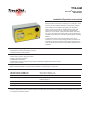
TTA-SIM Single Channel Alarm Module Installation/Operation Instructions
Installing the TTA-SIM
Note: To avoid damage to the TTA-SIM, store the unit in its packaging
until ready to install.
Important: The TTA-SIM is an electronic unit. Take the
following precautions to avoid damage to electronic
components:
Selecting the mounting position
• Handle with care and avoid mechanical shock and impact
• Keep dry
• Avoid exposure to static electricity
• Avoid contact with metal filings, grease, pipe dope and
other contaminants
Choose a location where the module will be protected from the
elements, temperature extremes or heavy vibration. The TTA-SIM is
designed to be wall mounted at any location as long as it does not
create a tripping hazard or expose the TTA-SIM to impact damage.
Mounting the TTA-SIM
• Plan cable/conduit alignment and drill holes as necessary. Cable
entries should all be located in the open space at the right hand of
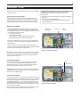
the TTA-SIM (see Figure 2). A typical installation will require holes to
accommodate the following cabling:
- Incoming power supply
- TraceTek sensor leadwire
- [optional] telemetry cable (for RS-485 communication)
- [optional] cable for relay contacts to remote alarm
TTSIM-1A (or
TTSIM-2) unit
Relay unit
Power
terminals
Space
available for
cable entries
• Secure the TTA-SIM enclosure to any convenient vertical surface
using the four corner mounting holes and hardware suitable for the
selected surface.
• Rough-in conduit as required and pull the cables for power and
telemetry. Leave approximately 20 cm (8 in) for connection to TTSIM
terminals. Pull in the sensor circuit leader cable.
Figure 2. Cable entry locations
Note: Rough-in and final connections do not have to be completed at
the same time, however, make sure to replace the cover and tighten
the cover screws if the enclosure will be left in a partially installed
condition overnight or longer.
Power Supply Options
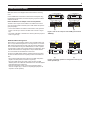
The TTA-SIM has two power supply options available. Depending
on the version being installed and local regulations, the wiring
requirements may vary. In all cases, be sure that each TTA-SIM
receives supply voltage from one and only one source.
Phase
Important: Power supply voltage must be within range specified on
TTA-SIM label (located on inside of enclosure cover; the information is
also located on TTSIM top label).
Connections for Power
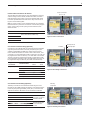
Power and ground (earth) connections to the TTA-SIM are made using
the large cage-clamp power terminal blocks at the right end of the DIN
rail as shown in Figure 3. Cut back the power wires to fit and strip to
expose approximately 6 mm (1/4 in) of conductor. Push the tip of a
small flat-blade screwdriver into the cage clamp actuator to open the
terminal, then insert the wire into the terminal and release the clamp
by removing the screwdriver.
Note: In order to provide maximum electrostatic discharge protection,
and to be CE compliant, the TTA-SIM must be grounded.
Figure 3. Power connections
Neutral
Ground (earth)