1
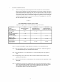
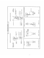
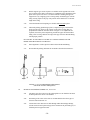
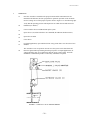
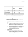
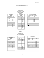
File No. 957:440-15 1 SYSTEM CONSIDERATIONS 1.1 Selection of the proper location and position of the Accutube flow sensor within the piping system is important. The first consideration is to locate the Accutube with proper upstream and downstream straight pipe runs. This is required to assure a fully developed symmetrical flow profile at the Accutube. Accuracy can be affected if sufficient piping is not provided. Table 1 shows recommended straight run requirements with various types of upstream flow disturbances. For inline series sensors the straight pipe run must be of the same schedule/I.D. as the Accutube. TABLE 1 RECOMMENDED STRAIGHT RUNS OF PIPE (Upstream Length in Terms of Internal Diameter of Pipe - See Notes) UPSTREAM FLOW DISTURBANCE ONE ELBOW OR TEE TWO 90 BENDS IN SAME PLANE TWO 90 BENDS DIFF. PLANE REDUCERS OR EXPANDERS ALL VALVES (SEE NOTE 3) WITH STRAIGHTENING VANES 6-8 WITHOUT STRAIGHTENING VANES-IN-PLANE 8 - 10 8 - 10 12 - 15 10 - 12 WITHOUT STRAIGHTENING VANES-OUT-PLANE 24 - 28 8 - 10 8 - 10 8 - 10 10 - 12 24 - 28 24 - 28 Note 1: Downstream straight run of pipe should be a minimum of 4 to 5 internal diameters. Note 2: The values listed in Table 1 are acceptable for most applications. Additional lengths are recommended where precise measurements are desired. Note 3: Recommendations for valve disturbances are for non-throttling (fully open) position only. Note 4: Straightening vanes (where used) shall be installed 2 diameters downstream of the upstream flow disturbance. Note 5: Deviations from the above recommendations will normally not affect repeatability of the flow signal. Note 6: Combination of various types of fittings can cause severe flow distortion, the results of which are unpredictable. Installations with fitting combinations other than those listed above should be approached with caution. Flow straightening vanes are strongly recommended to insure accurate flow measurement. -5-5-