1
File No. 957:440-15
1.2
Determine the position of the Accutube and indicating instrument with respect to the
pipe. Selection of the entry location (i.e. in from top or bottom, etc.) is determined by
considering the fluid in the pipe. Sections 1.2.1 through 1.2.4 give general requirements
for Accutube position and installation, and specific recommendations for each general
category of fluid (1.2.1-Liquid; 1.2.2-Gas; 1.2.3-Steam; 1.2.4-General Requirement).
1.2.1
LIQUID FLOW METERING
1.2.1.1 With liquid flow the readout instrument is normally located below the
Accutube. This prevents air entrapment in the instrument lines.
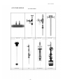
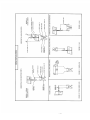
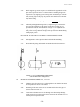
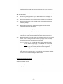
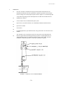
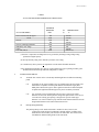
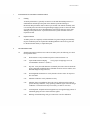
Figures 1.1 through 1.4 show recommended orientation for liquid flow.
1.2.1.2 See Section 1.2.4 General Interconnection Requirements.
1.2.1.3 Instrument lines should be properly sloped (1/2" per foot) without
high points that may cause air entrapment. If this is not possible, air
vent valves must be placed at any high points in piping. Trapped air is a
frequent cause for measurement error with liquids. Refer to Figs. 1.1
thru 1.4.
1.2.1.4 The air vent valves should be bled on a regular basis during normal
operation and upon restart after a system shutdown.
1.2.2
GAS FLOW METERING
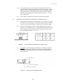
1.2.2.1 Few restrictions apply to system arrangement in dry gas flow. Figures
1.1, 1.2 and 1.5 are recommended for simplicity in installation.
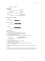
1.2.2.2 For installations where condensation or entrained liquids accumulate in
the instrument piping, it is recommended that the instrument be
mounted above the Accutube or install the Accutube in the top portion
of the line. If mounting the instrument below the Accutube is
necessary, then sediment traps and/or drain valves should be used as in
Figure 1.6.
1.2.2.3 See Section 1.2.4 for General Interconnection Requirements.
1.2.3
STEAM FLOW APPLICATIONS
1.2.3.1 As in liquid flow, the indicator should be located below the Accutube.
Figure 1.1 shows the recommended configuration. This configuration
allows condensate to collect in instrument lines and finds its natural
level within the Accutube. See Figure 1.4 for top entry (probe) in
horizontal lines.
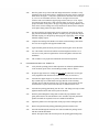
1.2.3.2 An installation in a vertical pipe should only be performed when a
horizontal line location is not available. This installation should be as in
Figure 1.2. A special "rotated head" Accutube is normally used. This
permits side port connection, allowing installation similar to Figure 1.2.
1.2.3.3 See Section 1.2.4 for General Interconnection Requirements.
-6-6-