1
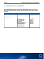
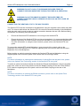
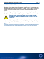
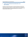
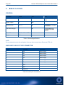
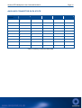
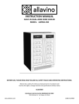
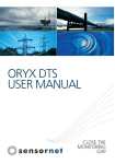
This page intentionally blank.
Sentinal DTS Multiplexer User Guide MUX-UM1.0
Page i
CONTENTS
1.
INTRODUCTION ......................................................................................................................1
2.
AFTER SALES SERVICE ........................................................................................................2
3.
WARRANTY.............................................................................................................................3
Sensornet 12 month Warranty (Support Level 1) .................................................................... 3
Extended Warranty (Support Level 2) ..................................................................................... 3
4.
DECLARATION OF CONFORMITY ........................................................................................4
5.
SAFETY....................................................................................................................................6
General Safety......................................................................................................................... 6
Laser Safety............................................................................................................................. 7
6.
BASIC OPERATION OF THE MULTIPLEXER........................................................................8
The Multiplexer Connections and Controls.............................................................................. 9
7.
OPERATING THE MULTIPLEXER........................................................................................14
8.
USING THE CONFIGURATION WIZARD WITH THE MULTIPLEXER.................................15
The Configuration Wizard Stage 3 – Channel Activation....................................................... 17
Configuration Wizard Stage 7 – Differential Loss Correction ................................................ 18
Configuration Wizard Stage 11 – Trace Averaging ............................................................... 23
Configuration Wizard Stage 13 – Setting the Repetition Time .............................................. 24
Data Files............................................................................................................................... 29
9.
SPECIFICATIONS..................................................................................................................30
General .................................................................................................................................. 30
Auxiliary 9-way D-Type Connector ........................................................................................ 30
Auxiliary Connector Data State.............................................................................................. 31
Page ii
Sentinal DTS Multiplexer User Guide MUX-UM1.0
This page intentionally blank.
Sentinal DTS Multiplexer User Guide MUX-UM1.0
1.
Page 1
INTRODUCTION
The Sentinel DTS system is the most advanced optical fibre distributed temperature sensor
available on the market today. In addition, Sensornet Ltd offers the Sentinel DTS Multiplexer,
allowing the user to connect up to 16 optical fibres from differing installations to the Sentinel DTS
system.
The following user guide has been written to fully explain connection, configuration and use of the
Sentinel DTS Multiplexer. For the remainder of the user guide the Sentinel DTS system will be
referred to as the Sentinel DTS and the Sentinel DTS Multiplexer will be referred to as the
Multiplexer.
Page 2
2.
Sentinal DTS Multiplexer User Guide MUX-UM1.0
AFTER SALES SERVICE
Sensornet Ltd offers a variety of after sales services ranging from fibre health checking and data
monitoring to diagnostics and repair. For more information on these services, contact Sensornet
Ltd on one of the contact details below. When requesting after sales services, please quote the
system serial number complete with hardware model number and software version. These can be
obtained from the Sentinel DTS information window.
NOTE:
It is recommended that the current system information is stored in a safe place in case of a system
failure.
Sensornet Ltd
198 Providence Square
Jacob Street
London
SE1 2DZ
United Kingdom
Tel: +44 (0)20 7394 3555
Fax: +44 (0)20 7394 0555
E-mail: [email protected]
Website: www.sensornet.co.uk
Sentinal DTS Multiplexer User Guide MUX-UM1.0
3.
Page 3
WARRANTY
SENSORNET 12 MONTH WARRANTY (SUPPORT LEVEL 1)
For support level 1, Sensornet offers a return to factory warranty. Sensornet Ltd. will cover costs
associated with repairing the Multiplexer Expansion Unit in the event of a system fault within 12
months of manufacture. This includes the cost of all components and the associated man hours
required to repair the Multiplexer.
Upon receiving the Multiplexer, Sensornet will endeavour to diagnose and repair the fault within a 3
week period. Sensornet will not hold spare components in stock - so in the event that spare
components need to be ordered the customer will have to wait the appropriate lead time (typically
4-8 weeks).
A technical support line is available, whereby the customer can contact Sensornet via e-mail or
telephone and Sensornet will aim for an initial response within 48 hours. This hotline is limited to
technical fault enquiries and does not include data interpretation and management issues.
An annual calibration service is included in this fee. It is assumed that the system calibration will be
carried out remotely (e.g. over a network connection). If for any reason the customer has to ship
the Multiplexer Unit to Sensornet, all delivery costs will be covered by the customer.
NOTES:
1. The above guarantee only covers faults that occur during normal operation. Any faults due to
abnormal operation (e.g. mechanical damage to the system, operating system outside
specifications) are not included in this guarantee.
2. The customer will bear costs for delivering the Multiplexer to Sensornet and Sensornet will cover
delivery costs associated with returning to the customer site.
3. The 3 week return period is not a guarantee but will be based on a 'best effort' approach - this
will be dependent on the severity of the fault.
EXTENDED WARRANTY (SUPPORT LEVEL 2)
A more comprehensive warranty is available which incorporates level 1 and also covers the
following aspects:
Sensornet will carry reserve Multiplexer Units in stock so that in the event of a system fault,
Sensornet will send a replacement to the customer site within 72 hours. The customer will keep
this unit until the faulty system is repaired and returned to the customer.
Please contact Sensornet for additional information.
Page 4
4.
Sentinal DTS Multiplexer User Guide MUX-UM1.0
DECLARATION OF CONFORMITY
The Sentinel DTS and Multiplexer Expansion Unit have been designed with the tightest safety
specifications in mind both from an electrical safety and laser safety viewpoint. The system has
undergone a series of independent third party testing and has been classified with the following
standards.
Laser Safety
EMC
CE Mark
When used with the Sentinel DTS,
the Multiplexer Expansion Unit has
been independently classified to
EN 60825-1 (2001-03) as a Class
1M laser product.
EN61326:1997/A1:1998
Conducted Emissions: Class B
Radiated Emissions: Class A
Accordance with 89/336
EEC EMC Directive
EN 61000-4-3:1996
EN 61000-4-6:1996
EN 61000-4-4:1995
EN 61000-42:1995/A1:1998/A2:2001
EN 61000-4-11:1994
EN 61000-4-5:1995
EN 61000-3-2:1995
EN 61000-3-2:2000
EN 61000-3-3:1995
Accordance with LVD
72/23 EEC Directive:
EN 41003
EN 50178
EN 60065
EN 60825-1
EN 60950
EN 61010-1
Sentinal DTS Multiplexer User Guide MUX-UM1.0
Page 5
Declaration of Conformity
We, the manufacturer,
Sensornet Ltd
198 Providence Square
Jacob Street
London, SE1 2DZ
United Kingdom
declare that the product
Multiplexer Expansion Unit
is in conformity with the following standards in accordance with 89/336 EEC EMC Directive:
EN 61326:1997/A1:1998
EN 61326:1997/A1:1998
EN 61000-4-3:1996
EN 61000-4-6:1996
EN 61000-4-4:1995
EN 61000-4-11:1994
Conducted Emissions Class B
Radiated Emissions Class A
Radiated Susceptibility Class A
Conducted Susceptibility Class A
Electrical Fast Transients Class A
Voltage Dips & Interrupts Class A
EN 61000-4-2:1995/A1:1998/A2:2001 ESD – Enclosure Class A
EN 61000-4-5:1995
Voltage Surges Class A
EN 61000-4-8:1993
Power Frequency Magnetic Field
EN 61000-3-2:1995
Harmonics Class A & D
EN 61000-3-2:2000
Harmonics Class A & D
EN 61000-3-3:1995
Flicker
The manufacturer also declares the conformity of above mentioned product with the actual required safety
standards in accordance with LVD 72/23 EEC Directive:
EN 60825-1:1994/A1:2002/A2:2001
EN 60950-1:2002
Safety of laser products
EN 61010-1:1997
Information technology equipment
C.E.O.:
Safety requirements for electrical
equipment for measurement control
and laboratory use
Technical Director:
Mahmoud Farhadiroushan
Tom Parker
Page 6
5.
Sentinal DTS Multiplexer User Guide MUX-UM1.0
SAFETY
GENERAL SAFETY
The following section provides Warnings, Cautions and Notes covering general safety aspects for
the Multiplexer. Please read all of the safety and operational warnings before connecting and
operating this product.
WARNING! THIS IS A WARNING SYMBOL. THIS SYMBOL IS USED
THROUGHOUT THE USER GUIDE WHENEVER THERE IS A RISK OF
PERSONAL INJURY. ENSURE THAT THESE WARNINGS ARE READ AND
UNDERSTOOD AT ALL TIMES.
CAUTION! This is a Caution symbol. This symbol is used throughout the
user guide whenever there is a risk of damaging the Sentinel DTS system.
Ensure that these warnings are read and understood at all times.
NOTES:
Used throughout the user guide to provide additional information, hints and tips.
WARNING! DO NOT EXPOSE THE DTS SYSTEM TO DAMP, HUMID OR WET
CONDITIONS. FAILURE TO OBSERVE THIS WARNING MAY PRESENT A
RISK OF ELECTRIC SHOCK.
WARNING! THERE ARE NO USER SERVICEABLE PARTS IN THE DTS
SYSTEM. UNDER NO CIRCUMSTANCES SHOULD THE OUTER CASING OF
THE DTS SYSTEM BE REMOVED. FAILURE TO OBSERVE THIS WARNING
MAY PRESENT A RISK OF ELECTRIC SHOCK.
WARNING! DO NOT OPERATE THE MULTIPLEXER IN AN EXPLOSIVE OR
FLAMMABLE ATMOSPHERE. FAILURE TO OBSERVE THIS WARNING MAY
PRESENT A RISK OF EXPLOSION.
CAUTION! The Multiplexer should only be operated by suitably qualified
personnel.
CAUTION! Never operate the Multiplexer if any damage is observed. Contact
Sensornet Ltd for advice.
CAUTION! Do not expose the Multiplexer to adverse temperatures. This may
seriously interfere with the correct operation of the DTS system.
Sentinal DTS Multiplexer User Guide MUX-UM1.0
Page 7
LASER SAFETY
The Multiplexer directs invisible laser radiation which is potentially hazardous if viewed directly by
eye. The laser radiation is directed through the Multiplexer and along the optical fibres using E2000
connectors. An integral feature of the E2000 connector system is a shuttering mechanism that
prevents laser radiation from being emitted when the connectors are disconnected or otherwise not
in use.
The Multiplexer should be interfaced to test fibres using patch cord or pigtail assemblies fitted with
E2000 connectors. The far ends of the test fibres should be terminated to prevent free-space
emission of laser radiation from the fibre end. It is recommended that where possible, E2000
connectors be utilized throughout the optical sensing network.
Due to the potential hazard posed by laser radiation being emitted from exposed fibre ends, the
following safety warnings, cautions and notices should be observed.
WARNING! DO NOT LOOK AT OR EXAMINE EXPOSED FIBRE OR
CONNECTOR ENDS WHENEVER THE DTS IS IN OPERATION.
WARNING! AVOID EYE EXPOSURE TO THE INVISIBLE LASER RADIATION
EMITTED FROM FIBRE CONNECTORS OR EXPOSED FIBRE ENDS.
WARNING! DO NOT EXAMINE OR INSPECT EXPOSED FIBRE OR
CONNECTOR ENDS USING A VIEWING AID SUCH AS AN EYE LOUPE OR
MICROSCOPE.
WARNING! DO NOT UNDERTAKE FUSION SPLICING OR SIMILAR FIBRE
JOINTING WHEN THE DTS IS IN OPERATION.
WARNING! UNDER NO CIRCUMSTANCES SHOULD THE COVER OF THE
MULTIPLEXER BE REMOVED.
Page 8
6.
Sentinal DTS Multiplexer User Guide MUX-UM1.0
BASIC OPERATION OF THE MULTIPLEXER
The Multiplexer will typically be connected to the Sentinel DTS and up to 16 individual 50/125
graded index multimode optical fibres installed in sites of interest as shown in Figure 1. Using the
Sentinel DTS, the Multiplexer can be used to monitor time temperature fluctuations with great
precision.
Figure 1- The Sentinel DTS and Multiplexer in a Typical Installation.
The Multiplexer must be installed, connected and configured before measurements can be taken.
The following section will explain how to connect the Multiplexer to the Sentinel DTS and optical
fibre installations and how to perform a basic system configuration.
Sentinal DTS Multiplexer User Guide MUX-UM1.0
THE MULTIPLEXER CONNECTIONS AND CONTROLS
Figures 2 and 3 show the front and rear views of the Multiplexer.
Figure 2 - The Front View of the Sentinel DTS Multiplexer.
THE CHANNEL INDICATOR LED
This indicates which channel number is currently selected.
THE OPERATING LIGHT
When illuminated this indicates that the Multiplexer is in operation.
Page 9
Page 10
Sentinal DTS Multiplexer User Guide MUX-UM1.0
Figure 3 - The Rear View of the Multiplexer.
THE E2000 OUTPUT COUPLINGS
The E2000 Output Couplings are used to connect 50/125 graded index multimode optical fibre to
the Multiplexer from up to16 installations.
THE E2000 INPUT COUPLING
The E2000 Input Coupling is used to make optical connections between the Sentinel DTS and the
Multiplexer using the supplied patch cord. This may be integral to the Multiplexer.
THE INPUT EXPANSION PORT
The Input Expansion Port is used to connect the Sentinel DTS to the Multiplexer using the supplied
cable.
THE OUTPUT EXPANSION PORT
The Output Expansion Port is reserved for future hardware upgrades by Sensornet Ltd. This port
should not be used.
CONNECTION AND SETUP OF THE SENTINEL DTS MULTIPLEXER
WARNING! BEFORE ATTEMPTING TO CONNECT THE OPTICAL FIBRE TO
THE MULTIPLEXER, ENSURE YOU HAVE READ AND FULLY UNDERSTOOD
THE SAFETY SECTION.
WARNING! UNDER NO CIRCUMSTANCES SHOULD CONNECTIONS BE
MADE, BROKEN OR INSPECTED WHILE THE MULTIPLEXER IS LIVE AND
OPERATING.
Sentinal DTS Multiplexer User Guide MUX-UM1.0
Page 11
WARNING! DO NOT LOOK AT OR EXAMINE EXPOSED FIBRE OR
CONNECTOR ENDS WHENEVER THE MULTIPLEXER IS IN OPERATION.
WARNING! DO NOT EXAMINE OR INSPECT EXPOSED FIBRE OR
CONNECTOR ENDS USING A VIEWING AID SUCH AS AN EYE LOUPE OR
MICROSCOPE.
CONNECTING THE SENTINEL DTS TO THE MULTIPLEXER
The Sentinel DTS must be connected to the Multiplexer using the supplied control cable and patch
cord. The control cable allows the Sentinel DTS to control the channel switching of the Multiplexer
while the patch cord is used to make an optical connection between the two units. Before making
connections, the following must be observed.
•
Ensure the Sensornet DTS software is not running on the Sentinel DTS.
•
Ensure the laser of the Sentinel DTS is not live and operational. It is recommended that while
making connections, the laser interlock should be activated to ensure the laser remains off.
For more information on using the laser interlock, please refer to the Sentinel DTS user
guide.
To connect the sentinel DTS to the Multiplexer, insert one end of the control cable to the
Expansion Port of the Sentinel DTS. Insert the opposing end of the control cable into the Input
Expansion Port of the Multiplexer.
Before making an optical connection between the Sentinel DTS and the Multiplexer using the
supplied patch cord, ensure the patch cord is clean and free of foreign matter.
NOTE:
For further information on cleaning and maintenance of optical fibre and the patch cord, please
refer to the Optical Fibre Technology section of the Sentinel DTS user guide.
To make an optical connection between the Sentinel DTS and the Multiplexer using the supplied
patch cord, insert one end of the patch cord into the E2000 Coupling on the rear of the Sentinel
DTS. Insert the opposing end of the patch cord into the E2000 coupling on the rear of the
Multiplexer.
NOTE:
For further information on inserting the E2000 connectors, please refer to the Optical Fibre
Technology section of the Sentinel DTS user guide.
Page 12
Sentinal DTS Multiplexer User Guide MUX-UM1.0
PREPARING OPTICAL FIBRES FOR CONNECTION
For the correct operation, the end of the optical fibres being inserted into the Multiplexer must be
terminated with a E2000 connector.
WARNING! ONLY A E2000 ANGLED CONNECTOR SHOULD BE USED TO
TERMINATE OPTICAL FIBRES FOR CONNECTION TO THE MULTIPLEXER.
DO NOT ATTEMPT TO USE GENERIC OR BARE FIBRE ADAPTERS.
In addition, the furthest end of the optical fibre should be terminated in such a way as to minimise
end reflections and to prevent inadvertent viewing of the laser light. There are three approved
methods for doing this. They are:
•
To splice a E2000 angled connector onto the end of the optical fibre.
•
To roughly break the end of the optical fibre and cover the end with index matching fluid.
•
To tie a knot of approximately 5mm in diameter at the end of the optical fibre.
In some cases separate lengths of optical fibre may be joined together to build a temperature
sensing fibre network or to make repairs. If this is the case, optical fibres must be joined using one
of the two following methods:
•
A mated pair of E2000 Angled connectors.
•
A Fusion splice using suitable fusion splice hardware.
For further information on optical fibre jointing and termination, please contact Sensornet Ltd.
Sentinal DTS Multiplexer User Guide MUX-UM1.0
Page 13
CONNECTING OPTICAL FIBRES
Depending on the model used, it is possible to connect up to 16 separate channels to the
Multiplexer. In some cases combined or double ended connections may be required. If this is the
case, forward and reverse channels must be paired as follows: channels 1 and 2, 3 and 4 and so
on where the forward channels are the odd numbers and the reverse channels are the even
numbers.
Before connecting the optical fibre to the Multiplexer, ensure that the ends of the optical fibre are
clean and free of foreign matter. For more information on cleaning optical fibres refer to the Optical
Fibre Technology section of the Sentinel DTS user guide.
WARNING! UNDER NO CIRCUMSTANCES SHOULD CONNECTIONS BE
MADE, BROKEN OR INSPECTED WHILE THE MULTIPLEXER IS LIVE AND
OPERATING.
Ensuring the Multiplexer are turned off, remove the masking plug from the desired coupling
bulkhead and insert the E2000 Angled connector into the E2000 Angled coupling on the rear panel
as shown in Figure 9 of the Sentinel DTS user guide.
NOTE:
If the optical fibres are disconnected from the Multiplexer, the masking plugs should be replaced to
prevent contamination of the coupling bulkhead and to prevent any laser light being emitted.
Page 14
7.
Sentinal DTS Multiplexer User Guide MUX-UM1.0
OPERATING THE MULTIPLEXER
WARNING! BEFORE OPERATING THE MULTIPLEXER, ENSURE ALL USERS
READ AND FULLY UNDERSTAND THE SAFETY SECTIONS OF THIS USER
GUIDE.
The Multiplexer will power up when the Sentinel DTS is turned on and its operation is controlled by
the Sensornet DTS software. Once the Sentinel DTS is switched on and the software is started,
the Multiplexer is initialised and the number of channels available are automatically detected.
The currently selected channel is indicated by the Channel indicator LED.
WARNING! THE CHANNEL INDICATOR LED IS FOR INDICATION PURPOSES
ONLY. IT SHOULD NOT BE USED TO GAUGE IF THE OPTICAL FIBRE IS
LIVE OR NOT.
The Multiplexer passes the optical signals from the Sentinel DTS to the particular fibre cable
selected by the software. The channel selected will automatically advance sequentially through
those which are activated by the user. Note that the optical switch does have some loss to the
signal and this will reduce the overall range achievable by the system. The magnitude of the signal
loss depends on the number of channels available in the multiplexer i.e. a two channel multiplexer
will have a lower loss than an 8 channel one.
Sentinal DTS Multiplexer User Guide MUX-UM1.0
8.
Page 15
USING THE CONFIGURATION WIZARD WITH THE
MULTIPLEXER
As explained in the Sentinel DTS user guide, the Configuration Wizard is used to create a new
configuration file whenever the Multiplexer is connected to a new installation. Configuration files
contain important calibration information for an individual installation ensuring the Multiplexer can
accurately measure temperature. The Configuration Wizard is basically of the same format as that
used for a single fibre installation but with a few additional sections. The format of the
Configuration Wizard is shown in Figure 4.
Page 16
Sentinal DTS Multiplexer User Guide MUX-UM1.0
Figure 4 - The Configuration Wizard Format.
Sentinal DTS Multiplexer User Guide MUX-UM1.0
Page 17
The following section describes the additional sections of the Configuration Wizard when using the
Multiplexer. It should be noted that stages 3 to 11 must be completed for each active channel.
Before running the Configuration Wizard with the Multiplexer it is recommended that users are
familiar with the use of the Configuration Wizard for a single fibre installation as described in the
Sentinel DTS user guide.
THE CONFIGURATION WIZARD STAGE 3 – CHANNEL ACTIVATION
The third stage of the Configuration Wizard when using the Multiplexer is to activate selected
channels for distributed temperature sensing. This allows the user to decide which channels are
active whenever this configuration file is used.
The third stage of the Configuration Wizard using the Multiplexer is shown in Figure 5.
Figure 5 - The Third Stage of the Configuration Wizard.
CHANNEL ACTIVATION
To activate the displayed channel for distributed temperature sensing, click the Channel Active
button. The green LED within the Channel Active button will illuminate indicating that the channel
has been activated.
To progress to the next stage of the Configuration Wizard, click the Next button.
Page 18
Sentinal DTS Multiplexer User Guide MUX-UM1.0
If the selected channel is not active when the Next button is clicked, a warning message will
appear as displayed in Figure 6.
Figure 6 - The Channel Inactive Warning Message.
The purpose of the Channel Inactive Warning Message is to inform the operator that the selected
channel is no longer available (active) for distributed temperature sensing measurements. To
return to the Channel Activation stage of the Configuration Wizard and activate the channel, click
the Edit Values button. Alternatively, click the OK button to progress to the next stage of the
Configuration Wizard.
CONFIGURATION WIZARD STAGE 7 – DIFFERENTIAL LOSS CORRECTION
The Seventh stage of the Configuration Wizard when using the Multiplexer is to apply differential
loss correction. This allows the user to remove the effect of any non-uniformities in signal loss.
The seventh stage of the Configuration Wizard using the Multiplexer is shown in Figure 7.
Sentinal DTS Multiplexer User Guide MUX-UM1.0
Page 19
Figure 7 - The Seventh Stage of the Configuration Wizard.
HOW IS DIFFERENTIAL LOSS CORRECTION PERFORMED
In certain circumstances, where the optical fibre is exposed to a hostile environment, for example
areas with high hydrogen levels, the signal loss of the fibre may change over time and vary along
the length of the optical fibre. In the case of hydrogen, this is primarily caused by the ingress of
hydrogen increasing absorption at certain wavelengths. This is most noticeable in single ended or
one way connections. This loss introduces a systematic error into the Sentinel DTS distributed
temperature sensing data. The signal loss can be eliminated by performing a combined
measurement using data from both ends of the optical fibre.
The preferred method of performing a combined measurement is to arrange both ends of the
optical fibre so that they can be connected to two different channels of the Multiplexer. These are
referred to as forward and reverse channels, whereby the forward channel is the beginning of the
optical fibre while the reverse channel is the opposing end. These should be connected as a pair.
NOTE:
It is recommended that forward and reverse channels are paired so that forward channels are odd
numbers and reverse channels are even numbers.
Page 20
Sentinal DTS Multiplexer User Guide MUX-UM1.0
PERFORMING DIFFERENTIAL LOSS CORRECTION
When more than one optical fibre is connected to the Multiplexer, the user must specify if the
channel is to be measured using the single ended or combined method. Set the measurement
method by selecting either Single-Ended or Combined from the Differential Loss Correction digital
control using the up or down buttons. When Combined is selected, the screen will change as
shown in Figure 8.
Figure 8 - The Seventh Stage of the Configuration Wizard using the Combined Measurement
Method.
Selecting a Paired Channel
When using the combined method of measurement, the user must specify the channel number
which is to be paired with the current active channel. The data for the current active channel is
used for the forward data while the data for the paired channel is used for the reverse data. To
select a paired channel, use the up or down buttons to select the correct channel number from the
Paired Channel digital control.
Click the Collect Return Data button to begin data collection for the reverse channel. Once data is
collected the raw stokes and anti-stokes are displayed in the upper graphical display while the
lower graphical display shows the distributed temperature sensing data for both the forward and
combined measurement as shown in Figure 9.
Sentinal DTS Multiplexer User Guide MUX-UM1.0
Page 21
Figure 9 - The Seventh Stage of the Configuration Wizard after Data Collection.
Setting the Optical Fibre Mid Point
The optical fibre mid point is required to specify the overlap of the forward and reverse data
signals. To specify the optical fibre mid point, use the graph palette to zoom in and identify the end
of the raw stokes and anti-stokes trace shown in the upper graphical display. The end point is
where the trace signal drops vertically to zero. The distance along the optical fibre should be noted
and halved. This is the optical fibre mid point.
Alternatively, some suitable feature in the data trace can be lined up between the forward and
reverse traces. The process is made easier if the feature is on or around the centre of the optical
fibre installation.
Once the optical fibre mid point has been calculated, enter the value into the Fibre Mid Point digital
control or use the Fibre Mid Point slider. The graphical displays will be amended to show both the
forward and reverse channels as shown in Figure 10.
Page 22
Sentinal DTS Multiplexer User Guide MUX-UM1.0
Figure 10 - The Seventh Stage of the Configuration Wizard after specifying the Optical Fibre Mid
Point.
As can be seen from Figure 10, the raw stokes and anti-stokes for both the forward and reverse
directions are displayed in the upper graphical display. The forward and reverse traces can be
seen to be symmetrical around the specified mid point. In addition, the distributed temperature
trace can be seen in the lower graphical display. The white trace represents the forward data only
while the red trace represents the combined measurement. Note that it may be necessary for the
user to fine tune the fibre mid-point value by aligning a clear feature on the forward and reverse
raw data display appropriately.
Displaying Channel Data
When performing distributed temperature sensing measurements, it should be noted that only the
forward channel can be used to display temperature. If the reverse channel is selected, then only
the raw data will be displayed.
NOTE:
Data can only be displayed for combined channels after both channels have been measured.
To proceed to the next stage of the Configuration Wizard, click the Next button.
Sentinal DTS Multiplexer User Guide MUX-UM1.0
Page 23
CONFIGURATION WIZARD STAGE 11 – TRACE AVERAGING
The Eleventh stage of the Configuration Wizard when using the Multiplexer is to set the Trace
Averaging. This allows the user to specify the measurement time and the amount of spatial
averaging applied.
The eleventh stage of the Configuration Wizard using the Multiplexer is shown in Figure 11.
Figure 11 - The Eleventh Stage of the Configuration Wizard.
THE EFFECT OF MEASUREMENT TIME ON THE MEASUREMENT CYCLE.
The eleventh stage of the Configuration Wizard allows the user to specify the Measurement Time
and Spatial Averaging for the Sentinel DTS when using the Multiplexer. This stage of the
Configuration Wizard is the same as when running the Configuration Wizard for a single fibre, but
users must be aware of and consider the effects of Measurement time on the minimum repetition
time.
Since it is possible to connect up to 16 different optical fibres to the Multiplexer, the measurement
cycle may consist of up to 16 separate measurement times. This determines the minimum
repetition time. For example, if 16 channels are connected to the Multiplexer, each with a
measurement time set for 1 minute, then the total measurement cycle for all the channels is 16
minutes. Therefore the minimum repetition time must be 16 minutes. In some cases this may be an
unacceptable length of time. To reduce the minimum repetition time, the measurement time for
each channel must be reduced.
Page 24
Sentinal DTS Multiplexer User Guide MUX-UM1.0
CONFIGURATION WIZARD STAGE 13 – SETTING THE REPETITION TIME
The thirteenth stage of the Configuration Wizard is to set the Repetition Time. This allows the user
to set the overall time between consecutive temperature sensing measurements by the Multiplexer.
The thirteenth stage of the Configuration Wizard using the Multiplexer is shown in Figure 12.
Figure 12 - The Thirteenth Stage of the Configuration Wizard.
THE REPETITION TIME WHEN USING THE MULTIPLEXER
As explained in the Sentinel DTS user guide, the repetition time defines the overall time interval
between consecutive temperature sensing measurements by the Sentinel DTS. When using the
Sentinel DTS with the Multiplexer, this time defines the overall time interval between consecutive
temperature sensing measurements for all the optical fibres connected to the Multiplexer.
THE MINIMUM REPETITION TIME WHEN USING THE MULTIPLEXER
The Minimum Repetition time is defined by the aggregate of the individual measurement times of
each of the active channels connected to the Multiplexer. For example, if 8 channels are
connected to the Multiplexer, each with a measurement time of 15 seconds, the minimum
repetition time will be 120 seconds. The minimum repetition time is displayed in the Minimum Rep
Time digital indicator.
Sentinal DTS Multiplexer User Guide MUX-UM1.0
Page 25
SETTING THE REPETITION TIME
To set the repetition time, click in the Repetition Time (s) digital control and enter the required
repetition time. Alternatively, use the up or down buttons to adjust the value. The repetition time
entered must be greater than the minimum repetition time.
Once the repetition time has been entered, the measurement cycle for the Multiplexer is displayed
in the Measurement Times window. This is shown in Figure 13.
Figure 13- The Measurement Times Window.
As can be seen from Figure 9, the measurement cycle is divided into two stages. The coloured
stages represent the individual measurement cycles for each optical fibre, while the black stage
represents the waiting time until the next measurement cycle begins.
SETTING THE NUMBER OF REPETITIONS
Setting the Number of Repetitions for the Sentinel DTS when connected to the Multiplexer works in
the same way as a single fibre installation. For more information on setting the number of
repetitions, please refer to the Sentinel DTS user guide.
Once the repetition time and number of repetitions have been entered, click the Next button to
progress to the next stage of the Configuration Wizard.
If inactive channels are connected to the Multiplexer, the warning message shown in Figure 14 will
appear.
Page 26
Sentinal DTS Multiplexer User Guide MUX-UM1.0
Figure 14 - The Inactive Channels Warning Message.
This Inactive Channels warning message informs the user that inactive channels are present in the
current configuration. Click the Edit Values button to return to the Configuration Wizard and
activate these channels or alternatively click the OK button to progress to the next stage of the
Configuration Wizard.
THE EDIT CONFIGURATION WINDOW
The Edit Configuration window allows the user to review, and if required modify, the calibration
data contained in the configuration file recently created using the Configuration Wizard.
The Edit Configuration window is displayed in Figure 15.
Sentinal DTS Multiplexer User Guide MUX-UM1.0
Page 27
Figure 15 - The Edit Configuration Window.
REVIEWING AND EDITING THE CONFIGURATION FILE
The Installation and Channel Configuration data is displayed in the Edit Configuration window.
Specific channel data can be viewed by selecting the channel using the Channel digital control and
clicking on the appropriately named Tab, for example Range.
Installation and Channel configuration data can be edited in exactly the same way as the
Configuration Wizard by using the digital controls and sliders.
Page 28
Sentinal DTS Multiplexer User Guide MUX-UM1.0
To save any changes made in to the configuration file, click the save button. A new configuration
file will be created with the version number incremented.
NOTE:
The Edit Configuration Window can be accessed through the Sentinel DTS Main Menu by
selecting Edit Configuration and then selecting Go Straight to Editor from the pull down menu.
EXITING THE EDIT CONFIGURATION WINDOW
To exit the Edit Configuration window and start performing distributed temperature measurements
using the Sentinel DTS system, click the OK button.
NOTE:
Clicking the OK button will cause the configuration data to be saved to file and the configuration file
version number will be updated. For more information on the configuration file name structure,
please refer to the Data File Structure section in the Sentinel DTS user guide.
To exit the Edit Configuration window without saving any changes, click the Cancel button. The
message shown in Figure 16 will be displayed.
Figure 16 - The Exit Configuration Editor Confirmation Message.
Click the OK button to exit to the Choose Configuration Setup menu. New or existing configuration
files can be created or edited from this menu as described in previous sections.
Sentinal DTS Multiplexer User Guide MUX-UM1.0
Page 29
DATA FILES
The temperature data is saved into the two file types *.dtd and *.ddf as described in the Sentinel
DTS User Manual. There are however some slight differences when the Multiplexer is attached.
•
One directory will be created for each active channel under the <Installation name> directory.
These are by default labelled ‘Channel 1’, ‘Channel 2’ and so on. However the user may alter
these names to something more meaningful if required (by using the configuration wizard or
editor).
•
If performing a combined measurement, the *.ddf files in the directory for the forward channel
will contain both the forward and reverse stokes and anti-stokes data. The only data file
written for the reverse channel is the *.tcd file, which contains the external PT100 probe
readings.
•
If the acquisition for a combined measurement is terminated prematurely, the data status
field in the header may show “Invalid”.
Page 30
9.
Sentinal DTS Multiplexer User Guide MUX-UM1.0
SPECIFICATIONS
GENERAL
Parameter
Value
Unit
Note
Power
+12/+5
V
Supplied from Sentinel
DTS
Optical Output
1
Mw
-
Insertion Loss
0.5 - 2
dB
Dependent on number
of channels
Laser Wavelength
-
nm
As specified in the
Sentinel DTS User
Manual
Overall Dimensions
483W x 88H x 473D
mm
-
Weight
5.7
kg
-
Table 1 General Specifications
NOTE:
Do not attempt to power the multiplexer from any other source than a Sensornet DTS unit.
AUXILIARY 9-WAY D-TYPE CONNECTOR
Pin No
Function
Comment
1
D0
Active High
2
D1
Active High
3
D2
Active High
4
D3
Active High
5
D4
Active High
6
Busy
Active High
7
N/A
8
N/A
9
Common
Table 2 Auxiliary Pin Connections
Sentinal DTS Multiplexer User Guide MUX-UM1.0
Page 31
AUXILIARY CONNECTOR DATA STATE
Active Fibre
Channel
D0
D1
D2
D3
D4
1
0
0
0
0
0
2
1
0
0
0
0
3
0
1
0
0
0
4
1
1
0
0
0
5
0
0
1
0
0
6
1
0
1
0
0
7
0
1
1
0
0
8
1
1
1
0
0
1
1
1
1
0
…
16
Table 3 Auxiliary Connector Data State
Page 32
Sentinal DTS Multiplexer User Guide MUX-UM1.0
This page intentionally blank.
This page intentionally blank.
Sensornet Ltd
198 Providence Square
Jacob Street
London
SE1 2DZ
United Kingdom
Tel: +44 (0)20 7394 3555
Fax: +44 (0)20 7394 0555
E-mail: [email protected]
Website: www.sensornet.co.uk