1
NSC10 NETWORK CAMERA
USER MANUAL
MODEL 503792
INT-503792-UM-0608-04
Contents
1.
Introduction............................................................................................................ 1
2.
3.
4.
Package Content................................................................................................... 1
System Requirement............................................................................................. 1
Hardware Installation............................................................................................. 2
5.
6.
4.1.
LED and Focusing ............................................................................................2
4.2.
Camera Ports....................................................................................................3
4.3.
Installation Procedure .......................................................................................4
Software Installation .............................................................................................. 5
Using the Administrator Utility ............................................................................. 10
6.1.
General Setting............................................................................................... 11
6.1.1.
7.
8.
Configure Camera...................................................................................12
Installing the IP Camera Surveillance Software.................................................. 15
7.1.
Using the IP camera surveillance software.....................................................17
7.2.
Configure the IP Surveillance Software ..........................................................20
7.3.
General Settings .............................................................................................28
7.4.
Change Display Layout...................................................................................33
7.5.
Scan function ..................................................................................................36
7.6.
ZOOM and PTZ Controls................................................................................37
7.7.
Snapshot.........................................................................................................38
7.8.
Recording .......................................................................................................38
7.9.
Playback .........................................................................................................39
Web Connection and Setup ................................................................................ 40
8.1.
Camera Setting...............................................................................................42
8.2.
LAN Setting.....................................................................................................44
8.3.
E-Mail and FTP...............................................................................................47
8.4.
Motion Detection.............................................................................................49
8.5.
System............................................................................................................50
8.6.
Status..............................................................................................................51
8.7.
Users ..............................................................................................................52
8.8.
Log..................................................................................................................53
9. Frequently Asked Questions ............................................................................... 54
10. Technical Specifications...................................................................................... 55
11. Appendix A Router/Gateway Setup for Internet Viewing .................................... 56
12. Appendix B Set up WLAN step by step .............................................................. 57
13. Appendix C Viewing via UPnP in Windows XP................................................... 63
14. Appendix D Configure Windows 2003 Server..................................................... 66
1. Introduction
Thank you for choosing the INTELLINET NETWORK SOLUTIONS NSC10 Network Camera.
This NSC10 Network Camera sends live video through 10/100 Mbps wired network to a web
browser or camera viewer across Internet anywhere in the world! This compact,
self-contained unit lets you keep an eye on your home, your kids, and your
workplace—whatever’s important to you.
How does the Camera do all of this? Unlike standard “Web cams” that require an attached PC,
the NSC10 Network Camera can connect directly to a network. The MJPEG video
compression produces a high quality, high frame-rate, 640 x 480 video stream.
The included 16-channel Camera Viewer utility lets you record the video to your local hard
drive, “live” or on a predetermined schedule. Use the instructions in this Guide to help you
integrate the Camera into your network. These instructions should be all you need to get the
most out of the NSC10 Network Camera.
2. Package Content
One NSC10 Network Camera
One Power Adapter
One Camera Stand
One Category 5 Ethernet Cable, 1 m
One Quick Installation Guide
One CD (Including Manual/Utility/Driver)
If any of the above items are missing, please contact your supplier.
3. System Requirement
System requirement for PC, MAC or Notebook PC to access the NSC10 Network Camera are:
OS System: 2000, XP + SP2, Server 2003, Vista, Windows 7
IE Version: 6.0.29 + SP2 or above
CPU: Intel Pentium III 750MHz above or Intel Celeron 1GHz above
Memory Size: 128MB (256MB recommended)
DirectX 9.0 or above
VGA card with fully DirectX 9.0 supported.
VGA Card Resolution: 800 x 600 or above
1
4. Hardware Installation
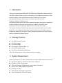
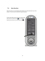
4.1.
LED and Focusing
The Camera head and its focus ring allow you to modify the aim and focus of the Camera.
To adjust the Camera’s focus, rotate the dark focus ring.
There are four LEDs indicating the camera status and networking status.
y
Power
When the camera is power on, the LED will light.
y
LAN
When the NSC10 Network Camera is linking to wired network, the LED is lighting. The
LED is flashing when video is transmitted or received through wired network.
Wireless SMA Connector
(Wireless Model Only)
LED Green:
LAN Activity
Focus Ring
This LED has
no function.
LED Blue:
Power On
2
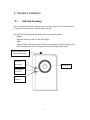
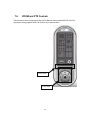
4.2.
Camera Ports
The Camera features three ports and a Reset button.
y
Power
The Power port is where you can connect the power adapter.
y
LAN
The LAN port is where you can connect the Ethernet network cable.
y
WLAN (Antenna Connector)
This round connection is standard Reverse SMA connector where any antennas with
Reverse SMA connector can connect to the SOHO Network Camera..
y
Reset
1.
If problems occur with your NSC10 Network Camera, press the reset button
with a pencil tip (for less than 2 seconds) and the NSC10 Network Camera
will re-boot itself, keeping your original configurations.
2.
If problems persist or you experience extreme problems or you forgot your
password, press the reset button for longer than 5 seconds and the NSC10
Network Camera will reset itself to the factory default settings (warning:
your original configurations will be replaced with the factory default
settings).
Power Jack
LAN Port
3
Reset Button
4.3.
Installation Procedure
1. Unpack the NSC10 Network Camera package and verify that all the items listed in Chapter
2 are provided.
2. Connect the NSC10 Network Camera to your network by attaching the network cable from
the switch/router to the UTP port of the NSC10 Network Camera.
3. Connect the power adapter to the NSC10 Network Camera and plug the power adapter in
the power outlet. When the NSC10 Network Camera is ready, the Ready LED will light.
4. Make sure that you have installed the correct VGA driver and DirectX 9.0 or above.
Note: It is highly recommended that you use the power adapter shipped with the NSC10
Network Camera, do NOT use any other power adapter from any other sources.
4
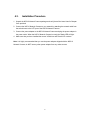
5. Software Installation
Follow the simple steps below to run the Install Wizard to guide you quickly through the
Installation process. The following installation is implemented in Windows XP. The installation
procedures in Windows 2000/Server 2003 and Vista are similar.
1. Insert the CD shipped along with the NSC10 Network Camera into your CD-ROM drive.
The “Autorun.exe” program should be executed automatically. If not, run “Autorun.exe”
manually from “Autorun” folder in the CD.
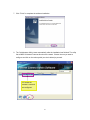
2. The Install Wizard will show four selections. Select the program you want to install or click
“Exit” to install the program later. Select “Install Administrator Utility”.
5
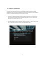
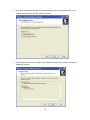
3. The system will start the installation procedures. Click “Next” to continue installation.
4. If you wish to install the software program in an alternate location, click “Change”;
otherwise click “Next” to move on to the next step.
6
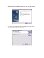
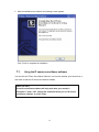
5. Click “Install” to start installing the program.
6. The system will install the program automatically.
7
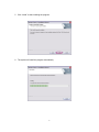
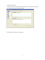
7. Click “Finish” to complete the software installation.
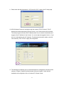
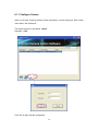
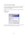
8. The ”Administrator Utility“ starts automatically after the installation has finished. The utility
lists all NSC10 Network Cameras found on the network. Choose the one you want to
configure and click on the tools symbol (see circle below) to proceed.
“N” means the
camera is new and
not configured.
8
9. Please enter the default password “1234” and click “OK” to login to the IP setup page.
10. NSC10 Network Camera is working through the network (TCP/IP Protocol). The IP
address and subnet mask setting must be correct, or you cannot access to the camera.
The wizard program will detect the IP address status of your network automatically and
suggest a free IP address for the Camera. You can accept the suggested value or, if you
have an understanding about IP networks, IP addresses and network masks, enter the
value manually. Click “Finish” to apply the configuration.
11. The following two chapters go into more details about the configuration and setup of the
cameras. Chapter 6 explains the Administrator Utility and chapter 7 deals with the
installation and configuration of the 16-channel IP Camera Viewer.
9
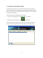
6. Using the Administrator Utility
The Administrator Utility allows users to search and setup the cameras located within the
Intranet or on the Internet. From the utility, users can view all the information of the selected
camera; furthermore, it provides a setting wizard, which can guide users to add the camera to
the network easily and promptly.
There are two ways to run the Administrator Utility as follows.
1. Click “Start”, select “Programs\IP Camera\Admin Utility” to run the utility.
to run the utility.
2. Double click the “IP Camera Admin” icon
Once the utility is started, it searches for all the cameras in the network and displays them.
You can then perform configuration tasks which are explained on the following pages.
10
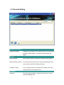
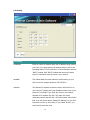
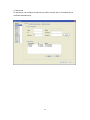
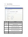
6.1. General Setting
Information of Camera
Camera Information
It displays all information of the selected camera. The information
includes the MAC address, IP Address, Camera Name and
Model.
Task Bar
Search Camera
Click ‘’Search Camera’’ to search for cameras on the network.
Browse Camera via Web
Click ‘’Browse Camera via Web’’ to open the Web browser and
auto-connect to the NSC10 Network Camera/
Configure Camera
Click ‘’configure camera’’ to change the IP settings, user name
and password of the selected camera.
Languages
Language
This utility supports English, Japanese and Chinese. You can
select the language here.
11
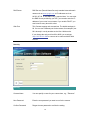
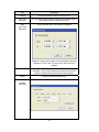
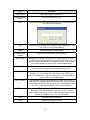
6.1.1. Configure Camera
When you click the “Configure Camera” button (see below), a screen will pop-up. Enter a valid
“User Name” and “Password”.
The default values are: User Name: “admin”
Password: “1234”
Click "OK" to begin with the configuration.
12
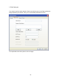
LAN Setting
LAN Setting
IP Address
Enter an unused IP address within the IP address range used on
your LAN. If you don't know the IP address range, or don't have
knowledge about TCP/IP networks, it is recommended to activate
"DHCP" instead. With "DHCP" enabled the camera will obtain
proper IP information from the router in your network.
NetMask
The Subnet Mask field must match the subnet setting on your
LAN. A common example would be 255.255.255.0.
Gateway
The Gateway IP address must be the same, which the PCs on
your LAN use. Typically this is the IP address of the router in your
network. For example, if you know the router in your network
operates on IP address 192.168.1.254, then you can be
reasonably certain, that 192.168.1.254 is the correct value for this
field. If you don't know what a Gateway IP address is, or you don’t
know how to look it up, don't worry. If you enable "DHCP", you
won't need to enter this value.
13
DNS Server
DNS Servers (Domain Name Servers) translate Internet domain
names such as www.google.com to IP addresses such as
64.233.187.99. A valid DNS entry is required here. You can enter
the DNS Server provided by your ISP, you can also enter the IP
address of your router in most cases. If you enable "DHCP" you
won't need to worry about this value.
Web Port
This Camera supports web connections. The default web port is
80. You can use a different port for the camera, for example if port
80 is already in use by another service like a Web service.
If you change the web port from 80 to 8080, you must type
http://192.168.2.3:8080 to connect to he camera with the Web
browser.
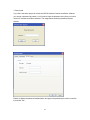
Security
Security
Camera Name
You can specify a name for your camera here, e.g., "Entrance".
New Password
Enter the new password you want to use for the camera.
Confirm Password
Retype the new password to confirm the setting.
14
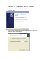
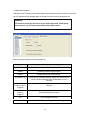
7. Installing the IP Camera Surveillance Software
1. Double-click the setup file located on the supplied CD-ROM. When the following window
appears, click "Next."
2. You can specify the destination folder of the software installation or you can just use the
default folder, and click "Next" to continue.
15
3. If you want the installation program to create a desktop icon or a quick launch icon for you,
select the desired items and click "Next" to continue.
4. The next screen presents a summary of the installation options. Click "Install" to begin the
installation process.
16
5. After the installation has finished, the following screen appears:
Click "Finish" to complete the installation.
7.1.
Using the IP camera surveillance software
You can click the "IPCam Surveillance Software" icon from the desktop, quick launch bar, or
start menu to start the IP camera surveillance software.
Before you start:
IP camera surveillance software will only work when your monitor’s
resolution is "1024 x 768". Change the resolution before you use IP camera
surveillance software, or it won’t start.
17
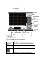
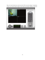
Here are descriptions for all components of the IP camera surveillance software:
Video display area
Language
Display
layout
Full screen /
Scan
Zoom Out /
Zoom In
PTZ Control /
Home
Message display
Recording / System
box
configuration
Playback / Snap shot
EXIT Program
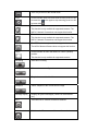
Below is a description of the buttons and their functions.
Item
Description
Video display
The image of all connected cameras will be displayed here.
area
Language
Select a language from this dropdown menu to change the
display language.
Display layout
There are eight kinds of available display layouts. Click a
layout icon to change camera display layout.
Full screen
Click this button to switch to full screen mode and press
18
"ESC" key to return to the normal mode.
Scan
Click this button once to activate scan function (scan icon will
become blue
become white
Zoom out
); click again to stop scanning (scan icon will
).
Zoom-out
This function is only available for supported cameras. The
NSC10 Network Camera does not support this function.
Zoom In
Zoom-in
This function is only available for supported cameras. The
NSC10 Network Camera does not support this function.
PTZ control
The PTZ function is only available for supported cameras.
The NSC10 Network Camera does not support this function.
Home
Click this button to return the camera to "Home" (default)
position.
This function is only available for supported cameras.
Recording
Start video recording.
Configure
Software / camera configuration.
Playback
Play back a recorded video file.
Snapshot
Take a snapshot of the current camera image.
Message display
Displays all system messages ("camera is disconnected".
etc.).
EXIT
Terminates the IP camera surveillance software.
Minimize window
Minimizes the IP camera surveillance software window.
19
Video display
Displays the image of all cameras by the display layout you
area
have selected.
7.2.
Configure the IP Surveillance Software
1. Configure cameras
Before you use this IP camera surveillance software, you must configure the camera(s) you
wish to connect. Click the "System configure" button
and a popup menu will appear:
Select ‘Configure Cameras’:
Note: If you’re prompted by a windows security alert which asks you if you
want to block "IPCamViewer" program, click "Unblock". Failure to do so may
result in the IP camera surveillance software not functioning correctly.
20
2. Camera tab
On this tab you can configure all cameras you wish to connect. Up to 16 cameras can be
connected simultaneously:
21
Here are the descriptions of all setting items:
Item
Channel
Description
Select the channel number you wish to set.
Camera Search
All cameras found on your local network will be displayed in
the "Camera Search" box.
Select
Select a camera listed in the "Camera Search" box, and click
‘Select’ to fill all parameters of the selected camera in every
camera configuration fields.
Refresh
Rescan all cameras on your local network. This function
updates the list and always shows the current cameras found
on your network.
Name*
Input the name of the camera here. Default value is the first 6
bytes of the camera’s MAC address. You can change the
name of the camera so you can remember the camera’s
location or purpose easily.
Model
Displays the model of the selected camera. This field can not
be changed.
IP*
Input the IP address of the camera.
Username*
Input the user name of the camera.
Web Port*
Input the Web port of the camera. By default it’s "80".
Password
Input the password of the camera. Default value is ‘1234’.
Video Format**
Reset
OK
Cancel
Select the video encoding format of this camera: Select
"MJPEG", not "MPEG4".
Clear all fields in ‘Camera Configuration’ section.
Save settings in this tab.
Discard all settings in this tab.
* It’s recommended to use the "Select" button to fill the content of this field.
** Only available for cameras that support this function.
22
After you’ve set all channels you wish to set, click "OK" to save the settings. If everything’s
correct, you’ll see the camera’s image in the IP camera surveillance software’s main menu:
23
3. Schedule Recording tab
On this tab, you can set up a scheduled video recording, so you can record the video captured
by all cameras you have by a pre-defined schedule.
Find a description of all options on the next page:
24
Item
Description
Channel
Select the channel number you wish to set.
One Time
Schedule
You can specify the one-time schedule for a selected camera;
this schedule will be executed once only.
New
Click this button and a new window will appear:
(One Time
Schedule)
Specify the time duration of this one-time schedule (the date
and time of "From" and "To"), then click "OK" to save the
settings.
Edit
You can modify a scheduled recording item. Select a
schedule in "One Time Schedules" list, and click the "Edit"
button to edit the start and end time of this schedule.
Delete
Delete a selected schedule item.
New
Click this button and a new window will appear:
(Weekly
Schedule)
25
You can define a recording schedule that will be executed at
the specified time of certain weekday(s) in a week. Check all
weekdays that apply, and set the start time in the "From" field.
You can set the duration of the video recording in the "Period"
field (format is HH:MM:SS), and the end time will be
calculated automatically and displayed in the "To" field. You
can also click "All Time Record" to define a recording
schedule that will be executed every weekday, from
12:00:00AM to 11:59:59PM.
Click "OK" to save changes.
Edit
You can modify a scheduled recording item. Select a
schedule in the "One Time Schedules" list, and click "Edit"
button to edit the start and end time of this schedule.
Delete
Delete a selected schedule item.
OK
Save settings on this tab.
Cancel
Discard all settings on this tab.
4. Audio tab
This menu has no function, as the 503792 SOHO Network Camera does not support audio.
26
5. Motion Recording tab
With this function activated, only motion captured by the camera will be recorded, so you don’t
have to waste hard disk storage space on images you don’t need to pay attention to.
WARNING:
This function should not be used to secure high-value items. Good-quality
alarm sensors, e.g., IR based, will provide more reliable results.
Below are the descriptions of the setup options:
Item
Description
Channel
Select the channel number you wish to set.
Enable
Enable the motion record function.
Disable
Disable the motion record function.
Recording Time
Select the time duration that the camera will record when a
motion has been detected from the dropdown menu in
seconds.
Invoke alarm
when motion is
triggered
Send an alarm when a motion has been detected by the
camera.
Send mail when
motion is
triggered
Send an email to a pre-defined address when a motion has
been detected by the camera.
OK
Save settings on this tab.
Cancel
Discard all settings on this tab.
27
7.3.
General Settings
This menu gives you access to important settings of the 16-channel viewer.
1. General tab
Item
Description
Data Directory
Set the directory (folder) you wish to store the recorded video
and captured image. Click "Browse" to select a directory.
Free Recording
Space
Displays the remaining storage space on the drive where the
data directory is located.
Max Video File
Size
Defines the maximum file size of a video file. The example
shows 50 MB, which means that the camera viewer will
create AVI videos in chunks of 50 MB.
Scan Time
Define the time period to pause between every camera
switch when you activate "Scan" function.
Cycle Recording
You can decide the behavior when hard disk space is full:
Disable: Do not overwrite recorded video files.
Enable: Overwrite recorded video files.
OK
Save settings on this tab.
Cancel
Discard all settings on this tab.
28
2. E-Mail Setting tab
If you want to use the motion detection function and wish to get an e-mail that contains the
image captured by the camera, set up your e-mail-related parameters here first.
Find explanations about the options on the next page.
29
Item
Description
E-Mail Subject
Specify the subject of the e-mail.
Recipient E-Mail
Address
All e-mail addresses you set.
New
Click this button and you’ll be prompted to input the e-mail address.
Click "OK" to save changes.
Edit
Select an e-mail address from "Recipient E-Mail Address" box, and
click "Edit" to edit the email address.
Delete
Delete the selected e-mail address.
Sender E-Mail
Address
Specify the e-mail address of e-mail sender.
SMTP Server
Specify the IP address or host name of the SMTP server you wish to
use. ISPs will only allow subscribers to use their SMTP server. If you
don’t know which SMTP server you should use, refer to the setting of
your e-mail software or ask your ISP / network administrator.
SMTP port
Specify the port number of the SMTP server you wish to use. By
default (and the setting of most of SMTP servers) it’s ‘25’.
SMTP Auth
Select "Enable" if your SMTP server requires authentication, select
"Disable" if it’s not required. If you don’t know if your SMTP server
requires authentication, refer to the setting of your e-mail software or
ask your ISP / network administrator.
SMTP Account
Input the SMTP account (username) of your SMTP server here. In
most cases, it’s the same as your POP3 username (the one you use
to receive email). Refer to the setting of your e-mail software or ask
your ISP / network administrator if you’re not sure about this.
SMTP Password
Input the SMTP password of your SMTP server. In most cases, it’s
the same as your POP3 password (the one you use to receive
email). Refer to the setting of your e-mail software or ask your ISP /
network administrator if you’re not sure about this.
OK
Save the settings on this tab.
Cancel
Discard all settings on this tab.
30
3. Security tab
If you don’t want other people to access the NSC10 Network Camera surveillance software,
you can set a password to protect it. You’ll need to input the password every time you wish to
use this IP camera surveillance software. The image below shows the password request
window.
Enable or disable the password authentication and type in the password (re-enter it to confirm
it) and click "OK."
31
4. About tab
The software version is shown here. Be sure to write down the number and have it handy
before contacting the technical support team.
32
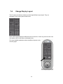
7.4.
Change Display Layout
This IP camera surveillance software provides eight different layout styles. They are
selectable via the control panel shown below:
Each of the designs displays a different amount of cameras. In order to get a full-screen view
of a camera, click on the button as indicated below.
Find more detailed explanations about the different layouts on the
next two pages.
33
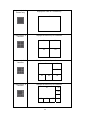
Layout style 1: 1
Camera only
Displays the video of 1 camera only.
01
Layout style 2: 4
Cameras
Layout style 3: 6
Cameras
Displays the video of up to 4 cameras.
01
02
03
04
Displays the video of up to 6 cameras.
02
01
03
04
Layout style 4: 8
Cameras
05
06
Displays the video of up to 8 cameras.
01
02
03
04
05
06
34
07
08
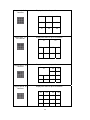
Layout style 5: 9
Cameras
Layout style 6:
10 Cameras
Layout style 7: 13
Cameras
Layout style 8: 16
Cameras
Displays the video of up to 16 cameras.
01
02
03
04
05
06
07
08
09
Displays the video of up to 10 cameras.
01
02
03
04
05
06
07
08
09
10
Displays the video of up to 13 cameras.
01
02
03
04
05
06
07
08
09
10
11
12
13
Displays the video of up to 16 cameras.
01
02
03
04
05
06
07
08
09
10
11
12
13
14
15
16
35
7.5.
Scan function
With this function you can periodically switch between the cameras that are set up in the
software. The scan interval is defined in the general options.
Click the scan button once to activate the scan function
(the scan icon will become blue
); click it again to
stop the scan (the scan icon will become white
36
).
7.6.
ZOOM and PTZ Controls
These functions are not supported by the NSC10 Network Camera Model 503792. Don't be
surprised if nothing happens when you click on any of these buttons.
Zoom in/out
PTZ Control
37
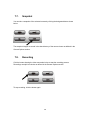
7.7.
Snapshot
You can take a snapshot of the selected camera by clicking the designated button shown
below.
The snapshot images are saved in the data directory of the camera viewer as defined in the
General Options section.
7.8.
Recording
Click the button showing the video camcorder below to start the recording process.
Recordings are split into chunks as defined in the General Options section.
To stop recording, click the button again.
38
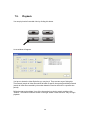
7.9.
Playback
You can play back all recorded video by clicking this button.
A new window will appear:
You have to locate the video file before you can play it. There are two ways of doing this:
Time Search (search all video files which fall within a specific time period) and Motion Search
(search all video files recorded by the motion detection function which fall in a specific time
period).
Define the start and end date / time of the time period you wish to search, and then click
"Search". The search results are shown on the right. Select a video and click "Play" to begin
playback.
39
8. Web Connection and Setup
You can use the Web browser to connect the camera for viewing or setting. Open the web
browser and enter the IP Address of the camera to establish a connection. The default IP
Address of the camera is “192.168.2.3”.
When the welcome screen appears, enter the “Admin Name” and “Password”. The default
values are:
Admin Name: “admin”
Password: “1234”
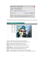
When the camera is connected, the browser will take you to the live video page. If you are viewing this
camera at first time, the following dialog will appear to install the ActiveX plug in.
40
After installed the ActiveX plug-in, the video image will be shown up in the web screen directly.
The menu options for the web control screen are as follows.
Camera – View live video and adjust the video format from the menu.
LAN – Setup the camera LAN port functions in the menu.
WLAN – Setup the camera WLAN port functions in the menu.
E-Mail & FTP – Setup the E-Mail client and FTP client in the menu.
Motion Detection – Configure the Motion Detection Actions here.
System – Setup System utilities and settings in this menu.
Status – Shows the camera information and current status in this page.
Users – This camera support up to 4 user accounts. You can setup them in this menu.
41
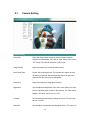
8.1.
Camera Setting
Camera Setting
Resolution
Select the desired video resolution format. Larger resolution
requires more bandwidth. 640 x 480 is “VGA” format. 320 x 240 is
“CIF” format. The default resolution is CIF format.
Image Quality
Adjust this property to control the video quality
Max Frame Rate
Set the video max frame rate. This camera can support at most
30 frames per second. Set the frame rate higher can get video
more smooth. But will use more bandwidth.
Frequency
Adjust this property to fitting light frequency.
Brightness
You can adjust the brightness of the video. If the video is too dark,
you can input the larger number in this text box. The video will be
brighter. This value can be from 1 to 100.
Contrast
You can adjust the contrast by change the value. This value can
be from 1 to 100.
Saturation
You can adjust the saturation by change the value. This value can
42
be from 1 to 100.
Hue
You can adjust the hue by change the value. This value can be
from 1 to 100.
Whiteness
You can adjust the white balance by change this value.
This
value can be from 10 to 30.
Enable Auto Exposure
You can enable Auto Exposure by check this box.
Enable OSD
You can enable or disable “Time Stamp” function in this item.
When you disable “OSD” function, the “Time Stamp” will be
hidden.
Apply
When you finish “AV Server” setting, click this button to validate
the setting values.
43
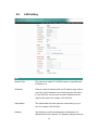
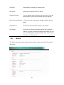
8.2.
LAN Setting
LAN
Network Type
This camera can obtain IP via DHCP protocol or specified static
IP Address to it..
IP Address
Enter an unused IP Address within the IP address range used on
your LAN. If the IP Address of your LAN is from the 192.168.2.0
to 192.168.2.250, you can set an unused IP Address from the
range for the camera, for example: 192.168.2.250.
Subnet Mask
The Subnet Mask field must match the subnet setting on your
LAN. For example: 255.255.255.0.
Gateway
The Gateway is used to forward frames to destinations in a
different subnet on the Internet. The Gateway setting must be the
44
same with the gateway used by the PCs on your LAN.
DNS Server
DNS Server (Domain Name Server) that translates names to IP
addresses. Set the same DNS Server as the PCs on your LAN.
Video Port
The AV Control Port is used to transmit or receive the AV
streaming in the network. The default port setting is “4321”. If you
want to view the video from the camera, the port setting should
be correct.
Web Port
This camera support web connection, the default web port is 80.
Since the web server may use port 80, you can use a different
port for the camera. If you change the web port from 80 to 8080,
you must type http://192.168.2.3:8080 to connect the camera
through the web browser.
Apply
When you finish the “LAN”, click “Apply”.
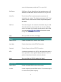
PPPoE
Enable PPPoE
Enable or disable PPPoE function of the camera.
User Name
Enter the User Name for the PPPoE Connection.
Password
Enter the Password for the PPPoE Connection.
MTU
A maximum transmission unit (MTU) is the largest size packet or
frame, specified in octets (eight-bit bytes), that can be sent in a
packet or frame based network such as the Internet.
Apply
When you finish the “PPPoE” setting, click “Apply”.
Dynamic DNS
Enable DDNS
Enable or disable DDNS function of the camera.
Provider
Several companies provide DDNS service. This camera supports
the service from DynDNS company.
45
Domain Name
The domain name given by DynDNS is
“registername.dyndns.com”. Enter the domain name that you
register for the camera from DynDNS web site.
User Name
Enter the login name for the DDNS service.
Password
Enter the password for the DDNS service.
Apply
When you finish the “Dynamic DNS” setting, click “Apply”.
UPnP
Enable UPNP
Enable or disable UPnP function of the camera.
Apply
When you finish the “UPnP” setting, click “Apply”.
LoginFree
Filename
The default value is “loginfree”. That’s mean user can get a snapshot
image from Internet Explorer. The format is like:
IP Camera will send a snapshot image to Internet Explorer.
If user changed file name (Ex: “1234”), the URL must be changed to
“http://192.168.2.3/1234.jpg”
Apply
When you finish the “UPnP” setting, click “Apply”.
46
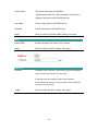
8.3.
E-Mail and FTP
The “E-Mail & FTP” lets you setup E-Mail client and FTP client that camera can sent live video
to your e-mail account or FTP server when Motion has been detected.
AV Server
Recipient E-Mail Address
This camera supports “Motion Detection” function. Enter the
E-Mail Account for receiving the pictures.
SMTP Server
Enter the SMTP Server for the E-Mail sending.
Sender E-Mail Address
Specified the e-mail address of the e-mail sender.
SMTP Authentication
Enable or Disable the SMTP Authentication function
Username
When Authentication is enabled, input the SMTP Username.
47
Password
When Authentication is enabled, input the password.
Send a Test Email
Press this button to send a test e-mail to your mailbox. You can
use this function to test if your setting is correct.
FTP Server
This camera supports “Motion Detection” functions. When Motion
Detection event occurred, you can record the pictures to FTP
server. Enter the FTP address for receiving the pictures.
FTP Port
Enter the port of the FTP server.
User Name
Specify the user account of ftp server.
Password
Specify the Password of your ftp account.
Remote Folder
Specify the folder of the ftp site that you want to store the video.
Password
When Authentication is enabled, input the password.
Passive Mode
If your Camera is under NAT, you usually need to enable this
feature.
48
8.4.
Motion Detection
The “Motion Detection” allows users to setup the behavior of motion detection feature.
Motion Detection
Motion Detection Enable
Enable or Disable the Motion Detection Function.
Next Event Detected
Setup the interval between two events. For example, if you setup
Interval
the interval to 5 seconds, the next event will start after this event
finished + 5 seconds.
Threshold
Setup the sensitivity of motion detection.
Send Recording File to
Select Yes to send the recorded video file to your e-mail account
E-Mail
that you had specified at “E-Mail & FTP” menu.
E-Mail Subject
Specify the subject of motion detection notify e-mail.
Send Recording File to
Select Yes to send the recorded video file to your FTP server that
FTP
you had specified at “E-Mail & FTP” menu.
49
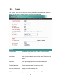
8.5.
System
The “System” allows users to setup the camera’s parameters, like camera name, data/time
setting. And also provide firmware upgrade and reset tools at this page.
System
Camera Name
The default camera name is “IC1500”. It is recommended to
name a meaningful name for the camera.
Login Name
Setup your administrator account’s login name. Default name is
“admin”
Password
Enter up to 4 digits password for the new user account.
Confirm Password
Enter the password again to confirm the setting.
Set Date/Time manually
Display the current Date and Time.
NTP Server
Synchronize the Date and Time with this NTP server.
50
Time Zone
Select the time zone that your camera put on.
NTP Server
Specify the IP Address of the NTP Server.
Upgrade Firmware
You can upgrade camera’s firmware via this function. Press the
browse button, find the correct firmware and press upgrade.
Reset to Factory Defaults
If you want to reset all the camera settings to default, click this
button.
Reboot Device
To reboot the NSC10 Network Camera, click “Reboot”.
LED Setting
There are four LEDs to indicate the status of NSC10 Network
Camera. If you wan to secure the camera from noticing, you can
turn off the LED light by clicking “LED Light OFF”. To turn on the
LED light, click “LED Light ON”.
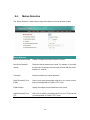
8.6.
Status
The “Status” shows the current firmware version, uptime, system time and IP information of
this camera.
51
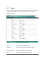
8.7.
Users
The “Users” allows users to add four user accounts which are able to view video from Camera
Viewer and Web Management. These users, unlike Administrator, are not allowed to
configure the camera.
User 1 / 2 / 3 / 4
User #
Enable or Disable the user number #.
Login
Enter the the login name to the camera.
Password
Enter up to 4 digits password for the new user account.
Confirm Password
Enter the password again to confirm the setting.
Apply
Click “Apply” to save the user account setting.
52
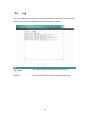
8.8.
Log
The “Log” allows users to monitor the device event and time. If you have trouble to use this
device, the log file will help administrator to know the status of device.
Log
Log screen
The screen will show event and event time of device.
Refresh
You can press “Refresh” button to refresh the log screen.
53
9. Frequently Asked Questions
Q1: What is a NSC10 Network Camera?
A: The NSC10 Network Camera is a standalone system connecting directly to an Ethernet or Fast
Ethernet network. It is different from the conventional PC Camera; the NSC10 Network Camera is an
all-in-one system with built-in CPU and web-based solutions providing a low cost solution that can
transmit high quality video images for monitoring. The NSC10 Network Camera can be managed
remotely, accessed and controlled from any PC/Notebook over the Intranet via a web browser or
camera viewer.
Q2: What algorithm is used to compress the digital image?
A: The NSC10 Network Camera utilizes MJPEG video compression technology to provide high quality
images. MJPEG is a standard for video compression and can be applied to various application
software.
Q3: Can I capture or record still images from the NSC10 Network Camera?
A: Yes, you are able to capture or record still images with the snapshot function from the Camera
Viewer application supplied with the NSC10 Network Camera CD-ROM.
Q4: What network cabling is required for the NSC10 Network Camera?
A: The NSC10 Network Camera uses Category 5 UTP Twisted-pair cable allowing 10 Base-T and 100
Base-T networking.
Q5: Can the NSC10 Network Camera be setup as a PC-cam on the computer?
A: No, the NSC10 Network Camera is used only on Ethernet and Fast Ethernet network.
Q6: Can the NSC10 Network Camera be connected on the network if it consists of only private IP
Addresses?
A: Yes, the NSC10 Network Camera can be connected to a LAN with private IP Addresses.
Q7: The focus on the NSC10 Network Camera is bad, how can I correct it?
A: Adjust the NSC10 Network Camera focus manually.
54
10.
Technical Specifications
Video specification
Max Resolution: 640 x 480 pixels
Sensor: 300K pixels 1/4" color CMOS sensor
Gain control: Automatic
Exposure: Automatic
White Balance: Automatic
Focal Length: 4.8 mm
Aperture: F=1.8
Image (Video Setting)
Image compression: MJPEG Image Video
Digital 24-bit Color
Frame rate: 30fps@QVGA, 20fps@VGA
Video resolution: 176 x 144, 320x240, 640x480
System Hardware
LAN Connector: One RJ-45 port to connect to 10/100Mbps Ethernet
Wireless: IEEE 802.11b/g(*Wireless Model Only)
LED Indicator: LAN LED (Green), WLAN LED (Amber), Power LED (Blue)
Power Supply: 12V / 1A (Wireless Model)
Power Supply: 12V / 1A (Wired Model)
HTTP/Utility
Includes easy-to-use Viewer & Recorder utility
Provides Admin utility & WEB browser Management
View multiple cameras simultaneously - Up to 16 cameras at a time
Manual/Schedule Record, Video Playback/Stop/Forward/Pause
Supports four additional user accounts for viewing camera
Auto sending Snap Shot by E-mail or FTP
Support DDNS and UPnP functions
Supports Windows 2000/XP/2003/Vista
Firmware Upgradeable
EMI & Safety
FCC, CE!
55
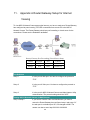
11.
Appendix A Router/Gateway Setup for Internet
Viewing
To view NSC10 Network Camera across the Internet, you have to make sure Router/Gateway
has configured to pass incoming TCP/UDP connections from remote PC to the NSC10
Network Camera. The Router/Gateway should set port forwarding or virtual server for the
connections. Please see the illustration as below.
Router/Gateway Port Forwarding/Virtual Server Setup
Name
Protocol
Port
LAN IP
Setup 1
TCP
80
192.168.2.3
Setup 2
TCP
4321
192.168.2.3
Port Definition
Setup 1
It is the port of Web port. You have to configure the protocol to
“TCP”.
Setup 2
It is the port of Video port. You have to configure the protocol to
“TCP”.
Setup 3
It is the port for NSC10 Network Camera and Administrator Utility
communication. The protocol setting should be “UDP”.
Viewing NSC10 Network Camera via Web Browser
Setup 1/Setup 2
If you want to view the video via Web Browser, you have to
ensure the Router/Gateway has configured setup1 and setup 2. If
the web port is not default port “80”, but changed to 8080. The
remote user has to enter http://203.30.212.82:8080.
56
Viewing NSC10 Network Camera via Camera Viewer Utility
Setup 2
If you want to use Camera Viewer Utility to view the camera,
please make sure the Router/Gateway has configured setup2.
Setup NSC10 Network Camera via Administrator Utility
Setup 3
If you want to use Administrator Utility to configure the NSC10
Network Camera via Internet, the Router/Gateway should
configure setup 3.
12.
Appendix B Set up WLAN step by step
Please follow the procedures below:
(1)
Please Check you Router Wireless settings, Suggesting Open System ( Disable
security ) first.
57
58
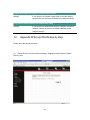
(2)
Please turn on DHCP Server of the Router for this testing.
59
(3)
Please reset the Wireless IP Camera settings to Factory Defaults by press the Reset
button over 8 seconds.
(4)
Please change your PC’s IP address to 192.168.2.xx (which xx from 10 to 253),
Netmask = 255.255.255.0
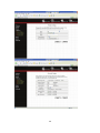
(5)
Please go to Web-Config WLAN section of the Wireless IP Camera.
Press Refresh button until you find the SSID you want in the list first!
Then select the Connect column of the SSID you want and select the Enable button of
Wireless Connection.
Press Apply button.
60
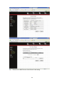
(6)
Please go to the LAN section of Web-Config.
Select DHCP and press Apply button.
Then you could close this IE browser window now.
(7)
Please UNPLUG the Ethernet Cable of the Wireless IP Camera now!
(8)
Wait for seconds then the Wireless IP Camera should be linked with the Wireless
Router.
61
(9)
Now you could let your PC to be connected with the Wireless Router.
(10)
In this case, if your PC’s DHCP Client IP is 192.168.8.101, then the Wireless IP Camera
must be
192.168.8.100, because Wireless IP Camera was got IP early then your PC.
(11)
You could go to the Web-Interface of the Wireless IP Camera.
62
13.
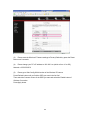
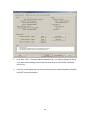
Appendix C Viewing via UPnP in Windows XP
When the UPnP function is enabled, the camera can be detected by UPnP compliant system
such as Windows XP. The camera will be displayed in the Neighborhood of Windows XP, so
you can directly double click the camera or right click the camera and select “Invoke” to view
the video through web browser.
63
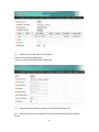
Enable UPnP in Windows XP SP2
If you can’t find the camera in the Neighborhood of Windows XP SP2 or you have seen the
following message when you double click the camera. You have to check if UPnP function is
blocked by the firewall. Please follow the steps below to enable it.
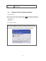
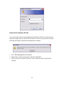
1. Go to “Start\Settings\Network Connections”.
2. Right click the “Local Area Connection” and select “Properties”.
3. In the “Local Area Connection Properties”, select “Advanced” option menu and click
“Settings”.
64
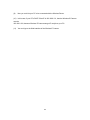
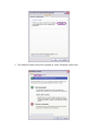
4. The “Windows Firewall” screen will be popped up, select “Exceptions” option menu.
65
5. Enable “UPnP Framework” from the “Programs and Services list” and click “Ok”.
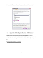
14.
Appendix D Configure Windows 2003 Server
Graphics Hardware Acceleration and DirectX are disabled by default on a Server
configuration to ensure maximum stability and uptime. But for any reason you need to enable
them to use DirectX enabled applications this section will guide you through on how you can
do it.
Enabling Graphics Hardware Acceleration
66
1.
Simply right click anywhere on your desktop and select Properties -> Settings tab ->
Advanced -> and finally, the Troubleshoot tab.
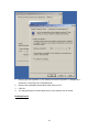
2.
Now move the Hardware acceleration slider across to Full
3.
Click OK
4.
You may experience a monitor black out for a few seconds, this is normal.
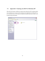
Enabling DirectX
67
5.
go to Start -> Run -> and type dxdiag followed by enter. You will get a dialog box asking
if you want to allow dxdiag to access the internet to check for valid WHQL certificates click on Yes.
6.
Let's click on the Display tab, now click on all three boxes to enable DirectDraw, Direct3D
and AGP Texture Acceleration.
68
INTellINeT NeTWoRK SolUTIoNS™ offers a complete line
of active and passive networking products.
Ask your local computer dealer for more information or visit
www.intellinet-network.com.
Copyright © INTELLINET NETWORK SOLUTIONS
All products mentioned are trademarks or registered trademarks of their respective owners.
69
![Internet Camera - [ [ [ ANSEL ] ] ]](http://vs1.manualzilla.com/store/data/005837536_1-ce302c6b28431aa03d9b92e65549b72a-150x150.png)