1
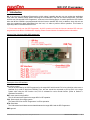
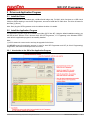
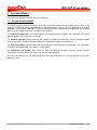
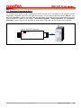
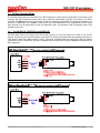
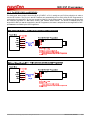
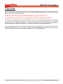
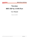
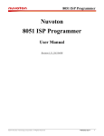
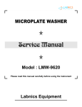
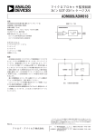
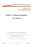
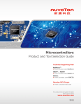
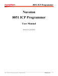
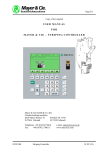
8051 ISP Programmer
Nuvoton
8051 ISP Programmer
User Manual
Revision 0.94b, 2009/6/1
©2009 Nuvoton Technology Corporation. All Rights Reserved.
Revision 0.94b, 2009/6/1
1
8051 ISP Programmer
Contents
Revision History ....................................................................................................... 3
1 Introduction ......................................................................................................... 4
2 Driver and Application Program .......................................................................... 5
2.1 Install the Driver .............................................................................................................................5
2.2 Install the Application Program ......................................................................................................5
2.2.1 Introduction to the GUI of the Application Program ..............................................................................5
3 Operation Modes................................................................................................. 6
3.1 On-line Operation Mode .................................................................................................................6
3.1.1 For W78E051D, W78E052D and W78E054D ......................................................................................7
3.1.2 For W78E(L)365A and W78E065A .......................................................................................................8
3.1.3 About the “Reset Control” .....................................................................................................................9
3.2 Download Programmer Mode ......................................................................................................10
3.3 Off-line Operation Mode ...............................................................................................................11
3.3.1 For W78E051D, W78E052D and W78E054D ....................................................................................11
3.3.2 For W78E(L)365A and W78E065A .....................................................................................................12
4 Note for ISP....................................................................................................... 13
©2009 Nuvoton Technology Corporation. All Rights Reserved.
Revision 0.94b, 2009/6/1
2
8051 ISP Programmer
Revision History
Revision
v0.92
v0.93
v0.94
v0.94b
Description
Date
(1) The first released version for beta-site test.
(2) Only W78E051D/ W78E052D/W78E054D are supported.
(1) Add “Reset Control” to the ISP interface.
(2) Add support of W78E(L)365A/W78E065A.
(1) Refine and correct this user manual.
(2) Fix the Programmer’s firmware bug:
The reset control becomes invalid if an error happens in “Update Target”.
(1) Modify the auto-FW-upgrade function for the Programmer.
(2) Add section 2.2.1, Introduction to the GUI of the Application Program, to this user
manual.
©2009 Nuvoton Technology Corporation. All Rights Reserved.
2009/5/15
2009/5/18
2009/5/22
2009/6/1
Revision 0.94b, 2009/6/1
3
8051 ISP Programmer
1 Introduction
ISP is the acronym of In-System Programming, which makes it possible that the user can update the application
code under the software control without removing the mounted MCU chip from the actual end product. The USBstick-like tool “Nuvoton 8051 ISP Programmer”, as shown in the following picture, is used to perform the ISP function
when the MCU’s LDROM is pre-programmed with the Nuvoton standard ISP code. In addition, since this tool can
save the programming data downloaded from the host, it is able to perform off-line operation. This feature is
especially useful in the field without the host.
*** To let users easily use the ISP Programmer, the 8051 products will have the Nuvoton standard ISP code preprogrammed in the MCU’s LDROM before shipping. Please contact Nuvoton for detailed product information.
Picture of the “Nuvoton 8051 ISP Programmer”
Description of the ISP Interface:
PL: pull-low control.
This pin is pulled low by the ISP Programmer for the target MCU which needs P4.3 to be pulled low when reset or
powered on (in order to boot from LDROM). Thus, the user needn’t be requested to pull low P4.3 in the target
system when using the ISP function. And, P4.3 is released for user’s normal function. (Refer to Section 3:
Hardware Connection.)
RST: reset control to target MCU.
The pin will send reset signal to the target MCU in ISP operation.
VCC: power supply from target system.
The power source for the ISP Programmer in off-line operation.
DTA: serial data.
The bi-directional serial data communicated between the target MCU and the ISP Programmer.
GND: ground.
©2009 Nuvoton Technology Corporation. All Rights Reserved.
Revision 0.94b, 2009/6/1
4
8051 ISP Programmer
2 Driver and Application Program
2.1 Install the Driver
This ISP Programmer is embedded with a USB-to-Serial bridge chip, PL-2303, which functions as a USB virtual
COM port. Before starting to use the ISP Programmer, we need to install the PL-2303 driver. The driver is located in
the folder [(1) Driver].
Note: Don't plug the ISP Programmer to the host before the driver is installed.
2.2 Install the Application Program
The application program setup file is located in the folder [(2) PC-site AP]. Using the default installation setting, you
will find the item “Nuvoton Tools \ Nuvoton 8051 ISP-ICP Programmer, v?.??” appearing in the Windows STARTmenu after the application program is successfully installed.
Note:
(1) v?.?? means the current version and may be upgraded in the future.
(2) ISP-ICP means this application program is used for both ISP Programmer and ICP (In-Circuit Programming)
Programmer, which will be developed in the near future.
2.2.1 Introduction to the GUI of the Application Program
©2009 Nuvoton Technology Corporation. All Rights Reserved.
Revision 0.94b, 2009/6/1
5
8051 ISP Programmer
3 Operation Modes
There are three operation modes for the ISP Programmer.
3.1 On-line Operation Mode
The following figures show the connection of the ISP Programmer between the target MCU and the host. In this
condition, the ISP Programmer cooperates with the PC-site application program. The user should select the wanted
“Part No.”, and then click “Load File” to load the Code Buffer with the code data to be programmed into the target
MCU. Four main software buttons are available in this condition:
(1) “Download Programmer”, which downloads the ISP Programmer with the data in the Code Buffer. This button
will keep disabled until “Load File” is performed.
(2) “Update Target MCU”, which triggers an ISP operation to update the target MCU. The ISP operation includes
program and verify. This button will keep disabled until “Download Programmer” is performed.
(3) “Verify Target MCU”, which compares the data programmed in the target MCU with the data in the Code Buffer.
This button will keep disabled until “Load File” is performed.
(4) “Programmer Information”, which shows the basic programming information currently saved in the ISP
Programmer, including Part No., file name, code size and code checksum.
The user can disconnect the ISP Programmer from the target MCU anytime to let the target MCU run the new
application code.
©2009 Nuvoton Technology Corporation. All Rights Reserved.
Revision 0.94b, 2009/6/1
6
8051 ISP Programmer
3.1.1 For W78E051D, W78E052D and W78E054D
For these parts, there is no need to have the I/O pin (P2.6/P2.7 or P4.3) be pulled low in order to use the ISP
function. Thus the PL-pin in the ISP interface is not used. The following two figures show the hardware connection
for “With Reset Control” and “Without Reset Control” configuration. The former is adopted when the target MCU’s
RST-pin can be controlled by the ISP Programmer; the latter is adopted when the target MCU’s RST-pin cannot be
controlled by the ISP Programmer.
With Reset Control (if the RST-pin can be controlled by the ISP Programmer)
PC
Target MCU
ISP Interface
RST
RST
VDD
VCC
P3.1
DTA
VSS
GND
Nuvoton 8051 ISP Programmer
X
(Less
than
30cm)
(PL)
RST
VCC
DTA
GND
ISP-Key
USB
Note:
(PL): Not used.
RST: Reset control to target MCU.
VCC: Power supply from target system.
DTA: Serial data between target MCU and Programmer.
GND: Ground
©2009 Nuvoton Technology Corporation. All Rights Reserved.
Revision 0.94b, 2009/6/1
7
8051 ISP Programmer
3.1.2 For W78E(L)365A and W78E065A
For these parts, there needs to have the I/O pin (P2.6/P2.7 or P4.3, usually we use P4.3) be pulled low in order to
use the ISP function. The PL-pin in the ISP interface can automatically pull low P4.3 when the ISP Programmer is
connected to the target MCU. So, the user needn’t pull low P4.3 in the target system. The following two figures show
the hardware connection for “With Reset Control” and “Without Reset Control” configuration. The former is adopted
when the target MCU’s RST-pin can be controlled by the ISP Programmer; the latter is adopted when the target
MCU’s RST-pin cannot be controlled by the ISP Programmer.
With Reset Control (if the RST-pin can be controlled by the ISP Programmer)
Target MCU
PC
ISP Interface
P4.3
(PL)
RST
RST
VDD
VCC
P3.1
DTA
VSS
GND
Nuvoton 8051 ISP Programmer
(Less
than
30cm)
(PL)
RST
VCC
DTA
GND
ISP-Key
USB
Note:
(PL): Pull-low control.
RST: Reset control to target MCU.
VCC: Power supply from target system.
DTA: Serial data between target MCU and Programmer.
GND: Ground
©2009 Nuvoton Technology Corporation. All Rights Reserved.
Revision 0.94b, 2009/6/1
8
8051 ISP Programmer
3.1.3 About the “Reset Control”
Normally, the target MCU’s RST-pin with RC reset circuitry can be controlled by the ISP Programmer. At this time,
the user may adopt the “With Reset Control” configuration for ISP operation. However, the RST-pin cannot be
controlled by the ISP Programmer when the RST-pin is connected to a reset IC (such as MAX810, ADM810, AIC810
and FP6810, etc.), the user should adopt the “Without Reset Control” configuration for ISP operation.
For the “With Reset Control” configuration, the ISP Programmer will always keep the target MCU in reset state until
the ISP operation is triggered, e.g. “Update Target” button is clicked or ISP-Key is pressed. At this time, the ISP
Programmer will release the target MCU to let it reboot from LDROM to run the ISP code. After ISP operation is
completed, the ISP Programmer keeps the target MCU in reset state again. The target MCU may be released and
run the new application code by disconnecting the ISP Programmer.
For the “Without Reset Control” configuration, to successfully let the target MCU boot from its LDROM to run the ISP
code, the user should follow the steps below.
Step1: Connect the ISP Programmer to the target MCU.
Step2: Connect the ISP Programmer to the host. (This step is only for on-line operation and may be exchanged with
Step1.)
Step3: Reset the target MCU manually, or turn off and then turn on again the target system.
Now, the target MCU will boot from its LDROM and run the ISP code.
©2009 Nuvoton Technology Corporation. All Rights Reserved.
Revision 0.94b, 2009/6/1
9
8051 ISP Programmer
3.2 Download Programmer Mode
The following figure shows the ISP Programmer to which only the host is connected. In this condition, the ISP
Programmer cooperates with the PC-site application program. The user should select the wanted “Part No.”, and
then click “Load File” to load the Code Buffer with the code data to be programmed into the target MCU. Three main
software buttons are available in this condition: “Download Programmer”, “Verify Target MCU” and “Programmer
Information”. Refer to the previous description of these buttons. This mode is for the following off-line operation.
PC
Nuvoton 8051 ISP Programmer
(PL)
RST
VCC
DTA
GND
ISP-Key
©2009 Nuvoton Technology Corporation. All Rights Reserved.
USB
Revision 0.94b, 2009/6/1
10
8051 ISP Programmer
3.3 Off-line Operation Mode
The following figures show the connection of the ISP Programmer to which only the target MCU is connected. In this
condition, the ISP Programmer should have been previously downloaded, and then can perform the off-line
operation. The ISP-Key is used to trigger an ISP operation to update the target MCU. The programming data are out
of the ISP Programmer. After updating is finished, the user may disconnect the ISP Programmer from the target
MCU anytime to let the target MCU run the new application code. This operation mode is especially useful in the
field without the host.
3.3.1 For W78E051D, W78E052D and W78E054D
For these parts, there is no need to have the I/O pin (P2.6/P2.7 or P4.3) be pulled low in order to use the ISP
function. Thus the PL-pin in the ISP interface is not used. The following two figures show the hardware connection of
“With Reset Control” and “Without Reset Control”. The former is adopted when the target MCU’s RST-pin can be
controlled by the ISP Programmer; the latter is adopted when the target MCU’s RST-pin cannot be controlled by the
ISP Programmer.
©2009 Nuvoton Technology Corporation. All Rights Reserved.
Revision 0.94b, 2009/6/1
11
8051 ISP Programmer
3.3.2 For W78E(L)365A and W78E065A
For these parts, there needs to have the I/O pin (P2.6/P2.7 or P4.3, usually we use P4.3) be pulled low in order to
use the ISP function. The PL-pin in the ISP interface can automatically pull low P4.3 when the ISP Programmer is
connected to the target MCU. So, the user needn’t pull low P4.3 in the target system. The following two figures show
the hardware connection of “With Reset Control” and “Without Reset Control”. The former is adopted when the
target MCU’s RST-pin can be controlled by the ISP Programmer; the latter is adopted when the target MCU’s RSTpin cannot be controlled by the ISP Programmer.
©2009 Nuvoton Technology Corporation. All Rights Reserved.
Revision 0.94b, 2009/6/1
12
8051 ISP Programmer
4 Note for ISP
For the ISP operation, the target MCU’s P3.1 pin is used as the DTA serial data pin. The best case is that P3.1
dedicates itself to the ISP operation. However, P3.1 can have its normal function when ISP is not requested as long
as the user conforms to the following rules:
(1) The state on P3.1 must be logic-1 when the target MCU is just powered on or reset.
(2) During the ISP operation, P3.1 cannot be pulled low by the other components connected to it.
It is because when the MCU boots from its LDROM and runs the Nuvoton standard ISP code, the MCU will sample
the state of P3.1 to determine the next action. If logic-0 is sampled, it means the ISP Programmer is connected to
the target MCU, so the MCU will continue to run the ISP code for further ISP operation; if logic-1 is sampled, the
MCU will immediately, within several instructions, re-boot from APROM to run user’s application code.
During the operating of ISP, P3.1 functions as bi-directional I/O for serial data transfer. It may output logic-1 or logic0 to the ISP Programmer, and receive logic-1 or logic-0 from the ISP Programmer. Thus the user should check if
there is any side effect on the other components connected to P3.1 during ISP operation.
©2009 Nuvoton Technology Corporation. All Rights Reserved.
Revision 0.94b, 2009/6/1
13