1
8051 ISP by COM Port
Nuvoton
8051 ISP by COM Port
User Manual
Revision 5.31, 2011/04/08
©2010 Nuvoton Technology Corporation. All Rights Reserved.
< Revision 5.31 >
1
8051 ISP by COM Port
Contents
Revision History ....................................................................................................... 3
1 Introduction ......................................................................................................... 4
2 Hardware............................................................................................................. 4
2.1 With an RS232 Transceiver in the Target System .........................................................................5
2.2 Without an RS232 Transceiver in the Target System ....................................................................6
2.3 Requirement on the MCU’s Operating Frequency .........................................................................7
3 Software .............................................................................................................. 8
3.1
3.2
3.3
3.4
Install the Application Program ......................................................................................................8
Introduction to the Application Program .........................................................................................8
Auto Synchronization of APROM/DataFlash Buffer .......................................................................9
Tool Project File (TPJ) .................................................................................................................10
4 Operation Steps ................................................................................................ 11
4.1 With Reset Control .......................................................................................................................11
4.2 Without Reset Control ..................................................................................................................11
5 Reset Control .................................................................................................... 12
©2010 Nuvoton Technology Corporation. All Rights Reserved.
< Revision 5.31 >
2
8051 ISP by COM Port
Revision History
Revision
v1.00
v2.00
v2.01
Description
Date
The first released version.
2009/07/15
(1) Fix some minor bugs in AP.
(2) Modify the handshaking mechanism in linking to target system.
(3) The data in Code Buffer are refreshed when the “Update 8051” or “Verify 8051”
button is clicked.
(1) Update the display of part numbers W78E051D, W78E052D and W78E054D to
become W78E(I)051D, W78E(I)052D and W78E(I)054D, respectively.
(2) Fix a minor bug in Nuvoton standard ISP code. (The ISP code version is changed to
v0201.)
2009/09/03
2009/09/22
v3.00
(1) Add new parts: N78E366A, N78E055A, N78E059A and N78E517A.
(2) Use the integrated PC-site application program of ISP-ICP Programmer.
2010/02/10
v4.00
Update the PC-site AP version to v4.00.
2010/04/01
v4.01
(1) Fix a minor bug in Nuvoton standard ISP code for W925EP01, N78E366A,
N78E055A, N78E059A and N78E517A. (The ISP code version is updated to v3.12.)
(2) Add a new part: W925EP01.
(3) Update the PC-site AP version to v4.01.
2010/06/15
v5.00
(1) Improve data security of the Nuvoton standard ISP code for N78E366A, N78E055A,
N78E059A and N78E517A. (The ISP code version is updated to v3.13.)
(2) Update the PC-site AP to v5.00. (The GUI display for "CONFIG Setting" becomes
more user-friendly.)
2010/08/13
v5.02
(1) Fix the HEX-to-BIN conversion error when the hex input file has a binary code size
more than 64K. (The application program is updated to v5.02.)
(2) Modify all the ISP codes to prevent from hanging in LDROM during powered on in an
RS-485 application. (The ISP code version is updated to v3.20.)
2010/11/15
v5.05
(1) Support Tool Project (TPJ) file for management of GUI setting.
(2) Fix the ISP code bug when using 3.6864MHz XTAL for ‘ISP by COM Port’ function.
(The ISP code version is updated to v3.21.)
(3) 3.6864MHz is the lowest XTAL frequency instead of 3MHz in v3.20.
2011/01/18
v5.31
(1) Fix some software bugs.
(2) The ISP code version is updated to v3.23.
2011/04/08
©2010 Nuvoton Technology Corporation. All Rights Reserved.
< Revision 5.31 >
3
8051 ISP by COM Port
1 Introduction
ISP is the acronym of In-System Programming, which makes it possible that the user can update the program
memory under the software control without removing the mounted MCU chip from the actual end product. For the
8051 MCU products, we provide an ISP solution through the PC’s COM port. As long as the Nuvoton standard ISP
code is pre-programmed in the MCU’s LDROM, the user can easily update the MCU’s APROM through the PC’s
COM port.
Note:
The ISP function can work only when the ISP code has resided in MCU’s LDROM. To let users easily use the ISP function, some
of the 8051 MCU products have the “Nuvoton Standard ISP Code” pre-programmed in LDROM and CONFIG bits properly
configured before shipping. Please contact Nuvoton for detailed product information. (The “Nuvoton Standard ISP Code” is also
included in the folder [(4) Nuvoton Standard ISP Code]. The user may program it by himself using a universal programmer.)
2 Hardware
To make the 8051 MCU boot from LDROM after reset to run the ISP code, some specific I/O pins need to be tied to
ground and the CONFIG needs to be properly configured. The following table shows the specific I/O pins and the
proper CONFIG setting used for booting from LDROM after reset. In addition, to directly connect to PC’s COM port,
there needs an RS232 transceiver (e.g. MAX232) in the target system. The following sub-sections will show the
hardware connection.
I/O Pins and CONFIG Bit for Booting from LDROM after Reset
Part No.
W78E(I)051D
W78E(I)052D
W78E(I)054D
W78E(I)058D
W78E(I)516D
W78E(L)365A
W78E065A
W78E858A
W78E(I)RD2A
W77E(L)516A
W77E(L)532A
W79E(L)632A
W79E(L)633A
W79E(L)648A
W79E(L)649A
W79E(L)658A
W79E(L)659A
W79E217A
W79E225A
W79E226A
W79E227A
I/O Pins Tied to Ground for
Booting from LDROM
CONFIG Setting for
Booting from LDROM
(Not Need)
“CBS”
Selected as LDROM
(Boot from LDROM)
P2.6 & P2.7 (for 40-pin package)
(Not Need)
P4.3 (for 44-pin package)
(Not Need)
P2.6 & P2.7 (for 40-pin package)
“Reboot P2.6/P2.7”
Enabled
P4.3 (for 44/68/100-pin package)
“Reboot P4.3”
Enabled
P3.6 & P3.7 (for 44-pin package)
P4.3 (for 48/100-pin package)
W79E201A
P4.0
W925EP01
P4.7
N78E366A
N78E055A
N78E059A
N78E517A
(Not Need)
©2010 Nuvoton Technology Corporation. All Rights Reserved.
“Reboot P3.6/P3.7”
Enabled
“Reboot P4.3”
Enabled
“Reboot P4.0”
Enabled
“Reboot P4.7”
Enabled
“CBS”
Selected as LDROM
(Boot from LDROM)
< Revision 5.31 >
4
8051 ISP by COM Port
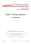
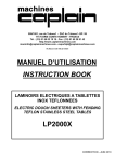
2.1 With an RS232 Transceiver in the Target System
In this design, each target system has an RS232 transceiver (e.g. MAX232) inside, and so only one RS232 cable is
needed during the ISP operation, as shown below.
Target System (with RS232 Transceiver)
VCC
C6
1u/16V
C3
10p
U2
/EA
XTAL1
X1
Fosc
C4
1u/16V
3
4
XTAL2
C5
1u/16V
UART
Interface
VCC
R1
47K
1
VCC
C1
2u
P3.0(RXD)
RST
P3.1(TXD)
RXD
TXD
VCC
P2.6
P2.7
5
TXD
11
10
RXD
12
9
C1+
16
U1
VCC
R2
10K
C2
10p
RS232
Transceiver
GND
8051 MCU
15
VCC
V+
V-
2
6
C7
1u/16V
C1-
C2-
R1_OUT
R2_OUT
R3 MAX232
4.7K
T1_OUT
T2_OUT
R1_IN
R2_IN
P1
GND
RI
DTR
CTS
TD
RTS
RD
DSR
DCD
C2+
T1_IN
T2_IN
RS232
Connector
14
7
13
8
5
9
4
8
3
7
2
6
1
Male DB9
R4
10K
Q1
2N3906
GND
To boot from LDROM.
(See Note 1)
RST
For reset control.
(See Note 2)
PC
COM Port
RS232 Cable
Note 1:
The I/O pins used for booting from LDROM may be P2.6&P2.7, P4.3, P3.6&P3.7, P4.0 or none.
(See the above table.)
Note 2:
For "With Reset Control" configuration, Q1, R3 and R4 are needed.
For "Without Reset Control" configuration, Q1, R3 and R4 are not needed.
©2010 Nuvoton Technology Corporation. All Rights Reserved.
< Revision 5.31 >
5
8051 ISP by COM Port
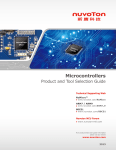
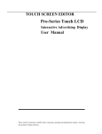
2.2 Without an RS232 Transceiver in the Target System
To save an RS232 transceiver (e.g. MAX232) built in each target system, the user may use the RS232 Cable
Adaptor with an RS232 transceiver inside, as shown below.
Target System (without RS232 Transceiver)
RS232 Cable Adaptor
VCC
C6
1u/16V
/EA
VCC
P2.6
XTAL1
R1
47K
X1
Fosc
P2.7
XTAL2
VCC
C1
2u
RST
P2.6
P2.7
To b oo t fro m LDRO M.
(Se e No te 1 )
RST
UART
In te rfa ce
RST
P3.0(RXD)
P3.1(TXD)
P2.6
P2.7
VCC
C4
1u/16V
R5
100
(PL)
Pulled low
4
C5
1u/16V
RST
VCC
P3.0
RXD
P3.1
TXD
GND
GND
3
5
TXD
11
10
RXD
12
9
VCC
C1+
2
6
C7
1u/16V
C2T1_IN
T2_IN
R1_OUT
R2_OUT
T1_OUT
T2_OUT
R1_IN
R2_IN
RS232
Connector
P1
GND
RI
DTR
CTS
TD
RTS
RD
DSR
DCD
C2+
Q1
2N3906
RST
V+
V-
C1-
R3 MAX232
4.7K
GND
16
U2
1
VCC
C2
10p
C3
10p
General
Connector
U1
R2
10K
RS232
Transceiver
GND
8051 MCU
15
VCC
14
7
13
8
5
9
4
8
3
7
2
6
1
Male DB9
R4
10K
Fo r re se t co n tro l.
(See No te 2)
PC
COM Port
RS232 Cable
Note 1:
The I/O pins used for booting from LDROM may be P2.6&P2.7, P4.3, P3.6&P3.7, P4.0 or none.
(See the above table.)
Note 2:
For "With Reset Control" configuration, Q1, R3 and R4 are needed.
For "Without Reset Control" configuration, Q1, R3 and R4 are not needed.
©2010 Nuvoton Technology Corporation. All Rights Reserved.
< Revision 5.31 >
6
8051 ISP by COM Port
2.3 Requirement on the MCU’s Operating Frequency
For ISP operation through COM port, there is no special restriction on the MCU’s operating frequency as long as the
frequency is higher than or equal to 3.6864MHz. The 8051 MCU will automatically choose a proper baudrate
according to its operating frequency to communicate with the host (PC). It is recommended that the user uses the
following specific frequencies: 3.6864MHz, 11.0592MHz, 18.432MHz, 22.1184MHz or 36.864MHz, for the 8051
MCU to generate a standard baudrate. All the listed frequencies can be used to generate an exact baudrate of
115200bps, which will shorten the data transmission time during ISP operation.
©2010 Nuvoton Technology Corporation. All Rights Reserved.
< Revision 5.31 >
7
8051 ISP by COM Port
3 Software
3.1 Install the Application Program
The application program setup file is contained in the folder [(2) Application Program]. Using the default installation
setting, you will find the item “Nuvoton Tools \ Nuvoton ISP-ICP Utility, v?.??” appearing in the Windows STARTmenu after the application program is successfully installed.
Note:
ISP-ICP means this application program is used for both the ISP Programmer and the ICP Programmer.
In addition, also for the ISP by COM Port.
3.2 Introduction to the Application Program
©2010 Nuvoton Technology Corporation. All Rights Reserved.
< Revision 5.31 >
8
8051 ISP by COM Port
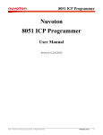
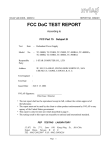
3.3 Auto Synchronization of APROM/DataFlash Buffer
The buffer contents will be automatically synchronized with the physical file in the hard disk when the function button
'Update Chip' is clicked, as shown below. So, the user needn’t manually reload the files for APROM buffer and
DataFlash buffer when the physical files are updated externally.
Click 'Update Chip' will make
the buffers synchronized.
Buffer Contents
Physical file in
the hard disk
©2010 Nuvoton Technology Corporation. All Rights Reserved.
< Revision 5.31 >
9
8051 ISP by COM Port
3.4 Tool Project File (TPJ)
The user may save all the GUI setting to the Tool Project (TPJ) file, and retrieve the GUI setting by loading the TPJ
file previously saved. It is much helpful to the user to manage a variety of the programming data by a project style.
Note: This feature is supported from revision v5.05.
©2010 Nuvoton Technology Corporation. All Rights Reserved.
< Revision 5.31 >
10
8051 ISP by COM Port
4 Operation Steps
4.1 With Reset Control
For the “With Reset Control” configuration, the user should follow the steps to do ISP.
Step 1: Connect the target system to PC’s COM port through an RS232 cable.
Step 2: Run the PC-site AP, select wanted part no., select correct COM port to which the target system is connected,
and load the code/data file into APROM/DataFlash Buffer.
Step 3: Click the “Update Chip” button when the target system is in power-on state.
Step 4: Now, the 8051 MCU will automatically reboot from LDROM, and will be successfully detected and updated.
Note: If possible, “With Reset Control” is strongly recommended for ISP operation.
4.2 Without Reset Control
For the “Without Reset Control” configuration, the user should follow the steps to do ISP.
Step 1: Connect the target system to PC’s COM port through an RS232 cable.
Step 2: Run the PC-site AP, select wanted part no., select correct COM port to which the target system is connected,
and load the code/data file into APROM/DataFlash Buffer.
Step 3: Click “Update Chip” button.
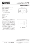
Step 4: Manually have the 8051 MCU reboot from LDROM during “Detect 8051…”, as shown in the following figure,
by the following two methods:
(1) send a reset pulse to the 8051 MCU’s RST-pin when the target system is in power-on state, or
(2) power off the target system and then power on again.
During detecting 8051, do the thing as Step4 describes.
Step 5: Now, the 8051 MCU will be successfully detected and updated.
Note:
(1) Step 4 shows the “Without Reset Control” is somewhat inconvenient for the user to have the 8051 MCU reboot
from LDROM. This is why we strongly recommend the user to adopt the “With Reset Control” configuration.
(2) If any failed condition happens, repeat steps 3 and 4.
©2010 Nuvoton Technology Corporation. All Rights Reserved.
< Revision 5.31 >
11
8051 ISP by COM Port
5 Reset Control
Normally, the 8051 MCU’s RST-pin with external RC reset circuit (see Figure 4a) can be controlled by the PNP
transistor Q1 (see the Figures in Sections 2.1 and 2.2). At this time, the user may adopt the “With Reset Control”
configuration for ISP operation. However, the RST-pin cannot be controlled when it is connected to a reset IC (such
as MAX810, ADM810, AIC810 and FP6810, etc., see Figure 4b). Now the user should adopt the “Without Reset
Control” configuration for ISP operation.
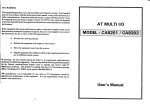
External RC Reset Circuit
The general external RC reset circuit is shown in Figure 4a. The resistance of R should be larger than 47KΩ to have
the RST-pin be successfully controlled by the PNP transistor. Normally, {47KΩ, 2.2uF} and {100KΩ, 1uF} are
recommended for {R, C}.
Figure 4a. External RC Reset Circuit
8051 MCU
External RC reset circuit
VDD
C
RST
R
GND
Reset Circuit with a Reset-IC
In this condition, the RST-pin cannot be controlled by the PNP transistor Q1.
Figure 4b. Reset Circuit with a Reset-IC
©2010 Nuvoton Technology Corporation. All Rights Reserved.
< Revision 5.31 >
12