1
8051 ISP Programmer
4 Note for ISP
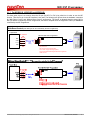
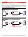
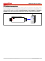
For the ISP operation, the target MCU’s P3.1 pin is used as the DTA serial data pin. The best case is that P3.1
dedicates itself to the ISP operation. However, P3.1 can have its normal function when ISP is not requested as long
as the user conforms to the following rules:
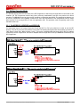
(1) The state on P3.1 must be logic-1 when the target MCU is just powered on or reset.
(2) During the ISP operation, P3.1 cannot be pulled low by the other components connected to it.
It is because when the MCU boots from its LDROM and runs the Nuvoton standard ISP code, the MCU will sample
the state of P3.1 to determine the next action. If logic-0 is sampled, it means the ISP Programmer is connected to
the target MCU, so the MCU will continue to run the ISP code for further ISP operation; if logic-1 is sampled, the
MCU will immediately, within several instructions, re-boot from APROM to run user’s application code.
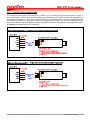
During the operating of ISP, P3.1 functions as bi-directional I/O for serial data transfer. It may output logic-1 or logic0 to the ISP Programmer, and receive logic-1 or logic-0 from the ISP Programmer. Thus the user should check if
there is any side effect on the other components connected to P3.1 during ISP operation.
©2009 Nuvoton Technology Corporation. All Rights Reserved.
Revision 0.94b, 2009/6/1
13