1
8051 ISP Programmer
Nuvoton
8051 ISP Programmer
User Manual
Revision 5.31, 2011/04/08
©2010 Nuvoton Technology Corporation. All Rights Reserved
< Revision 5.31 >
1
8051 ISP Programmer
Contents
Revision History ....................................................................................................... 3
1 Introduction ......................................................................................................... 4
2 Hardware............................................................................................................. 5
2.1
2.2
2.3
2.4
2.5
2.6
2.7
Type-1 Connection (No I/O Pins Used for Booting from LDROM) .................................................6
Type-2 Connection (P2.6 & P2.7 Used for Booting from LDROM) ................................................7
Type-3 Connection (P4.3 Used for Booting from LDROM) ............................................................8
Type-4 Connection (P3.6 & P3.7 Used for Booting from LDROM) ................................................9
Type-5 Connection (P4.0 Used for Booting from LDROM) ..........................................................10
Type-6 Connection (P4.7 Used for Booting from LDROM) ..........................................................11
Requirement on the XTAL Frequency..........................................................................................12
3 Software ............................................................................................................ 13
3.1 Install the Driver ...........................................................................................................................13
3.2 Install the Application Program ....................................................................................................13
3.2.1 Main GUI for the Application Program ................................................................................................13
3.2.2 GUI for ‘CONFIG Setting’....................................................................................................................14
3.2.3 GUI for ‘Programmer Information’ .......................................................................................................15
3.3 Auto Synchronization of APROM/DataFlash Buffer .....................................................................16
3.4 Tool Project File (TPJ) .................................................................................................................17
4 Operation Modes............................................................................................... 18
4.1 On-line Mode................................................................................................................................18
4.2 Download Programmer Mode ......................................................................................................18
4.3 Off-line Mode................................................................................................................................19
5 Reset Control .................................................................................................... 20
5.1 With Reset Control .......................................................................................................................21
5.2 Without Reset Control ..................................................................................................................21
6 Notes for the ISP Function ................................................................................ 22
6.1 Requirement on P3.1 ...................................................................................................................22
6.2 About the ISP Code .....................................................................................................................22
6.3 Compared with the ‘ICP’ ..............................................................................................................23
©2010 Nuvoton Technology Corporation. All Rights Reserved
< Revision 5.31 >
2
8051 ISP Programmer
Revision History
Revision
v1.00
v2.00
v2.01
Description
Date
The first formal released version.
2009/07/08
(1) Re-organize the function buttons on the GUI. The function of “Auto” is combined
with “Update 8051”.
(2) The data in Code Buffer are refreshed when the button “Update 8051” or “Verify
8051” is clicked.
(1) Update the picture of the ISP Programmer. (Section 1)
(2) Change the display of part numbers W78E051D, W78E052D and W78E054D to
W78E(I)051D, W78E(I)052D and W78E(I)054D, respectively.
(3) Fix a minor bug in Nuvoton standard ISP code. (The ISP code version is changed to
v0201.)
2009/09/03
2009/09/22
v3.00
Add new parts: W925EP01, N78E366A, N78E055A, N78E059A and N78E517A
2010/02/10
v4.00
Update the PC-site AP version to v4.00.
2010/04/01
v4.01
(1) Fix a minor bug in Nuvoton standard ISP code for W925EP01, N78E366A,
N78E055A, N78E059A and N78E517A. (The ISP code version is updated to v3.12.)
(2) Update the PC-site AP version to v4.01.
2010/06/15
v5.00
(1) Improve data security of the Nuvoton standard ISP code for N78E366A, N78E055A,
N78E059A and N78E517A. (The ISP code version is updated to v3.13.)
(2) Update the connection diagrams of Type-1~6. (Section 2.1~2.6)
(3) Add new sections. (Section 2.7, Section 6.2 and Section 6.3)
(4) Update the PC-site AP to v5.00. (The GUI display for "CONFIG Setting" becomes
more user-friendly.)
2010/08/13
v5.02
(1) Fix the HEX-to-BIN conversion error when the hex input file has a binary code size
more than 64K. (The application program is updated to v5.02.)
(2) Modify all the ISP codes to prevent from hanging in LDROM during powered on in
an RS-485 application. (The ISP code version is updated to v3.20.)
2010/11/15
v5.05
(1) Support Tool Project (TPJ) file for management of GUI setting.
(2) Fix the ISP code bug when using 3.6864MHz XTAL for ‘ISP by COM Port’ function.
(The ISP code version is updated to v3.21.)
2011/01/18
v5.31
(1) Fix some software bugs.
(2) The ISP code version is updated to v3.23.
2011/04/08
©2010 Nuvoton Technology Corporation. All Rights Reserved
< Revision 5.31 >
3
8051 ISP Programmer
1 Introduction
ISP is the acronym of In-System Programming, which makes it possible that the user can update the MCU’s
program memory under the software control without removing the mounted MCU chip from the actual end product.
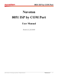
The USB-stick-like tool “8051 ISP Programmer”, as shown in the following picture, is used to perform the ISP
function when the MCU’s LDROM is pre-programmed with the Nuvoton Standard ISP Code and CONFIG bits are
properly configured. In addition, since this tool can save the programming data downloaded from the host, it is able
to perform the off-line operation. This feature is especially useful in the field without a host PC.
Note:
The ISP function can work only when the ISP code has resided in MCU’s LDROM. To let users easily use the ISP
function, some of the 8051 MCU products have the “Nuvoton Standard ISP Code” pre-programmed in LDROM and
CONFIG bits properly configured before shipping. Please contact Nuvoton for detailed product information. (The
“Nuvoton Standard ISP Code” is also included in the folder [(4) Nuvoton Standard ISP Code]. The user may program
it by himself using a universal programmer.)
Picture of the “8051 ISP Programmer”
The ISP Interface
PL: Pull-low control.
Some 8051 MCU parts need its special I/O pins to be tied to ground to boot from LDROM for ISP operation. Using
pull-low control can release these I/O pins for their normal function. In other words, these pins needn’t be tied to
ground in the target system but pulled low by the ISP Programmer for ISP operation.
RST: Reset control to the 8051 MCU.
The ISP Programmer will send reset signal to control the 8051 MCU for ISP operation.
VCC: Power supply from the target system. In off-line operation, the Programmer is powered by the target system.
DTA: Serial data to/from the 8051 MCU. (Single-wire Communication Interface)
GND: Ground.
©2010 Nuvoton Technology Corporation. All Rights Reserved
< Revision 5.31 >
4
8051 ISP Programmer
2 Hardware
According to the I/O pins used for booting from LDROM after reset, there are several connection types between the
8051 MCU and the ISP Programmer, as shown in the following table. Some parts don’t need any I/O pins, but need
CONFIG to be properly configured, such as W78E(I)051D, W78E(I)052D and W78E(I)054D. Some parts need only
I/O pins, such as W78E(I)058D, W78E(I)516D, etc. Some parts need not only I/O pins but also CONFIG properly
configured, such W78E(I)RD2A, W77E(L)516A, etc. The following sub-sections will show the connection diagrams
for these connection types.
I/O Pins and CONFIG Bit for Booting from LDROM after Reset
Part No.
I/O Pins Tied to Ground for
Booting from LDROM
CONFIG Setting for
Booting from LDROM
Connection Type
W78E(I)051D
W78E(I)052D
W78E(I)054D
(Not Need)
“CBS”
Selected as LDROM
Type-1
P2.6 & P2.7 (for 40-pin package)
(Not Need)
Type-2
P4.3 (for 44-pin package)
(Not Need)
Type-3
P2.6 & P2.7 (for 40-pin package)
“Reboot P2.6/P2.7”
Enabled
Type-2
P4.3 (for 44/68/100-pin package)
“Reboot P4.3”
Enabled
Type-3
W79E217A
W79E225A
W79E226A
W79E227A
P3.6 & P3.7 (for 44-pin package)
“Reboot P3.6/P3.7”
Enabled
Type-4
P4.3 (for 48/100-pin package)
“Reboot P4.3”
Enabled
Type-3
W79E201A
P4.0
“Reboot P4.0”
Enabled
Type-5
W925EP01
P4.7
“Reboot P4.7”
Enabled
Type-6
N78E366A
N78E055A
N78E059A
N78E517A
(Not Need)
“CBS”
Selected as LDROM
Type-1
W78E(I)058D
W78E(I)516D
W78E(L)365A
W78E065A
W78E858A
W78E(I)RD2A
W77E(L)516A
W77E(L)532A
W79E(L)632A
W79E(L)633A
W79E(L)648A
W79E(L)649A
W79E(L)658A
W79E(L)659A
©2010 Nuvoton Technology Corporation. All Rights Reserved
< Revision 5.31 >
5
8051 ISP Programmer
2.1 Type-1 Connection (No I/O Pins Used for Booting from LDROM)
In this type of connection, the PL-pin of the ISP interface is not used. The following figures show the hardware
connection for “With Reset Control” and “Without Reset Control” configuration. The former is adopted when the 8051
MCU’s RST-pin can be controlled by the ISP Programmer; the latter is adopted when the 8051 MCU’s RST-pin
cannot be controlled by the ISP Programmer. Refer to Section 5: Reset Control.
With Reset Control
Power
8051 MCU
ISP Interface
Nuvoton 8051 ISP Programmer
XTAL2
XTAL1
RST
RST
VDD
VCC
P3.1
DTA
VSS
GND
X
(Less
than
30cm)
(PL)
RST
VCC
DTA
GND
ISP-Key
Without Reset Control
Power
8051 MCU
Nuvoton 8051 ISP Programmer
ISP Interface
VDD
VCC
XTAL2
P3.1
DTA
XTAL1
VSS
GND
X
X
(Less
than
30cm)
©2010 Nuvoton Technology Corporation. All Rights Reserved
(PL)
RST
VCC
DTA
GND
ISP-Key
< Revision 5.31 >
6
8051 ISP Programmer
2.2 Type-2 Connection (P2.6 & P2.7 Used for Booting from LDROM)
In this type of connection, P2.6 and P2.7 are to be pulled low to let the 8051 MCU boot from LDROM after hardware
reset. The PL-pin in the ISP interface can automatically pull low P2.6 and P2.7 when the ISP Programmer is
connected to the 8051 MCU. So, the user needn’t always pull low P2.6 and P2.7 in the target system. The following
figures show the hardware connection for “With Reset Control” and “Without Reset Control” configuration. The
former is adopted when the 8051 MCU’s RST-pin can be controlled by the ISP Programmer; the latter is adopted
when the 8051 MCU’s RST-pin cannot be controlled by the ISP Programmer. Refer to Section 5: Reset Control.
With Reset Control
Power
8051 MCU
ISP Interface
P2.7
(PL)
P2.6
(PL)
RST
RST
VDD
VCC
XTAL2
P3.1
DTA
XTAL1
VSS
GND
Expanding
Adaptor
Nuvoton 8051 ISP Programmer
(PL)
RST
VCC
DTA
GND
(Less
than
30cm)
ISP-Key
Without Reset Control
Power
8051 MCU
ISP Interface
P2.7
(PL)
P2.6
(PL)
VDD
VCC
XTAL2
P3.1
DTA
XTAL1
VSS
GND
Expanding
Adaptor
Nuvoton 8051 ISP Programmer
X
(Less
than
30cm)
©2010 Nuvoton Technology Corporation. All Rights Reserved
(PL)
RST
VCC
DTA
GND
ISP-Key
< Revision 5.31 >
7
8051 ISP Programmer
2.3 Type-3 Connection (P4.3 Used for Booting from LDROM)
In this type of connection, P4.3 is to be pulled low to let the 8051 MCU boot from LDROM after hardware reset. The
PL-pin in the ISP interface can automatically pull low P4.3 when the ISP Programmer is connected to the 8051 MCU.
So, the user needn’t always pull low P4.3 in the target system. The following figures show the hardware connection
for “With Reset Control” and “Without Reset Control” configuration. The former is adopted when the 8051 MCU’s
RST-pin can be controlled by the ISP Programmer; the latter is adopted when the 8051 MCU’s RST-pin cannot be
controlled by the ISP Programmer. Refer to Section 5: Reset Control.
With Reset Control
Power
8051 MCU
XTAL2
XTAL1
ISP Interface
P4.3
(PL)
RST
RST
VDD
VCC
P3.1
DTA
VSS
GND
Nuvoton 8051 ISP Programmer
(Less
than
30cm)
©2010 Nuvoton Technology Corporation. All Rights Reserved
(PL)
RST
VCC
DTA
GND
ISP-Key
< Revision 5.31 >
8
8051 ISP Programmer
2.4 Type-4 Connection (P3.6 & P3.7 Used for Booting from LDROM)
In this type of connection, P3.6 and P3.7 are to be pulled low to let the 8051 MCU boot from LDROM after hardware
reset. The PL-pin in the ISP interface can automatically pull low P3.6 and P3.7 when the ISP Programmer is
connected to the 8051 MCU. So, the user needn’t always pull low P3.6 and P3.7 in the target system. The following
figures show the hardware connection for “With Reset Control” and “Without Reset Control” configuration. The
former is adopted when the 8051 MCU’s RST-pin can be controlled by the ISP Programmer; the latter is adopted
when the 8051 MCU’s RST-pin cannot be controlled by the ISP Programmer. Refer to Section 5: Reset Control.
With Reset Control
Power
8051 MCU
ISP Interface
P3.7
(PL)
P3.6
(PL)
RST
RST
VDD
VCC
XTAL2
P3.1
DTA
XTAL1
VSS
GND
Expanding
Adaptor
Nuvoton 8051 ISP Programmer
(PL)
RST
VCC
DTA
GND
(Less
than
30cm)
ISP-Key
Without Reset Control
Power
8051 MCU
ISP Interface
P3.7
(PL)
P3.6
(PL)
VDD
VCC
XTAL2
P3.1
DTA
XTAL1
VSS
GND
Expanding
Adaptor
Nuvoton 8051 ISP Programmer
X
(Less
than
30cm)
©2010 Nuvoton Technology Corporation. All Rights Reserved
(PL)
RST
VCC
DTA
GND
ISP-Key
< Revision 5.31 >
9
8051 ISP Programmer
2.5 Type-5 Connection (P4.0 Used for Booting from LDROM)
In this type of connection, P4.0 is to be pulled low to let the 8051 MCU boot from LDROM after hardware reset. The
PL-pin in the ISP interface can automatically pull low P4.0 when the ISP Programmer is connected to the 8051 MCU.
So, the user needn’t always pull low P4.0 in the target system. The following figures show the hardware connection
for “With Reset Control” and “Without Reset Control” configuration. The former is adopted when the 8051 MCU’s
RST-pin can be controlled by the ISP Programmer; the latter is adopted when the 8051 MCU’s RST-pin cannot be
controlled by the ISP Programmer. Refer to Section 5: Reset Control.
With Reset Control
Power
8051 MCU
XTAL2
XTAL1
ISP Interface
P4.0
(PL)
RST
RST
VDD
VCC
P3.1
DTA
VSS
GND
Nuvoton 8051 ISP Programmer
(Less
than
30cm)
©2010 Nuvoton Technology Corporation. All Rights Reserved
(PL)
RST
VCC
DTA
GND
ISP-Key
< Revision 5.31 >
10
8051 ISP Programmer
2.6 Type-6 Connection (P4.7 Used for Booting from LDROM)
In this type of connection, P4.7 is to be pulled low to let the 8051 MCU boot from LDROM after hardware reset. The
PL-pin in the ISP interface can automatically pull low P4.7 when the ISP Programmer is connected to the 8051 MCU.
So, the user needn’t always pull low P4.7 in the target system. The following figures show the hardware connection
for “With Reset Control” and “Without Reset Control” configuration. The former is adopted when the 8051 MCU’s
RST-pin can be controlled by the ISP Programmer; the latter is adopted when the 8051 MCU’s RST-pin cannot be
controlled by the ISP Programmer. Refer to Section 5: Reset Control.
With Reset Control
Power
8051 MCU
XTAL2
XTAL1
ISP Interface
P4.7
(PL)
RST
RST
VDD
VCC
P3.1
DTA
VSS
GND
Nuvoton 8051 ISP Programmer
(Less
than
30cm)
©2010 Nuvoton Technology Corporation. All Rights Reserved
(PL)
RST
VCC
DTA
GND
ISP-Key
< Revision 5.31 >
11
8051 ISP Programmer
2.7 Requirement on the XTAL Frequency
There is not any restriction on the XTAL frequency for ISP operation. All frequencies between 2MHz and 40MHz are
acceptable. The MCU will automatically build a proper transmission rate to communicate with the ISP Programmer
during ISP operation.
©2010 Nuvoton Technology Corporation. All Rights Reserved
< Revision 5.31 >
12
8051 ISP Programmer
3 Software
3.1 Install the Driver
This ISP Programmer has the USB-to-Serial bridge chip (PL-2303) built inside. When connected to host, it will
appear as a USB-to-Serial COM port in the System\Hardware\Device Manager. Before starting to use this
programmer, the user needs to install the driver in the host if the PL-2303 driver has never been installed in this host.
The user can also find this driver in the folder [(1) Driver].
Note: Don't plug the ISP Programmer to the host before the driver is installed.
3.2 Install the Application Program
The application program setup file is contained in the folder [(2) Application Program]. Using the default installation
setting, you will find the item “Nuvoton Tools \ Nuvoton ISP-ICP Utility, v?.??” appearing in the Windows STARTmenu after the application program is successfully installed.
Note: ISP-ICP means this application program is designed for both the ISP Programmer and the ICP Programmer.
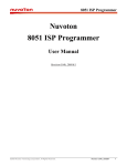
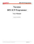
3.2.1 Main GUI for the Application Program
Select 'ISP'
for the ISP Programmer
Select wanted Part No.
Load file for APROM buffer
and DataFlash buffer (See Note)
Two things included:
(1) Download Programmer
(2) Update the MCU chip
Compare the MCU chip's
APROM with the code loaded
in the APROM buffer
Select
updated items
when
'Update Chip'
is clicked
Set CONFIG bits
Show the MCU chip's
CONFIG setting
Download the
current GUI's setting
into the Programmer
Click to show
APROM buffer
Click to show
DataFlash buffer
Show the
programming data
downloaded in the
Programmer
Information of
the loaded file
The COM port to which
the programmer is to be
connected
Processing
status
Note:
To load code file, click 'APROM Buffer', then click 'Load File'
To load data file, click 'DataFlash Buffer', then click 'Load File'
©2010 Nuvoton Technology Corporation. All Rights Reserved
< Revision 5.31 >
13
8051 ISP Programmer
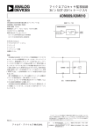
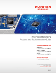
3.2.2 GUI for ‘CONFIG Setting’
For some 8051 MCU parts, such as N78E366A, N78E055A, N78E059A and N78E517A, the CONFIG bits can be
updated by the ISP Programmer, as shown below.
©2010 Nuvoton Technology Corporation. All Rights Reserved
< Revision 5.31 >
14
8051 ISP Programmer
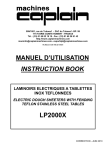
3.2.3 GUI for ‘Programmer Information’
To check the programming data downloaded in the Programmer, click the ‘Programmer Information’ button when the
Programmer is connected to PC. Note the ‘CONFIG Setting’ dialog box appears only when the CONFIG bits are to
be updated.
Downloaded CONFIG setting
©2010 Nuvoton Technology Corporation. All Rights Reserved
< Revision 5.31 >
15
8051 ISP Programmer
3.3 Auto Synchronization of APROM/DataFlash Buffer
The buffer contents will be automatically synchronized with the physical file in the hard disk when the function button
'Download Programmer', 'Update Chip' or 'Verify Chip' is clicked, as shown below. So, the user needn’t manually
reload the files for APROM buffer and DataFlash buffer when the physical files are updated externally.
These function buttons will
make the buffers synchronized.
Buffer contents
Physical file in
the hard disk
©2010 Nuvoton Technology Corporation. All Rights Reserved
< Revision 5.31 >
16
8051 ISP Programmer
3.4 Tool Project File (TPJ)
The user may save all the GUI setting to the Tool Project (TPJ) file, and retrieve the GUI setting by loading the TPJ
file previously saved. It is much helpful to the user to manage a variety of the programming data by a project style.
Note: This feature is supported from revision v5.05.
Save GUI setting
to a TPJ file
Restore GUI setting
from a TPJ file
©2010 Nuvoton Technology Corporation. All Rights Reserved
< Revision 5.31 >
17
8051 ISP Programmer
4 Operation Modes
4.1 On-line Mode
The system diagram for On-line Mode is shown below. In this mode, both the host and 8051 MCU are connected.
The user may directly update the 8051 MCU or download the programming data into the ISP Programmer for using
in the Off-line Mode. After updating the 8051 MCU, the user may disconnect the ISP Programmer to let the 8051
MCU run the new application code.
4.2 Download Programmer Mode
The system diagram for Download Programmer Mode is shown below. In this mode, only the host is connected.
The user may download the programming data into the ISP Programmer for using in the Off-line Mode.
©2010 Nuvoton Technology Corporation. All Rights Reserved
< Revision 5.31 >
18
8051 ISP Programmer
4.3 Off-line Mode
The system diagram for Off-line Mode is shown below. In this mode, only the 8051 MCU is connected. This mode is
especially useful in the field without the host. After the ISP Programmer has been downloaded, it can perform the
off-line operation. Press the ISP-Key to trigger an ISP operation to update the 8051 MCU. After updating the 8051
MCU, the user may disconnect the ISP Programmer to let the 8051 MCU run the new application code.
©2010 Nuvoton Technology Corporation. All Rights Reserved
< Revision 5.31 >
19
8051 ISP Programmer
5 Reset Control
Normally, the 8051 MCU’s RST-pin with external RC reset circuit (see Figure 5a) can be controlled by the ISP
Programmer. At this time, the user may adopt the “With Reset Control” configuration for ISP operation. However, the
RST-pin cannot be controlled by the ISP Programmer when the RST-pin is connected to a reset IC (such as
MAX810, ADM810, AIC810 and FP6810, etc., see Figure 5b). Now the user should adopt the “Without Reset
Control” configuration for ISP operation.
External RC Reset Circuit
The general external RC reset circuit is shown in Figure 5a. The resistance of R should be larger than 47KΩ to have
the RST-pin be successfully controlled by the ISP Programmer. Normally, {47KΩ, 2.2uF} and {100KΩ, 1uF} are
recommended for {R, C}.
Figure 5a. External RC Reset Circuit
8051 MCU
External RC reset circuit
VDD
C
RST
R
GND
Reset Circuit with a Reset-IC
In this condition, the RST-pin cannot be controlled by the ISP Programmer.
Figure 5b. Reset Circuit with a Reset-IC
8051 MCU
VDD
Reset IC (active High)
VCC
RESET
RST
GND
GND
©2010 Nuvoton Technology Corporation. All Rights Reserved
< Revision 5.31 >
20
8051 ISP Programmer
5.1 With Reset Control
For the “With Reset Control” configuration, the ISP Programmer will always keep the 8051 MCU in reset state until
the ISP operation is triggered, such as “Update Chip” button is clicked or ISP-Key is pressed. At this time, the ISP
Programmer will release the 8051 MCU to let it reboot from LDROM to run the ISP code. After ISP operation is
completed, the ISP Programmer keeps the 8051 MCU in reset state again. When the ISP Programmer is
disconnected from the 8051 MCU, the 8051 MCU will automatically reboot from APROM to run the new application
code. With reset control, the user may do the ISP operation as long as the ISP Programmer is connected to 8051
MCU when the 8051 MCU is in powered-on state.
Note: “With Reset Control” is strongly recommended for ISP operation.
5.2 Without Reset Control
For the “Without Reset Control” configuration, to successfully let the 8051 MCU boot from LDROM to run the ISP
code, the user should follow the steps listed below.
Step 1: Connect the ISP Programmer to the 8051 MCU.
Step 2: Connect the ISP Programmer to the host. (This step is only for On-line Mode and may be exchanged with Step1.)
Step 3: Make the 8051 MCU boot from LDROM by the following two methods:
(1) Send reset a reset pulse to the RST-pin, or (2) power off the and power on again.
Step 4: Now, the 8051 MCU will boot from LDROM and start to run the ISP code for ISP operation.
Note:
Step 3 shows the “Without Reset Control” is somewhat inconvenient for the user to have the 8051 MCU boot from
LDROM. That is why we strongly recommend the user to adopt the “With Reset Control” configuration.
©2010 Nuvoton Technology Corporation. All Rights Reserved
< Revision 5.31 >
21
8051 ISP Programmer
6 Notes for the ISP Function
6.1 Requirement on P3.1
During ISP operation, the 8051 MCU’s P3.1 behaves as ‘DTA’ (serial data). When ISP is not requested, P3.1 can
function as its normal general purpose I/O pin as long as P3.1 conforms to the following requirements:
* The state of P3.1 must be logic-1 before the MCU is just released from reset condition.
* During the ISP operation, P3.1 cannot be pulled low by the other components connected to it.
It is because when the MCU boots from its LDROM and starts to run the Nuvoton standard ISP code, the MCU will
sample P3.1 to determine the next action. If logic-0 is sampled, it means the ISP Programmer is connected, and the
MCU will stay in LDROM for further ISP operation; if logic-1 is sampled, the MCU will automatically re-boot from
APROM (by internal software reset) to run the user’s application code.
During the operating of ISP, P3.1 functions as bi-directional I/O for serial data transfer. It may output logic-1 or logic0 to the ISP Programmer, and receive logic-1 or logic-0 from the ISP Programmer. Thus the user should check if
there is any side effect on the other components connected to P3.1 during ISP operation.
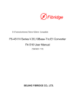
The following flow chart shows how the MCU determines to cooperate with ISP Programmer or to reboot from
APROM when the MCU starts to run the Nuvoton standard ISP code in LDROM.
Start
MCU boots from LDROM
Check if P3.1=0?
Y
Keep running in LDROM, and
cooperate with the ISP Programmer
N
MCU re-boots from APROM
to run the user's application code
6.2 About the ISP Code
For the 8051 MCU products with ISP function, there are two program memories: one is APROM and the other is
LDROM. APROM contains the user's application code for normal operation while LDROM contains the ISP code
(cooperating with the ISP Programmer) for updating of APROM. To use the ISP Programmer to update APROM, the
ISP code should always reside in LDROM. If the ISP code disappears from LDROM because of accidentally being
erased by a universal programmer, the ISP function will become always failed. To recover the ISP function, please
use a universal programmer to program the Nuvoton standard ISP code into LDROM, and have its CONFIG setting
properly configured (cf. Section 2).
Why is the ISP code easily/accidentally erased by a universal programmer? Because the LDROM is also erased
along with the APROM if the user uses a universal programmer to program APROM. So, we strongly recommend
the user to use the ISP Programmer to program APROM in the beginning of getting the MCU sample with ISP code
inside. Don't use any universal programmer to program APROM unless the ISP function won’t be used.
©2010 Nuvoton Technology Corporation. All Rights Reserved
< Revision 5.31 >
22
8051 ISP Programmer
6.3 Compared with the ‘ICP’
The difference between ISP (In-System Programming) and ICP (In-Circuit Programming) is that ISP is implemented
by software control of MCU itself while ICP is implemented by hardware control. So, before updating the MCU chip,
ISP needs a software code (the ISP-code) pre-programmed in MCU’s LDROM to function as software control while
ICP doesn’t need any software code pre-programmed.
©2010 Nuvoton Technology Corporation. All Rights Reserved
< Revision 5.31 >
23