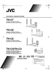
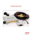
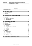
1
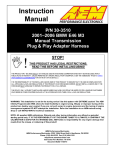
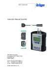
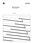
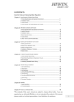
Bosch ECUs
INTRODUCTION
AIM has developed special applications for many of the most common ECUs: by special
applications we mean user-friendly systems which allow to connect quite easily your ECU
to our hi-tech data loggers (EVO3 Pro/Pista, MXL Strada/Pista/ Pro05): users need only
to install harness between – for example - MXL and the ECU unit.
Once connected, the MXL displays (and records, depending on the model) values like
RPM, engine load, throttle position (TPS), air and water temperatures, battery voltage,
speed, gear, lambda value (air/fuel ratio) and analog channels of your choice.
All AIM data loggers include - free of charge - our free Race Studio 2 software, a powerful
tool to configure the system and analyze recorded data on your PC.
Please note: once your ECU is connected to the AIM Logger, you need to set in the logger
configuration in Race Studio 2 software.
Bosch ECUs
User Manual
Release 1.00
INDEX
Chapter 1 – BOSCH – MS3 ............................................................................................................. 3 1.1 – CAN Communication Set-Up.......................................................................................... 3 1.2 – Connection to AIM data loggers ........................................................................................... 4 1.3 – BOSCH – MS3 Protocol ....................................................................................................... 5 1.4 – Configure your data logger with Race Studio 2 software ..................................................... 6 Chapter 2 – BOSCH – MS3 SPORT (pinout not available)........................................................... 8 2.1 – CAN Communication Set-Up ............................................................................................... 8 2.2 – BOSCH – MS3 SPORT Protocol ......................................................................................... 9 2.3 – Configure your data logger with Race Studio 2 software ................................................... 10 Chapter 3 – BOSCH - MS4 ............................................................................................................ 12 3.1 – CAN Communication Set-Up ............................................................................................. 12 3.2 – Connection to AIM data loggers ......................................................................................... 12 3.3 – Bosch – MS4 Protocol........................................................................................................ 13 3.4 – Configure your data logger with Race Studio 2 software ................................................... 14 Chapter 4 – BOSCH–MS4 for Porsche 997 ................................................................................. 16 4.1 – CAN Communication Set-Up ............................................................................................. 16 4.2 – Connection to AIM data loggers ......................................................................................... 16 4.3 – BOSCH MS4 997 Protocol ................................................................................................. 17 4.4 – Configure your data logger with Race Studio 2 software ................................................... 18 Chapter 5 – BOSCH - MS4 SPORT .............................................................................................. 20 5.1 – CAN Communication Set-Up ............................................................................................. 20 5.2 – Connection to AIM data loggers ......................................................................................... 20 5.3 – Bosch MS4 Protocol .......................................................................................................... 22 5.4 – Configure your data logger with Race Studio 2 software ................................................... 23 Chapter 6 – BOSCH – PORSCHE 911 (Mod.997) - Pinout not available ................................... 25 6.1 – Connection to AIM Data logger .......................................................................................... 25 6.2 – BOSCH PORSCHE 911 (Mod. 997) protocol .................................................................... 25 6.3 – Configure your data logger with Race Studio 2 software ................................................... 26 Chapter 7 – BOSCH – PORSCHE 997 GT3 (street car) .............................................................. 28 7.1 – CAN Communication Set-Up ............................................................................................. 28 7.2 – Connection to AIM Data logger .......................................................................................... 28 7.3. – BOSCH PORSCHE 997 GT3 protocol .............................................................................. 29 7.4 – Configure your data logger with Race Studio 2 software ................................................... 30 www.aim-sportline.com
Bosch ECUs
User Manual
Release 1.00
Chapter 8 – BOSCH MOTRONIC MED 9.1– SEAT LEON CUP ................................................... 32 8.1 – CAN Communication Set-Up ............................................................................................. 32 8.2 – Connection to AIM data loggers ......................................................................................... 32 8.3– BOSCH SEAT LEON CUP Protocol ................................................................................... 33 8.4 – Configure your data logger with Race Studio 2 software ................................................... 34 www.aim-sportline.com
2
Bosch ECUs
User Manual
Release 1.00
Chapter 1 – BOSCH – MS3
1.1 – CAN Communication Set-Up
The ECU has a digital communication CAN Protocol used to communicate parameters to a
data logger or to configure the ECU itself.
The following diagram shows the connections between the ECU and the logger:
This ECU can be installed on Porsche 911- 996 GT3 Cup and Porsche 911- 997 GT3 Cup
cars.
www.aim-sportline.com
3
Bosch ECUs
User Manual
Release 1.00
Porsche 911-996 GT3 Cup (models from 2002 to 2005) and Porsche 997 GT3 Cup ECUs
are equipped with a 22 pins Deutsch connector, shown below, with an external red ring.
Connector Part Number is RP 3759339.
1.2 – Connection to AIM data loggers
To connect AIM logger to the ECU, please connect the cable labelled CAN+ with pin 4 of
the ECU and the cable labelled CAN- with pin 16 of the ECU.
Pin
Function
4
CAN+
16
CAN-
Comments
Please note: To power AIM logger directly from the ECU use pin 15 of the ECU (+12V)..
www.aim-sportline.com
4
Bosch ECUs
User Manual
Release 1.00
1.3 – BOSCH – MS3 Protocol
Channels shown on AIM data loggers via CAN Protocol with Bosch are:
ECU_1
BOSCH_RPM
RPM VALUE
ECU_2
BOSCH_SPEED1
SPEED1
ECU_3
BOSCH_SPEED2
SPEED2
ECU_4
BOSCH_OIL_PRESS
OIL PRESSURE
ECU_5
BOSCH_FUEL_PRESS
FUEL PRESSURE
ECU_6
BOSCH_ATM _PRESS
AIR PRESSURE
ECU_7
BOSCH_FUEL_TEMP
FUEL TEMPERATURE
ECU_8
BOSCH_OIL_TEMP
OIL TEMPERATURE
ECU_9
BOSCH_ENGINE_TEMP ENGINE TEMPERATURE
ECU_10
BOSCH_AIR_TEMP
AIR TEMPERATURE
ECU_11
BOSCH_THROTT_ANG
THROTTLE ANGLE
ECU_12
BOSCH_IGNIT_ANG
IGNITION ANGLE(FASE)
ECU_13
BOSCH_AIR_CHARGE
ENGINE LOAD
ECU_14
BOSCH_INJEC_TIME1
INJECTION TIME1
ECU_15
BOSCH_INJEC_TIME2
INJECTION TIME2
ECU_16
BOSCH_LAMBDA1
LAMBDA1
ECU_17
BOSCH_LAMBDA2
LAMBDA 2
ECU_18
BOSCH_LAM_CONTR1
LAMBDA CONTROLLER1
ECU_19
BOSCH_LAM_CONTR2
LAMBDA CONTROLLER2
ECU_20
BOSCH_FUEL_USED
USED FUEL
ECU_21
***NOT AVAILABLE***
ECU_22
BOSCH_GEAR
GEAR NUMBER
ECU-23
BOSCH_VBATT
BATTERY VOLTAGE
www.aim-sportline.com
5
Bosch ECUs
User Manual
Release 1.00
1.4 – Configure your data logger with Race Studio 2 software
In order to ensure the communication between AIM data loggers and the ECU it is
necessary to configure the logger following this procedure:
•
run Race Studio 2 software
•
press AIM System manager button
•
a choice panel appears: select the logger to connect to the ECU
•
press “GO TO” button.
www.aim-sportline.com
6
Bosch ECUs
User Manual
Release 1.00
System manager window shown here below appears:
•
Press “New button”
•
New configuration window appears (shown here above); fill it in as follows
•
Logger type: the logger to connect to the ECU
•
ECU Manufacturer: BOSCH
•
ECU Model: MS3
•
Click on OK button
www.aim-sportline.com
7
Bosch ECUs
User Manual
Release 1.00
Chapter 2 – BOSCH – MS3 SPORT (pinout not available)
2.1 – CAN Communication Set-Up
The ECU has a digital communication CAN Protocol used to communicate parameters to a
data logger or to configure the ECU itself.
BOSCH MS3 SPORT ECU
www.aim-sportline.com
8
Bosch ECUs
User Manual
Release 1.00
2.2 – BOSCH – MS3 SPORT Protocol
Channels shown on AIM data loggers via CAN Protocol with Bosch are:
ECU_1
MS3_RPM
RPM VALUE
ECU_2
MS3_SPEED
SPEED VALUE
ECU_3
MS3_TPS
THROTTLE POSITION SENSOR
ECU_4
MS3_GEAR
GEAR NUMBER
ECU_5
MS3_WH_SPD_FL
WHEEL SPEED FRONT LEFT
ECU_6
MS3_WH_SPD_FR
WHEEL SPEED FRONT RIGHT
ECU_7
MS3_WH_SPD_RL
WHEEL SPEED REAR LEFT
ECU_8
MS3_WH_SPD_RR
WHEEL SPEED REAR RIGHT
ECU_9
MS3_LAM1
LAMBDA1
ECU_10
MS3_LAM2
LAMBDA2
ECU_11
MS3_OIL_P
OIL PRESSURE
ECU_12
MS3_ATM_P
AIR PRESSURE
ECU_13
MS3_FUEL_P
FUEL PRESSURE
ECU_14
MS3_CRANK_P
CRANK PRESSURE
ECU_15
MS3_OIL_T
OIL TEMPERATURE
ECU_16
MS3_ATM_T
AIR TEMPERATURE
ECU_17
MS3_FUEL_T
FUEL TEMPERATURE
ECU_18
MS3_ECT
WATER TEMPERATURE
ECU_19
MS3_EX-T1
EXHAUST GAS TEMPERATURE1
ECU_20
MS3_EX-T2
EXHAUST GAS TEMPERATURE2
ECU_21
MS3_BATTVOLT
BATTERY VOLTAGE
www.aim-sportline.com
9
Bosch ECUs
User Manual
Release 1.00
2.3 – Configure your data logger with Race Studio 2 software
In order to ensure the communication between AIM data loggers and the ECU it is
necessary to configure the logger following this procedure:
•
run Race Studio 2 software
•
press AIM System manager button
•
a choice panel appears: select the logger to connect to the ECU
•
press “GO TO” button.
www.aim-sportline.com
10
Bosch ECUs
User Manual
Release 1.00
System Manager window shown here below appears:
•
Press “New button”
•
New configuration window appears (shown here above); fill it in as follows
•
Logger type: the logger to connect to the ECU
•
ECU Manufacturer: BOSCH
•
ECU Model: MS3
•
Click on OK button
www.aim-sportline.com
11
Bosch ECUs
User Manual
Release 1.00
Chapter 3 – BOSCH - MS4
3.1 – CAN Communication Set-Up
The ECU has a digital communication CAN Protocol used to communicate parameters to a
data logger or to configure the ECU itself.
BOSCH MS4 ECU
3.2 – Connection to AIM data loggers
Due to the fact that this ECU model has two CAN outputs, it is necessary to try two
connections to find out the one that is enabled to work properly with AIM logger. The table
here below shows two couples of pins : 60(CAN+)/58(CAN-) and 79(CAN+)/77(CAN-).
Connect cable labelled CAN+ with ECU CAN+ and cable labelled CAN- with ECU CAN -.
PIN
FUNCTION
COMMENTS
60 /58
CAN+/CANCAN 1
79/77
CAN+/CANCAN 2
WARNING: never connect pins belonging to different couples (like pin 60 with pin 77
for example).
www.aim-sportline.com
12
Bosch ECUs
User Manual
Release 1.00
3.3 – Bosch – MS4 Protocol
Channels shown on AIM data loggers via CAN Protocol with Bosch MS4 Protocol are:
ECU_1
BOSCH_RPM
RPM VALUE
ECU_2
BOSCH_VEHICLE_SPEED SPEED VEHICLE
ECU_3
BOSCH_TPS
THROTTLE POSITION SENSOR
ECU_4
BOSCH_IGNIT_ANG
IGNITION ANGLE
ECU_5
BOSCH_ENGINE_TEMP
ENGINE TEMPERATURE
ECU_6
BOSCH_OIL_TEMP
OIL TEMPERATURE
ECU_7
BOSCH_FUEL_TEMP
FUEL TEMPERATURE
ECU_8
BOSCH_AIR_TEMP
AIR TEMPERATURE
ECU_9
BOSCH_GEAR
GEAR NUMBER
ECU_10
BOSCH_GEAR_OIL_P
GEAR OIL TEMPERATURE
ECU_11
BOSCH_FUEL_PRESS
FUEL PRESSURE
ECU_12
BOSCH_WATER_PRESS
WATER PRESSURE
ECU_13
BOSCH_ATM_PRESS
AIR PRESSURE
ECU_14
BOSCH_OIL_PRESS
OIL PRESSURE
ECU_15
BOSCH_LAMBDA1
LAMBDA1
ECU_16
BOSCH_LAMBDA2
LAMBDA2
ECU_17
BOSCH_AFR1
AFR LAMBDA1
ECU_18
BOSCH_AFR2
AFR LAMBDA2
ECU_19
BOSCH_INJEC_TIME1
INJECTION TIME1
ECU_20
BOSCH_INJECT_TIME2
INJECTION TIME2
ECU_21
BOSCH_FUEL_USED
FUEL COMSUMPTION
ECU_22
BOSCH_ACC_X
ACCELEROMETER VALUE(X)
ECU_23
BOSCH_ACC_Y
ACCELEROMETER VALUE(Y)
ECU_24
BOSCH_ACC_Z
ACCELEROMETER VALUE(Z)
ECU_25
BOSCH_BREAK_P_R
BRAKE PRESSURE REAR
ECU_26
BOSCH_BREAK_P_F
BRAKE PRESSURE FRONT
ECU_27
BOSCH_EXHAUST_GAS
EXHAUST GAS TEMPERATURE
ECU_28
BOSCH_SPEED_F_L
SPEED FRONT LEFT
ECU_29
BOSCH_SPEED_F_R
SPEED FRONT RIGHT
ECU_30
BOSCH_SPEED_R_L
SPEED REAR LEFT
ECU_31
BOSCH_SPEED_R_R
SPEED REAR RIGHT
www.aim-sportline.com
13
Bosch ECUs
User Manual
Release 1.00
3.4 – Configure your data logger with Race Studio 2 software
In order to ensure the communication between AIM data loggers and the ECU it is
necessary to configure the logger following this procedure:
•
run Race Studio 2 software
•
press AIM System manager button
•
a choice panel appears: select the logger to connect to the ECU
•
press “GO TO” button.
www.aim-sportline.com
14
Bosch ECUs
User Manual
Release 1.00
System Manager window shown here below appears:
•
Press “New button”
•
New configuration window appears (shown here above); fill it in as follows
•
Logger type: the logger to connect to the ECU
•
ECU Manufacturer: BOSCH
•
ECU Model: MS4
•
Click on OK button
www.aim-sportline.com
15
Bosch ECUs
User Manual
Release 1.00
Chapter 4 – BOSCH–MS4 for Porsche 997
4.1 – CAN Communication Set-Up
The ECU has a digital communication CAN Protocol used to communicate parameters to
the data logger. The data logger communicates with the ECU through a dedicate
connector.
BOSCH MS4 997 ECU
4.2 – Connection to AIM data loggers
Due to the fact that this ECU model has two CAN outputs, it is necessary to try two
connections to find out the one that is enabled to work properly with AIM logger. The table
here below shows two couples of pins : 60(CAN+)/58(CAN-) and 79(CAN+)/77(CAN-).
Connect cable labelled CAN+ with ECU CAN+ and cable labelled CAN- with ECU CAN -.
PIN
FUNCTION
COMMENTS
60 /58
CAN+/CANCAN 1
79/77
CAN+/CANCAN 2
WARNING: never connect pins belonging to different couples (like pin 60 with pin 77
for example).
www.aim-sportline.com
16
Bosch ECUs
User Manual
Release 1.00
4.3 – BOSCH MS4 997 Protocol
Channels shown on AIM data loggers via CAN Protocol with Bosch Porsche 997 are:
ECU_1
ECU_2
ECU_3
ECU_4
ECU_5
ECU_6
ECU_7
ECU_8
ECU_9
ECU_10
ECU_11
ECU_12
ECU_13
ECU_14
ECU_15
ECU_16
ECU_17
ECU_18
ECU_19
ECU_20
ECU_21
ECU_22
ECU_23
ECU_24
ECU_25
ECU_26
ECU_27
ECU_28
ECU_29
ECU_30
ECU_31
ECU_32
ECU_33
ECU_34
ECU_35
ECU_36
ECU_37
ECU_38
ECU_39
ECU_40
ECU_41
ECU_42
ECU_43
ECU_44
ECU_45
BOSCH_RPM
BOSCH_SPEED1
BOSCH_SPEED2
BOSCH_OIL_PRESS
BOSCH_FUEL_PRESS
BOSCH_ATM_PRESS
BOSCH_FUEL_TEMP
BOSCH_OIL_TEMP
BOSCH_ENGINE_TEMP
BOSCH_AIR_TEMP
BOSCH_THROTT_ANG
BOSCH_IGNIT._ANG
BOSCH_AIR_CHARGE
BOSCH_INJEC_TIME1
BOSCH_INJECT_TIME2
BOSCH_LAMBDA1
BOSCH_LAMBDA2
BOSCH_GEAR_POT_C
BOSCH_GEAR_SHIFT_C
BOSCH_FUEL_USED
BOSCH_FUEL_LAP
BOSCH_GEAR
BOSCH_VBATT
BOSCH_MAPPOS
BOSCH_PWAT
BOSCH_PCRANNK
BOSCH_PCLUTCH
BOSCH_SPEED_F_L
BOSCH_SPEED_F_R
BOSCH_SPEED_R_L
BOSCH_SPEED_R_R
BOSCH_ACC_X
BOSCH_ACC_Y
BOSCH_ACC_Z
BOSCH_STEER
BOSCH_YAV
BOSCH_GEARV
BOSCH_BVMAX_REQV
BOSCH_BVMAX
BOSCH_BSHIFTLAMP_ON
BOSCH_BKNOCK
BOSCH_BMAIL
BOSCH_BOIL
BOSCH_BLCA
BOSCH_BASR
RPM VALUE
SPEED1
SPEED2
OIL PRESSURE
FUEL PRESSURE
AIR PRESSURE
FUEL TEMPERATURE
OIL TEMPERATURE
ENGINE TEMPERATURE
AIR TEMPERATURE
THROTTLE ANGLE
IGNITION ANGLE
ENGINE LAOD
INJECTION TIME1
INJECTION TIME2
LAMBDA PROBE 1
LAMBDA PROBE 2
GEAR POTENZIOMETER
N.A.
FUEL CONSUMPTION
FUEL CONSUMPTION PER LAP
GEAR NUMBER
VOLTAGE BATTERY
MAP POSITION
WATER PRESSURE
CRANK PRESSURE
CLUTCH PRESSURE
SPEED FRONT LEFT
SPEED FRONT RIGHT
SPEED REAR LEFT
SPEED REAR RIGHT
ACCELEROMETER VALUE(X)
ACCELEROMETER VALUE(Y)
ACCELEROMETER VALUE(Z)
STEERING ANGLE
GYRO
GEAR VOLTAGE
WARNING SENSOR
WARNING SENSOR
GEAR FLASH
KNOCKING SENSOR
WARNING SENSOR
WARNING SENSOR
WARNING SENSOR
WARNING SENSOR
www.aim-sportline.com
17
Bosch ECUs
User Manual
Release 1.00
4.4 – Configure your data logger with Race Studio 2 software
In order to ensure the communication between AIM data loggers and the ECU it is
necessary to configure the logger following this procedure:
•
run Race Studio 2 software
•
press AIM System manager button
•
a choice panel appears: select the logger to connect to the ECU
•
press “GO TO” button.
www.aim-sportline.com
18
Bosch ECUs
User Manual
Release 1.00
System Manager window shown here below appears:
•
Press “New”
•
New configuration window appears (shown here above); fill it in as follows
•
Logger type: the logger to connect to the ECU
•
ECU Manufacturer: BOSCH
•
ECU Model: MS4_997
•
Click on “OK”
www.aim-sportline.com
19
Bosch ECUs
User Manual
Release 1.00
Chapter 5 – BOSCH - MS4 SPORT
5.1 – CAN Communication Set-Up
The ECU has a digital communication CAN Protocol used to communicate parameters to a
data logger, or to configure the ECU itself.
MS4 SPORT ECU
5.2 – Connection to AIM data loggers
Due to the fact that this ECU model has two CAN outputs, it is necessary to try two
connections to find out the one that is enabled to work properly with AIM logger. The table
here below shows two couples of pins : 60(CAN+)/58(CAN-) and 79(CAN+)/77(CAN-).
Connect cable labelled CAN+ with ECU CAN+ and cable labelled CAN- with ECU CAN -.
PIN
FUNCTION
COMMENTS
60 /58
CAN+/CANCAN 1
79/77
CAN+/CANCAN 2
WARNING: never connect pins belonging to different couples (like pin 60 with pin 77
for example).
www.aim-sportline.com
20
Bosch ECUs
User Manual
Release 1.00
Here below the wiring diagram of Bosch MS4 Sport is shown.
To zoom this image please click on:
http://www.aim-sportline.com/download/doc/eng/Wiring_Diagram_MS4_Sport.pdf
www.aim-sportline.com
21
Bosch ECUs
User Manual
Release 1.00
5.3 – Bosch MS4 Protocol
Channels shown on AIM data loggers via CAN Protocol with Bosch MS4 Customer
Protocol are:
ECU_1
MS4_RPM
RPM VALUE
ECU_2
MS4_SPEED
SPEED VALUE
ECU_3
BOSCH_TPS
THROTTLE POSITION SENSOR
ECU_4
BOSCH_GEAR
GEAR NUMBER
ECU_5
BOSCH_WH_SPD_FL
WHEEL SPEED FRONT LEFT
ECU_6
BOSCH_WH_SPD_FR
WHEEL SPEED FRONT RIGHT
ECU_7
BOSCH_ WH-SPD_RL
WHEEL SPEED REAR LEFT
ECU_8
BOSCH_WH_SPD_RR WHEEL SPEED REAR RIGHT
ECU_9
BOSCH_LAM1
LAMBDA1
ECU_10
BOSCH_LAM2
LAMBDA2
ECU_11
BOSCH_OIL_P
OIL PRESSURE
ECU_12
BOSCH_ATM_P
AIR PRESSURE
ECU_13
BOSCH_FUEL_P
FUEL PRESSURE
ECU_14
BOSCH_CRANK_P
CRANK PRESSURE
ECU_15
BOSCH_P1
PRESSURE 1
ECU_16
BOSCH_OIL_T
OIL TEMPERATURE
ECU_17
BOSCH_ATM_T
AIR TEMPERATURE
ECU_18
BOSCH_FUEL_T
FUEL TEMPERATTURE
ECU_19
BOSCH_ECT
WATER TEMPERATURE
ECU_20
BOSCH_EX_T1
EXHAUST GAS TEMPERATURE1
ECU_21
BOSCH_EX_:T2
EXHAUST GAS TEMPERATURE2
ECU_22
BOSCH_LAMBDA T1
LAMBDA TEMPERATURE1
ECU_23
BOSCH_LAMBDA T
LAMBDA 2
ECU_24
BOSCH_BATTVOLT
BATTERY VOLTAGE
ECU_25
BOSCH_MIL
MALFUNCTIONING INDICATOR LAMP
ECU_26
BOSCH_OIL_SW
OIL SWITCH
www.aim-sportline.com
22
Bosch ECUs
User Manual
Release 1.00
5.4 – Configure your data logger with Race Studio 2 software
In order to ensure the communication between AIM data loggers and the ECU it is
necessary to configure the logger following this procedure:
•
run Race Studio 2 software
•
press AIM System manager button
•
a choice panel appears: select the logger to connect to the ECU
•
press “GO TO” button.
www.aim-sportline.com
23
Bosch ECUs
User Manual
Release 1.00
System manager window shown here below appears:
•
Press “New button”
•
New configuration window appears (shown here above); fill it in as follows
•
Logger type: the logger to connect to the ECU
•
ECU Manufacturer: BOSCH
•
ECU Model: MS4 SPORT
•
Click on OK button
www.aim-sportline.com
24
Bosch ECUs
User Manual
Release 1.00
Chapter 6 – BOSCH – PORSCHE 911 (Mod.997) - Pinout not
available
6.1 – Connection to AIM Data logger
The ECU has a digital communication CAN Protocol used to communicate parameters to a
datalogger, or to configure itself. This ECU can be installed on Porsche 911 (997).
Here below all models compatible with Porsche 991(997) CAN protocol are listed:
2004
CARRERA
CARRERA S
CARRERA CABRIO
CARRERA S CABRIO
2005
CARRERA 4
CARRERA 4S
CARRERA 4 CABRIO
CARRERA 4 S CABRIO
2006
997 TARGA
997 TARGA 4 S
6.2 – BOSCH PORSCHE 911 (Mod. 997) protocol
Channels shown on AIM data loggers via CAN Protocol with Bosch Porsche 911 (Mod.
997) are:
ECU_1
P997_RPM
RPM
ECU_2
P997_SPEEDFL
VEHICLE SPEED – FRONT LEFT WHEEL
ECU_3
P997_SPEEDFR
VEHICLE SPEED – FRONT RIGHT WHEEL
ECU_4
P997_SPEEDRL
VEHICLE SPEED – REAR LEFT WHEEL
ECU_5
P997_SPEEDRR
VEHICLE SPEED – REAR RIGHT WHEEL
ECU_6
P997_PPS
PEDAL POSITION SENSOR
ECU_7
P997_ENGINE_TEMP
ENGINE TEMPERATURE
ECU_8
P997_STEER_ANGLE
STEERING ANGLE
ECU_9
P997_FREE
CUSTOM CHANNEL
ECU_10
P997_FREE
CUSTOM CHANNEL
ECU_11
P997_FREE
CUSTOM CHANNEL
ECU_12
P997_FREE
CUSTOM CHANNEL
www.aim-sportline.com
25
Bosch ECUs
User Manual
Release 1.00
6.3 – Configure your data logger with Race Studio 2 software
In order to ensure the communication between AIM data loggers and the ECU it is
necessary to configure the logger following this procedure:
•
run Race Studio 2 software
•
press AIM System manager button
•
a choice panel appears: select the logger to connect to the ECU
•
press “GO TO”
www.aim-sportline.com
26
Bosch ECUs
User Manual
Release 1.00
System manager window appears:
•
Press “New”
•
New configuration window appears (shown here below); fill it in as follows
•
Logger type: the logger to connect to the ECU
•
ECU Manufacturer: BOSCH
•
ECU Model: Porsche_991 (997)
•
Click on OK
www.aim-sportline.com
27
Bosch ECUs
User Manual
Release 1.00
Chapter 7 – BOSCH – PORSCHE 997 GT3 (street car)
7.1 – CAN Communication Set-Up
The ECU we call Bosch Porsche 997 GT3 is an ECU made by Bosch manufacturer and
generally installed on Porsche 911 cars (997 GT3 road car model). This ECU has a Can
Protocol and is equipped with a 40 pins connector called “D” and used to communicate
with an external data logger as well as to configure the ECU itself.
PORSCHE 997 GT3 ECU
7.2 – Connection to AIM Data logger
To connect AIM logger to the ECU, connect cable labelled CAN+ of AIM wiring to pin D36
of the ECU (CAN HIGH) and cable labelled CAN– of AIM wiring to pin D37 of the ECU
(CAN LOW), as in the table below:
Pin
Function
D36
CAN +
D37
CAN -
Comments
www.aim-sportline.com
28
Bosch ECUs
User Manual
Release 1.00
7.3. – BOSCH PORSCHE 997 GT3 protocol
Channels shown on AIM data loggers via CAN Protocol with Bosch Porsche 997 GT3
(Road car) are:
ECU_1
BOSCH_RPM
RPM VALUE
ECU_2
BOSCH_TPS
THROTTLE POSITION SENSOR
ECU_3
BOSCH_PPS
PEDAL POSITION SENSOR
ECU_4
BOSCH_WH _SPD_FL
WHEEL SPEED LEFT WHEEL
ECU_5
BOSCH_WH_SPD_FR
WHEEL SPEED RIGHT WHEEL
ECU_6
BOSCH_WH_SPD_RL
WHEEL SPEED RIGHT WHEEL
ECU_7
BOSCH_WH_SPD_RR
WHEEL SPEED LEFT WHEEL
ECU_8
BOSCH_BOOST_P
BOOST PRESSURE
ECU_9
BOSCH_ECT
WATER TEMPERATURE
ECU_10
BOSCH_OIL_T
OIL TEMPERATURE
ECU_11
BOSCH_OIL_P
OIL PRESSURE
ECU_12
BOSCH_STEERANGLE ANGLE OF STEERING
ECU_13
BOSCH_STEERSPEED SPEED OF STEERING
ECU_14
BOSCH_BRAKE_SW
BRAKE SWITCH
ECU_15
BOSCH_GEAR
GEAR NUMBER
ECU_16
BOSCH_FUEL_LEVEL
FUEL LEVEL
www.aim-sportline.com
29
Bosch ECUs
User Manual
Release 1.00
7.4 – Configure your data logger with Race Studio 2 software
In order to ensure the communication between AIM data loggers and the ECU it is
necessary to configure the logger following this procedure:
•
run Race Studio 2 software
•
press AIM System manager button
•
a choice panel appears: select the logger to connect to the ECU
•
press “GO TO” .
www.aim-sportline.com
30
Bosch ECUs
User Manual
Release 1.00
System manager window appears:
•
Press “New”
•
New configuration window appears (shown here below); fill it in as follows
•
Logger type: the logger to connect to the ECU
•
ECU Manufacturer: BOSCH
•
ECU Model: 997_GT3
•
Click on “OK”
www.aim-sportline.com
31
Bosch ECUs
User Manual
Release 1.00
Chapter 8 – BOSCH MOTRONIC MED 9.1– SEAT LEON CUP
8.1 – CAN Communication Set-Up
The ECU has a digital communication CAN Protocol and is equipped with a 94 pins
connector (named A11) used to communicate parameters to the data logger. The data
logger communicates with the ECU through a dedicated connector.
8.2 – Connection to AIM data loggers
Connect cable labelled CAN+ of AIM wiring to pin 68 (CAN+) of A11 connector and cable
labelled CAN- of AIM wiring to pin 67 (CAN-) of A11 connector .
SEAT LEON CUP
Here below the A11 Connector pinout:
www.aim-sportline.com
32
Bosch ECUs
User Manual
Release 1.00
8.3– BOSCH SEAT LEON CUP Protocol
Channels shown on AIM data loggers via CAN Protocol with Bosch for Seat Leon Cup are:
ECU_1
BOSCH_RPM
RPM
ECU_2
BOSCH_FOOT_THROTTLE
PEDAL POSITION SENSOR
ECU_3
BOSCH_THROTTLE
THROTTLE POSITION SENSOR
ECU_4
BOSCH_SPEED_FL
SPEED FRONT RIGHT
ECU_5
BOSCH_SPEED_FR
SPEED FRONT LEFT
ECU_6
BOSCH_SPEED_RL
SPEED REAR LEFT
ECU_7
BOSCH_SPEED_RR
SPEED REAR RIGHT
ECU_8
BOSCH_WATER _TEMP
WATER TEMPERATURE
ECU_9
BOSCH_AIR_TEMP
AIR TEMPERATURE
ECU_10
BOSCH_TURBO_PRESS
TURBO PRESSURE
ECU_11
BOSCH_TURBO_PRESS_HF
ECU_12
BOSCH_TURBO _PRESS_LF
ECU_13
BOSCH_BOOST_PRESS
ECU_14
BOSCH_FUEL_PRESS_L
ECU_15
BOSCH_FUEL_PRESS_HFUEL PRESS HIGH
ECU_16
BOSCH_LAMBDA
ECU_17
BOSCH_AIRFLOW
ECU_18
BOSCH_GEAR
ECU_19
BOSCH_GEAR_LEVER_POS
ECU_20
BOSCH_GEAR_LEVER_POS2
ECU_21
BOSCH_FAILURE
FUEL PRESS LOW
LAMBDA VALUE
GEAR NUMBER
SYSTEM FAILURE
www.aim-sportline.com
33
Bosch ECUs
User Manual
Release 1.00
8.4 – Configure your data logger with Race Studio 2 software
In order to ensure the communication between AIM data loggers and the ECU it is
necessary to configure the logger following this procedure:
•
run Race Studio 2 software
•
press AIM System manager button
•
a choice panel appears: select the logger to connect to the ECU
•
press “GO TO”
www.aim-sportline.com
34
Bosch ECUs
User Manual
Release 1.00
System manager window shown appears:
•
Press “New”
•
New configuration window appears (shown here below); fill it in as follows
•
Logger type: the logger to connect to the ECU
•
ECU Manufacturer: BOSCH
•
ECU Model: Seat_Leon_Cup
•
Click on “OK”
www.aim-sportline.com
35