1
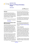
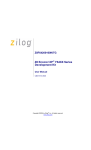
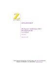
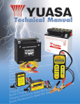
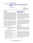
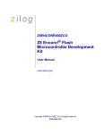
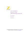
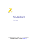
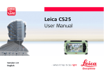
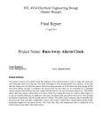
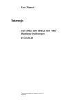
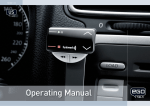
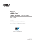
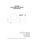
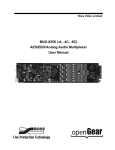
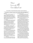
Application Note Z8 Encore!®-Based Battery Charger AN013703-0708 Abstract Features This Application Note demonstrates Zilog’s Z8 Encore!®-based battery charger that charges various rechargeable batteries in a fast, efficient, and safe manner. The features of Z8 Encore! are as follows: All the important rechargeable battery types, Sealed Lead Acid (SLA), Nickel Cadmium (NiCd), Nickel Metal Hydride (NiMH), and Lithium Ion (Li-Ion), are addressed in this Application Note. The Z8 Encore!-based charger manages each battery type according to its individual charging profile. Note: The source code file associated with this application note, AN0137SC01.zip is available for download at www.zilog.com. Product Overview Z8 Encore! products are based on the new 8-bit eZ8 CPU, and introduce Flash memory to Zilog’s extensive line of 8-bit microcontrollers unit (MCU). The Flash in-circuit programming capability allows for faster development time and program changes in the field. The new eZ8 core maintains backward compatibility with Zilog’s popular Z8® MCU. Featuring Zilog’s high performance register-to-register based architecture (eZ8), the new Z8 Encore! MCUs combine a fast 20 MHz core, up to 64 KB of Flash memory, up to 4 KB of linear register SRAM, and an extensive array of on-chip peripherals. These peripherals make Z8 Encore! suitable for a variety of applications including motor control, security systems, home appliances, personal electronic devices, and sensors. • New high-performance 20 MHz eZ8 CPU • Up to 64 KB Flash memory with in-circuit programming capability • Up to 4 KB register SRAM • 12-channel, 10-bit analog-to-digital converter (ADC) • Two full-duplex UARTs • Two Infrared Data Association (IrDA) compliant endecs • SPI and I2C ports • Four 16-bit timers with capture, compare, and PWM capability • Watchdog Timer (WDT) with internal RC oscillator • 3-channel DMA • Up to 60 I/O pins • 24 interrupts with configurable priority • On-Chip Debugger • Voltage Brownout protection (VBO) • Power-On Reset (POR) The Z8 Encore! CPU is capable of a nominal 10 MIPs throughput at 20 MHz. The 4 KB SRAM extends the Z8 Encore!’s reach to a wider range of applications. The 10-bit sigma/delta ADC provides high measurement resolution, and the SPI, UART, and I2C interfaces can be used concurrently. The versatile DMA controllers can be configured in many useful combinations to free the CPU from performing unnecessary data transfer overhead. Copyright ©2008 by Zilog®, Inc. All rights reserved. www.zilog.com Z8 Encore!®-Based Battery Charger Discussion A discussion on designing a battery charger is presented in this section. For further details, see Reference on page 8. Theory of Operation When designing a battery charger, the following aspects are considered: • Power control techniques to suit different battery types and capacities. • Charging and charge termination techniques to avoid overcharging, thus facilitating fast charging. • Safety techniques to ensure safe operation throughout the charging process. Setpoint (VSET /I SET ) + - Error These aspects are discussed in the following section. Power Control Techniques At the core of a battery charger is the DC–DC converter that acts as a regulated power source. The charger hardware is capable of regulating its output in various modes, such as constant voltage, constant current, or constant voltage with a current limit. The charger can be viewed as a control system in itself. In Figure 1, an initial setpoint is a charger output value chosen by you. In a battery charger, the type and capacity of the battery is the determinant of the mode of operation—namely, a constant current source or a constant voltage source. It also determines the required current and voltage setpoints. These setpoints can be expressed as ISET or VSET. Control Signal (PWM) Controller Actuator (Buck Converter) Output (VOUT /I OUT) Feedback Signal (VFB /IFB) Feedback Circuits Figure 1. Feedback Control System The feedback circuits displayed in Figure 1 measures actual output. The difference between the initial setpoint and the actual value (feedback signal) is called an error. The controller generates a control signal according to the magnitude and direction of the error. It minimizes the steady state error and also responds quickly to transient fluctuations during input or output. Controllers usually work at lower power levels and therefore require an external actuator to generate the appropriate output. In a battery charger, the actuator is a step-down DC–DC converter, also known as a buck converter. The buck converter converts a higher DC voltage to a lower one depending on the Pulse Width Modulated (PWM) control signal generated by the controller. The frequency of the PWM signal is maintained at a constant while the width of the pulse or the duty cycle of the signal varies. This variation is reflected as a change in voltage and/or current at the output. Controllers are differentiated according to the way they handle errors generated during regulation of AN013703-0708 Page 2 of 17 Z8 Encore!®-Based Battery Charger the system output (in the case of a charger, these errors are either voltage or current errors). In a proportional controller, the actual value and the set value are compared, and the resulting error value is used. In such a system, there exists the possibility of a steady state error, which is a drawback for the proportional controller. Adding an integral component to the proportional controller eliminates this steady state error. where Kp and Ki are the proportional and integral constants, respectively. The equation for a proportional plus integral (PI) controller is: Charging and Charge Termination Techniques υ ( t ) = ( k1 × e ( t ) + k2 × ∫ e ( t ) dt ) To be useful for a microcontroller-based (discrete) system, the integral is approximated by a running sum of the error signal. Thus, an equation can be expressed as follows called Equation 1: ⎛ ⎞ k–1 υ [ k ] = ⎜ C1 × e [ k ] + C2 × ∑ e [ j ]⎟ ⎜ ⎟ j=0 ⎝ ⎠ where C1 and C2 are constants. Equation 1 is the position algorithm. A better representation for Equation 1 is described in Equation 2, as follows: ⎛ ⎞ k–2 ⎜ υ [ k – 1 ] = ⎜ C1 × e [ k – 1 ] + C2 × ∑ e [ j ]⎟⎟ j=0 ⎝ ⎠ Subtracting Equation 2 from Equation 1 and rearranging the terms yields Equation 3, as follows: υ [ k ] – υ [ k – 1 ] = ( Kp × e [ k ] + Ki × e [ k – 1 ] ) AN013703-0708 Equation 3 is the velocity algorithm. It is a convenient expression, as only the incremental change in the manipulated variable is calculated. For a detailed discussion on controllers, see Reference on page 8. Different battery types require different charging methods. The basic charging methods are the constant current and constant voltage charging. The NiCd and NiMH batteries are charged using the constant current method, whereas the SLA and LiIon batteries are charged via the constant voltage method. An on/off current limiter is required when performing constant voltage charging. These charging methods are based on the type of battery and the present state of charge for that battery. In a constant current method of charging, fast charging occurs when the charging current equals the rated battery capacity, C. Fast charging requires constant monitoring of battery parameters and precise termination techniques. It is therefore important to know when to terminate charging. The behavior of different batteries near full charge varies and demands different termination techniques. The most common termination techniques are the negative ΔV, zero ΔV, and the absolute battery voltage, all of which are based on battery types. For more information, see Appendix D— Battery Technology on page 15. Safety Techniques A battery charger must ensure the safety of batteries. Battery safety is implemented by monitoring the battery terminal voltage and current against the battery ratings provided by the manufacturer. When battery ratings are exceeded, the charging voltage or current is switched off. Page 3 of 17 Z8 Encore!®-Based Battery Charger Z8 Encore!-Based Battery Charger This section offers an overview of the functional architecture of the battery charger implementation using Z8 Encore!. Hardware Architecture The Z8 Encore!-based charger features the following hardware blocks. Figure 2 displays the following hardware blocks: • Z8 Encore! MCU • Step-down DC–DC (buck) converter • Feedback section • Battery selector (jumper settings) • LED status indicators + Step-Down (Buck) Converter Battery Z8 Encore!® MCU ADC Channels Converter V/I, Battery Voltage Feedback GPIO as Inputs Batter Selector (Jumper Settings) GPIO as Outputs Status Indicator (LED Port) - Figure 2. Block Diagram of Battery Charger Hardware In this application, the Z8 Encore! MCU’s Ports E and H are used as GPIO; Port B is used as an ADC input. Timer1 is used in PWM mode and the output is tapped at the pin PC1/Timer1 out. AN013703-0708 The feedback section consists of three differential amplifiers/attenuators. The corresponding parameters are the converter voltage (VOUT), battery voltage (VBATT), and battery current (IBATT). The battery current and the converter current are the same. The battery type is selected by setting one of the four jumpers provided. The jumper status is read initially, and the corresponding routine is selected for charging. External Power Source PWM Output The step-down DC–DC (buck) converter provides appropriate voltage or current for the set battery type and parameters. The buck converter modulates a higher voltage (from the external source) with a varying pulse width (PWM method) to generate a lower voltage. The pulse width is controlled by the control algorithm based on the values obtained from the feedback section. The output of the external source is preferably set to twice the value of the converter output voltage (VOUT). The charger indicates the charger status via LEDs, which are used to indicate various states such as successful completion of charging, safety error, no battery selection, and the specific battery type undergoing the charging process. Table 1 lists the status indicators along with a brief description. Table 1. LED Status Indicators LED Status Description D4 ON SLA battery is selected and charging is ON. D5 ON NiCad battery is selected and charging is ON. D6 ON NiMH battery is selected and charging is ON. D7 ON Li-Ion battery is selected and charging is ON. D8 ON No battery is selected. D9 ON Safety error—charging is aborted. D10 ON Charging is successfully completed. Page 4 of 17 Z8 Encore!®-Based Battery Charger For the battery charger schematics, see Appendix B—Schematics on page 10. Software Implementation All Z8 Encore! peripherals are initialized to the required mode of operation. The jumper settings are read and the battery type is validated. When the battery type is fixed, the battery parameters are loaded into the variables. At present, these battery parameters are defined in the header file. Initially, based on battery ratings, each module sets the safety and termination thresholds. Then typedependent settings, such as converter voltage, current outputs, and current limit are calculated. When these one-time calculations are completed, the charger software enters an infinite loop, which is broken only by a successful charge completion or a safety error. Inside the loop, the ADC reads the actual values for the converter output voltage, the battery voltage, and the current. The ADC measures the output voltage and output current of the DC–DC converter as a feedback to the controller. It measures the voltage at the battery terminals as an input to determine the charge termination. When the actual values are known, they are checked for safety limit compliance. The safety routine is responsible for the overall safety features associated with the battery charger. The charger ensures safety by comparing the actual converter voltage and battery voltage with the calculated thresholds. Crossing these thresholds switches off the PWM output, which turns off the converter output and terminates charging functions. Such termination protects the batteries in case of a device failure. The LED status indicator reflects an unsuccessful termination. fully charged, charging terminates and the LED indicators are updated. If the battery requires further charging, the controller calculates the required duty cycle for maintaining the setpoint at the converter output. The controller implements proportional plus integral (PI) control to derive the PWM output based on the equations mentioned in the Theory of Operation on page 2. The timer ISR is invoked every 5 ms. The PWM value computed by the controller is loaded into the PWM generators to be sent out via the output pin. The 16-bit timer PWM mode offers a programmable switching frequency based on the reload value. This flexibility allows you to trade off between accuracy and frequency of the PWM switching signal. The higher the frequency, the lesser the reload value and the lower the resolution in the pulse width variation; and vice versa. The timer ISR also updates the charge termination variables every 10 seconds. Testing This section contains a detailed test procedure to demonstrate the working of the Z8 Encore! battery charger as described in this Application Note. The test setup to demonstrate the battery charger using Z8 Encore! is displayed in Figure 3. If everything is within limits, the battery is tested for full charge. Full charge is tested using different methods for different batteries (see Appendix D— Battery Technology on page 15). If the battery is AN013703-0708 Page 5 of 17 Z8 Encore!®-Based Battery Charger External DC Power Supply Oscilloscope Z8 Encore!® Evaluation Board PWM DC-DC Step-Down Converter Battery Feedback Attenuators PC-HyperTerminal Charger Hardware/External Circuits Figure 3. Battery Charger Test Setup The test setup consists of an oscilloscope and a PC running the HyperTerminal application. For testing, the Z8 Encore! Evaluation Board is used with the DC–DC converter and the feedback circuits. An external DC source supplies necessary voltage and current for the various circuits involved. The external DC power supply provides two different voltages to the charger circuits—the DC–DC step-down converter and the feedback attenuators. The operational amplifier based feedback attenuator circuits are fed with a 12 V supply. The DC– DC converter works on a 8–12 V DC input for the batteries tested. The control algorithm provides the necessary line regulation to sustain the voltage variation at the input. During testing, HyperTerminal is set at 57600 baud, 8-bit data, no parity, 1 stop bit, and no flow control. Table 2 lists the equipment used to test the Z8 Encore!-based battery charger. Table 2. Z8 Encore! Battery Charger Test Equipment Z8 Encore! Evaluation Board (Z8ENCORE000ZCO) External power supply Oscilloscope (Tektronix TDS 724D; 500 MHz/1 GSps) Multimeter PC (The HyperTerminal utility is used via the COM2 port of the PC) Batteries Used Make Type Ratings BP–T40 Sony Sealed Lead Acid 4 V, 500 mAh BP–T16 Sony Nickel Cadmium 3.6 V, 270 mAh CP2010H T–014 Panasonic Nickel Metal Hydride 3.6 V, 150 mAh AN013703-0708 Page 6 of 17 Z8 Encore!®-Based Battery Charger The circuits are connected as per the schematics in Appendix B—Schematics on page 10. 6500 300 V out 6000 290 280 5500 Iout 5000 270 260 V batt 250 4500 240 331 361 301 271 211 241 181 151 91 121 61 1 0 31 3500 Time in minutes The NiCd charging profile displayed in Figure 5 indicates a marked hump towards the full charge, before dropping down. The software effectively detects this drop and the charging is terminated. AN013703-0708 91 81 71 61 51 41 31 21 1 101 160 150 Iout 4800 140 4600 130 4400 120 4200 110 4000 100 1 Figure 4. SLA Charging Profile 5000 Iout in mAmps 20 170 V batt 5200 81 3700 5400 73 40 180 65 3900 60 57 Iout 190 5600 49 80 200 V out 5800 41 4100 6000 33 100 25 120 4300 17 140 4500 9 160 Figure 5. NiCd Charging Profile Vbatt / Vout in mVolts Vbatt Iout mAmps V batt / V out in mVolts 180 4700 Time in Minutes The NiMH charging profile displayed in Figure 6, lacks a significant drop and is thus terminated using the zero ΔV termination scheme. 200 Vout 230 11 4000 For SLA batteries, initially the current is effectively limited to 200 mA; it continually falls while battery voltage increases. The charging profiles also demonstrate the constant voltage output (Vout) of the DC–DC converter at 4900 mV. See Figure 4. 4900 Iout in mAmps Vbatt / Vout in mVolts When the external power supply and the Evaluation Board power supply are switched on, the PWM waveforms are observed on the oscilloscope. The battery/converter’s actual values are indicated in the HyperTerminal window. The LED status indicators, as displayed in Figure 2, reflect the charging status during the charging operation. Figures 4, 5, and 6 display the test results obtained while charging various types of batteries. 310 Time in minutes Figure 6. NiMH Charging Profile The charging profiles for NiCd and NiMH batteries demonstrate constant current outputs of 270 mA and 150 mA respectively. These are equal to their rated battery capacity measured in mAh. The Page 7 of 17 Z8 Encore!®-Based Battery Charger charging times for NiCd and NiMH are 1 hour, 45 minutes and 1 hour, 25 minutes, respectively. Note: Because the SLA and Li-Ion batteries follow similar charging (constant voltage with limited current) and termination profiles (absolute voltage), only the SLA battery was charged. The results are provided in this document. Summary This Application Note demonstrates the use of Z8 Encore! in a battery charger implementation. Ordinary battery chargers can charge batteries of a particular type and of a particular voltage. The Z8 Encore!-based hardware/software provides flexibility such that batteries of different types can be charged with the same charger. • High Frequency Switching Power Supplies: Theory and Design; author: George Chryssis; ISBN: 0-07-010949-4; Publisher: McGraw-Hill Book Company • Digital Control Systems, Volume 1—Fundamentals, Deterministic Control; author: Rolf Isermann; ISBN: 0-387-50266-1; Publisher: Springer Verlag • Yuasa Technical Manual—http://www.yuasabatteries.com/literature.asp • Duracell—http://www.duracell.com/batteries • Eveready/Energizer—http://data.energizer.com • Panasonic Li-Ion battery documents—http:// www.panasonic.com/industrial/battery/oem/ chem/lithion/index.html • Sanyo—http://www.sanyo.com/industrial/batteries/index.html The Z8 Encore! 10-bit ADC ensures accurate charge termination, facilitating faster recharge. Such termination avoids overcharging and prolongs battery life. The flexibility of the PWM mode allows for accurate DC–DC buck/step-down converter implementation with excellent line/load regulation. The test results clearly demonstrate the charging and termination mechanisms used by the charger to successfully charge different battery types. Reference The documents associated with Z8 Encore!® available on www.zilog.com and electronics references are provided below: • Z8 Encore!® Flash Microcontroller Development Kit User Manual (UM0146) • Power Electronics Design Handbook: Low Power Components and Applications; author: Nihal Kularatna; ISBN: 0-7506-7073-8; Publisher: Oxford; Newnes, 1998 AN013703-0708 Page 8 of 17 Z8 Encore!®-Based Battery Charger Appendix A—Glossary Definitions for terms and expansions for abbreviations used in this application note that are not commonly used are listed in Table 3. Table 3. Glossary Term/Abbreviation Definition/Expansion ADC Analog-to-Digital Converter ISR Interrupt Service Routine Li-Ion Lithium Ion mAh milli-Ampere-hour: a unit of battery capacity NiCd Nickel Cadmium NiMH Nickel Metal Hydride PI Proportional plus Integral PWM Pulse Width Modulation SLA Sealed Lead Acid AN013703-0708 Page 9 of 17 Z8 Encore!®-Based Battery Charger Appendix B—Schematics This section provides the schematics for the Z8 Encore! battery charger implementation 4 3 2 F1 Z8 Encore! Interface 1 IN PA4 PA5 5V 3 OUT D5 RXE160 VDD GND VCC S2G 2 GND VDD 1 U14 LM7805C/TO220/0.5A GND 5 D 80 79 78 77 76 75 74 73 72 71 70 69 68 67 66 65 1 3 2 PA1/T0OUT PA2 PA3/CTS0 GND VDD PF7 PC5/MISO PD3 PD4/RXD1 PD5/TXD1 PC4/MOSI VDD GND PA4/RXD0 PA5/TXD0 PA6/SCL C PE4 PE3 GND PE2 PE1 PE0 GND VDD EXTAL XTAL PA0/T0IN PD2 PC2/SS PF6 RESET VDD PF5 PF4 PF3 PE4 PE3 GND PE2 PE1 PE0 GND PF2 PF1 PF0 VDD PD1/T3OUT PD0/T3IN EXTAL XTAL 64 63 62 61 60 59 58 57 56 55 54 53 52 51 50 49 48 47 46 45 44 43 42 41 VCC 3 1 PE5 PE6 PE7 VDD 3.3V 2 VIN VOUT GND VDD VDD C R14 680 C24 + C23 0.1 100/6.3 D6 VDD GREEN GND PC1 R17 U19 1 VCC 3 GND RESET 2 B 100K RESET DS1233A-15 VDD R3 1M C1 C2 18pF 18pF SW4 RESET PH3 PH2 PB2 PB3 PB1 PB0 PH1 PH0 A 4 C46 C49 C50 0.1uF 0.1uF 0.1uF 0.1uF GND 0.01 A Title Battery Charger using Z8 Encore! Size A Date: 5 C45 C30 PB3_ALG3 PB2_ALG2 PH2_ALG10 PH3_ALG11 18.432MHz GND VDD PH0_ALG8 PH1_ALG9 PB0_ALG0 PB1_ALG1 25 26 27 28 29 30 31 32 33 34 35 36 37 38 39 40 Y1 100/10 LT1086-3.3/TO220 GND AVDD PH0/ALG8 PH1/ALG9 PB0/ALG0 PB1/ALG1 PB4/ALG4 PB5/ALG5 PB6/ALG6 PB7/ALG7 PB3/ALG3 PB2/ALG2 PH2/ALG10 PH3/ALG11 VREF AGND XTAL 0.1 C22 47uF U16 GND B EXTAL + 0.1 PA7/SDA PD6/CTS1 PC3/SCK PD7/RCOUT PG0 GND PG1 PG2 PE5 PE6 PE7 VDD PG3 PG4 PG5 PG6 VDD PG7 PC7/T2OUT PC6/T2IN DBG PC1/T1OUT PC0/T1IN GND Z8F C21 P3 + C15 1 RESET VDD 1 2 3 4 5 6 7 8 9 10 11 12 13 14 15 16 17 18 19 20 21 22 23 24 D C17 2 U1 PW R JACK 3 Document Number <Doc> Tuesday, January 07, 2003 2 Rev Sheet 1 of 1 1 Figure 7. Schematic for Z8 Encore! Interface AN013703-0708 Page 10 of 17 Z8 Encore!®-Based Battery Charger 5 4 3 2 1 Vp DC-DC Step Down Converter R3 D D 1K V_out(+) R37 V_out(-) IRF9540 Q1 18E D2 R1 L1 Q2 2N2222 PC1/ T1OUT 3.3K 120uH MBR360 C1 R4 470E C2 (+) R2 D3 MBR360 2.2K 100uF V_batt(+) R5 79E 100uF BT1 BATTERY TO BE CHARGED D1 LED V_batt(-) (-) C R6A 10E R6B 10E C3 0.1uF C Rsense I_out(+) 3.3 Volts LED Indicator Port I_out(-) R7 560E B D4 LED R8 560E R9 560E D5 LED D6 LED R10 560E D7 LED R11 560E D8 LED R12 560E R13 560E D9 LED B D10 LED PE1 PE2 PE3 PE4 PE5 PE6 PE7 A A Title Using Z8 Encore! as a Battery Charger Size A Date: 5 4 3 Document Number <Doc> Tuesday, January 07, 2003 2 Rev 0.0 Sheet 1 of 2 1 Figure 8. DC–DC Step-Down Converter and LED Indicator Port AN013703-0708 Page 11 of 17 Z8 Encore!®-Based Battery Charger 5 4 3 2 1 0.1uF 0.1uF C7 C7 R25 1K R17 Feedback Circuits 12V 9 R23 10 10K + I_out(+) PB2/ANA2 V_batt(+) Battery Current 11 R14 2 R15 3 1 R24 1K R16 1K C8 10uF PB1/ANA1 Battery Voltage 10K 4 1K V_batt(-) R34 8 D LM324 U1A 4 11 R22 10K - I_out(-) LM324 U1C + 1K - D 1K 12V 0.1uF C7 C VCC C R21 1K 11 12V 10K V_out(-) V_out(+) R18 6 7 R19 5 10K R20 1K PB3/ANA3 Converter Output Voltage 4 C10 0.1uF + C9 0.1uF - C11 100uF LM324 U1B B B 3.3 Volts Jumpers for Battery Selection R30 10K A R31 10K 1 2 PH0 PH1 R32 10K 1 2 PH2 R33 10K 1 2 Note: 1. R14 - R30 all 1% MFR. 2. Signal, Digital, and Power Grounds are connected on the evaluation board. 1 2 PH3 A J2 J3 J4 J5 Title Select NiCd Select NiMH Select SLA Select Li-Ion Size A Using Z8 Encore! as a Battery Charger Date: 5 4 3 Document Number <Doc> Tuesday, January 07, 2003 2 Rev 0.0 Sheet 2 of 2 1 Figure 9. Feedback Section and Battery Type Selector Jumper Settings AN013703-0708 Page 12 of 17 Z8 Encore!®-Based Battery Charger Appendix C—Flowcharts The main battery-charging routine is displayed in Figure 10. Start Initialize peripherals Read and verify battery type Get the battery parameters Calculate safety limits and thresholds for charging and termination Read feedback values for battery voltage, current, and converter voltage Within safety limits? No Yes Is the battery charged? No Yes Terminate Calculate the duty cycle Figure 10. Flowchart for the Main Routine AN013703-0708 Page 13 of 17 Z8 Encore!®-Based Battery Charger The ISR return routine is displayed in Figure 11. Start ISR Reload PWM Value Update charge ending data every 10 seconds Return from ISR Figure 11. Flowchart for the ISR Return Routine AN013703-0708 Page 14 of 17 Z8 Encore!®-Based Battery Charger Appendix D—Battery Technology The four mainstream battery chemistries discussed in this Application Note feature different charging and discharging characteristics. Long-term battery life and performance are critically dependent upon how batteries are charged. Therefore, it is important to charge batteries with a mechanism specific to their requirement. It is also important to know when to terminate charging, because overcharging of a battery invariably results in poor performance and can damage the battery in extreme cases. Different battery types behave differently near full charge condition and thus require specific charge termination techniques. During charging, all batteries exhibit a marked rise in voltage above the rated battery voltage. The four major rechargeable battery types—SLA, NiCd, NiMH, and Li-Ion, are briefly discussed below. For further details, see Reference on page 8. Sealed Lead Acid (SLA) Sealed Lead Acid batteries are most commonly seen in automobiles. The single cell voltage for SLA is 2 V. According to their use, several such cells are connected in series to get higher voltages such as 12 V/24 V. SLA batteries are usually charged with a constant voltage supply of 2.45 V per cell. For this Application Note, 4.90 V is used as the charging voltage for the 4 V SLA battery. At the start of charging, depending on their state of charge, SLA batteries require huge amounts of current. If this current uptake is not controlled, the battery electrolyte may boil, producing gasses inside the battery. It is therefore necessary to limit the charging current. When the battery achieves some charge, the current is limited and constant voltage charging is enforced. AN013703-0708 The charge termination mechanism is simple and is achieved as battery voltage reaches the charging voltage. At the same time, there is a corresponding drop in charging current. Nickel Cadmium (NiCd) NiCd batteries are used in camcorders, Walkmans, and other similar consumer portable equipment. The single-cell voltage for NiCd batteries is 1.2 V. These batteries are charged using the constant current charging method. While charging, as the voltage crosses the full charge point, it starts dropping. This drop is approximately 15 mV per cell in the battery. This drop is recognized as a full charge condition, and charging is terminated. This termination mechanism is named as –ΔV termination. During charging, battery voltage rises to 1.65 V per cell. The disadvantage of the NiCd battery is that the battery must be periodically discharged to protect performance. In battery parlance, this phenomenon is known as memory effect. Nickel Metal Hydride (NiMH) NiMH batteries exhibit higher power density compared to NiCd batteries. The per-cell voltage of the NiMH battery type is 1.2 V, similar to NiCd batteries. NiMH batteries are charged via the constant current charging method. While charging, as the voltage crosses the full charge point, the voltage drop is not as low as for the NiCd batteries. As a consequence, –ΔV charge termination is usually not recommended for these batteries. Instead of the fall in cell voltage, the battery tends to plateau after a small drop. This flat region is the preferred indication for full battery charging, rather than the drop. Consequently, this termination mechanism is named zero ΔV termination. Page 15 of 17 Z8 Encore!®-Based Battery Charger NiMH batteries do not suffer from memory effect as do NiCd batteries. As a result, they replace NiCd battery types in applications such as cell phones because the increase in price is justified by the reduction in weight and absence of memory effect. Lithium Ion (Li-Ion) Li-Ion batteries are lighter in weight than NiCd and NiMH batteries. Available with a high voltage rating of 3.7 V, one Li-Ion battery can replace three NiCd/NiMH battery types. These two features make Li-Ion high-energy density batteries. They exhibit flat discharge characteristics and are free from memory effect. If the starting voltage of these batteries is initially too low, a small constant current is applied until the battery reaches a certain threshold specified by the manufacturer. The battery is charged with constant voltage when this threshold is crossed. Charging is terminated when battery voltage reaches the rated voltage. AN013703-0708 Page 16 of 17 Z8 Encore!®-Based Battery Charger Warning: DO NOT USE IN LIFE SUPPORT LIFE SUPPORT POLICY ZILOG'S PRODUCTS ARE NOT AUTHORIZED FOR USE AS CRITICAL COMPONENTS IN LIFE SUPPORT DEVICES OR SYSTEMS WITHOUT THE EXPRESS PRIOR WRITTEN APPROVAL OF THE PRESIDENT AND GENERAL COUNSEL OF ZILOG CORPORATION. As used herein Life support devices or systems are devices which (a) are intended for surgical implant into the body, or (b) support or sustain life and whose failure to perform when properly used in accordance with instructions for use provided in the labeling can be reasonably expected to result in a significant injury to the user. A critical component is any component in a life support device or system whose failure to perform can be reasonably expected to cause the failure of the life support device or system or to affect its safety or effectiveness. Document Disclaimer ©2008 by Zilog, Inc. All rights reserved. Information in this publication concerning the devices, applications, or technology described is intended to suggest possible uses and may be superseded. ZILOG, INC. DOES NOT ASSUME LIABILITY FOR OR PROVIDE A REPRESENTATION OF ACCURACY OF THE INFORMATION, DEVICES, OR TECHNOLOGY DESCRIBED IN THIS DOCUMENT. Z I L O G A L S O D O E S N O T A S S U M E L I A B I L I T Y F O R I N T E L L E C T U A L P R O P E RT Y INFRINGEMENT RELATED IN ANY MANNER TO USE OF INFORMATION, DEVICES, OR TECHNOLOGY DESCRIBED HEREIN OR OTHERWISE. The information contained within this document has been verified according to the general principles of electrical and mechanical engineering. eZ8, Z8, Z8 Encore!, and Z8 Encore! XP are trademarks or registered trademarks of Zilog, Inc. All other product or service names are the property of their respective owners. AN013703-0708 Page 17 of 17