1
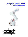
Instruction Handbook
AdeptOne-XL/
AdeptThree-XL Robot
®
Instruction Handbook
AdeptOne-XL/
AdeptThree-XL Robot
®
00862-00100, Rev. C
January 1999
®
150 Rose Orchard Way • San Jose, CA 95134 • USA • Phone (408) 432-0888 • Fax (408) 432-8707
Otto-Hahn-Strasse 23 • 44227 Dortmund • Germany • Phone (49) 231.75.89.40 • Fax (49) 231.75.89.450
adept
technology, inc.
41, rue du Saule Trapu • 91300 • Massy • France • Phone (33) 1.69.19.16.16 • Fax (33) 1.69.32.04.62
The information contained herein is the property of Adept Technology, Inc., and shall not
be reproduced in whole or in part without prior written approval of Adept Technology,
Inc. The information herein is subject to change without notice and should not be construed as a commitment by Adept Technology, Inc. This manual is periodically reviewed
and revised.
Adept Technology, Inc., assumes no responsibility for any errors or omissions in this document. Critical evaluation of this manual by the user is welcomed. Your comments assist
us in preparation of future documentation. A form is provided at the back of the book for
submitting your comments.
Copyright 1999 by Adept Technology, Inc. All rights reserved.
The Adept logo is a registered trademark of Adept Technology, Inc.
AdeptOne-XL, AdeptThree-XL, HyperDrive, Adept 550, Adept 550 CleanRoom, Adept
1850, Adept 1850XP, Adept Cobra 600, Adept Cobra 800, Adept Flexfeeder 250, Adept
MV, Adept MV4, AdeptVision, AIM, VisionWare, AdeptMotion, MotionWare,
PalletWare, FlexFeedWare, AdeptNet, AdeptFTP, AdeptNFS,
AdeptTCP/IP, AdeptForce, AdeptModules, AdeptWindows, AdeptWindows PC,
AdeptWindows DDE, AdeptWindows Offline Editor, and V+ are trademarks of
Adept Technology, Inc.
Any trademarks from other companies used in this publication
are the property of those respective companies.
Printed in the United States of America
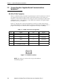
Manufacturer’s Declaration
We/Wir/Nous, Adept Technology, Inc., 150 Rose Orchard Way, San Jose, California 95134, USA, in accordance with EU
Directive 89/392/EEC, Annex II.B, declare under our sole responsibility that the product / erklären in alleiniger Verantwortung,
daß das Produkt / déclarons sous notre seule responsabilité que le produit:
Robot/Roboter:
Pendant/Handbediengerät/
Unità portatile:
Control system /
Steuerung/
Système de commande/
Sistema di comando:
EN 954:
AdeptThree-XL
AdeptOne-XL
MCP III
Category/Klasse/Catégorie 1
30862-10300
30862-10301, -10304
90332-48050
Category/Klasse/Catégorie 3
30862-10300
30862-10301, -10304
90332-48050
Adept MV-10
30340-20000, -40000
30340-20000, -40000
Adept PA-4
A Amp
Dual B+ Amp
CIP
MMSP
30336-31000
10337-15200
10338-51000
30350-10350
—
30336-31000
10337-15200
90338-51010
30350-10350
90862-00700
to which this declaration relates is in conformity with the following standards. / auf das sich diese Erklärung bezieht, mit den
folgenden Normen. / auquel se réfère cette déclaration est conforme aux normes.
We declare that the machine in the form delivered by us, subject to the usage conditions specified below, complies with the
relevant and fundamental safety and health requirements defined in EU Directive 89/392/EEC, Annex I, and the following
standards. The machine must not be put into operation until all of the machinery into which it is incorporated has been declared
in compliance with the provisions of the effective versions of the directives. This includes all supplementary equipment and
protective devices.
EU/EEA:
EN 55011:1991, Class A
EN 50082-2: 1995
EN 292-1: 1991 & EN292-2 +A1: 1995
EN 60204-1: 1997, IP20
EN 775: 1992
EN 954-1:1996
EN 1050: 1996
(EMC: Emissions)
(EMC: Immunity)
(Safety of machinery)
(Electrical safety)
(Robot safety)
(Safety related parts of control systems)
(Risk assessment)
IEC/ISO:
CISPR 11: 1990
—
—
IEC 204-1: 1992
ISO 10218:1992
—
—
EU Directives / EG-Richtlinien / Directives Communautaire / Direttiva CE:
89/392, 91/368, 93/44, 93/68 (Machinery)
89/336, 92/31, 93/68 (EMC)
73/23, 93/68 (Electrical Equipment)
Usage and installation conditions
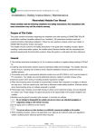
The product must be installed and used strictly in accordance with the AdeptOne/AdeptThree-XL Robot Instruction Handbook
(document p/n 00862-00100). In particular, the robot system must be installed with user-supplied perimeter barrier interlocks.
The design of the barrier interlocks must provide a Category 3 level of control per EN 954.
If the system has the EN 954 Category 1 Control System option : The barrier interlocks must interrupt the AC supply to the PA-4
Power Chassis in the event of personnel attempting to enter the workcell. You must teach the robot from outside the barrier, or
with arm power off.
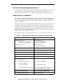
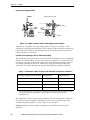
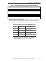
The system must incorporate only those plug-in modules and accessories listed in Table 1 or Table 2. If modules or accessories
listed in Table 2 are installed, the user must verify conformance to the EMC Directive after installation.
This Declaration applies only to those Adept product part numbers specifically listed in this declaration. The following changes
may result in the system not complying with the applicable Directives, and would void this declaration unless additional testing
and/or evaluation is performed by the user:
•
unauthorized user modifications;
•
substitution or addition of Adept parts not listed on this declaration;
•
addition of user-supplied parts and accessories.
23 November 1998
Richard J. Casler, Jr. (Vice President, Engineering)
San Jose, California, USA
AdeptOne-XL/AdeptThree-XL Robot Instruction Handbook, Rev. C
5
DEUTSCH: Hiermit erklären wir, daß die nachstehende Maschine in der von uns
gelieferten Ausführung, den einschlägigen, grundlegenden Sicherheits- und
Gesundheitsanforderungen der EG-Richtlinie 89/392/EWG Anhang I, und den unten
aufgefuehrten Standarts entspricht. Dies gilt nur wenn das Geraet unter den unten
genannten Bedingungen verwendet wird. Wir weisen daraufhin, daß die Inbetriebnahme
der Maschine solange untersagt ist, bis festgestellt ist, daß die Maschine, in die diese
Maschine eingebaut werden soll, den Bestimmungen der Richtlinie in der jeweils
gueltigen Fassung entspricht. Dies schließt die anwenderseitig in die Maschine zu
installierenden Ergänzungen und Schutzeinrichtungen ein.
FRANÇAIS: Par la présente, nous déclarons que la machine décrite ci-dessous, livrée en
l'état, est conforme à la directive communautaire 89/392/CEE, Annexe I, sur les
impératifs fondamentaux en matière de santé et de sécurité. La machine ne pourra être
mise en service avant que la machine dans laquelle elle sera incorporée ne soit déclarée
complètement conforme aux dispositions des directives en cours de validité. Ceci
comprend tout équipement complémentaire et dispositif de protection.
ITALIANO: Si dichiara che la macchina, come da noi fornita, soddisfa i requisiti
fondamentali definiti nella direttiva CE 89/392/EEC, Appendice I, in fatto di sicurezza e
sanità. La messa in funzione della macchina resta vietata fintanto che l'intero sistema nel
quale questa è incorporata sia stato dichiarato conforme alla versione vigente della
suddetta normativa. Il sistemasi intende comprensivo di tutte le parti accessorie e
dispositivi di sicurezza.
Conditions d'utilisation et d'installations
L'équipement doit être installé et utilisé en respectant scrupuleusement les instructions du
manuel «Manuel d'utilisation du robot AdeptOne/AdeptThree-XL». En particulier, les
barrières de sécurité doivent être conçues et installées pour fournir un niveau de sécurité
de catégorie 3 conforme à la norme EN 954.
Si la système fournis par Adept confèrent, selon la norme EN954, un niveau de sécurité de
catégorie 1: L'ensemble robotisé doit comporter une enceinte de sécurité, non fournie par
Adept, sectionnant l'alimentation 380V du châssis d'alimentation des variateurs (PA-4)
lors de l'intrusion d'une personne alors que le robot est asservi. L'apprentissage des
positions doit se faire de l'extérieur de cette enceinte de sécurité ou lorsque le robot est
hors asservissement.
L'ensemble ne doit comporter que les cartes enfichables ou accessoires listés dans les
tableaux 1 ou 2. Si des accessoires listés dans le tableau 2 sont installés, l'utilisateur devra,
après installation, vérifier la conformité avec les directives EMC.
Cette déclaration ne s'applique que sur les produits Adept dont les numéros de référence
sont spécifiquement listés dans cette déclaration. Les modifications suivantes sont
susceptibles d'annuler la conformité des équipements avec les directives de sécurité a
moins que de nouveaux tests ne soient effectués
•
Modifications non autorisées des équipements,
•
Substitution ou ajout de composants non listés dans cette déclaration,
•
Ajout de composants ou accessoires par le client.
6
AdeptOne-XL/AdeptThree-XL Robot Instruction Handbook, Rev. C
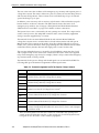
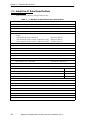
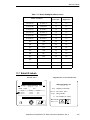
Plug-in Modules and Accessories / Einschubmodule und Zubehör /
Modules enfichables et accessoires
Table 1: Table/Tabelle/Tableau 1
Table/Tabelle/Tableau 1
Description / Beschreibung
VME Digital I/O Board /
Digitales Ein-/Ausgabemodul /
Carte d'entrées/sorties VME
VME Graphics Board / Graphik
Modul / Carte graphique VME
VME Joint Interface Board /
Achssteuerkarte / Carte d'axe
VME Motion Interface Board /
Achssteuerkarte / Carte
d'interface Mouvement VME
AWC Processor Board /
AWC Prozessormodul /
Carte processeur AWC
VME Vision Board /Vision modul /
Module d'interface vision VME
Camera / Kamera / Caméra
Optional AUX SIO Board /
AUX SIO Modul /
Module AUX SIO
Name / Namen
/ Nom
DIO
Part Number / Teilenummer /
Référence
10332-00800
Revision / Révision
VGB
10332-10250
>= P3
EJI
10332-00505
>= A
MI3
MI6
10332-11400
10332-12400
>= P4
>= P2
AWC 040
AWC 060
10332-00714
10332-00716
>= P1
>= P1
VIS
EVI
10332-00600
10332-00655
15600-00090
30332-12350
30332-12351
30332-22350
30332-22351
>= P2
>= P1
>= A
>= P2
>= P2
>= A
>= A
—
SIO
SIO
SIO/IDE
SIO/IDE
>= P2
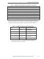
Table 2: Table/Tabelle/Tableau 2
Table/Tabelle/Tableau 2
Description / Beschreibung
Ethernet kit / Ethernet Ausrüstung /
Ethernet kit
VME Analog I/O Module / Analog
Ein-Ausgabemodul / Carte
d'entrées-sorties analogiques VME
Force-sensing kit / VFI Ausrüstung
Capteur d'efforts
MP6 Kit / MP6 Ausrüstung /
Kit MP6
Name / Namen /
Nom
AdeptNet
Part Number / Teilenummer
/ Référence
90332-02020
Revision / Révision
AIO
10330-00970
>= B
VFI
90211-00000, -08464, -00550
>= B
MP6
90332-12400
>= A
>= P1
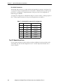
NOTE: Products listed in Table 2 must be tested by the user in the final
system configuration to assure full compliance with the European EMC
Directive.
NOTE: Les produits listés dans le tableau 2 doivent êtres testés par
l'utilisateur après l'assemblage et la configuration finale des équipements
afin de s'assurer que l'ensemble réponde aux directives Européennes
EMC.
AdeptOne-XL/AdeptThree-XL Robot Instruction Handbook, Rev. C
7
Table of Contents
1
Safety . . . . . . . . . . . . . . . . . . . . . . . . . . . . . . . . . . . . . . . . . . . . . . . . . . . . 25
Definition of a Manipulating Industrial Robot . . . . . . . . . . . . . . . . . . . . . . . 27
Adept Equipment Compatibility . . . . . . . . . . . . . . . . . . . . . . . . . . . . . . . . . . 27
1.1 Notes, Cautions, and Warnings . . . . . . . . . . . . . . . . . . . . . . . . . . . . . . . . . . . . . . 28
1.2 Precautions and Required Safeguards . . . . . . . . . . . . . . . . . . . . . . . . . . . . . . . 28
Maximum Robot Forces and Torques . . . . . . . . . . . . . . . . . . . . . . . . . . . . . .
Safety Barriers . . . . . . . . . . . . . . . . . . . . . . . . . . . . . . . . . . . . . . . . . . . . . . . . .
Impact and Trapping Points . . . . . . . . . . . . . . . . . . . . . . . . . . . . . . .
Hazards From Expelling a Part or Attached Tooling . . . . . . . . . . . .
Additional Safety Information . . . . . . . . . . . . . . . . . . . . . . . . . . . . . .
29
29
30
30
31
1.3 Risk Assessment. . . . . . . . . . . . . . . . . . . . . . . . . . . . . . . . . . . . . . . . . . . . . . . . . . . 33
1.4 Risk Assessment – Category 1 . . . . . . . . . . . . . . . . . . . . . . . . . . . . . . . . . . . . . . . 34
Installations Not Requiring Programmer to Enter Workcell . . . . . . . . . . . . . 34
Installations Requiring Programmer to Enter Workcell . . . . . . . . . . . . . . . . . 35
1.5 Intended Use of the Robots . . . . . . . . . . . . . . . . . . . . . . . . . . . . . . . . . . . . . . . . . 35
1.6 Robot Modifications . . . . . . . . . . . . . . . . . . . . . . . . . . . . . . . . . . . . . . . . . . . . . . . 37
Acceptable Modifications . . . . . . . . . . . . . . . . . . . . . . . . . . . . . . . . . . . . . . . 37
Unacceptable Modifications . . . . . . . . . . . . . . . . . . . . . . . . . . . . . . . . . . . . 37
1.7 Transport. . . . . . . . . . . . . . . . . . . . . . . . . . . . . . . . . . . . . . . . . . . . . . . . . . . . . . . . . 37
1.8 Safety Requirements for Additional Equipment . . . . . . . . . . . . . . . . . . . . . . . . . 38
1.9 Sound Emissions . . . . . . . . . . . . . . . . . . . . . . . . . . . . . . . . . . . . . . . . . . . . . . . . . . 38
1.10 Thermal Hazard . . . . . . . . . . . . . . . . . . . . . . . . . . . . . . . . . . . . . . . . . . . . . . . . . . 38
1.11 Working Areas . . . . . . . . . . . . . . . . . . . . . . . . . . . . . . . . . . . . . . . . . . . . . . . . . . 38
1.12 Qualification of Personnel . . . . . . . . . . . . . . . . . . . . . . . . . . . . . . . . . . . . . . . . . 39
1.13 Safety Equipment for Operators . . . . . . . . . . . . . . . . . . . . . . . . . . . . . . . . . . . . 40
1.14 Protection Against Unauthorized Operation. . . . . . . . . . . . . . . . . . . . . . . . . . . 40
1.15 Safety Aspects While Performing Maintenance . . . . . . . . . . . . . . . . . . . . . . . 40
1.16 Risks That Cannot Be Avoided . . . . . . . . . . . . . . . . . . . . . . . . . . . . . . . . . . . . . . 40
For Systems with MMSP Option . . . . . . . . . . . . . . . . . . . . . . . . . . . . . 40
For Systems Without MMSP Option . . . . . . . . . . . . . . . . . . . . . . . . . . 41
1.17 What to Do in an Emergency Situation . . . . . . . . . . . . . . . . . . . . . . . . . . . . . . . 41
1.18 How Can I Get Help? . . . . . . . . . . . . . . . . . . . . . . . . . . . . . . . . . . . . . . . . . . . . . 41
1.19 Related Manuals . . . . . . . . . . . . . . . . . . . . . . . . . . . . . . . . . . . . . . . . . . . . . . . . . 42
AdeptOne-XL/AdeptThree-XL Robot Instruction Handbook, Rev. C
9
Table of Contents
2
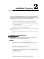
Installation Overview . . . . . . . . . . . . . . . . . . . . . . . . . . . . . . . . . . . . . . . . 43
2.1 Hardware to Be Provided by User . . . . . . . . . . . . . . . . . . . . . . . . . . . . . . . . . . . . 43
All Systems . . . . . . . . . . . . . . . . . . . . . . . . . . . . . . . . . . . . . . . . . . . . . . . . . . . . . 43
Systems Without MMSP Option . . . . . . . . . . . . . . . . . . . . . . . . . . . . . . . . . . . . 44
Systems With MMSP Option . . . . . . . . . . . . . . . . . . . . . . . . . . . . . . . . . . . . . . . 44
2.2 Facility Requirements . . . . . . . . . . . . . . . . . . . . . . . . . . . . . . . . . . . . . . . . . . . . . . 44
Compressed Air Requirements . . . . . . . . . . . . . . . . . . . . . . . . . . . . . . . . . . . . 44
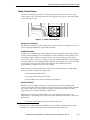
Mounting Surface Specifications. . . . . . . . . . . . . . . . . . . . . . . . . . . . . . . . . . . 45
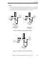
Plate. . . . . . . . . . . . . . . . . . . . . . . . . . . . . . . . . . . . . . . . . . . . . . . . . . . . 45
Spool . . . . . . . . . . . . . . . . . . . . . . . . . . . . . . . . . . . . . . . . . . . . . . . . . . . 45
2.3 Environmental Requirements . . . . . . . . . . . . . . . . . . . . . . . . . . . . . . . . . . . . . . . . 47
2.4 Power Requirements . . . . . . . . . . . . . . . . . . . . . . . . . . . . . . . . . . . . . . . . . . . . . . . 48
Adept MV Controller Power Requirements . . . . . . . . . . . . . . . . . . . . . . . . . . 48
Facility Overvoltage Protection . . . . . . . . . . . . . . . . . . . . . . . . . . . . . 48
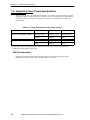
PA-4 Power Chassis Power Requirements . . . . . . . . . . . . . . . . . . . . . . . . . . . . 49
2.5 Before Unpacking the Adept Equipment. . . . . . . . . . . . . . . . . . . . . . . . . . . . . . . 49
2.6 Adept Shipment Specifications . . . . . . . . . . . . . . . . . . . . . . . . . . . . . . . . . . . . . . 49
2.7 Transport and Storage . . . . . . . . . . . . . . . . . . . . . . . . . . . . . . . . . . . . . . . . . . . . . . 50
Shipping and Storage. . . . . . . . . . . . . . . . . . . . . . . . . . . . . . . . . . . . . . . . . . . . 50
2.8 Lifting and Handling . . . . . . . . . . . . . . . . . . . . . . . . . . . . . . . . . . . . . . . . . . . . . . . . 50
Before Unpacking . . . . . . . . . . . . . . . . . . . . . . . . . . . . . . . . . . . . . . . . . . . . . . . 50
2.9 Unpacking and Inspecting the Adept Equipment . . . . . . . . . . . . . . . . . . . . . . . 51
Upon Unpacking . . . . . . . . . . . . . . . . . . . . . . . . . . . . . . . . . . . . . . . . . . . . . . . . 51
2.10 Repacking for Relocation . . . . . . . . . . . . . . . . . . . . . . . . . . . . . . . . . . . . . . . . . . 52
2.11 Robot and Controller ID Labels. . . . . . . . . . . . . . . . . . . . . . . . . . . . . . . . . . . . . . 52
3
Robot Installation . . . . . . . . . . . . . . . . . . . . . . . . . . . . . . . . . . . . . . . . . . . 53
3.1 Mounting the Robot . . . . . . . . . . . . . . . . . . . . . . . . . . . . . . . . . . . . . . . . . . . . . . . . 53
Tool and Equipment Requirements. . . . . . . . . . . . . . . . . . . . . . . . . . . . . . . . . 53
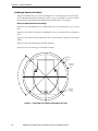
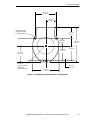
Installing a Base for the Robot . . . . . . . . . . . . . . . . . . . . . . . . . . . . . . . . . . . . . 54
Robot Installation Dimension Drawings . . . . . . . . . . . . . . . . . . . . . . . 54
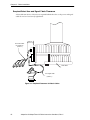
Required Robot Arm and Signal Cable Clearance . . . . . . . . . . . . . . . . . . . 56
Installing a Mounting Plate . . . . . . . . . . . . . . . . . . . . . . . . . . . . . . . . . 58
Installing a Mounting Spool. . . . . . . . . . . . . . . . . . . . . . . . . . . . . . . . . 59
Mounting a Robot on a Base . . . . . . . . . . . . . . . . . . . . . . . . . . . . . . . . . . . . . 60
3.2 Using the Brake Release Button . . . . . . . . . . . . . . . . . . . . . . . . . . . . . . . . . . . . . . 62
Brakes . . . . . . . . . . . . . . . . . . . . . . . . . . . . . . . . . . . . . . . . . . . . . . . . . . . . . . . . 62
Brake Release Button . . . . . . . . . . . . . . . . . . . . . . . . . . . . . . . . . . . . . . . . . . . . 62
3.3 Limiting Joint Travel . . . . . . . . . . . . . . . . . . . . . . . . . . . . . . . . . . . . . . . . . . . . . . . . 62
Softstops . . . . . . . . . . . . . . . . . . . . . . . . . . . . . . . . . . . . . . . . . . . . . . . . . . . . . . . 62
10
AdeptOne-XL/AdeptThree-XL Robot Instruction Handbook, Rev. C
Table of Contents
Hardstops . . . . . . . . . . . . . . . . . . . . . . . . . . . . . . . . . . . . . . . . . . . . . . . . . . . . . 62
Cartesian Limit Stops . . . . . . . . . . . . . . . . . . . . . . . . . . . . . . . . . . . . . . . . . . . . 63
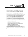
4
Adept MV Controller Installation . . . . . . . . . . . . . . . . . . . . . . . . . . . . . . 65
AdeptWindows Controller (AWC) Board Connectors and Indicators . . . .
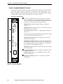
A Amplifier Module Overview. . . . . . . . . . . . . . . . . . . . . . . . . . . . . . . . . . . . .
Connectors and Indicators . . . . . . . . . . . . . . . . . . . . . . . . . . . . . . . .
Dual B+ Amplifier Module Overview . . . . . . . . . . . . . . . . . . . . . . . . . . . . . . .
Connectors and Indicators . . . . . . . . . . . . . . . . . . . . . . . . . . . . . . . .
66
67
67
68
68
4.1 Mounting the Adept MV Controller and Power Chassis . . . . . . . . . . . . . . . . . . 69
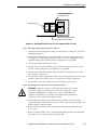
Joining an Adept PA-4 Power Chassis to an Adept MV Controller . . . . . .
Joining at the Top . . . . . . . . . . . . . . . . . . . . . . . . . . . . . . . . . . . . . . . .
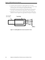
Joining at the Bottom . . . . . . . . . . . . . . . . . . . . . . . . . . . . . . . . . . . . .
Space Around the Chassis . . . . . . . . . . . . . . . . . . . . . . . . . . . . . . . . . . . . . . .
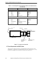
Rack or Panel Mounting . . . . . . . . . . . . . . . . . . . . . . . . . . . . . . . . . . . . . . . . .
Panel Mounting . . . . . . . . . . . . . . . . . . . . . . . . . . . . . . . . . . . . . . . . .
Rack Mounting . . . . . . . . . . . . . . . . . . . . . . . . . . . . . . . . . . . . . . . . . .
69
70
71
71
71
72
72
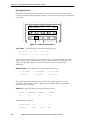
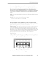
4.2 Controller Interface Panel Description . . . . . . . . . . . . . . . . . . . . . . . . . . . . . . . . 75
Panel Switches and Indicators . . . . . . . . . . . . . . . . . . . . . . . . . . . . . . . . . . . .
Emergency Stop Switch . . . . . . . . . . . . . . . . . . . . . . . . . . . . . . . . . . .
Manual/Automatic Mode Switch . . . . . . . . . . . . . . . . . . . . . . . . . . .
High Power Enabling Switch/Lamp. . . . . . . . . . . . . . . . . . . . . . . . . .
Manual Control Pendant (MCP) Connector . . . . . . . . . . . . . . . . . .
System Power Switch . . . . . . . . . . . . . . . . . . . . . . . . . . . . . . . . . . . . .
NET Switch . . . . . . . . . . . . . . . . . . . . . . . . . . . . . . . . . . . . . . . . . . . . . .
Side Connectors. . . . . . . . . . . . . . . . . . . . . . . . . . . . . . . . . . . . . . . . . . . . . . . .
AWC Interface (JAWC) . . . . . . . . . . . . . . . . . . . . . . . . . . . . . . . . . . .
User Connector (JUSER) . . . . . . . . . . . . . . . . . . . . . . . . . . . . . . . . . . .
Back Panel Connectors. . . . . . . . . . . . . . . . . . . . . . . . . . . . . . . . . . . . . . . . . .
RS-232 (JCOM) . . . . . . . . . . . . . . . . . . . . . . . . . . . . . . . . . . . . . . . . . .
Manual Mode Safety Package (MMSP) . . . . . . . . . . . . . . . . . . . . .
AUX (JEXT) . . . . . . . . . . . . . . . . . . . . . . . . . . . . . . . . . . . . . . . . . . . . . .
CIB (JSLV) . . . . . . . . . . . . . . . . . . . . . . . . . . . . . . . . . . . . . . . . . . . . . . .
DeviceNet (JDVC) . . . . . . . . . . . . . . . . . . . . . . . . . . . . . . . . . . . . . . .
Digital I/O Connections . . . . . . . . . . . . . . . . . . . . . . . . . . . . . . . . . . .
75
75
75
76
76
76
76
76
76
76
77
77
77
77
77
77
78
4.3 Mounting the Controller Interface Panel (CIP) . . . . . . . . . . . . . . . . . . . . . . . . . . 79
Location of the CIP . . . . . . . . . . . . . . . . . . . . . . . . . . . . . . . . . . . . . . . . . . . . . 79
4.4 Connecting the CIP to the AWC . . . . . . . . . . . . . . . . . . . . . . . . . . . . . . . . . . . . . 79
Extended Length CIP-to-AWC Cable . . . . . . . . . . . . . . . . . . . . . . . . . . . . . . 80
4.5 Connecting the MCP to the CIP. . . . . . . . . . . . . . . . . . . . . . . . . . . . . . . . . . . . . . 80
MCP Cradle . . . . . . . . . . . . . . . . . . . . . . . . . . . . . . . . . . . . . . . . . . . . . . . . . . . 81
MCP Bypass Plug . . . . . . . . . . . . . . . . . . . . . . . . . . . . . . . . . . . . . . . . . . . . . . . 81
4.6 Robot and Control System Cable Installation . . . . . . . . . . . . . . . . . . . . . . . . . . 82
System Cable Lengths . . . . . . . . . . . . . . . . . . . . . . . . . . . . . . . . . . . . . . . . . . . 83
AdeptOne-XL/AdeptThree-XL Robot Instruction Handbook, Rev. C
11
Table of Contents
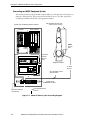
Connecting the Robot to the Power Chassis. . . . . . . . . . . . . . . . . . . . . . . . . 83
Connecting the Robot to the MV Controller . . . . . . . . . . . . . . . . . . . . . . . . . 85
Connecting the Adept MV Controller to the Power Chassis . . . . . . . . . . . . 86
4.7 Connecting AC Power to the Adept MV Controllers . . . . . . . . . . . . . . . . . . . . . 87
Power Entry Board . . . . . . . . . . . . . . . . . . . . . . . . . . . . . . . . . . . . . . . . . . . . . . . 87
Connecting AC Power Cord . . . . . . . . . . . . . . . . . . . . . . . . . . . . . . . . . . . . . . 87
System Grounding Information . . . . . . . . . . . . . . . . . . . . . . . . . . . . . . . . . . . . 88
4.8 Manual Mode Safety Package Installation . . . . . . . . . . . . . . . . . . . . . . . . . . . . . 88
4.9 Changing the Power Chassis Voltage Setting. . . . . . . . . . . . . . . . . . . . . . . . . . . 89
Changing From 380-415 VAC to 200-240 VAC . . . . . . . . . . . . . . . . . . . . . . . . 89
Changing From 200-240 VAC to 380-415 VAC . . . . . . . . . . . . . . . . . . . . . . . . 90
4.10 Connecting AC Power to the Adept PA-4 Power Chassis . . . . . . . . . . . . . . . . 92
Connecting the Power Chassis AC Power Cord to AC Supply
(Non-MMSP System) . . . . . . . . . . . . . . . . . . . . . . . . . . . . . . . . . . . . . . . . . . . 92
4.11 Grounding the Adept Robot System . . . . . . . . . . . . . . . . . . . . . . . . . . . . . . . . . 93
Adept Robot Grounding . . . . . . . . . . . . . . . . . . . . . . . . . . . . . . . . . . . . . . . . . 93
Robot-Mounted Equipment Grounding . . . . . . . . . . . . . . . . . . . . . . . . . . . . . 94
5
MMSP Installation and Configuration . . . . . . . . . . . . . . . . . . . . . . . . . . . 95
5.1 Installation of the MMSP Option . . . . . . . . . . . . . . . . . . . . . . . . . . . . . . . . . . . . . . 95
Connecting the Security Panel to the CIP . . . . . . . . . . . . . . . . . . . . . . . . . . . 97
Connecting the Security Panel to the Adept Robot . . . . . . . . . . . . . . . . . . 98
Connecting the Security Panel to the Adept PA-4 Power Chassis . . . . . . . 98
Changing the Voltage Setting for the Power Chassis
(From 380-415 VAC to 200-240 VAC) . . . . . . . . . . . . . . . . . . . . . . . . . . . . . . 99
Changing the Voltage Setting for the Power Chassis
(From 200-240VAC to 380-415VAC) . . . . . . . . . . . . . . . . . . . . . . . . . . . . . . 102
Connecting AC Power to the Adept PA-4 Power Chassis . . . . . . . . . . . . . 105
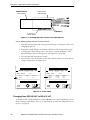
Typical AC Power Installation Diagrams . . . . . . . . . . . . . . . . . . . . . 106
Connecting Power Cord of Power Chassis to Security Panel. . . . 107
AC Power Requirements for MMSP Option . . . . . . . . . . . . . . . . . . . . . . . . . 108
Connecting AC Power to the Security Panel. . . . . . . . . . . . . . . . . . . . . . . . 109
Grounding an MMSP Equipped System . . . . . . . . . . . . . . . . . . . . . . . . . . . . 110
5.2 Security Panel Functions . . . . . . . . . . . . . . . . . . . . . . . . . . . . . . . . . . . . . . . . . . . 111
Description of “Mute” Capability . . . . . . . . . . . . . . . . . . . . . . . . . . . . . . . . . 111
Operating in Manual Mode . . . . . . . . . . . . . . . . . . . . . . . . . . . . . . . . . . . . . 112
5.3 Category 3 Emergency Stop and Teach Restrict Equipment . . . . . . . . . . . . . 113
Terminal Assignments for Customer E-Stops . . . . . . . . . . . . . . . . . . . . . . . . . 114
Voltage-Free Contacts for Monitoring E-Stop Circuitry (Passive E-Stop) . 115
5.4 Category 3 Emergency Stop Circuitry . . . . . . . . . . . . . . . . . . . . . . . . . . . . . . . . 117
5.5 Digital Signals on the Category 3 E-Stop Board . . . . . . . . . . . . . . . . . . . . . . . . 121
Input Signals . . . . . . . . . . . . . . . . . . . . . . . . . . . . . . . . . . . . . . . . . . . . 121
12
AdeptOne-XL/AdeptThree-XL Robot Instruction Handbook, Rev. C
Table of Contents
Output Signals . . . . . . . . . . . . . . . . . . . . . . . . . . . . . . . . . . . . . . . . . . 122
6
User Interface Installation . . . . . . . . . . . . . . . . . . . . . . . . . . . . . . . . . . . 125
6.1 Graphical User Interface Using the VGB Board . . . . . . . . . . . . . . . . . . . . . . . . 126
Installation Procedure . . . . . . . . . . . . . . . . . . . . . . . . . . . . . . . . . . . . . . . . . . 126
6.2 Text-Based Interface Using a Terminal . . . . . . . . . . . . . . . . . . . . . . . . . . . . . . . 128
Recommended Terminal for Text-Based Systems. . . . . . . . . . . . . . . . . . . . 128
Installation Procedure . . . . . . . . . . . . . . . . . . . . . . . . . . . . . . . . . . . . . . . . . . 128
6.3 Graphical Interface Using AdeptWindows PC . . . . . . . . . . . . . . . . . . . . . . . . . 129
Installing the AdeptWindows Software . . . . . . . . . . . . . . . . . . . . . . . . . . . . 129
Setting Up the TCP/IP Interface (Ethernet Connection) . . . . . . . . . . . . . . 130
Connecting One PC and One Controller . . . . . . . . . . . . . . . . . . . . . . . . . . 134
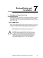
7
Optional Equipment Installation . . . . . . . . . . . . . . . . . . . . . . . . . . . . . . 137
7.1 User Signal and Solenoid Driver Lines . . . . . . . . . . . . . . . . . . . . . . . . . . . . . . . . 137
USER1-1 Through USER 2-4 . . . . . . . . . . . . . . . . . . . . . . . . . . . . . . . . . . . . . . . 137
7.2 Adept-XL Joint 5 Wiring . . . . . . . . . . . . . . . . . . . . . . . . . . . . . . . . . . . . . . . . . . . 141
7.3 Adept-XL Robot Solenoid Kit . . . . . . . . . . . . . . . . . . . . . . . . . . . . . . . . . . . . . . . 141
Tools Required. . . . . . . . . . . . . . . . . . . . . . . . . . . . . . . . . . . .
Installation Procedure . . . . . . . . . . . . . . . . . . . . . . . . . . . . .
Install the 24 Volt Valve Assembly . . . . . . . . . . . . .
Test the Gripper Valves . . . . . . . . . . . . . . . . . . . . .
Compressed Air Lines In the Adept-XL Robot. . . . . . . . . .
Gripper Solenoid Drivers . . . . . . . . . . . . . . . . . . . . . . . . . . .
.............
.............
.............
.............
.............
.............
141
141
141
147
148
148
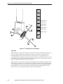
7.4 Adept-XL Robot Camera Bracket Kit . . . . . . . . . . . . . . . . . . . . . . . . . . . . . . . . 149
Introduction . . . . . . . . . . . . . . . . . . . . . . . . . . . . . . . . . . . . . . . . . . . . . . . . . .
Tools Required. . . . . . . . . . . . . . . . . . . . . . . . . . . . . . . . . . . . . . . . . . . . . . . . .
Installation Time . . . . . . . . . . . . . . . . . . . . . . . . . . . . . . . . . . . . . . . . . . . . . . .
Procedure . . . . . . . . . . . . . . . . . . . . . . . . . . . . . . . . . . . . . . . . . . . . . . . . . . . .
149
149
149
149
7.5 Mounting User Equipment on the Robot Arm . . . . . . . . . . . . . . . . . . . . . . . . . . 151
7.6 Installing End-Effectors on an Adept-XL Robot . . . . . . . . . . . . . . . . . . . . . . . . 153
Calculating Payload Inertia . . . . . . . . . . . . . . . . . . . . . . . . . . . . . . . . . . . . . 153
Adept-XL Initial Payload and GAIN.SET Tuning Values for Joint 4 . . . . . . . 154
7.7 DeviceNet Communication Link . . . . . . . . . . . . . . . . . . . . . . . . . . . . . . . . . . . . 156
Recommended Vendors for Mating Cables and Connectors. . . . . . . . . 156
7.8 Ethernet Connections . . . . . . . . . . . . . . . . . . . . . . . . . . . . . . . . . . . . . . . . . . . . . 157
7.9 Connecting User Supplied Serial Communications Equipment . . . . . . . . . . . 158
RS-232 (JCOM) Connector . . . . . . . . . . . . . . . . . . . . . . . . . . . . . . . . . . . . . .
AdeptWindows Controller (AWC) Board Serial I/O Ports . . . . . . .
Serial Port 2 (RS-232) . . . . . . . . . . . . . . . . . . . . . . . . . . . . . . . . . . . . .
RS-422/485 Connector . . . . . . . . . . . . . . . . . . . . . . . . . . . . . . . . . . .
AdeptOne-XL/AdeptThree-XL Robot Instruction Handbook, Rev. C
158
159
159
160
13
Table of Contents
The SIO Board Serial Ports . . . . . . . . . . . . . . . . . . . . . . . . . . . . . . . . . . . . . . . . 160
7.10 Connecting Customer-Supplied Safety and Power Control
Equipment to the CIP . . . . . . . . . . . . . . . . . . . . . . . . . . . . . . . . . . . . . . . . . . . 161
Emergency Stop Circuit . . . . . . . . . . . . . . . . . . . . . . . . . . . . . . . . . . . . . . . . . 165
Remote Sensing of CIP, MCP, and User E-Stop Push Button
Switches . . . . . . . . . . . . . . . . . . . . . . . . . . . . . . . . . . . . . . . . . . . . . . 165
Muted Safety Gate E-Stop Circuitry. . . . . . . . . . . . . . . . . . . . . . . . . 166
JSIO E-Stop Circuitry. . . . . . . . . . . . . . . . . . . . . . . . . . . . . . . . . . . . . . 166
Category 3 E-Stop . . . . . . . . . . . . . . . . . . . . . . . . . . . . . . . . . . . . . . . 166
Remote Manual Mode Control . . . . . . . . . . . . . . . . . . . . . . . . . . . . . . . . . . . 167
Remote High Power Control . . . . . . . . . . . . . . . . . . . . . . . . . . . . . . . . . . . . . 167
Remote High Power On/Off Lamp. . . . . . . . . . . . . . . . . . . . . . . . . . 168
Connecting the System Power Switch to the CIP . . . . . . . . . . . . . . . . . . . . 169
Manual Mode Safety Package (MMSP) Connector. . . . . . . . . . . . . . . . . . 171
Remote User Panel Connections . . . . . . . . . . . . . . . . . . . . . . . . . . . . . . . . . 172
Remote MCP Connections . . . . . . . . . . . . . . . . . . . . . . . . . . . . . . . . . . . . . . 172
Remote E-Stop Circuit . . . . . . . . . . . . . . . . . . . . . . . . . . . . . . . . . . . . 172
Remote Enable Switch Connections . . . . . . . . . . . . . . . . . . . . . . . . 172
7.11 Connecting User-Supplied Digital I/O Equipment . . . . . . . . . . . . . . . . . . . . . 173
JSIO Connector . . . . . . . . . . . . . . . . . . . .
REACT Input Signals 1001 to 1012 . . . . . .
Fast Input Signals 1001 to 1004 . . . . . . . .
Output Signals . . . . . . . . . . . . . . . . . . . . .
..............
..............
..............
..............
.......
.......
.......
.......
173
174
174
175
7.12 Extended Digital I/O Signals . . . . . . . . . . . . . . . . . . . . . . . . . . . . . . . . . . . . . . . 177
8
Verifying the System Installation . . . . . . . . . . . . . . . . . . . . . . . . . . . . . . 179
8.1 Installation Check List . . . . . . . . . . . . . . . . . . . . . . . . . . . . . . . . . . . . . . . . . . . . . 179
Mechanical Checks . . . . . . . . . . . . . . . . . . . . . . . . . . . . . . . . . . . . . . . . . . . . 179
AC Power to the Adept Components Checks . . . . . . . . . . . . . . . . . . . . . . 179
Board and Cable Installation Checks . . . . . . . . . . . . . . . . . . . . . . . . . . . . . 180
Cable Connection Summary (All Systems) . . . . . . . . . . . . . . . . . . . 180
Cable Connection Summary (MMSP Systems). . . . . . . . . . . . . . . . 181
User-Supplied Safety Equipment on JUSER and JSIO Connector Checks 181
E-Stop Button and Switch Checks . . . . . . . . . . . . . . . . . . . . . . . . . . . . . . . . . 181
8.2 Applying Power to the Adept Control System. . . . . . . . . . . . . . . . . . . . . . . . . . 182
LED Status Indicators on the AWC . . . . . . . . . . . . . . . . . . . . . . . . . . 183
8.3 Checks After Applying Power. . . . . . . . . . . . . . . . . . . . . . . . . . . . . . . . . . . . . . . 183
8.4 Using the SAFE_UTL Program (MMSP Only) . . . . . . . . . . . . . . . . . . . . . . . . . . . . 184
Category 3 Robot Components . . . . . . . . . . . . . . . . . . . . . . . . . . . . . . . . . . 184
Accelerometer . . . . . . . . . . . . . . . . . . . . . . . . . . . . . . . . . . . . . . . . . . 184
B+ Amplifier Voltage Restrict . . . . . . . . . . . . . . . . . . . . . . . . . . . . . . 184
CIP Switches and Buttons . . . . . . . . . . . . . . . . . . . . . . . . . . . . . . . . . 184
MCP Enabling Switch. . . . . . . . . . . . . . . . . . . . . . . . . . . . . . . . . . . . . 184
Dual Brake Solenoid Valves . . . . . . . . . . . . . . . . . . . . . . . . . . . . . . . 185
14
AdeptOne-XL/AdeptThree-XL Robot Instruction Handbook, Rev. C
Table of Contents
Robot Brakes . . . . . . . . . . . . . . . . . . . . . . . . . . . . . . . . . . . . . . . . . . . 185
8.5 SAFE_UTL.V2 . . . . . . . . . . . . . . . . . . . . . . . . . . . . . . . . . . . . . . . . . . . . . . . . . . . . . 185
Commissioned vs. Not Commissioned . . . . . . . . . . . . . . . . . . . . . . . . . . . . 185
Starting the SAFE_UTL Utility . . . . . . . . . . . . . . . . . . . . . . . . . . . . . . . . . . . . . . 186
8.6 Tests Performed at Time of Commissioning . . . . . . . . . . . . . . . . . . . . . . . . . . . 186
Accelerometer Test . . . . . . . . . . . . . . . . . . . . . . . . . . . . . . . . . . . . . . . . . . . .
B+ Amp Voltage Restrict Test . . . . . . . . . . . . . . . . . . . . . . . . . . . . . . . . . . . .
CIP Switch and Button Test . . . . . . . . . . . . . . . . . . . . . . . . . . . . . . . . . . . . . .
MCP E-STOP Functions . . . . . . . . . . . . . . . . . . . . . . . . . . . . . . . . . . . . . . . . . .
Brake Holding Force Test . . . . . . . . . . . . . . . . . . . . . . . . . . . . . . . . . . . . . . . .
Additional MMSP Diagnostic Tests . . . . . . . . . . . . . . . . . . . . . . . . . . . . . . . .
187
189
190
191
192
193
8.7 Tests Performed Periodically . . . . . . . . . . . . . . . . . . . . . . . . . . . . . . . . . . . . . . . 193
Required Tools. . . . . . . . . . . . . . . . . . . . . . . . . . . . . . . . . . . . . . . . . . . . . . . . . 194
Testing the Dual Brake Valves (With MMSP) . . . . . . . . . . . . . . . . . . . . . . . . 194
9
Using the Manual Control Pendant (MCP) . . . . . . . . . . . . . . . . . . . . . 197
9.1 Robot Operating Modes . . . . . . . . . . . . . . . . . . . . . . . . . . . . . . . . . . . . . . . . . . . 197
Manual Operating Mode . . . . . . . . . . . . . . . . . . . . . . . . . . . . . . . . . . . . . . . 197
Automatic Operating Mode . . . . . . . . . . . . . . . . . . . . . . . . . . . . . . . . . . . . 198
9.2 Manual Control Pendant Basics. . . . . . . . . . . . . . . . . . . . . . . . . . . . . . . . . . . . . 199
Connecting the MCP . . . . . . . . . . . . . . . . . . . . . . . . . . . . . . . . . . . .
MCP Layout . . . . . . . . . . . . . . . . . . . . . . . . . . . . . . . . . . . . . . . . . . . . . . . . . .
Soft Buttons . . . . . . . . . . . . . . . . . . . . . . . . . . . . . . . . . . . . . . . . . . . .
Function Buttons . . . . . . . . . . . . . . . . . . . . . . . . . . . . . . . . . . . . . . . .
Data Entry Buttons. . . . . . . . . . . . . . . . . . . . . . . . . . . . . . . . . . . . . . .
Mode Control and Joint/Axis Control Buttons . . . . . . . . . . . . . . . .
Speed Bars and Slow Button . . . . . . . . . . . . . . . . . . . . . . . . . . . . . .
Emergency Stop From the MCP . . . . . . . . . . . . . . . . . . . . . . . . . . . . . . . . . .
Background Mode. . . . . . . . . . . . . . . . . . . . . . . . . . . . . . . . . . . . . . . . . . . . .
200
201
201
202
202
202
202
203
203
9.3 MCP Predefined Functions . . . . . . . . . . . . . . . . . . . . . . . . . . . . . . . . . . . . . . . . . 203
Introduction . . . . . . . . . . . . . . . . . . . . . . . . . . . . . . . . . . . . . . . . . . . . . . . . . .
Predefined Function Buttons. . . . . . . . . . . . . . . . . . . . . . . . . . . . . . . . . . . . .
The Edit Function . . . . . . . . . . . . . . . . . . . . . . . . . . . . . . . . . . . . . . . .
The Display Function . . . . . . . . . . . . . . . . . . . . . . . . . . . . . . . . . . . . .
The Clear Error Function . . . . . . . . . . . . . . . . . . . . . . . . . . . . . . . . . .
The CMD Function . . . . . . . . . . . . . . . . . . . . . . . . . . . . . . . . . . . . . .
Prog Set Function . . . . . . . . . . . . . . . . . . . . . . . . . . . . . . . . . . . . . . .
203
203
204
206
207
208
209
9.4 Moving a Robot or Motion Device With the MCP. . . . . . . . . . . . . . . . . . . . . . . 210
Introduction . . . . . . . . . . . . . . . . . . . . . . . . . . . . . . . . . . . . . . . . . . . . . . . . . .
Mode Control Buttons . . . . . . . . . . . . . . . . . . . . . . . . . . . . . . . . . . . . . . . . . .
Emergency Stop Button . . . . . . . . . . . . . . . . . . . . . . . . . . . . . . . . . .
COMP/PWR Button . . . . . . . . . . . . . . . . . . . . . . . . . . . . . . . . . . . . . .
MAN/HALT Button . . . . . . . . . . . . . . . . . . . . . . . . . . . . . . . . . . . . . . .
DIS PWR Button . . . . . . . . . . . . . . . . . . . . . . . . . . . . . . . . . . . . . . . . .
AdeptOne-XL/AdeptThree-XL Robot Instruction Handbook, Rev. C
210
210
211
211
211
212
15
Table of Contents
RUN/HOLD. . . . . . . . . . . . . . . . . . . . . . . . . . . . . . . . . . . . . . . . . . . . . . 212
Joint/Axis Control Buttons. . . . . . . . . . . . . . . . . . . . . . . . . . . . . . . . . . . . . . . . 212
STEP Button . . . . . . . . . . . . . . . . . . . . . . . . . . . . . . . . . . . . . . . . . . . . . 212
Speed Bars . . . . . . . . . . . . . . . . . . . . . . . . . . . . . . . . . . . . . . . . . . . . . . . . . . . . 212
In World, Tool, and Joint Mode . . . . . . . . . . . . . . . . . . . . . . . . . . . . 212
In Comp Mode . . . . . . . . . . . . . . . . . . . . . . . . . . . . . . . . . . . . . . . . . . 212
Slow Button . . . . . . . . . . . . . . . . . . . . . . . . . . . . . . . . . . . . . . . . . . . . . . . . . . . 213
Robot States . . . . . . . . . . . . . . . . . . . . . . . . . . . . . . . . . . . . . . . . . . . . . . . . . . 213
World State . . . . . . . . . . . . . . . . . . . . . . . . . . . . . . . . . . . . . . . . . . . . . 213
Tool State . . . . . . . . . . . . . . . . . . . . . . . . . . . . . . . . . . . . . . . . . . . . . . 214
Joint State . . . . . . . . . . . . . . . . . . . . . . . . . . . . . . . . . . . . . . . . . . . . . . 216
Free State . . . . . . . . . . . . . . . . . . . . . . . . . . . . . . . . . . . . . . . . . . . . . . 218
Controlling More Than One Robot . . . . . . . . . . . . . . . . . . . . . . . . . . . . . . . . 219
Robots With Fewer Than Six Joints . . . . . . . . . . . . . . . . . . . . . . . . . . 220
Robots With More Than Six Joints . . . . . . . . . . . . . . . . . . . . . . . . . . . 220
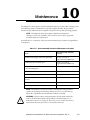
10
Maintenance . . . . . . . . . . . . . . . . . . . . . . . . . . . . . . . . . . . . . . . . . . . 221
10.1 Testing the MMSP Hardware . . . . . . . . . . . . . . . . . . . . . . . . . . . . . . . . . . . . . . . 222
10.2 Robot Lubrication . . . . . . . . . . . . . . . . . . . . . . . . . . . . . . . . . . . . . . . . . . . . . . . 222
Recommended Grease for the Adept-XL Robot . . . . . . . . . . . . .
Joint-1 Encoder Gear . . . . . . . . . . . . . . . . . . . . . . . . . . . . .
Joint-3 (Upper and Lower) Quill Shaft . . . . . . . . . . . . . . . .
Manufacturer’s Safety Data Sheets (MSDS) . . . . . . . . . . .
Lubricating Joint-1 Encoder Gear – Adept-XL Robot . . . . . . . . . .
Lubricating Joint 3 Upper Quill Shaft – Adept-XL Robot . . . . . . . .
Lubricating Joint-3 Lower Quill Shaft – Adept-XL Robot . . . . . . . .
.......
.......
.......
.......
.......
.......
.......
222
222
222
222
223
225
228
10.3 Check Robot Mounting Bolt Tightness . . . . . . . . . . . . . . . . . . . . . . . . . . . . . . 228
10.4 Maintenance and Inspection of Air Filters. . . . . . . . . . . . . . . . . . . . . . . . . . . . 228
Draining Moisture From Adept-XL Robot Compressed Air Filter . . . . . . . . 228
Adept-XL Robot Fan Filter Inspection and Cleaning . . . . . . . . . . . . . . . . . 229
Adept PA-4 Power Chassis Fan Filter Inspection and Cleaning . . . . . . . . . 229
Adept MV Controller Fan Filter Inspection and Cleaning . . . . . . . . . . . . . 229
10.5 Changing the Lamp on the CIP High Power Enable Switch . . . . . . . . . . . . . . 230
10.6 Controller Fuse Information . . . . . . . . . . . . . . . . . . . . . . . . . . . . . . . . . . . . . . . 233
10.7 Special Maintenance for Adept-XL IP 54 Robot . . . . . . . . . . . . . . . . . . . . . . . 234
Rotary Seal Assemblies . . . . . . . . . . . . . . . . . . . . . . . . . . . . . . . . . . . 234
Fixed Seals. . . . . . . . . . . . . . . . . . . . . . . . . . . . . . . . . . . . . . . . . . . . . . 234
Cleaning Information . . . . . . . . . . . . . . . . . . . . . . . . . . . . . . . . . . . . . . . . . . . 234
Removing the End-Effector for Cleaning . . . . . . . . . . . . . . . . . . . . 234
Cleaning Procedure . . . . . . . . . . . . . . . . . . . . . . . . . . . . . . . . . . . . . 234
Drying Time Before Operation . . . . . . . . . . . . . . . . . . . . . . . . . . . . . 235
Bolt Removal /Resealing Procedure – Adept-XL IP 54 Robot. . . . . . . . . . . 235
10.8 Adept-XL Clean Room Robot Bellows Replacement . . . . . . . . . . . . . . . . . . 236
Required Materials and Tools. . . . . . . . . . . . . . . . . . . . . . . . . . . . . . . . . . . . . 236
16
AdeptOne-XL/AdeptThree-XL Robot Instruction Handbook, Rev. C
Table of Contents
Removing the Bellows . . . . . . . . . . . . . . . . . . . . . . . . . . . . . . . . . . . . . . . . . . 236
Installing the New Bellows . . . . . . . . . . . . . . . . . . . . . . . . . . . . . . . . . . . . . . . 236
Further Instructions . . . . . . . . . . . . . . . . . . . . . . . . . . . . . . . . . . . . . . . . . . . . . 237
10.9 PA-4 Power Chassis Circuit Breaker and Fuse Information . . . . . . . . . . . . . . 238
Chassis Circuit Breaker. . . . . . . . . . . . . . . . . . . . . . . . . . . . . . . . . . . . . . . . . .
Chassis and Amplifier Module Fuses . . . . . . . . . . . . . . . . . . . . . . . . . . . . . .
Removing and Installing Amplifier Modules . . . . . . . . . . . . . . . . . . . . . . . .
Removing Amplifier Modules . . . . . . . . . . . . . . . . . . . . . . . . . . . . .
Installing Amplifier Modules . . . . . . . . . . . . . . . . . . . . . . . . . . . . . . .
238
238
238
239
239
10.10 Spare Parts List: MV-5/MV-10 . . . . . . . . . . . . . . . . . . . . . . . . . . . . . . . . . . . . . 240
10.11 Spare Parts List: PA-4 Amplifier Chassis. . . . . . . . . . . . . . . . . . . . . . . . . . . . . 241
10.12 Spare Parts List: Adept-XL Robot . . . . . . . . . . . . . . . . . . . . . . . . . . . . . . . . . . 241
11
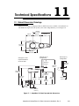
Technical Specifications . . . . . . . . . . . . . . . . . . . . . . . . . . . . . . . . . . 243
11.1 Robot Dimension Drawings . . . . . . . . . . . . . . . . . . . . . . . . . . . . . . . . . . . . . . . 243
.............................................................
Customer External Equipment Mounting Area. . . . . . . . . . . . . . . . . . . . . .
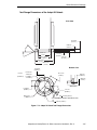
Dimensions of the Camera Bracket Mounting Pattern . . . . . . . . . . . . . . .
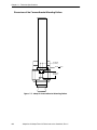
Tool Flange Dimensions of the Adept-XL Robots . . . . . . . . . . . . . . . . . . . .
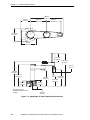
Dimensions of the Adept MV-10 and Adept MV-5 Controllers . . . . . . . . .
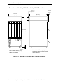
Dimensions of the Adept PA-4 Power Chassis . . . . . . . . . . . . . . . . . . . . . . .
Dimensions of the Controller Interface Panel (CIP) . . . . . . . . . . . . . . . . . .
Dimensions of the MMSP Security Panel . . . . . . . . . . . . . . . . . . . . . . . . . . .
Dimensions of the Controller and PA-4 Mounting Brackets. . . . . . . . . . . .
Dimensions of the Manual Control Pendant (MCP). . . . . . . . . . . . . . . . . .
Dimensions of the MCP Cradle . . . . . . . . . . . . . . . . . . . . . . . . . . . . . . . . . .
244
245
246
247
248
249
250
251
252
253
254
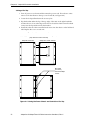
11.2 Joint Motions . . . . . . . . . . . . . . . . . . . . . . . . . . . . . . . . . . . . . . . . . . . . . . . . . . . 255
AdeptOne-XL Robot Working Envelope . . . . . . . . . . . . . .
AdeptThree-XL Robot Working Envelope . . . . . . . . . . . . .
Joint 1 . . . . . . . . . . . . . . . . . . . . . . . . . . . . . . . . . . . . . . . . . .
Joint 2 . . . . . . . . . . . . . . . . . . . . . . . . . . . . . . . . . . . . . . . . . .
Joint 3 . . . . . . . . . . . . . . . . . . . . . . . . . . . . . . . . . . . . . . . . . .
Joint 4 . . . . . . . . . . . . . . . . . . . . . . . . . . . . . . . . . . . . . . . . . .
.............
.............
.............
.............
.............
.............
255
256
256
258
258
259
11.3 AdeptOne-XL Robot Specifications . . . . . . . . . . . . . . . . . . . . . . . . . . . . . . . . 260
11.4 AdeptThree-XL Robot Specifications. . . . . . . . . . . . . . . . . . . . . . . . . . . . . . . . 262
11.5 Adept PA-4 Power Chassis Specifications . . . . . . . . . . . . . . . . . . . . . . . . . . . 264
EMC Test Information . . . . . . . . . . . . . . . . . . . . . . . . . . . . . . . . . . . . . . . . . . . 264
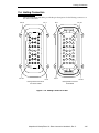
11.6 Harting Connectors . . . . . . . . . . . . . . . . . . . . . . . . . . . . . . . . . . . . . . . . . . . . . . 265
Arm Power Connector Pin Identification . . . . . . . . . . . . . . . . . . . . . . . . . . 266
11.7 Robot ID Labels . . . . . . . . . . . . . . . . . . . . . . . . . . . . . . . . . . . . . . . . . . . . . . . . . 267
AdeptOne-XL/AdeptThree-XL Robot Instruction Handbook, Rev. C
17
Table of Contents
A
Adept-XL Robot Factory Installed Options. . . . . . . . . . . . . . . . . . . . . . 269
A.1 Adept-XL Cleanroom Option . . . . . . . . . . . . . . . . . . . . . . . . . . . . . . . . . . . . . . . 269
Installation . . . . . . . . . . . . . . . . . . . . . . . . . . . . . . . . . . . . . . . . . . . . . . . . . . . . 269
Vacuum Requirements . . . . . . . . . . . . . . . . . . . . . . . . . . . . . . . . . . . . . . . . . . 269
Vacuum Installation . . . . . . . . . . . . . . . . . . . . . . . . . . . . . . . . . . . . . . . . . . . . 271
Vacuum Supply Pump. . . . . . . . . . . . . . . . . . . . . . . . . . . . . . . . . . . . 271
Pipe Size . . . . . . . . . . . . . . . . . . . . . . . . . . . . . . . . . . . . . . . . . . . . . . . 271
Vacuum Switch . . . . . . . . . . . . . . . . . . . . . . . . . . . . . . . . . . . . . . . . . 272
Testing the Vacuum . . . . . . . . . . . . . . . . . . . . . . . . . . . . . . . . . . . . . . . . . . . . 272
A.2 Adept-XL Robot IP 54 Option . . . . . . . . . . . . . . . . . . . . . . . . . . . . . . . . . . . . . . . 273
IP 54 Adept-XL Robot . . . . . . . . . . . . . . . . . . . . . . . . . . . . . . . . . . . . . . . . . . . 273
Customer Requirements. . . . . . . . . . . . . . . . . . . . . . . . . . . . . . . . . . . . . . . . . 274
Sealing the Tool Flange . . . . . . . . . . . . . . . . . . . . . . . . . . . . . . . . . . . 274
Pressurizing of the Robot . . . . . . . . . . . . . . . . . . . . . . . . . . . . . . . . . . 274
Index . . . . . . . . . . . . . . . . . . . . . . . . . . . . . . . . . . . . . . . . . . . . . . . . . . . . . . . 277
18
AdeptOne-XL/AdeptThree-XL Robot Instruction Handbook, Rev. C
List of Figures
Figure 1-1.
Adept-XL Robots . . . . . . . . . . . . . . . . . . . . . . . . . . . . . . . . . . . . . . . . . . . . . . . . 25
Figure 1-2.
Adept-XL Robot Joint Motions . . . . . . . . . . . . . . . . . . . . . . . . . . . . . . . . . . . . . 26
Figure 1-3.
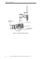
Adept MV-10 Controller and PA-4 Power Chassis . . . . . . . . . . . . . . . . . . . . . 26
Figure 1-4.
Adept-XL Robot Impact and Trapping Point Hazards . . . . . . . . . . . . . . . . . . 30
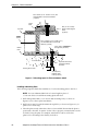
Figure 2-1.
Mounting Spool Specifications . . . . . . . . . . . . . . . . . . . . . . . . . . . . . . . . . . . . . 46
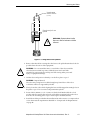
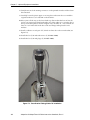
Figure 2-2.
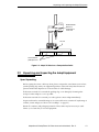
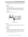
Adept-XL Robot on a Transportation Pallet . . . . . . . . . . . . . . . . . . . . . . . . . . 51
Figure 3-1.
Mounting Hole Pattern (Plate/Spool-to-Floor) . . . . . . . . . . . . . . . . . . . . . . . . 54
Figure 3-2.
Mounting Hole Pattern (Robot-to-Plate/Spool) . . . . . . . . . . . . . . . . . . . . . . . 55
Figure 3-3.
Required Clearance for Robot Cables . . . . . . . . . . . . . . . . . . . . . . . . . . . . . . 56
Figure 3-4.
Mounting Plate-to-Floor Installation Detail . . . . . . . . . . . . . . . . . . . . . . . . . . . 57
Figure 3-5.
Mounting Spool-to-Floor Installation Detail . . . . . . . . . . . . . . . . . . . . . . . . . . . 58
Figure 3-6.
Lifting Robot With Eyebolts . . . . . . . . . . . . . . . . . . . . . . . . . . . . . . . . . . . . . . . . 61
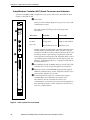
Figure 4-1.
AWC System Processor Board . . . . . . . . . . . . . . . . . . . . . . . . . . . . . . . . . . . . . . 66
Figure 4-2.
A Amplifier . . . . . . . . . . . . . . . . . . . . . . . . . . . . . . . . . . . . . . . . . . . . . . . . . . . . . . 67
Figure 4-3.
Dual B+ Amplifier . . . . . . . . . . . . . . . . . . . . . . . . . . . . . . . . . . . . . . . . . . . . . . . . 68
Figure 4-4.
Joining the Power Chassis and Controller at the Top . . . . . . . . . . . . . . . . . . 70
Figure 4-5.
Joining the Power Chassis and Controller (Bottom View) . . . . . . . . . . . . . . . 71
Figure 4-6.
Installing Mounting Brackets on an Adept MV Controller
Figure 4-7.
Installing Mounting Brackets on an Adept PA-4 Power Chassis . . . . . . . . . . 74
Figure 4-8.
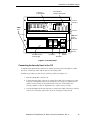
Controller Interface Panel (CIP) . . . . . . . . . . . . . . . . . . . . . . . . . . . . . . . . . . . . 75
Figure 4-9.
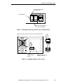
Controller Interface Panel (CIP) Side View . . . . . . . . . . . . . . . . . . . . . . . . . . . 77
. . . . . . . . . . . . . . 73
Figure 4-10. Controller Interface Panel (CIP) Back Panel View . . . . . . . . . . . . . . . . . . . . . 78
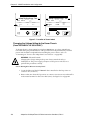
Figure 4-11. Connecting the CIP to the AWC . . . . . . . . . . . . . . . . . . . . . . . . . . . . . . . . . . . 80
Figure 4-12. MCP Connection . . . . . . . . . . . . . . . . . . . . . . . . . . . . . . . . . . . . . . . . . . . . . . . . 81
Figure 4-13. Cable Installation (Without MMSP Option) . . . . . . . . . . . . . . . . . . . . . . . . . . . 82
Figure 4-14. Adept-XL Robot Connector Locations . . . . . . . . . . . . . . . . . . . . . . . . . . . . . . 84
Figure 4-15. Robot-to-EJI Cable Installation . . . . . . . . . . . . . . . . . . . . . . . . . . . . . . . . . . . . . 85
Figure 4-16. Adept MV Controller Power Entry Board . . . . . . . . . . . . . . . . . . . . . . . . . . . . . 87
Figure 4-17. Insulating Blue Wire in Power Cord (200-240VAC) . . . . . . . . . . . . . . . . . . . . . 90
Figure 4-18. Power Labels . . . . . . . . . . . . . . . . . . . . . . . . . . . . . . . . . . . . . . . . . . . . . . . . . . . . 90
Figure 4-19. Insulating Blue Wire in Power Cord (380-415 VAC) . . . . . . . . . . . . . . . . . . . . . 92
Figure 4-20. Adept-XL Robot Ground Point . . . . . . . . . . . . . . . . . . . . . . . . . . . . . . . . . . . . . 94
Figure 5-1.
Components of a Category 3 E-Stop System . . . . . . . . . . . . . . . . . . . . . . . . . 96
Figure 5-2.
Security Panel . . . . . . . . . . . . . . . . . . . . . . . . . . . . . . . . . . . . . . . . . . . . . . . . . . . 97
Figure 5-3.
Connectors on the Control Rail . . . . . . . . . . . . . . . . . . . . . . . . . . . . . . . . . . . . 98
Figure 5-4.
Insulating Blue Wire in Power Cord (200-240 VAC) . . . . . . . . . . . . . . . . . . . . 100
Figure 5-5.
Moving Blue Wire From Neutral to AP1.L2 (200-240 VAC) . . . . . . . . . . . . . . 101
Figure 5-6.
Changing Voltage in Power Chassis . . . . . . . . . . . . . . . . . . . . . . . . . . . . . . . 101
AdeptOne-XL/AdeptThree-XL Robot Instruction Handbook, Rev. C
19
List of Figures
Figure 5-7.
Location of Power Labels . . . . . . . . . . . . . . . . . . . . . . . . . . . . . . . . . . . . . . . . . 102
Figure 5-8.
Moving Blue Wire From AP1.L2 to Neutral (380-415 VAC) . . . . . . . . . . . . . . 103
Figure 5-9.
Insulating Blue Wire in Power Cord (380-415 VAC) . . . . . . . . . . . . . . . . . . . . 104
Figure 5-10. Typical 380-415 VAC Connection for MMSP System . . . . . . . . . . . . . . . . . . . 106
Figure 5-11. Typical 3-Phase 200-240 VAC Connection for MMSP System . . . . . . . . . . . 106
Figure 5-12. Connectors on Power Rail . . . . . . . . . . . . . . . . . . . . . . . . . . . . . . . . . . . . . . . . 108
Figure 5-13. Adept-XL Robot System Grounding Diagram . . . . . . . . . . . . . . . . . . . . . . . . 110
Figure 5-14. Main Components of the Safety System . . . . . . . . . . . . . . . . . . . . . . . . . . . . 112
Figure 5-15. Category 3 E-Stop Board and Teach Restrict Interface (TRI)
Board on Control Rail 113
Figure 5-16. Category 3 E-Stop Schematic (Sheet 1 of 2) . . . . . . . . . . . . . . . . . . . . . . . . . 118
Figure 5-17. Category 3 E-Stop Schematic (Sheet 2 of 2) . . . . . . . . . . . . . . . . . . . . . . . . . 119
Figure 6-1.
Connecting the A-Series Monitor and Keyboard . . . . . . . . . . . . . . . . . . . . . 126
Figure 6-2.
AdeptWindows Installation . . . . . . . . . . . . . . . . . . . . . . . . . . . . . . . . . . . . . . . 130
Figure 6-3.
The Controller IP Address . . . . . . . . . . . . . . . . . . . . . . . . . . . . . . . . . . . . . . . . . 133
Figure 6-4.
One PC, One Controller . . . . . . . . . . . . . . . . . . . . . . . . . . . . . . . . . . . . . . . . . . 134
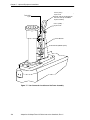
Figure 7-1.
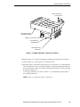
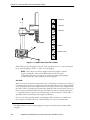
User Connector Locations on the Tower Assembly . . . . . . . . . . . . . . . . . . . . 138
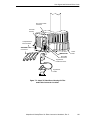
Figure 7-2.
Adept-XL Robot Base Showing Air Filter
and Cable Connector Locations 139
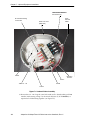
Figure 7-3.
Gripper Solenoids, Connector Locations . . . . . . . . . . . . . . . . . . . . . . . . . . . . 143
Figure 7-4.
Solenoid Valve Assembly . . . . . . . . . . . . . . . . . . . . . . . . . . . . . . . . . . . . . . . . . 144
Figure 7-5.
Tube and Cable Routing . . . . . . . . . . . . . . . . . . . . . . . . . . . . . . . . . . . . . . . . . 145
Figure 7-6.
Tower Bracket Tubing/Cable-Tie Installation . . . . . . . . . . . . . . . . . . . . . . . . . 146
Figure 7-7.
User Connections in the Adept-XL Robot . . . . . . . . . . . . . . . . . . . . . . . . . . . . 148
Figure 7-8.
Adept-XL Robot Camera Mounting Bracket . . . . . . . . . . . . . . . . . . . . . . . . . 150
Figure 7-9.
J1 Access Cover Mounting Locations for Tooling . . . . . . . . . . . . . . . . . . . . . 151
Figure 7-10. J2 Upper Cover Mounting Locations for Tooling . . . . . . . . . . . . . . . . . . . . . . 152
Figure 7-11. Micro-Style Connector Pinouts . . . . . . . . . . . . . . . . . . . . . . . . . . . . . . . . . . . . 157
Figure 7-12. JCOM Pin Locations . . . . . . . . . . . . . . . . . . . . . . . . . . . . . . . . . . . . . . . . . . . . . 158
Figure 7-13. AWC User Communication Connectors . . . . . . . . . . . . . . . . . . . . . . . . . . . . 159
Figure 7-14. JUSER 37 Pin D-sub Connector . . . . . . . . . . . . . . . . . . . . . . . . . . . . . . . . . . . . . 163
Figure 7-15. J-User 37 Pin D-sub Connector . . . . . . . . . . . . . . . . . . . . . . . . . . . . . . . . . . . . . 164
Figure 7-16. JSIO Emergency Stop Circuit . . . . . . . . . . . . . . . . . . . . . . . . . . . . . . . . . . . . . . 165
Figure 7-17. System Power Switch Circuit . . . . . . . . . . . . . . . . . . . . . . . . . . . . . . . . . . . . . . 170
Figure 7-18. System Power Switch Circuit (MMSP Option) . . . . . . . . . . . . . . . . . . . . . . . . . 171
Figure 7-19. Digital Input Wiring Examples (JSIO Connector) . . . . . . . . . . . . . . . . . . . . . . 175
Figure 7-20. Digital Output Wiring for JSIO Connector . . . . . . . . . . . . . . . . . . . . . . . . . . . . 176
Figure 8-1.
Adept-XL Robot Test Locations . . . . . . . . . . . . . . . . . . . . . . . . . . . . . . . . . . . . 188
Figure 8-2.
Brake Solenoid Valve Electrical Connectors . . . . . . . . . . . . . . . . . . . . . . . . . 195
Figure 9-1.
Holding the MCP . . . . . . . . . . . . . . . . . . . . . . . . . . . . . . . . . . . . . . . . . . . . . . . . 199
Figure 9-2.
Cradling the MCP . . . . . . . . . . . . . . . . . . . . . . . . . . . . . . . . . . . . . . . . . . . . . . . 200
20
AdeptOne-XL/AdeptThree-XL Robot Instruction Handbook, Rev. C
List of Figures
Figure 9-3.
MCP Layout . . . . . . . . . . . . . . . . . . . . . . . . . . . . . . . . . . . . . . . . . . . . . . . . . . . 201
Figure 9-4.
Data Entry Keys . . . . . . . . . . . . . . . . . . . . . . . . . . . . . . . . . . . . . . . . . . . . . . . . . 202
Figure 9-5.
MCP Predefined Function Buttons . . . . . . . . . . . . . . . . . . . . . . . . . . . . . . . . . 204
Figure 9-6.
EDIT Function Button . . . . . . . . . . . . . . . . . . . . . . . . . . . . . . . . . . . . . . . . . . . . 204
Figure 9-7.
DISPLAY Function Button . . . . . . . . . . . . . . . . . . . . . . . . . . . . . . . . . . . . . . . . . 206
Figure 9-8.
CLEAR ERROR Function Button . . . . . . . . . . . . . . . . . . . . . . . . . . . . . . . . . . . . 207
Figure 9-9.
Command (CMD) Function Button . . . . . . . . . . . . . . . . . . . . . . . . . . . . . . . . 208
Figure 9-10. Program Set Function Button . . . . . . . . . . . . . . . . . . . . . . . . . . . . . . . . . . . . . 209
Figure 9-11. Mode Control Buttons . . . . . . . . . . . . . . . . . . . . . . . . . . . . . . . . . . . . . . . . . . . 210
Figure 9-12. Speed Bars . . . . . . . . . . . . . . . . . . . . . . . . . . . . . . . . . . . . . . . . . . . . . . . . . . . . 213
Figure 9-13. WORLD State (Four-Axis SCARA) . . . . . . . . . . . . . . . . . . . . . . . . . . . . . . . . . . 214
Figure 9-14. TOOL State (Four-Axis SCARA) . . . . . . . . . . . . . . . . . . . . . . . . . . . . . . . . . . . . 215
Figure 9-15. TOOL State (Six-Axis Robot) . . . . . . . . . . . . . . . . . . . . . . . . . . . . . . . . . . . . . . . 216
Figure 9-16. JOINT State (Four-Axis SCARA) . . . . . . . . . . . . . . . . . . . . . . . . . . . . . . . . . . . . 217
Figure 9-17. JOINT State (Six-Axis Robot) . . . . . . . . . . . . . . . . . . . . . . . . . . . . . . . . . . . . . . . 218
Figure 9-18. FREE State (Four-Axis SCARA) . . . . . . . . . . . . . . . . . . . . . . . . . . . . . . . . . . . . . 219
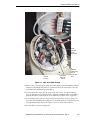
Figure 10-1. Adept-XL Robot Base Assembly . . . . . . . . . . . . . . . . . . . . . . . . . . . . . . . . . . . 224
Figure 10-2. Adept-XL Robot Upper and Lower Quill Shafts . . . . . . . . . . . . . . . . . . . . . . . 226
Figure 10-3. Joint 3 Upper Quill Shaft Lubrication . . . . . . . . . . . . . . . . . . . . . . . . . . . . . . . 227
Figure 10-4. CIP Front Panel Screws . . . . . . . . . . . . . . . . . . . . . . . . . . . . . . . . . . . . . . . . . . 231
Figure 10-5. Lamp Body Contact Alignment . . . . . . . . . . . . . . . . . . . . . . . . . . . . . . . . . . . 232
Figure 10-6. Adept MV Controller Fuse Holder . . . . . . . . . . . . . . . . . . . . . . . . . . . . . . . . . 233
Figure 10-7. Adept-XL IP 54 Robot Bolt Resealing Detail . . . . . . . . . . . . . . . . . . . . . . . . . . 235
Figure 10-8. Adept-XL Quill Bellows . . . . . . . . . . . . . . . . . . . . . . . . . . . . . . . . . . . . . . . . . . . 237
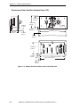
Figure 11-1. AdeptOne-XL Robot Top and Side Dimensions . . . . . . . . . . . . . . . . . . . . . . 243
Figure 11-2. AdeptThree-XL Robot Top and Side Dimensions . . . . . . . . . . . . . . . . . . . . . 244
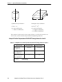
Figure 11-3. AdeptOne-XL External Equipment Mounting Area . . . . . . . . . . . . . . . . . . . 245
Figure 11-4. AdeptThree-XL External Equipment Mounting Area . . . . . . . . . . . . . . . . . . 245
Figure 11-5. Adept-XL Camera Bracket Mounting Pattern . . . . . . . . . . . . . . . . . . . . . . . 246
Figure 11-6. Adept-XL Robot Tool Flange Dimensions . . . . . . . . . . . . . . . . . . . . . . . . . . . . 247
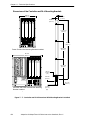
Figure 11-7. Adept MV-10 and Adept MV-5 Controller Dimensions . . . . . . . . . . . . . . . . 248
Figure 11-8. Adept PA-4 Power Chassis Dimensions . . . . . . . . . . . . . . . . . . . . . . . . . . . . . 249
Figure 11-9. Adept Controller Interface Panel (CIP) Dimensions . . . . . . . . . . . . . . . . . . . 250
Figure 11-10. MMSP Security Panel Dimensions . . . . . . . . . . . . . . . . . . . . . . . . . . . . . . . . . . 251
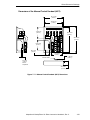
Figure 11-11. Controller and PA-4 Dimensions With Mounting Brackets Installed . . . . . . 252
Figure 11-12. Manual Control Pendant (MCP) Dimensions . . . . . . . . . . . . . . . . . . . . . . . . 253
Figure 11-13. MCP Cradle Dimensions . . . . . . . . . . . . . . . . . . . . . . . . . . . . . . . . . . . . . . . . . 254
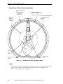
Figure 11-14. AdeptOne-XL Robot Working Envelope . . . . . . . . . . . . . . . . . . . . . . . . . . . . 255
Figure 11-15. AdeptThree-XL Robot Working Envelope . . . . . . . . . . . . . . . . . . . . . . . . . . . 256
Figure 11-16. AdeptOne-XL Joint-1 Motion . . . . . . . . . . . . . . . . . . . . . . . . . . . . . . . . . . . . . 257
AdeptOne-XL/AdeptThree-XL Robot Instruction Handbook, Rev. C
21
List of Figures
Figure 11-17. AdeptThree-XL Joint-1 Motion . . . . . . . . . . . . . . . . . . . . . . . . . . . . . . . . . . . . . 257
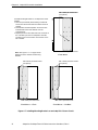
Figure 11-18. AdeptOne-XL Joint-2 LEFTY/RIGHTY Configurations . . . . . . . . . . . . . . . . . . . 258
Figure 11-19. AdeptThree-XL Joint-2 LEFTY/RIGHTY Configurations . . . . . . . . . . . . . . . . . . 258
Figure 11-20. AdeptOne-XL Joint 3 and Joint 4 Motions . . . . . . . . . . . . . . . . . . . . . . . . . . . 259
Figure 11-21. AdeptThree-XL Joint 3 and Joint 4 Motions . . . . . . . . . . . . . . . . . . . . . . . . . . 259
Figure 11-22. Harting Connector Pin Out . . . . . . . . . . . . . . . . . . . . . . . . . . . . . . . . . . . . . . . 265
Figure A-1.
Adept-XL Cleanroom Features . . . . . . . . . . . . . . . . . . . . . . . . . . . . . . . . . . . . 270
Figure A-2.
Z-Stroke and Payload . . . . . . . . . . . . . . . . . . . . . . . . . . . . . . . . . . . . . . . . . . . . 275
22
AdeptOne-XL/AdeptThree-XL Robot Instruction Handbook, Rev. C
List of Tables
Table 1-1
Adept Hardware and Software Compatibility for MMSP Systems. . . . . . . . . .27
Table 1-2
Maximum Torques and Forces (AdeptOne-XL Robot) . . . . . . . . . . . . . . . . . . .29
Table 1-3
Maximum Torques and Forces (AdeptThree-XL Robot) . . . . . . . . . . . . . . . . . .29
Table 1-4
Maximum Adept-XL Robot Joint Velocities in Runaway Situations . . . . . . . . .30
Table 1-5
Sources for International Standards and Directives . . . . . . . . . . . . . . . . . . . . .31
Table 1-6
Other Standards Related Organizations . . . . . . . . . . . . . . . . . . . . . . . . . . . . . .32
Table 1-7
Partial List of Worldwide Robot and Machinery Safety Standards . . . . . . . . .33
Table 1-8
Related Manuals . . . . . . . . . . . . . . . . . . . . . . . . . . . . . . . . . . . . . . . . . . . . . . . . . .42
Table 2-1
Mounting Plate Specifications . . . . . . . . . . . . . . . . . . . . . . . . . . . . . . . . . . . . . . .45
Table 2-2
Robot System Operating Environment Requirements . . . . . . . . . . . . . . . . . . .47
Table 2-3
Adept MV Controller Power Requirements . . . . . . . . . . . . . . . . . . . . . . . . . . . .48
Table 2-4
Adept PA-4 Power Chassis Power Requirements . . . . . . . . . . . . . . . . . . . . . . .49
Table 2-5
Adept Shipping Crate Specifications . . . . . . . . . . . . . . . . . . . . . . . . . . . . . . . . .49
Table 4-1
System Cable Lengths . . . . . . . . . . . . . . . . . . . . . . . . . . . . . . . . . . . . . . . . . . . . .83
Table 4-2
Adept MV Controller Power Cord Specifications . . . . . . . . . . . . . . . . . . . . . . .88
Table 4-3
AC Power Cord Specifications for Power Chassis . . . . . . . . . . . . . . . . . . . . . . .93
Table 5-1
AC Power Cord Specifications for Power Chassis . . . . . . . . . . . . . . . . . . . . . .107
Table 5-2
Connecting Power Cord of the Power Chassis to the Terminals on the
Power Rail (X2). . . . . . . . . . . . . . . . . . . . . . . . . . . . . . . . . . . . . . . . . . . . . . . . . . .108
Table 5-3
Customer-Supplied AC Power Cord Specifications for Security Panel. . . . .109
Table 5-4
Connection of Main AC Power Cord to the Circuit Breaker on the
Power Rail (X2). . . . . . . . . . . . . . . . . . . . . . . . . . . . . . . . . . . . . . . . . . . . . . . . . . .109
Table 5-5
Terminal Assignments on TB4 for Customer-Supplied E-Stop Switches . . . . .114
Table 5-6
Terminal Assignment on TB5 for Passive E-Stop Contacts . . . . . . . . . . . . . . .116
Table 5-7
Description of Numbers in the MMSP 3 E-Stop Drawing . . . . . . . . . . . . . . . . .120
Table 5-8
DIO Input Specifications for TB1 and TB2 on the Security Panel . . . . . . . . . .121
Table 5-9
Digital Input Signal Assignments on Terminal Blocks TB1 and TB2 . . . . . . . . .122
Table 5-10
DIO Output Specifications for TB3 . . . . . . . . . . . . . . . . . . . . . . . . . . . . . . . . . . .123
Table 5-11
Digital Output Signal Assignments on Terminal Block TB3 . . . . . . . . . . . . . . .123
Table 7-1
Pinouts for User Connectors . . . . . . . . . . . . . . . . . . . . . . . . . . . . . . . . . . . . . . . .140
Table 7-2
Nylon Tubing Lengths . . . . . . . . . . . . . . . . . . . . . . . . . . . . . . . . . . . . . . . . . . . . .142
Table 7-3
User Air Line Command Summary. . . . . . . . . . . . . . . . . . . . . . . . . . . . . . . . . . .147
Table 7-4
Pin Assignment on 9-Pin Connector J240 for Gripper Solenoid Signals . . . .148
Table 7-5
AdeptOne-XL Initial Payload and GAIN.SET Tuning Values for Joint 4 . . . . .154
Table 7-6
AdeptThree-XL Initial Payload and GAIN.SET Tuning Values for Joint 4 . . . .155
Table 7-7
JCOM Connector Pin Assignments . . . . . . . . . . . . . . . . . . . . . . . . . . . . . . . . . .158
Table 7-8
RS-232/Term Connector Pin Assignments . . . . . . . . . . . . . . . . . . . . . . . . . . . . .159
Table 7-9
RS-422/485 Connector Pin Assignments . . . . . . . . . . . . . . . . . . . . . . . . . . . . . .160
AdeptOne-XL/AdeptThree-XL Robot Instruction Handbook, Rev. C
23
List of Tables
Table 7-10
Contacts Provided by the JUSER Connector . . . . . . . . . . . . . . . . . . . . . . . . . 161
Table 7-11
Remote MCP Connections on the JUSER Connector . . . . . . . . . . . . . . . . . . 162
Table 7-12
DIO Input Circuit Specifications (JSIO Connector) . . . . . . . . . . . . . . . . . . . . 173
Table 7-13
DIO Output Specifications (JSIO Connector) . . . . . . . . . . . . . . . . . . . . . . . . . 175
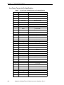
Table 7-14
JSIO Digital I/O Connector Pin Assignments . . . . . . . . . . . . . . . . . . . . . . . . . . 177
Table 8-1
LED Status Indicators . . . . . . . . . . . . . . . . . . . . . . . . . . . . . . . . . . . . . . . . . . . . . 183
Table 9-1
Robots With More Than 6 Axes . . . . . . . . . . . . . . . . . . . . . . . . . . . . . . . . . . . . . 220
Table 10-1
Recommended Preventive Maintenance Schedule . . . . . . . . . . . . . . . . . . 221
Table 10-2
Adept MV Controller Fuse Ratings . . . . . . . . . . . . . . . . . . . . . . . . . . . . . . . . . . 233
Table 10-3
Controller Spare Parts List From Adept . . . . . . . . . . . . . . . . . . . . . . . . . . . . . . 240
Table 10-4
Controller Spare Parts List From Third Parties . . . . . . . . . . . . . . . . . . . . . . . . . . 240
Table 10-5
PA-4 Spare Parts List . . . . . . . . . . . . . . . . . . . . . . . . . . . . . . . . . . . . . . . . . . . . . . 241
Table 10-6
IP 54 and Adept-XL Clean Room Robot Spare Parts List . . . . . . . . . . . . . . . . 241
Table 11-1
AdeptOne-XL Robot Performance Specifications . . . . . . . . . . . . . . . . . . . . 260
Table 11-2
AdeptOne-XL Robot Softstop and Hardstop Specs. . . . . . . . . . . . . . . . . . . . 261
Table 11-3
AdeptThree-XL Robot Performance Specifications . . . . . . . . . . . . . . . . . . . 262
Table 11-4
AdeptThree-XL Robot Softstop and Hardstop Specs . . . . . . . . . . . . . . . . . . . 263
Table 11-5
Power Consumption for PA-4 Power Chassis . . . . . . . . . . . . . . . . . . . . . . . . . 264
Table 11-6
Arm Power Harting Connector Pin Identification . . . . . . . . . . . . . . . . . . . . . 266
Table 11-7
Motor Winding Resistance Check . . . . . . . . . . . . . . . . . . . . . . . . . . . . . . . . . . 267
Table A-1
Pipe Fitting Flow Equivalents (in Feet of Straight Pipe). . . . . . . . . . . . . . . . . . 271
Table A-2
IP 54 Hardware Upgrade Kit . . . . . . . . . . . . . . . . . . . . . . . . . . . . . . . . . . . . . . . 274
24
AdeptOne-XL/AdeptThree-XL Robot Instruction Handbook, Rev. C
Safety
1
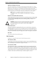
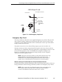
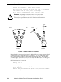
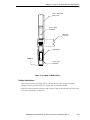
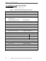
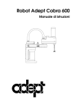
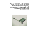
The Adept-XL robots are four-axis SCARA1 robots (see Figure 1-1). Joints 1, 2, and 4 are
rotational; joint 3 is translational. See Figure 1-2 for a description of the robot joint
locations.
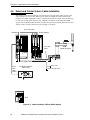
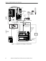
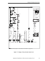
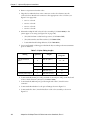
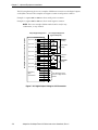
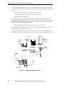
The Adept-XL robots require an Adept MV series controller and a PA-4 power chassis (see
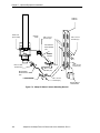
Figure 1-3 on page 26). The robot is programmed and controlled using the Adept MV
controller and PA-4 amplifier control system. The optional Manual Mode Safety Package
(MMSP) provides additional safety features (see Figure 5-1 on page 96). Specifications for
the Adept-XL series of robots are provided in Chapter 11.
adept
adept
AdeptThree-XL Robot
AdeptOne-XL Robot
Figure 1-1. Adept-XL Robots
1
Selective Compliance Assembly Robot Arm
AdeptOne-XL/AdeptThree-XL Robot Instruction Handbook, Rev. C
25
Chapter 1 - Safety
Joint 2
Joint 1
Joint 3
adept
Joint 4
Figure 1-2. Adept-XL Robot Joint Motions
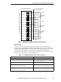
AWC
SF
A
B
D
SCR
EVI
EJI
STP ES
A AMP
A AMP
DO NOT REMOVE OR INSTALL THIS
MODULE UNLESS HIGH VOLTS LED
IS COMPLETELY EXTINGUISHED.
DO NOT REMOVE OR INSTALL THIS
MODULE UNLESS HIGH VOLTS LED
IS COMPLETELY EXTINGUISHED.
B+ AMP
VGB
HPE
OK
1
2
3
4
5
6
C
VME
VI
D
E
O
B
U
S
V
I
D
E
O
HIGH VOLTS ON
B
U
S
DO NOT REMOVE OR INSTALL THIS
MODULE UNLESS HIGH VOLTS LED
IS COMPLETELY EXTINGUISHED.
HIGH VOLTS ON
HIGH VOLTS ON
PWM ON
PWM ON
PWM ON
LOW VOLTS ON
LOW VOLTS ON
LOW VOLTS ON
OPEN CKT FAULT
OPEN CKT FAULT
HV SAG/OVER TEMP
HV SAG/OVER TEMP
A PHASE SHORT FAULT
A PHASE SHORT FAULT
B PHASE SHORT FAULT
B PHASE SHORT FAULT
C PHASE SHORT FAULT
C PHASE SHORT FAULT
DO NOT REMOVE THIS PANEL UNLESS
SYSTEM POWER IS OFF AND AMPLIFIER
HIGH VOLTS LED(S) IS COMPLETELY
EXTINGUISHED. DO NOT OPERATE
WITHOUT THIS PANEL INSTALLED.
OPEN CKT FAULT
HV SAG/OVER TEMP
SHORT FAULT
B1
B2
M
O
N
I
T
O
R
B1
AMPLIFIER
SIGNAL
1
C
O
N
T
R
O
L
C
O
N
T
R
O
L
S
I
G
N
A
L
S
I
G
N
A
L
A
M
P
L
I
F
I
E
R
2
3
4
1 2 3 4
ON
C
A
M
E
R
A
S
/
S
T
R
O
B
E
S
ARM
SIGNAL
T
E
A
C
H
C
O
N
T
R
O
L
BELT
ENCODER
R
E
S
T
R
I
C
T
B2
P
O
I
N
T
E
R
M
O
T
O
R
M
O
T
O
R
P
O
W
E
R
P
O
W
E
R
O
U
T
P
U
T
O
U
T
P
U
T
KEYBOARD
M
O
T
O
R
P
O
W
E
R
O
U
T
P
U
T
®
USE ONLY WITH
250V FUSES
WARNING:
FOR CONTINUED PROTECTION
AGAINST RISK OF FIRE,
REPLACE ONLY WITH SAME
TYPE AND RATING OF FUSE.
adept
technology, inc.
5AF
~100-240V
50/60HZ
MVMV-10
Controller
With
Controller
AWC
Board
With AWC Module
Adept PA-4 Power
Adept PA-4
Chassis
Figure 1-3. Adept MV-10 Controller and PA-4 Power Chassis
26
AdeptOne-XL/AdeptThree-XL Robot Instruction Handbook, Rev. C
Definition of a Manipulating Industrial Robot
An automatically controlled, reprogrammable, multipurpose, manipulative machine with
several degrees of freedom, which may be either fixed in place or mobile for use in
industrial automation applications is called a manipulating robot. (ISO 10218:1992(E))
Adept Equipment Compatibility
This instruction handbook describes the installation and commissioning of Adept-XL
robots (with and without the Manual Mode Safety Package). The optional Manual Mode
Safety Package (MMSP) provides a Category 3 level of safety, as specified in EN 954, in
section 1.3 on page 33.
The Adept robot system as described in this handbook must consist of the hardware and
software listed in the following table. All new systems shipped from the factory will
include the correct equipment as shown. If you have existing Adept equipment, this table
can help distinguish new equipment from older equipment, especially since some of it is
visibly similar. See the product data label for the robot, controller, and power chassis for
model number or part number information.
For information on the V+ operating system, refer to the V+ Operating System User’s Guide.
Table 1-1. Adept Hardware and Software Compatibility for MMSP Systems
Product
Required Model, Part, or Version Number
AdeptOne-XL robot
203 mm (8 in.) quill option
356 mm (14 in.) quill option
Model Number 860
part number 30862-10301
part number 30862-10304
AdeptThree-XL robot
Model Number 862
part number 30862-10300
Adept MV-10 controller
part number 30340-40000
Adept MV-5 controller
part number 30340-10000
Adept PA-4 power amplifier chassis
part number 30336-31000
A power amplifier
part number 10337-15200
Dual B+ power amplifier
part number 10338-51000
Manual Mode Safety Package (MMSP)
Option consisting of:
Category 3 Security Panel
part number 30335-00000
B+ power amplifier
with voltage restrict
Controller Interface Panel (CIP)
part number 90338-51010
part number 30350-10350 (Category 1)
part number 30350-10350 (Category 3)
Manual Control Pendant III
part number 90332-48050 (MCP III)
V+ operating system software
Version 13.0 or later
AdeptOne-XL/AdeptThree-XL Robot Instruction Handbook, Rev. C
27
Chapter 1 - Safety
1.1
Notes, Cautions, and Warnings
There are four levels of special notation used in this instruction handbook. In descending
order of importance, they are:
!
WARNING: If the actions indicated in a “WARNING” are not complied
with, injury or major equipment damage could result. A Warning
statement will typically describe the potential hazard, its possible effect,
and the measures that must be taken to reduce the hazard.
WARNING: If the WARNING is indicated with a lightning bolt instead of
an exclamation mark, an electrical danger or shock is possible for
personnel working with the system.
!
CAUTION: If the action specified in the “CAUTION” is not complied with,
damage to your equipment could result.
NOTE: A “NOTE” provides supplementary information, emphasizes a
point or procedure, or gives a tip for easier operation.
1.2
Precautions and Required Safeguards
This manual must be read by all personnel who install, operate, or maintain Adept
systems, or who work within or near the workcell.
WARNING: Adept Technology strictly prohibits installation,
commissioning, or operation of an installation with an Adept robot
without adequate safeguards according to applicable local and national
standards. Installations in EU and EEA countries must comply with
EN 775/ISO 10218, sections 5,6; EN 292-1; and EN 60204, section 13.
28
AdeptOne-XL/AdeptThree-XL Robot Instruction Handbook, Rev. C
Precautions and Required Safeguards
Maximum Robot Forces and Torques
Adept robots are computer-controlled mechanisms capable of exerting considerable force.
Like all robot and motion systems, and most industrial equipment, they must be treated
with respect by the user and the operator. (See Table 1-2 and Table 1-3.)
Table 1-2. Maximum Torques and Forces (AdeptOne-XL Robot)
Torque
Force
Joint 1 maximum static torque
330 N•m (244 ft-lb)
Joint 2 maximum static torque
255 N•m (188 ft-lb)
Maximum static force applied by the robot in XY plane,
measured at the tool flange (joint 2 fully tucked)
1187 N (267 lb)
Table 1-3. Maximum Torques and Forces (AdeptThree-XL Robot)
Torque
Force
Joint 1 maximum static torque
330 N•m (244 ft-lb)
Joint 2 maximum static torque
255 N•m (188 ft-lb)
Maximum static force applied by the robot in XY plane,
measured at the tool flange (joint 2 fully tucked)
1179 N (265 lb)
Safety Barriers
Safety barriers must be an integral part of robot workcell design. Adept systems are
computer-controlled, and may activate remote devices under program control at times or
along paths not anticipated by personnel. It is critical that safeguards be in place to
prevent personnel from entering the workcell whenever equipment power is present.
The robot system integrator, or end user, must ensure that adequate safeguards, safety
barriers, light curtains, safety gates, safety floor mats, etc., will be installed. The robot
workcell must be designed according to the applicable local and national standards (see
section 1.8 on page 38).
The safe distance to the robot depends on the height of the safety fence. The height and
the distance of the safety fence from the robot must ensure that personnel cannot reach the
danger zone of the robot (see section 1.8 on page 38).
The Adept control system has features that aid the user in constructing system safeguards,
including customer emergency stop circuitry and digital input and output lines. The
emergency power-off circuitry is capable of switching external power systems, and can be
interfaced to the appropriate user-supplied safeguards. See Chapter 5 for information on
safe and effective use of the robot.
AdeptOne-XL/AdeptThree-XL Robot Instruction Handbook, Rev. C
29
Chapter 1 - Safety
Impact and Trapping Points
Impact
Impact!
Trapping
(Pinch)
Points
Trapping
(Pinch)
Points
®
®
Figure 1-4. Adept-XL Robot Impact and Trapping Point Hazards
Adept robots are capable of moving at high speeds. If a person is struck by a robot
(impacted) or trapped (pinched), death or serious injury could occur. Robot configuration,
joint speed, joint orientation, and attached payload all contribute to the total amount of
energy available to cause injury.
Hazards From Expelling a Part or Attached Tooling
The maximum joint tip speeds that can be achieved by the Adept-XL robot in a runaway
situation are listed in Table 1-4. Any tooling, fixtures, end-effectors, etc., mounted to the
user flange, outer link, or inner link of the robot must be attached by sufficient means to
resist being expelled from the robot. Additionally, any payload must be held by the
end-effector in a manner that prevents the payload from being expelled accidentally.
Table 1-4. Maximum Adept-XL Robot Joint Velocities in Runaway Situationsa
Joint Max Angular/Linear Velocity
AdeptOne-XL
AdeptThree-XL
Joint 1 maximum angular velocity
1118 degrees/second
920 degrees/second
Joint 1 maximum linear velocity
10.4 meters/second
10.7 meters/second
Joint 2 maximum angular velocity
1869 degrees/second
1670 degrees/second
Joint 2 maximum linear velocity
31.8 meters/second
35.3 meters/second
a
These velocities can occur only in a runaway or mechanical failure situation. These
are not performance specifications (see Chapter 11 for robot performance
specifications).
The safety fence or barrier constructed around the robot must be designed to withstand
the impact of any item expelled accidentally from the robot. Projectile energy can be
calculated using the formula E = 1/2mv2. Here are two examples.
Example 1: 4 kg payload mounted to end-effector, joint 2 at 0° and all other joints
stationary.
30
AdeptOne-XL/AdeptThree-XL Robot Instruction Handbook, Rev. C
Precautions and Required Safeguards
maximum possible projectile energy = 1/2 (4 kg) (17.1 m/s)2 = 584 J (431 ft-lb)
Example 2: 6 kg payload mounted to elbow (Joint 2).
maximum possible projectile energy = 1/2 (6 kg) (10.7 m/s)2 = 343 J (253 ft-lb)
Additional Safety Information
The standards and regulations listed in this handbook contain additional guidelines for
robot system installation, safeguarding, maintenance, testing, start-up, and operator
training. The table below lists some sources for the various standards.
Table 1-5. Sources for International Standards and Directives
BSI, British Standards Institute
Sales Department
Linford Wood
Milton Keynes
MK14 6LE
United Kingdom
Phone 0181 996 7000
Fax 0181 996 7001
http://www.bsi.org.uk
Beuth Verlag GmbH
10722 Berlin
Germany
Phone 030 26 01 - 22 60
Fax
030 26 01 - 12 60
http://www.din.de/en/beuth/Beuth.html
IEC, International Electrotechnical Commission
Rue de Varembe 3
PO Box 131
CH-1211 Geneva 20, Switzerland
Phone 41 22 919-0211
Fax 41 22 919-0300
http://www.iec.ch
American National Standards Institute (ANSI)
11 West 42nd Street, 13th Floor
New York, NY 10036, USA
Phone 212-642-4900
Fax 212-398-0023
http:/www.ansi.org
Document Center, Inc.
1504 Industrial Way, Unit 9
Belmont, CA 94002, USA
Phone 415-591-7600
Fax 415-591-7617
http://www.doccenter.com
AdeptOne-XL/AdeptThree-XL Robot Instruction Handbook, Rev. C
31
Chapter 1 - Safety
Table 1-5. Sources for International Standards and Directives (Continued)
Global Engineering Documents
15 Inverness Way East
Englewood, CO 80112, USA
Phone 800-854-7179
Fax 303-397-2740
http://global.ihs.com
Robotic Industries Association (RIA)
900 Victors Way
PO Box 3724
Ann Arbor, MI 48106, USA
Phone 313-994-6088
Fax 313-994-3338
http://www.robotics.org
Table 1-6. Other Standards Related Organizations
American Electronics Association (AEA) Europe
40 rue des Drapiers
1050 Brussels, Belgium
Phone 011-32-502-7015
Fax 011-32-2-502-6734
http://web1.aeanet.org/homepage/europe/council.html
http://www.aeanet.org
32
AdeptOne-XL/AdeptThree-XL Robot Instruction Handbook, Rev. C
Risk Assessment
1.3
Risk Assessment
Without special safeguards connected to its control system, the Adept-XL robot could
inflict serious injury to an operator working within its work envelope. Safety standards in
several countries require that appropriate safety equipment be installed as part of the
system. Table 1-7 lists some of the safety standards that affect industrial robots. This is not
a complete list. You must comply with all applicable local and national standards for
where the robot is installed.
Table 1-7. Partial List of Worldwide Robot and Machinery Safety Standards
International
USA
Canada
ISO 10218
Europe
EN 775
ANSI/RIA
R15.06
CAN/CSA-
Title of Standard
Manipulating Industrial Robots Safety
Industrial Robots and Robot Systems
- Safety Requirements
Z434-94
EN 292
Safety of Machinery - Basic
Concepts, General Principles for
Design
EN 954-1
Safety Related Parts of Control
Systems - General Principles for
Design
EN 1050
Safety of Machinery - Risk
Assessment
Applicable US standards include ANSI/RIA R15.06. Applicable European standards
include EN 775, EN 954, and EN 1050. Applicable international standards include
ISO 10218.
Adept has performed a risk assessment for this product, based on the intended
applications of the robot. For normal operation, AUTO mode, user-supplied interlocked
guarding must be installed to prevent anybody entering the workcell while High Power is
on.
The risk assessment for teaching this product depends on the application. In many
applications, the programmer will need to enter the robot workcell while High Power is
enabled to teach robot locations. Other applications can be designed so that the
programmer does not have to enter the work envelope while High Power is on. Examples
of alternative methods of programming include:
1.
Programming from outside the safety barrier.
2.
Programming with High Power off (using brake release button).
3.
Copying program from another (master) robot.
4.
Off-line or CAD programming.
AdeptOne-XL/AdeptThree-XL Robot Instruction Handbook, Rev. C
33
Chapter 1 - Safety
1.4
Risk Assessment – Category 1
Installations Not Requiring Programmer to Enter Workcell
!
!
WARNING: The Adept-supplied system components provide a
Category 1 control system as defined by EN 954. The robot system must
be installed with user-supplied interlock barriers. The interlocked barrier
should interrupt the AC supply to the PA-4 power chassis in the event of
personnel attempting to enter the workcell when High Power is enabled,
even for teaching in Manual mode. The user-designed interlocks
themselves should be designed to provide a Category 3 level of control
per EN 954. Failure to install suitable guarding could result in death or
injury.
WARNING: If the programmer needs to enter the workcell when High
Power is ON, Adept’s risk assessment indicates that a Category 3 control
system is required.
Some teaching methods do not require the programmer to enter the workcell. If these
methods are used exclusively, the robot should be installed with interlocked guarding to
ensure AC power is removed from the PA-4 power chassis whenever a person enters the
workcell.
In situations with low exposure consideration factors, EN 1050 specifies use of a
Category 1 Control System per EN 954. EN 954 defines a Category 1 Control System as
one that employs Category B components designed to withstand environmental
influences, such as voltage, current, temperature, and EMI and that employs well-tried
safety principles. The standard Adept-XL control system (system without MMSP Control
System) described in this handbook employs hardware components in its safety system
that meet or exceed the requirements of the EU Machinery Directive and Low Voltage
Directives.
Furthermore, the standard control system is fully hardened to all EMI influences per the
EU EMC Directive and meets all functional requirements of ISO 10218 (EN 775)
Manipulating Robots Safely. In addition, a software-based reduced speed and “soft-servo”
mode has been incorporated to limit speed and impact forces on the Operator and
production tooling when the robot is operated in Manual Mode.
In consideration of the above, the standard AdeptOne-XL/AdeptThree-XL control system
meets or exceeds the requirements imposed by the EN 954 specified Category 1 level of
safety, as evidenced by the Manufacturer’s Declaration of Conformity at the front of this
handbook.
Adept has performed a risk assessment based on intended applications of this product.
Our assessment indicates that a Category 3 safety system, as defined in EN 954, is
required to protect the operator and programmer. This protection may take two forms:
1. If a programmer may need to enter the cell with High Power on, then Adept’s
optional MMSP should be installed. The system must be installed so that no one
can enter the workcell when the robot is in AUTO mode.
34
AdeptOne-XL/AdeptThree-XL Robot Instruction Handbook, Rev. C
Intended Use of the Robots
2. If no one will enter the workcell with High Power ON, not even to teach robot
locations, then the user must provide a Category 3, dual-channel and cross
checked, interlocked barrier system. The system must disconnect the AC power
supply to the robot if any person enters the workcell.
Installations Requiring Programmer to Enter Workcell
The Manual Mode Safety Package (MMSP) is available for the Adept XL family of robots.
The MMSP protects a person teaching robot locations while inside the user-provided
safety barrier, with High Power ON.
As a consequence of:
1. The potential for fatal injury,
2. The high probability that an operator could not avoid being hit by the robot in a
high-acceleration, runaway, failure condition,
EN 1050 specifies use of a Category 3 Control System per EN 954. EN 954 defines a
Category 3 Control System as one in which:
1. No single failure can cause a loss of the safety function.
2. Any failure that does occur can be “checked” prior to enabling power.
The optional Manual Mode Safety Package (MMSP) described in this handbook employs a
fully redundant Emergency Stop that incorporates “Teach Restrict” sensors and
self-checking hardware. Through use of a thorough Failure Mode and Effect Analysis, it
has been determined that the MMSP, when installed and operated as described in this
handbook, meets the stringent requirements of the Category 3 level of safety specified in
EN 954. The MMSP has also been designed to meet relevant standards referenced in
EN 954, including ISO 10218 (EN 775) Manipulating Robots Safely. Also see the
Manufacturer’s Declaration on page 5.
Adept has performed a risk assessment based on intended applications of this product.
Our assessment indicates that a Category 3 safety system, as defined in EN 954, is
required to protect the operator and programmer. This protection may take two forms:
1. If a programmer may need to enter the cell with High Power on, then Adept’s
optional MMSP should be installed. The system must be installed so that no one
can enter the workcell when the robot is in AUTO mode
2. If no one will enter the workcell with High Power ON, not even to teach robot
locations, then the user must provide a Category 3, dual-channel and cross
checked, interlocked barrier system. The system must disconnect the AC power
supply to the robot if any person enters the workcell.
1.5
Intended Use of the Robots
The installation and use of Adept products must comply with all safety instructions and
warnings in this manual. Installation and use must also comply with all applicable local
and national requirements and safety standards (see section 1.8 on page 38).
AdeptOne-XL/AdeptThree-XL Robot Instruction Handbook, Rev. C
35
Chapter 1 - Safety
The AdeptOne-XL robot is intended for use in small parts assembly and material
handling for payloads typically less than 12 kg (26.5 lb). A HyperDrive option is available
for this robot that delivers higher power to the joint 1 and 2 motors. This option is used for
applications that require faster throughput.
The AdeptThree-XL robot is intended for use in parts assembly and material handling for
payloads less than 25 kg (55 lb) and for those applications that require a longer reach than
the AdeptOne-XL robot.
!
WARNING: For safety reasons, it is prohibited to make certain
modifications to Adept robots (see section 1.6).
The Adept MV controller and the Adept PA-4 power chassis are component
subassemblies of a complete industrial automation system. The controller and power
chassis subassemblies must be installed inside a suitable enclosure. The controller and
power chassis subassemblies must not come into contact with liquids. Additionally, a
standard Adept-XL robot must not come into contact with liquids. (An Adept-XL robot
equipped with the IP 54 option can withstand some moisture contact.)
The Adept equipment is not intended for use in any of the following situations:
• In hazardous (explosive) atmospheres
• In mobile, portable, marine, or aircraft systems
• In life-support systems
• In residential installations
• In situations where the Adept equipment will be subject to extremes of heat or
humidity. See Table 2-2 on page 47 for allowable temperature and humidity
ranges.
!
WARNING:
The instructions for operation, installation, and maintenance given in this
Instruction Handbook must be strictly observed.
Non-intended use of an Adept-XL robot can:
• Cause injury to personnel
• Damage the robot or other equipment
• Reduce system reliability and performance
All persons that install, commission, operate, or maintain the robot must:
• Have the necessary qualifications
• Read and follow exactly the instructions in this Instruction Handbook
If there is any doubt concerning the application, ask Adept to determine if it is an
intended use or not.
36
AdeptOne-XL/AdeptThree-XL Robot Instruction Handbook, Rev. C
Robot Modifications
1.6
Robot Modifications
It is sometimes necessary to modify the robot in order to successfully integrate it into a
workcell. Unfortunately, many seemingly simple modifications can either cause a robot
failure, or reduce the robot’s performance, reliability, or lifetime. The following
information is provided as a guideline to modifications.
Acceptable Modifications
In general, the following robot modifications will not cause problems, but may affect
robot performance:
• Attaching tooling, utility boxes, solenoid packs, vacuum pumps, screwdrivers,
cameras, lighting, etc., to the inner link, outer link, or column.
• Attaching hoses, pneumatic lines, or cables to the robot. These should be designed
so they do not restrict joint motion or cause robot motion errors.
• See Figure 7-9 on page 151 and Figure 7-10 on page 152 for allowable mounting
hole positions.
Unacceptable Modifications
The modifications listed below may damage the robot, reduce system safety and
reliability, or shorten the life of the robot.
!
CAUTION: Making any of the modifications outlined below will void the
warranty of any components that Adept determines were damaged due
to the modification. You must contact Adept Customer Service if you are
considering any of the following modifications.
• Modifying any of the robot harnesses or robot-to-controller cables.
• Modifying any drive system components, except as noted in Chapter 7.
• Modifying, including drilling or cutting, any robot casting is prohibited with the
exception of the access covers for joint 1 and joint 2 and the quill cover (see
Figure 7-9 on page 151 and Figure 7-10 on page 152).
• Modifying any robot electrical component or printed-circuit board.
• Routing additional hoses, air lines, or wires through the robot.
• Modifications that compromise EMC performance, including shielding
modifications to cables.
1.7
Transport
Always use adequate equipment to transport and lift Adept products. See Chapter 2 for
more information on transporting, lifting, and installing.
WARNING: Do not remain under the robot while it is transported.
!
AdeptOne-XL/AdeptThree-XL Robot Instruction Handbook, Rev. C
37
Chapter 1 - Safety
1.8
Safety Requirements for Additional Equipment
Additional equipment used with the Adept-XL robot (grippers, conveyor belts, etc.) must
not reduce the workcell safeguards.
All emergency stop switches must always be accessible.
If the robot is to be used in an EU or EEA member country, all components in the robot
workcell must comply with the safety requirements in the European Machine Directive
89/392/EEC (and subsequent amendments) and related harmonized European,
international, and national standards. For robot systems, these include: EN 775/ISO
10218, sections 5,6; EN 292-1, 3.71; and EN 60204, section 13. For safety fences, see EN 294.
In other countries, Adept strongly recommends, in addition to complying with the
applicable local and national regulations, that a similar level of safety be obtained.
In the USA, applicable standards include ANSI/RIA R15.06 and ANSI/UL 1740.
In Canada, applicable standards include CAN/CSA Z434.
1.9
Sound Emissions
The sound emission level of the Adept-XL robot depends on the speed and payload. The
maximum value is 90dB. (This is at maximum AUTO-mode speed.)
1.10 Thermal Hazard
!
WARNING: Thermal Hazard!
You can burn yourself. Do not touch the robot base or outer link shortly
after the robot has been running at high ambient temperatures (40-50°C)
(104-122°F) or at fast cycle times (over 60 cycles per minute). The robot
skin/surface temperature can exceed 70°C (158°F).
1.11 Working Areas
Adept robots have a Manual and an Automatic (AUTO) operating mode. While in
Automatic Mode, personnel are not allowed in the workcell.
In Manual Mode, operators with additional safety equipment (see section 1.13 on page 40)
are allowed to work in the robot workcell if the MMSP option incorporated. For safety
reasons the operator should, whenever possible, stay outside of the robot work envelope
to prevent injury. The maximum speed and power of the robot is reduced but it could still
cause injury to the operator.
Before performing maintenance in the working envelope of the robot, High Power must
be switched off and the power supply of the robot must be disconnected. After these
precautions, a skilled person is allowed to maintain the robot. See section 1.12 on page 39
for the specifications.
38
AdeptOne-XL/AdeptThree-XL Robot Instruction Handbook, Rev. C
Qualification of Personnel
The Adept-XL robot can work in Automatic Mode at high speeds and accelerations and
can trap persons or crush them. The impact of a robot can kill a person.
WARNING:
Electrical Hazard!
Impact Hazard!
Never remove any safeguarding and never make changes in the system
that will decommission a safeguard.
1.12 Qualification of Personnel
This manual assumes that all personnel have attended an Adept training course and have
a working knowledge of the system. The user must provide the necessary additional
training for all personnel who will be working with the system.
As noted in this handbook, certain procedures should be performed only by skilled or
instructed persons. For a description of the level of qualification, Adept uses the standard
terms:
• Skilled persons have technical knowledge or sufficient experience to enable them
to avoid the dangers, electrical and/or mechanical.
• Instructed persons are adequately advised or supervised by skilled persons to
enable them to avoid the dangers, electrical and/or mechanical.
All personnel must observe sound safety practices during the installation, operation, and
testing of all electrically powered equipment. To avoid injury or damage to equipment,
always remove power by disconnecting the AC power from the source before attempting
any repair or upgrade activity. Use appropriate lockout procedures to reduce the risk of
power being restored by another person while you are working on the system.
!
WARNING: The user must get confirmation from every entrusted person
before they start working with the robot that the person:
1. Has received the instruction handbook
2. Has read the instruction handbook
3. Understands the instruction handbook and
4. Will work in the manner specified by the instruction handbook.
AdeptOne-XL/AdeptThree-XL Robot Instruction Handbook, Rev. C
39
Chapter 1 - Safety
1.13 Safety Equipment for Operators
Adept advises operators to wear extra safety equipment in the workcell. For safety
reasons operators must wear the following when they are in the robot workcell.
• Safety glasses
• Protective headgear (hard hats)
• Safety shoes
Install warning signs around the workcell to ensure that anyone working around the
robot system knows they must wear safety equipment.
1.14 Protection Against Unauthorized Operation
The system must be protected against unauthorized use. Restrict access to the keyboard
and the Manual Control Pendant by locking them in a cabinet or use another adequate
method to prevent access to them.
1.15 Safety Aspects While Performing Maintenance
Only skilled persons with the necessary knowledge about the safety and operating
equipment are allowed to maintain the robot, controller, and power chassis.
!
WARNING: During maintenance and repair, the power of the Adept PA-4
power chassis and the Adept MV controller must be turned off.
Unauthorized third parties must be prevented from turning on power
through the use of fail-safe lockout measures. (Turn off the circuit
breakers, lock the cabinet, and remove the key!)
1.16 Risks That Cannot Be Avoided
For Systems with MMSP Option
The Manual Mode Safety Package (MMSP) Category 3 Adept-XL robot control system
implementation has a series of electromechanical devices that disable High Power if a
system failure occurs.
The following situations may result in risks that cannot be avoided:
• Purposely defeating any aspect of the safety E-Stop system
• Improper installation or programming of the robot system
• Use of cables other than those supplied or use of modified components in the
system
• Failure of a second device in a redundant safety circuit
Take precautions to ensure that these situations do not occur (see Chapter 10).
40
AdeptOne-XL/AdeptThree-XL Robot Instruction Handbook, Rev. C
What to Do in an Emergency Situation
For Systems Without MMSP Option
The following situations may result in risks that cannot be avoided:
• Purposely defeating any aspect of the safety E-Stop system
• Improper installation or programming of the robot system
• Unauthorized use of cables other than those supplied or use of modified
components in the system
• Defeating interlock so that operator can enter workcell with High Power ON
Take precautions to ensure that these situations do not occur (see Chapter 10).
1.17 What to Do in an Emergency Situation
Press any E-Stop button (a red push-button on a yellow background/field) and then
follow the internal procedures of your company or organization for an emergency
situation. If a fire occurs, use CO2 to extinguish the fire.
!
WARNING: Do not disconnect the compressed air supply to the robot
unless you are sure that nobody is trapped near the robot. Disconnecting
the air supply will prevent the brake release function from operating.
This function may be required to release or gain access to a person
trapped in the workcell.
1.18 How Can I Get Help?
Refer to the How to Get Help Resource Guide (Adept P/N 00961-00700) for details on getting
assistance with your Adept software or hardware.
You can obtain this document through Adept On Demand. The phone numbers are:
(800) 474-8889 (toll free)
(503) 207-4023 (toll call)
Please request document number 1020.
AdeptOne-XL/AdeptThree-XL Robot Instruction Handbook, Rev. C
41
Chapter 1 - Safety
1.19 Related Manuals
This manual covers the installation and maintenance of an Adept-XL robot system. There
are additional manuals that cover programming the system, reconfiguring installed
components, and adding additional optional components. The following manuals
(available on the documentation CD-ROM provided with each system) provide
information on advanced configurations and system specifications.
Table 1-8. Related Manuals
Manual Title
Description
Adept MV Controller User’s
Guide
00330-01040
Describes the configuration and interface options for all Adept
supplied processor boards and components that can be installed
in an Adept control system.
AdeptWindows User’s Guide
00963-07300
Describes complex network installations, installation and use of
NFS server software, the Adept Windows Offline Editor, and the
AdeptWindows DDE software.
Instructions for Adept Utility
Programs
00963-00000
Describes the utility programs used for advanced system
configurations, system upgrades, file copying, and other system
configuration procedures
V+ Operating System User’s
Guide
00963-02300
Describes the V+ operating system including, disk file
operations, monitor commands, and monitor command
programs.
V+ Language User’s Guide
00963-013000
Describes the V+ language and programming of an Adept
control system.
42
AdeptOne-XL/AdeptThree-XL Robot Instruction Handbook, Rev. C
Installation Overview
2
This chapter covers the facility electrical and mechanical specifications and other general
installation requirements.
The next several chapters cover the installation of the robot, the robot control system,
optional Adept-supplied equipment, and optional user-supplied equipment. In general, a
complete installation will proceed as described in the following chapters:
• Chapter 3 covers installing the robot.
• Chapter 4 covers installation of the control system and power amplifiers.
• Chapter 5 covers installation and configuration of the optional Manual Mode
Safety Package (MMSP). Complete the installation instructions in this chapter only
if you have the MMSP option.
• Chapter 6 covers selection and installation of a user interface.
• Chapter 7 covers installation of optional equipment.
Once the physical installation is complete, the installation must be verified and the system
must be commissioned.
• Chapter 8 covers verifying that the installation is correct and commissioning the
system.
2.1
Hardware to Be Provided by User
The user must supply the following minimum hardware. Your system may include
additional user-supplied equipment as described in Chapter 7.
All Systems
• Mounting plate or spool (see “Mounting Surface Specifications” on page 45)
• Installation tools (see “Tool and Equipment Requirements” on page 53)
• End-effector (see “Installing End-Effectors on an Adept-XL Robot” on page 153)
• Safety barrier (see “Safety Barriers” on page 29)
• Ground wire for robot (see “Adept Robot Grounding” on page 93)
• Ground wire for robot-mounted equipment (see “Robot-Mounted Equipment
Grounding” on page 94)
• Optional AC 10A contactor
AdeptOne-XL/AdeptThree-XL Robot Instruction Handbook, Rev. C
43
Chapter 2 - Installation Overview
Systems Without MMSP Option
• Optional 24VDC power supply (see “System Power Switch” on page 76)
Systems With MMSP Option
• 5-wire power cord for security panel (see “Changing the Power Chassis Voltage
Setting” on page 89)
• Ground wire for security panel (see “Grounding an MMSP Equipped System” on
page 110)
2.2
Facility Requirements
Compressed Air Requirements
The Adept-XL robot requires clean, dry, oil-free, compressed air at 4.8 – 7.6 bar (70-110 psi)
with a flow rate of 28 liters per minute (1 SCFM). This compressed air is used to release the
robot brakes and optionally to provide air to the User air lines. End-effectors attached to
the robot may require additional air flow. Insufficient air pressure or flow will cause the
brakes to engage, which will disable High Power.
!
CAUTION: Failure to supply clean, dry, oil-free air may result in damage
to mechanical, electrical, or pneumatic components inside the robot.
The user must supply all tubing and fittings to plumb the facility air supply to the robot.
The robot is supplied with an air filter with a standard 1/4-inch Industrial Interchange
nipple (1/4 NPT type thread). The compressed air to the robot must meet the
specifications listed above. Also see Figure 7-7 on page 148.
!
WARNING: The compressed air supply must be fed from a source that
normally remains ON during an emergency stop. Disconnecting the air
supply will prevent the brake release from operating. In an emergency,
the brake release may be required to release or gain access to a person
trapped in the workcell. Any manually operated isolation valves that
could be used to interrupt the compressed air supply to the robot should
be clearly labeled to indicate that the supply should be left ON in an
emergency.
NOTE: An air filter is supplied in the robot accessory kit and should be
installed on the robot prior to connecting the compressed air supply.
44
AdeptOne-XL/AdeptThree-XL Robot Instruction Handbook, Rev. C
Facility Requirements
Mounting Surface Specifications
The floor at the installation site must be concrete with a minimum thickness of 100 mm
(4-in.) and must comply with all national and local codes. The floor should be level. Due
to the high torque (405 N•m [432 ft-lb] at the base) transmitted by the robot, it must be
mounted to an extremely rigid structure. Any mounting structure vibration or flexing will
seriously degrade robot performance. Adept recommends using either a mounting plate
or a mounting spool. Both have proven reliable over extended periods of use. If another
type of mounting structure is used, it must adequately resist vibration and flexure.
Plate
Using a flat steel plate is mandatory if the robot is to be mounted directly to the facility
floor. The mounting plate should conform to the following specifications:
Table 2-1. Mounting Plate Specifications
Material
carbon steel
Diameter, minimum
610 mm (24.0 inches)
Thickness, minimum
25 mm (1.0 inch)
Mounting surface flatness
within 0.5 mm (0.02 inch)
Mounting hole pattern
as shown in Figure 3-2
Mounting surface level
must be level to within ±0.3 degrees (±2.5 mm
[0.1 in.] for a 610 mm [24 in.] spool)a
a
For MMSP equipped systems, the mounting surface must be level to within
±0.25 degrees.
WARNING: The specification for leveling the mounting surface is critical
on MMSP systems. The Teach Restrict sensor in the outer link will not
function properly if the robot is not level.
!
Spool
Another method of mounting uses a steel spool. See Figure 2-1 on page 46 for the
specifications and dimensions of a robot spool. All of the specifications for the mounting
plate in the previous section apply to the top plate of the mounting spool.
The recommended design for a manufactured spool is a welded assembly consisting of
three steel parts, top and bottom plates welded to a center column as detailed in
Figure 2-1.
AdeptOne-XL/AdeptThree-XL Robot Instruction Handbook, Rev. C
45
Chapter 2 - Installation Overview
610 mm dia.
(24.0 in.)
TopPlate
Plate
Top
25 mm (1.0 in.)
Top
Topand
and
Bottom
Bottom
10 mm
(3/8 in.)
457 mm max.
(18.0 in.)
Column
Column
A
A
Bottom
Plate
Bottom Plate
25 mm (1.0 in.)
10 mm
(0.40 in.)
min.
305 mm dia.
(12 in.)
(12
(12in.
in.Schedule
Schedule 40
40 IPS
IPSororequiv.)
equiv.)
305 mm Sq.
(12 in.)
4 x 10 mm
(3/8 in.) min.
View
A-A
View
A-A
View
ViewA-A
A-A
Option 1
Option 2
Option
2
Option 1
Material:
Carbon Steel
Material Surface Flatness: 0.5 mm (0.02 in.)
• Material: Carbon Steel • Mounting Surface Flatness: 0.5 mm (0.02")
• MountingSurface
SurfaceLevel:
Level:within
within±±0.25
(±2.5 mm [0.1 in.]
diameter)
Mounting
0.25 degrees
degrees (±2.5mm
in.] over
over 610
610mm
mm[24
[24in.]
in.])
Figure 2-1. Mounting Spool Specifications
See Figure 3-2 on page 55 for the robot mounting hole pattern.
46
AdeptOne-XL/AdeptThree-XL Robot Instruction Handbook, Rev. C
Environmental Requirements
2.3
Environmental Requirements
The Adept robot system installation must meet the operating environment requirements
shown in Table 2-2. See Table 2-3 on page 48 for the Adept MV controller electrical
requirements and Table 2-4 on page 49 for the PA-4 amplifier chassis electrical
requirements.
Table 2-2. Robot System Operating Environment Requirements
Ambient temperature
Adept-XL robot
5°C to 50°C (41°F to 122°F)
controller – while accessing floppy or
hard drive
5°C to 40°C (41°F to 104°F)
controller – while not accessing floppy or
hard drive
5°C to 50°C (41°F to 122°F)
power chassis
5°C to 40°C (41°F to 104°F)
Humidity
5 to 90%, non-condensing
Altitude
up to 2000 m (6500 ft.)
Pollution degree
2 (IEC 1131-2/EN 61131-2)
Free space around Adept MV controller and
power chassis (for proper cooling)
25 mm (1-inch) in front,
15 mm (1/2-inch) at top
Robot protection class
IP20 (NEMA Type 1)
A robot that meets IP54 standards is
available. See “IP 54 Adept-XL Robot” on
page 273.
Controller and power chassis subassembly
protection class, unmounted
IP20 (NEMA Type 1)
Recommendations for customer-supplied
enclosure for Adept controller and power
chassis. (Mandatory for installations in EU or
EEA countries)
Enclosure should meet EN 60204 (IEC 204)
requirements and be rated at IP54. Also,
enclosure must provide a method of locking
the enclosure power-disconnect in the OFF
position.
NOTE: See Chapter 11 for robot, Adept MV controller, and PA-4 power
chassis dimensions.
AdeptOne-XL/AdeptThree-XL Robot Instruction Handbook, Rev. C
47
Chapter 2 - Installation Overview
2.4
Power Requirements
Adept MV Controller Power Requirements
Table 2-3. Adept MV Controller Power Requirements
Auto-Ranging
Nominal
Voltage Ranges,
Minimum
Operating
Voltagea
Maximum
Operating
Voltage
100V to 120V
and
200V to 240V
90V
132V
180V
264V
Frequency/
Phasing
50-60Hz,
1-phase
Recommended
External Circuit
Breaker
(user-supplied)
10 amps
Power to the Adept MV controller and all amplifiers and motion devices must come
from a single source.
a
The maximum interruption time (operating voltage below specification) tolerated by
the controller is 16 milliseconds.
Facility Overvoltage Protection
The user must protect the controller from excessive overvoltages and voltage spikes. If the
country of installation requires a CE-certified installation, or compliance with IEC 1131-2,
the following information may be helpful: IEC 1131-2 requires that the installation must
ensure that Category II overvoltages (i.e., line spikes not directly due to lightning strikes)
are not exceeded. Transient overvoltages at the point of connection to the power source
shall be controlled not to exceed overvoltage Category II, i.e., not higher than the impulse
voltage corresponding to the rated voltage for the basic insulation. The user-supplied
equipment or transient suppressor shall be capable of absorbing the energy in the
transient.
In the industrial environment, nonperiodic overvoltage peaks may appear on mains
power supply lines as a result of power interruptions to high energy equipment (such as a
blown fuse on one branch in a 3-phase system). This will cause high current pulses at
relatively low voltage levels. The user shall take the necessary steps to prevent damage to
the controller system (such as by interposing a transformer). See IEC 1131-4 for additional
information.
48
AdeptOne-XL/AdeptThree-XL Robot Instruction Handbook, Rev. C
Before Unpacking the Adept Equipment
PA-4 Power Chassis Power Requirements
Table 2-4. Adept PA-4 Power Chassis Power Requirementsa
Nominal
Voltage
Range
Frequency/
Phasing
Minimum
Operating
Voltage
Maximum
Operating
Voltage
Recommended
External
Circuit Breaker
(user-supplied)
380 to 415
VAC
50-60Hz,
3-phase with
neutral
342 VAC
424 VAC
20 amps
200 to 240
VAC
50-60Hz,
3-phase
180 VAC
245 VAC
20 amps
Power to the Adept MV controller and PA-4 power chassis must come from a single
source.
a
2.5
Specifications for the Adept power chassis are based on two A and one B+
amplifier modules and an Adept-XL robot.
Before Unpacking the Adept Equipment
Carefully inspect all shipping crates for evidence of damage during transit. If any damage
is indicated, request that the carrier’s agent be present at the time the container is
unpacked.
2.6
Adept Shipment Specifications
Adept ships the equipment in a number of boxes and shipping crates, depending on the
sales order. The boxes have different dimensions and weights. The following table gives
an overview.
Table 2-5. Adept Shipping Crate Specifications
Product in Crate
Length
Width
Height
Weight
AdeptOne-XL Robot
0.74 m (29 in.)
1.20 m (47 in.)
2.00 m (79 in.)
265 kg (583 lb)
AdeptThree-XL Robot
0.74 m (29 in.)
1.20 m (47 in.)
2.00 m (79 in.)
266 kg (585 lb)
Adept MV Controller and
PA-4 Power Chassis
0.89 m (35 in.)
0.64 m (25 in.)
0.96 m (38 in.)
66 kg (145 lb)
Monitor
0.54 m (21 in.)
0.51 m (20 in.)
0.51 m (20 in.)
23 kg (50 lb)
AdeptOne-XL/AdeptThree-XL Robot Instruction Handbook, Rev. C
49
Chapter 2 - Installation Overview
!
2.7
WARNING: The center of gravity of the robot shipping crates is not in the
middle of the boxes. Pay attention when you transport the crates.
Transport and Storage
Shipping and Storage
This equipment must be shipped and stored in a temperature controlled environment,
within the range -25°C to +55°C. The recommended humidity range is 5 to 90 percent,
non-condensing. It should be shipped and stored in the Adept-supplied packaging, which
is designed to prevent damage from normal shock and vibration. You should protect the
package from excessive shock and vibration.
Use a forklift, pallet jack, or similar device to transport and store the packaged equipment
(see Figure 2-2 on page 51).
!
WARNING: Heavy load!
Do not attempt to transport the robot boxes by hand. Always use a pallet
jack, forklift, etc.
The robots must always be stored and shipped in an upright position in a clean, dry area
that is free from condensation. Do not lay the crate on its side or any other position, this
could damage the robot.
2.8
Lifting and Handling
Before Unpacking
Carefully inspect all shipping crates for evidence of damage during transit. Pay special
attention to tilt and shock indication labels on the exteriors of the containers. If any
damage is indicated, request that the carrier’s agent be present at the time the container is
unpacked.
50
AdeptOne-XL/AdeptThree-XL Robot Instruction Handbook, Rev. C
Unpacking and Inspecting the Adept Equipment
Brake
Brake Release
Release
Button
Button on
Underside
of
on Inner Link
Inner Link
Air Line
Air Line
Place forklift or
Place forklift
pallet-jack
hereor
pallet-jack here
Figure 2-2. Adept-XL Robot on a Transportation Pallet
2.9
Unpacking and Inspecting the Adept Equipment
Upon Unpacking
Before signing the carrier’s delivery sheet, please compare the actual items received (not
just the packing slip) with your equipment purchase order and verify that all items are
present and that the shipment is correct and free of visible damage.
If the items received do not match the packing slip, or are damaged, do not sign the
receipt. Contact Adept as soon as possible.
If the items received do not match your order, please contact Adept immediately.
Inspect each item for external damage as it is removed from its container. If any damage is
evident, contact Adept (see “How Can I Get Help?” on page 41).
Retain all containers and packaging materials. These items may be necessary to settle
claims or, at a later date, to relocate equipment.
AdeptOne-XL/AdeptThree-XL Robot Instruction Handbook, Rev. C
51
Chapter 2 - Installation Overview
2.10 Repacking for Relocation
If the robot or other equipment needs to be relocated, reverse the steps in the installation
procedures that follow this chapter. Reuse all original packing containers and materials
and follow all safety notes used for installation. Improper packaging for shipment will
void your warranty. Before unbolting the robot from the plate or spool, fold the outer arm
against the joint 2 hardstops to help centralize the center of gravity. The robot must always
be shipped in an upright orientation. Specify this to the carrier if the robot is to be
shipped.
2.11 Robot and Controller ID Labels
Identification (ID) labels are located on the left or back side of the controller and power
chassis. On the label you will find the model and serial numbers and the voltage and
current ratings (see Figure 4-18 on page 90). Smaller serial number labels are located on
the front of the chassis near the On/Off switch. The robot ID label is located on the right
side of the robot base, toward the rear. You should always have this serial number
available when you call Adept Customer Service for technical support.
52
AdeptOne-XL/AdeptThree-XL Robot Instruction Handbook, Rev. C
Robot Installation
3.1
3
Mounting the Robot
Adept robots must always be installed on a base. The base can be a mounting plate or a
mounting spool (see “Mounting Surface Specifications” on page 45).
WARNING: You must not install a robot directly on the floor.
!
Tool and Equipment Requirements
Common hand tools, plus the following items, are required to install the robot and any
options or end-effectors:
• Power Drill Motor, 12 mm (1/2-inch) capacity, minimum
• Masonry drill bit, 22 mm (7/8-inch)
• Ratchet handle, 1/2-inch drive
• Socket, 3/4-inch
• Device for measuring mounting surface level that exceeds the level requirements
described in Table 2-1 on page 45.
• Torque wrench, 1/2-inch drive
• Vacuum cleaner
• Pallet jack (or forklift)
• Hydraulic lift with dual-leg sling (both rated for 320 kg [700 pounds] minimum)
• Mounting plate or spool
!
WARNING: The installation procedures in this chapter should be
performed only by skilled persons, as defined in section 1.12 on page 39.
Do not attempt the installation without proper tools, including a torque
wrench and a device for measuring level. An improper installation could
cause serious damage or possible fatal injury.
AdeptOne-XL/AdeptThree-XL Robot Instruction Handbook, Rev. C
53
Chapter 3 - Robot Installation
Installing a Base for the Robot
Adept recommends that you use a mounting plate or a mounting spool. The following
sections detail preparing and installing a plate or a spool. The plate or spool must meet
the specifications detailed in ”Mounting Surface Specifications” on page 45.
Robot Installation Dimension Drawings
Figure 3-1 shows the dimensions for drilling the holes to mount the plate or spool to the
floor.
Figure 3-2 shows the hole pattern for drilling the holes to mount the robot to the plate or
spool.
Figure 3-3 shows the clearance required at the rear of the robot for the power and signal
cables.
Figure 3-4 shows mounting plate installation details.
Figure 3-5 shows mounting spool installation details.
Ø 559 mm
(22.0 in.)
Ø 610 mm
(24.0 in.)
4 x 90˚
Ø16 mm
(5/8 in.)
(4x)
Figure 3-1. Mounting Hole Pattern (Plate/Spool-to-Floor)
54
AdeptOne-XL/AdeptThree-XL Robot Instruction Handbook, Rev. C
Mounting the Robot
353.1 mm
(13.90 in.)
176.5 mm
(6.95 in.)
Clearanceholes
holes
Clearance
in
robot
mm
(3) inbase:
robot14.2
base:
(0.56
thru in.)
14.2 in.)
mmØ(0.56
(3 places)
170.9 mm
(6.73 in.)
128.3 mm
(5.05 in.)
541.0 mm
(21.3 in.)
346.5 mm
(13.64 in.)
218.2 mm
(8.59 in.)
241.8 mm
(9.52 in.)
Center
Centerofof
Column
Column(column
diameter is
179.5 mm (7 in))
23.6 mm
(0.93 in.)
447.0 mm
(17.60 in.)
Figure 3-2. Mounting Hole Pattern (Robot-to-Plate/Spool)
AdeptOne-XL/AdeptThree-XL Robot Instruction Handbook, Rev. C
55
Chapter 3 - Robot Installation
Required Robot Arm and Signal Cable Clearance
At least 254 mm (10 in) of clearance is required behind the robot so the power and signal
cables do not have excessively tight bends.
NOTE: Clearance behind the rear of
the robot must be at least 10 inches
for Arm Power and Signal/User Cables.
Arm
ArmPower
PowerCable
Cable
Ø 20.955 mm
(0.825 in.)
254 mm
(10.0 in.)
Robot Base
Robot
Base
Y
RIT L
CU NE 2
SE PA ER
US
ER
1
US
Arm
Signal Cable
Signal/User
Cable
Ø 15.875 mm
(0.625 in.)
ARM SIGNAL
Figure 3-3. Required Clearance for Robot Cables
56
AdeptOne-XL/AdeptThree-XL Robot Instruction Handbook, Rev. C
Mounting the Robot
M12 x 60 mm (or 1/2 - 13 UNC x 2.5-inch)
M12 xHex
60mm
(or Bolt
1/2 -13
UNC
x 2.5 in.)
Head
With
Lock
100mm
(or 1/2
-13 UNC
M12 x 100M12
(or x1/2
- 13 UNC
x 4-inch)
Hex Head
Bolt Washers
With Lock
and Flat
xBolt
4 in.)With
HexLock
Head Bolt With
Hex
Head
and Flat
Washers (3 places)
(3 Places)
Lock and Flat Washers
and Flat Washers
(4 Places)(4 places)
Robot
Robot
Base
Base
16 mm (5/8 in.)
inch)
Plate-To-Floor
Plate-to-Floor
Through Hole (4 Places)
Mounting
Mounting
Plate
Plate
M12 (or 1/2 -13 UNC)
M12 (or 1/2 - 13 UNC)
Robot-To-Plate
Robot-To-Plate
Tapped Holes
Tapped Hole
(3 places)
(3 Places)
Drawing Not to Scale
Drawing not to scale
Concrete Floor
Concrete Floor
90 mm
(3.5 in.)
Expansion Bolt Anchor
Expansion
Bolt
Anchor
(Thread-End
Down)
(threaded end down)
(4 Places)
(4 Places)
22 mm (7/8 in.)
Diameter Floor Holes
22 mm (7/8-inch) dia.
(4 Places)
Floor Holes
(4 Places)
Figure 3-4. Mounting Plate-to-Floor Installation Detail
AdeptOne-XL/AdeptThree-XL Robot Instruction Handbook, Rev. C
57
Chapter 3 - Robot Installation
M12 x 60 mm (or 1/2 - 13 UNC x 2.5-inch)
M12
60mm
(orWith
1/2Lock
-13 UNC
x 2.5
in.) Hex
HexxHead
Bolt
and Flat
Washers
Head
Bolt With Lock and Flat Washers
(3 Places)
(3 places)
Robot
Base
Robot Base
M12 (or
(or 1/2
1/2 -13
M12
- 13UNC)
UNC)
Robot-To-Plate Tapped
Robot-To-Spool
Holes Hole
Tapped
(3 Places)
places)
(3
Top
Top Plate
Plate
Center
Center
Column
Column
M12 x 100mm (or 1/2 -13 UNC x 4 in.)
M12
x 100 mm
1/2 Lock
- 13 UNC
4-inch)
Hex Head
Bolt(or
With
and xFlat
Hex
Head Bolt
With Lock and Flat Washers
Washers
(4 places)
(4 Places)
16 mm
Spool-to-Floor
16 mm
(5/8 (5/8
inch)in.)
Spool-To-Floor
Through
(4 Places)
Through
HoleHole
(4 Places)
Bottom
Bottom
Plate
Plate
ConcreteFloor
Floor
Concrete
90 mm
(3.5-inch)
Expansion
Bolt
Anchor
Expansion
Bolt
Anchor
(Thread-End
Down)
(threaded
end down)
(4(4Places)
Places)
Drawing
Not
Drawing
notto
toScale
scale
22 mm (7/8 in.)
22 mm (7/8-inch) dia.
Diameter Floor
Floor Holes
Holes
(4 Places)
(4
Places)
Figure 3-5. Mounting Spool-to-Floor Installation Detail
Installing a Mounting Plate
The following sequence details the installation of a robot-mounting plate to the floor:
NOTE: You can substitute M12 bolts of correct length in place of
1/2-13 UNC bolts to install the mounting plate and robot.
1. Drill and tap three M12 (or 1/2-13 UNC-2B) mounting holes, as shown in
Figure 3-2, for robot-to-plate attachment.
2. Drill four 16 mm (5/8-inch) diameter through holes, as shown in Figure 3-1, for
plate-to-floor anchoring.
3. Place the plate exactly where the robot is to be installed. Ensure that the plate is
positioned so that the “footprint” for the robot is properly oriented relative to the
workcell. Using the plate as a template, transfer the locations of the four
plate-to-floor mounting holes directly to the floor.
58
AdeptOne-XL/AdeptThree-XL Robot Instruction Handbook, Rev. C
Mounting the Robot
4. Set the plate aside and drill four holes, 22 mm (7/8-inch) in diameter by 90 mm
(3.5 inches) deep, in the floor at the locations identified in step 3.
5. Using a vacuum cleaner, remove all chips and debris from the holes, drilled in
step 4, and surrounding area.
6. Insert an expansion bolt anchor into each of the four holes in the floor. Ensure that
the threaded end of each bolt anchor is toward the bottom of each hole, as shown
in Figure 3-4.
7. Reposition the plate over the anchor holes in the floor using care to align the four
plate-to-floor holes with the anchor holes. Ensure that the plate is positioned so
that the “footprint” for the robot is properly oriented to the workcell.
8. Verify that the top (mounting) surface of the plate is level (ensure that the
accuracy of the device used to level the plate exceeds the required leveling
tolerances). The surface must be horizontal within ±0.25 degrees (MMSP), or ±0.3
degrees (no MMSP). If the plate is not level, insert shims between the plate and the
floor to bring the plate within specifications. The shims should be at least 75 mm
(3 inches) in diameter and have cutouts provided to fit around the anchor bolts.
9. Insert a M12 x 100 mm (or 1/2 - 13 UNC x 4-inch) bolt, fitted with a lock washer
and a flat washer, through the holes in the plate into each of the four plate-to-floor
anchor holes. Tighten the bolts to 55 N•m (40 ft-lb) of torque.
10. Recheck the robot mounting surface of the plate and reinsert shims as required to
bring the mounting surface horizontal within ±0.25 degrees (MMSP), or ±0.3
degrees (no MMSP).
Installing a Mounting Spool
The following sequence details the installation of the robot-mounting spool to the floor
(see Figure 3-5).
NOTE: You can substitute M12 bolts of correct length in place of
1/2-13 UNC bolts to install mounting spool and robot.
1. Drill and tap three M12 (or 1/2-13 UNC-2B) mounting holes (through) in the top
of the spool, as shown in Figure 3-2, for robot-to-spool attachment.
2. Prepare the bottom of the mounting spool by drilling four 16 mm (5/8-inch)
diameter through holes, as shown in Figure 3-1, for spool-to-floor anchoring.
3. Place the spool exactly where the robot is to be installed. Ensure that the spool is
positioned so that the footprint for the robot is properly oriented to the workcell.
Transfer the locations of the four spool-to-floor mounting holes directly to the
floor.
4. Set the spool aside and drill four holes, 22 mm (7/8-inch) in diameter by 90 mm
(3.5-inch) deep, in the floor at the locations identified in step 3.
5. Using a vacuum cleaner, remove all chips and debris from the holes, drilled in
step 4, and surrounding area.
6. Insert an expansion bolt anchor into each of the four holes in the floor. Ensure that
the threaded end of each bolt anchor is toward the bottom of each hole, as shown
in Figure 3-5.
AdeptOne-XL/AdeptThree-XL Robot Instruction Handbook, Rev. C
59
Chapter 3 - Robot Installation
7. Reposition the spool over the anchor holes in the floor taking care to align the four
spool-to-floor holes with the anchor holes. Ensure that the spool is positioned so
that the “footprint” for the robot is properly oriented to the workcell.
8. Verify that the top (mounting) surface of the plate is level (ensure that the
accuracy of the device used to level the plate exceeds the required leveling
tolerances). The surface must be horizontal within ±0.25 degrees (MMSP), or ±0.3
degrees (no MMSP). If the spool is not level, insert shims between the spool and
the floor to bring the spool within specifications. The shims should be at least 75
mm (3 inches) in diameter and have cutouts provided to fit around the anchor
bolts.
9. Insert a M12 x 100 mm (or 1/2-13 UNC x 4-inch) bolt, fitted with a lock washer
and a flat washer, through the holes in the spool into each of the four
spool-to-floor anchor holes. Tighten the bolts to 55 N•m (40 ft-lb) of torque.
10. Recheck the robot-mounting surface of the spool and reinsert shims as required to
bring the mounting surface horizontal within ±0.25 degrees, or ±0.3 degrees
without MMSP.
Mounting a Robot on a Base
The following sequence describes the installation of the robot to the mounting plate or
spool.
NOTE: You can substitute M12 bolts of correct length in place of
1/2-13 UNC bolts to install mounting spool and robot.
1. Connect the hydraulic lift to the eyebolts at the top of the robot by means of a
dual-leg sling; see Figure 3-6. Take up any slack, but do not lift the robot.
!
60
WARNING: Impact Hazard!
Do not attempt to lift the robot at any points other than the eyebolts
provided. Failure to comply could result in the robot falling and causing
either personnel injury or equipment damage.
AdeptOne-XL/AdeptThree-XL Robot Instruction Handbook, Rev. C
Mounting the Robot
Spreader Width
Spreader
Nominal: 19.8 mm
width
(7.7 in.)
Nominal:
195.8 mm
(7.7-inch)
Lift Robot Only From Two
Lift
robot only from
Eyebolts
two eyebolts.
!
WARNING:
Must
Notnot
Be
WARNING:Eyebolts
Eyebolts
must
Removed.
Robot
Calibration
Will
Be
be removed or robot calibration
Affected.
will be affected.
Figure 3-6. Lifting Robot With Eyebolts
2. Remove the three bolts securing the robot base to the pallet. Retain these bolts for
possible later relocation of the equipment.
!
WARNING: Do not extend the inner or outer links of the robot until the
robot has been secured in position. With the inner and outer links
extended, an unsecured robot will tip and fall causing either personnel
injury or equipment damage.
3. Lift the robot and position it directly over the floor plate or spool.
!
WARNING: Impact Hazard!
The robot may swing free if not lifted straight up. Stand clear of the robot
at all times while it is supported by the lift.
4. Slowly lower the robot while aligning the base and the tapped mounting holes in
the plate or spool. Do not remove the permanent eyebolts.
5. Insert a M12 x 60 mm (or 1/2 -13 UNC x 2.5-inch) bolt fitted with both a lock
washer and a flat washer through each of the three mounting holes in the robot
base into the mounting plate or spool and torque to 90 N•m (65 ft-lb).
6. Install the air filter provided in the installation kit and connect to a compressed air
source the meets the requirements detailed in ”Compressed Air Requirements”
on page 44.
AdeptOne-XL/AdeptThree-XL Robot Instruction Handbook, Rev. C
61
Chapter 3 - Robot Installation
3.2
Using the Brake Release Button
Brakes
The Adept-XL robot has fail-safe, spring-actuated, air release brakes on joints 1, 2, 3, and 4.
These brakes are engaged whenever High Power is off. The brakes are intended primarily
to restrict arm movement when high power is off, but they also assist in stopping robot
motion when the emergency stop circuitry is activated or when there is a robot motion
error. These brakes are not designed to routinely stop the robot.
Brake Release Button
To manually position the arm without turning on High Power, a brake release button is
located on the joint 1 inner link. The brake release button releases all four joints of the
Adept-XL robot (see Figure 2-2 on page 51).
The brake release function works only if a compressed air supply is connected to the
robot. The brake release function does not need electrical power and will work even if the
controller is turned off or is not connected to the robot.
3.3
Limiting Joint Travel
The joint motion or travel is limited by both software and hardware limits. The programmable software limits are known as softstops; the fixed hardware limits are referred to as
hardstops. See Table 11-2 on page 261 for the AdeptOne-XL and Table 11-4 on page 263 for
the AdeptThree-XL.
Softstops
Softstops are used when the normal motion range of the robot must be limited (if other
equipment is installed inside the envelope, for example). The softstops for each joint are
set to their maximum value at the factory. To limit any joint’s motion range, change the
joint’s softstop value using the SPEC utility program on the Adept Utility Disk supplied
with the system. Refer to the Instructions for Adept Utility Programs for information
regarding this utility program.
When you are using the MCP to move the robot, the robot will stop abruptly when it
encounters a softstop. This abruptness does not mean a hardstop has been contacted.
Hardstops
In most cases, the softstop will prevent joint travel from contacting a hardstop; however,
contact is possible during high-speed operation. The hardstops are designed to withstand
large forces without damaging the robot.
The hardstops for each joint are fixed mechanical stops. The hardstops for joints 1 and 3
are located inside the robot. The hardstops for joint 2 are mounted externally on the inner
link. The joint 2 hardstops are the hard rubber half-cylinders that the large eyebolts pass
through. The hardstops for joint 3 are mounted at the top and bottom of the quill. Joint 2
and 3 hardstops must not be modified in any way or damage to the robot could occur.
62
AdeptOne-XL/AdeptThree-XL Robot Instruction Handbook, Rev. C
Limiting Joint Travel
Cartesian Limit Stops
V+ can detect collisions between the robot end-effector and static Cartesian obstacles. V +
tests for collisions between the robot’s tool tip, or its tool-mounting flange, and specified
obstacles.
NOTE: Collisions between other structural elements of the robot and the
obstacles, or between two robots, are NOT detected.
For fixed structural elements of the workcell, the system automatically detects possible
collisions in the following circumstances:
• When planning the end point for a straight-line or joint-interpolated motion
• When executing a straight-line motion (but not during a joint-interpolated motion)
• When moving the robot in tool, world, or joint manual control
Rectangular solids (boxes), cylinders, and spheres can be defined. Objects can be placed in
any position and orientation relative to the base of the robot.
Four user obstacles can be defined and modified by the end user. The SPEC utility (see
SPEC.V2 in the Instructions for Adept Utility Programs) is used to define obstacles.
AdeptOne-XL/AdeptThree-XL Robot Instruction Handbook, Rev. C
63
Adept MV Controller
Installation
4
The Adept-XL robots are delivered with either an Adept MV-5 controller or an Adept
MV-10 controller. The dimensions, installation, and cabling requirements of both
controllers are identical. The Adept MV-10 controller allows for additional option boards.
The following sections apply whether you have an Adept MV-5 or Adept MV-10
controller. The same PA-4 power chassis is used with both controllers.
The controller chassis holds the backplane, power supply, and cooling fans required by
the various processor boards. All systems include an AWC system processor (see
Figure 4-1) and an EJI motion interface board (see Figure 4-15). These boards are delivered
with the configuration specified on your order and you should not have to perform any
setup or initialization of these boards. If you need to alter the delivered configuration or
are installing additional boards not supplied with the original order, see the Adept MV
Controller User's Guide for complete details on installing and configuring boards.
Your system may contain additional optional boards that were included as part of your
sales order. These boards also will be configured as ordered and you should not have to
perform any additional setup or configuration. For a complete description of all Adept
processor boards, see the Adept MV Controller User's Guide. The optional boards that might
be in your system are:
• Additional AWC boards used as auxiliary processors
• EVI board for the AdeptVision system
• VGB board for the standard Adept graphical user interface
• SIO board for additional hard and floppy drives and additional serial ports
• MI6/MI3 boards for controlling non-Adept robots
• DIO for supplying additional digital input and out signals
The amplifier chassis holds the backplane, power distribution, and cooling fans required
by the amplifiers. An amplifier chassis for an Adept-XL series robot contains two
single-channel amplifiers (described in “A Amplifier Module Overview” on page 67) and
one dual-channel amplifier (described in “Dual B+ Amplifier Module Overview” on page
68).
AdeptOne-XL/AdeptThree-XL Robot Instruction Handbook, Rev. C
65
Chapter 4 - Adept MV Controller Installation
AdeptWindows Controller (AWC) Board Connectors and Indicators
An AWC board (040 or 060) is required in every system. This section describes the basic
features of the AWC board.
➊
Six bicolor LEDs indicate diagnostic test, power control, and
communication status.
AWC
➊
➋
1
SF
OK
2
ES
HPE
3
HD
LAN
R
S
4
2
2
R
S
4
8
5
R
S
2
3
2
T
E
R
M
The right column of LEDs gives the following status
information:
LED Label
Red LED
Green LED
SF/OK
System Fault
System O.K.
ES/HPE
E-Stop open
High Power Enabled
HD/LAN
Read/Write from CF
Ethernet access
R
S
2
3
2
➌
➍
Status LEDs.
During system bootup the red SF/OK and ES/HPE LEDs are lit
and the red HD/LAN LED blinks. After system bootup, the
SF/OK LED should show green. If the ES/HPE LED shows red,
the E-Stop circuit is open. During compact flash reads and
writes, the HD/LAN LED pulses red. When the AWC is active
on an Ethernet network, the HD/LAN LED pulses green. See
Table 8-1, “LED Status Indicators,” on page 183 for details on
the LEDs labeled 1 - 3.
E
T
H
E
R
N
E
T
C
I
P
➋
➌
➍
Two RS232 ports and one RS422/485 port (see the Adept MV
Controller User's Guide for pin descriptions and locations).
Ethernet connector: Shielded RJ45 receptacle that supports
10 BaseT communications (see the Adept MV Controller User's
Guide and the AdeptNet User’s Guide).
Controller Interface Panel (CIP) connector that accepts a
standard 50-pin SCSI cable that routes signals and
information to the CIP. Note that the CIP does not
communicate in SCSI format (see sections 4.2 through 4.5 for
basic installation details. See the Adept MV Controller User's
Guide for complete details.
040
Figure 4-1. AWC System Processor Board
66
AdeptOne-XL/AdeptThree-XL Robot Instruction Handbook, Rev. C
A Amplifier Module Overview
A Amplifier Module Overview
The A amplifier module is a plug-in module that contains the circuitry and amplifying
components to drive the joint-1 or joint-2 motor in an Adept-XL robot. In this type of robot
system, there are two A amplifier modules in the Adept PA-4 power chassis. The A amp
module on the left-hand side, called Amp #1, drives the motor for joint 1. The A amp
module on the right-hand side, called Amp #2, drives the motor for joint 2.
Connectors and Indicators
➊
A AMP
High Volts On indicates the high voltage to the amps is
turned on.
PWM On indicates that current servo is on. It does not go on
until calibration is complete.
DO NOT REMOVE OR INSTALL THIS
MODULE UNLESS HIGH VOLTS LED
IS COMPLETELY EXTINGUISHED.
Low Volts On indicates the low voltage supply in the power
chassis is on.
HIGH VOLTS ON
➊
Status LEDs. When an LED is turned on it indicates the
following conditions:
PWM ON
LOW VOLTS ON
OPEN CKT FAULT
Open Ckt Fault indicates that an open circuit in the motor
leads has been detected.
HV SAG/OVER TEMP
A PHASE SHORT FAULT
B PHASE SHORT FAULT
C PHASE SHORT FAULT
➋
HV Sag/Over Temp indicates that the input voltage has
dropped below the specified level or an over-temperature
fault has been detected on an amp module.
A
M
P
L
I
F
I
E
R
Phase A, B, C Short Fault indicate that an over-current in the
motor leads to one of the phases has been detected.
C
O
N
T
R
O
L
➋
➌
➌
Amplifier Control connector – the EJI-to-Amp cable
connector is installed here.
Motor Power Output connector – the Arm Power cable is
installed here.
M
O
T
O
R
P
O
W
E
R
O
U
T
P
U
T
Figure 4-2. A Amplifier
AdeptOne-XL/AdeptThree-XL Robot Instruction Handbook, Rev. C
67
Chapter 4 - Adept MV Controller Installation
Dual B+ Amplifier Module Overview
The Dual B+ amplifier module is a plug-in module that contains the circuitry and amplifying components to drive two robot motors. In this type of robot system, there is one
Dual B+ amplifier module in the Adept PA-4 power chassis. This amp module, located to
the right of the A amp modules, drives the motors for joints 3 and 4.
Connectors and Indicators
➊
Dual B+ AMP
Status LEDs. The left-hand column of LED s is for the first
motor controlled by this module; the right-hand column is
for the second motor controlled by this board. When an LED
is turned on it indicates the following conditions:
High Volts On indicates the high voltage to the amps is
turned on.
DO NOT REMOVE OR INSTALL THIS
MODULE UNLESS HIGH VOLTS LED
IS COMPLETELY EXTINGUISHED.
PWM On indicates that current servo is on. It does not go on
until calibration is complete.
HIGH VOLTS ON
➊
PWM ON
LOW VOLTS ON
Low Volts On indicates the low voltage supply in the power
chassis is on.
OPEN CKT FAULT
HV SAG/OVER TEMP
SHORT FAULT
B1 B2
Note: the three LED pairs below indicate faults and are visible
momentarily before the system turns off.
B1
➋
Open Ckt Fault indicates that an open circuit in the motor
leads has been detected.
A
M
P
L
I
F
I
E
R
C
O
N
T
R
O
L
R
E
S
T
R
I
C
T
B2
M
O
T
O
R
➌
HV Sag/Over Temp left-hand LED , when lit, indicates that
the fault was caused by a sag in voltage. The right-hand LED
when lit indicates the fault was caused by an over-temperature condition on the amplifier heat sink.
T
E
A
C
H
Short Fault indicates that an over-current in the motor leads
has been detected.
➋
P
O
W
E
R
O
U
T
P
U
T
➌
Amplifier Control connector – the EJI-to-Amp cable connectors are installed here.
Teach Restrict connector – the Teach Restrict-to-B+ Amp
cable is installed here.
Motor Power Output connector – the Arm Power cable is
installed here.
Figure 4-3. Dual B+ Amplifier
68
AdeptOne-XL/AdeptThree-XL Robot Instruction Handbook, Rev. C
Joining an Adept PA-4 Power Chassis to an Adept MV Controller
4.1
Mounting the Adept MV Controller and Power Chassis
NOTE: The Adept MV controller must be installed in a suitable enclosure
that provides the environment (temperature, etc.) specified in Table 2-2,
“Robot System Operating Environment Requirements,” on page 47 and
complies with applicable local and national regulations.
The enclosure must also provide a power disconnect with a method for user service
personnel to lock the power in the OFF position. This is required for safety, including
national and international standards, such as:
• OSHA ‘Lockout/Tagout’ (USA)
• IEC 204-1
• EN 60204-1
WARNING: Failure to provide and use a suitable disconnect device could
cause death or injury to personnel.
Joining an Adept PA-4 Power Chassis to an Adept MV Controller
The Adept PA-4 power chassis can be joined to an Adept MV controller using the brackets
and screws supplied in the accessory kit. Join the chassis and controller at the top and
bottom, as described in the following paragraphs.
NOTE: Joining the chassis and controller allows rack mount of the chassis
and controller in a 19-inch rack.
AdeptOne-XL/AdeptThree-XL Robot Instruction Handbook, Rev. C
69
Chapter 4 - Adept MV Controller Installation
Joining at the Top
1. Turn off power to each unit and disconnect the power cord. Place the two units
next to each other. Remove the top cover from both (see Figure 4-4).
2. Locate the C-shaped bracket in the accessory kit.
3. Slip the bracket under the lip of the top edge of the unit on the right-hand side
and into the two slots in the edge of the chassis. Install two M4 x 8 mm flat-head
screws into the lip and down into the bracket.
4. Install the other two M4 x 8 mm flat-head screws into the chassis on the left-hand
side. Replace the cover on each unit.
(Top view with covers removed)
(Top view with covers
Adept MV Controller
PA-4 removed)
Adept Power Chassis
Adept MV Controller
Adept PA-4 Power Chassis
M4 x 8mm
(four
M4each)
x 8 mm
flat-head Phillips
(four each)
screws
flat-head
Phillips
screws
Figure 4-4. Joining the Power Chassis and Controller at the Top
70
AdeptOne-XL/AdeptThree-XL Robot Instruction Handbook, Rev. C
Space Around the Chassis
Joining at the Bottom
1. Turn the two units over so you have access to the bottom side.
2. Locate the cutout bracket in the accessory kit.
3. Place the bracket over the feet of the units as shown in Figure 4-5.
4. Install the four M4 x 8 mm flat-head screws in the holes indicated in Figure 4-5 to
secure the brackets.
!
CAUTION: Do not use screws longer than 8 mm to install the bracket.
Doing so could cause damage to your equipment.
Cutout Bracket
Cutout
Bracket
M4 xx88mm
M4
mm (x 4)
(four each)
flat-head
flat-head
Phillips
Phillips
screws
screws
AdeptMV
MV
Adept
Controller
Controller
Adept
Adept PA-4
Power
Power Chassis
Chassis
Figure 4-5. Joining the Power Chassis and Controller (Bottom View)
Space Around the Chassis
When the controller and power chassis are installed, you must allow 50 mm (2 in) at the
front of the power chassis and 25 mm (1 in) at the top and bottom of the Adept MV
controller for proper air cooling.
!
CAUTION: It is important to keep the air filters clean so the forced air
cooling system can work efficiently. See section 10.4 on page 228 for
details on cleaning the filters.
Rack or Panel Mounting
The power chassis and controller can be rack or panel mounted using the mounting
brackets that are shipped in the accessories kit. The brackets can be attached at the rear of
the controller/power chassis for panel mounting or they can be attached to the front of the
controller/power chassis for rack mounting.
AdeptOne-XL/AdeptThree-XL Robot Instruction Handbook, Rev. C
71
Chapter 4 - Adept MV Controller Installation
Panel Mounting
To panel mount the controller or power chassis, install one bracket on each side near the
back of the chassis. Use the screws and washers from the accessories kit (see Figure 4-6
and Figure 4-7).
Rack Mounting
Use the mounting brackets, screws, and washers from the accessories kit to rack-mount
the Adept PA-4 power chassis joined to an Adept MV controller in a standard 19-inch
equipment rack. The brackets can be installed in two positions for rack mounting: “flush”
and “set-back” (see Figure 4-6 and Figure 4-7).
72
AdeptOne-XL/AdeptThree-XL Robot Instruction Handbook, Rev. C
Rack or Panel Mounting
x 25mm
M4 xM4
25mm
pan-headscrews
screw
pan-head
(two(two
places)
places)
To Install Mounting Brackets on an
To Install
Mounting Brackets
Adept
MV Controller:
Adept MV
controller:
• on
Remove
(and
discard) three
existing countersunk screws from
• Remove (and discard) three
the chassis side at locations
existing countersink screws
shown
in drawing.
form side
of chassis at
• Place
bracket
in desired
position
locations shown
in drawing.
and secure with indicated M4
•screws
Place bracket
in desired
position
and washers
from
the
and secure with
accessories
kit. indicated M4
screws and washers from
• Repeat
process for the other side
accessories kit.
of the controller. If the controller is
toprocess
an Adept
•joined
Repeat
for PA-4
other power
side
of controller.
If the controller
chassis,
see Figure
4-7 for the
is joinedoftoan
PA-4
Power
location
the Adept
screws
on the
PA-4
Chassis,
the position of the screws
power
chassis.
M4 x 10mm
M4 x 10mm
pan-head
pan-head
screw
screw
is different on the side of the
contoller.
Note: See Figure 11-11 on page 252
(See
drawing for
chassis.)and
for
dimensions
of power
the controller
mounting brackets.
PanelMount
Mount
Panel
M4x x25mm
25mm
M4
pan-head
screws
pan-head screws
(twoplaces
placeseach
(two
each
Rack
Mount)
rack
mount)
M4 x 10mm
pan-head
screw
M4 x 10mm
pan-head
(one
placescrew
each
(one
place
each
rack
mount)
Rack Mount)
Rack
Flush
Rack Mount
Mount —
– Flush
Rack Mount — Set Back
Rack Mount – Set-Back
Figure 4-6. Installing Mounting Brackets on an Adept MV Controller
AdeptOne-XL/AdeptThree-XL Robot Instruction Handbook, Rev. C
73
Chapter 4 - Adept MV Controller Installation
M4
pan-headscrew
screws
M4 x 25mm
25mm pan-head
(2 places)
(two
places)
To Install Mounting Brackets on an Adept PA-4 Power
Chassis:
To Install Mounting Brackets on Adept PA-4
•Power
Remove
(and discard) three existing countersunk
Chassis:
screws from the chassis side at locations shown in
drawing. (and discard) 3 existing countersunk
• Remove
• screws
Place bracket
in of
desired
position
and secure
from side
chassis
at locations
shown with
indicated
in
drawing.M4 screws and washers from the
accessories kit.
•• Place
Repeat
process
for the other
side
of secure
the controller. If
bracket
in desired
position
and
the controller
is joined
to anscrews
Adeptand
MV washers
controller,
with
indicated M4
pan-head
from
accessories
kit. for the location of the screws on the
see Figure 4-6
MV controller.
• Repeat process for other side of chassis. If the
power chassis is joined to an Adept MV controller,
the position of the screws is different on the side
of the controller. See the controller drawing.
Note: See Figure 11-11 on page 252 for
dimensions of the chassis and mounting
brackets.
M4
25mm pan-head
pan-headscrew
screws
M4 xx 25mm
(two
places)
(2 places)
M4
M4x x10mm
10mmpan-head
pan-headscrew
screw
Rack Mount
Mount —
Flush
Rack
– Flush
M4 x 10mm pan-head screw
M4 x 10mm pan-head screw
Panel Mount
Mount
Panel
M4
pan-head screw
screws
M4 xx 25mm
25mm pan-head
(two
places)
(2 places)
M4M4
x 10mm
pan-head
screw
x 10mm
pan-head
screw
Rack Mount
Mount —
Set Back
Rack
– Set-Back
Figure 4-7. Installing Mounting Brackets on an Adept PA-4 Power Chassis
74
AdeptOne-XL/AdeptThree-XL Robot Instruction Handbook, Rev. C
Panel Switches and Indicators
4.2
Controller Interface Panel Description
The CIP is the primary hardware interface to an Adept controller. The CIP can be
face-gasket mounted (gasket not included).
Manual/Automatic Switch
Manual Control
Pendant Connector
Manual Mode
Auto Mode
Arm Power
Emergency Stop
STOP
250mm/s 100%
MCP
®
NET
Network Switch
System Power Switch
Figure 4-8. Controller Interface Panel (CIP)
Panel Switches and Indicators
Emergency Stop Switch
The E-Stop is a dual channel passive E-Stop that supports Category 3 CE safety
requirements. It supports a customer-programmable E-Stop delay that maintains motor
power for a programmed time after the E-Stop is activated. This allows the motors to
assist in stopping the robot. The programmable E-Stop is described in a paper available
through Adept On Demand (see “How Can I Get Help?” on page 41).
Manual/Automatic Mode Switch
In Automatic (AUTO) Mode, programs running on the system control the mechanism and
the mechanism can be run at full speed. In Manual Mode the system limits mechanism
speed and torque so that an operator can safely work in the cell. Manual mode initiates
software restrictions on robot speed, commanding no more than 250 mm/sec as required
by RIA and ISO standards. For Category 3 mechanisms, such as the Adept-XL, safety
regulations require that the software speed and torque limiting be enforced by hardware.
This hardware must be redundant and self-testing. The Manual Mode Safety Package
(MMSP) available for the Adept-XL robots implements this functionality (see Figure 4-8
for the location of the Manual/Automatic Mode switch on the CIP).
AdeptOne-XL/AdeptThree-XL Robot Instruction Handbook, Rev. C
75
Chapter 4 - Adept MV Controller Installation
High Power Enabling Switch/Lamp
This switch, marked with a robot figure and the international ON symbol ( l ), controls
High Power, which is the flow of current from the amplifiers to the robot motors. Enabling
high power is a two-step process. An “Enable Power” request must be sent from the
system terminal, an executing program, or the manual control pendant. Once this request
has been made, the operator must press this button and High Power will be applied.
NOTE: High Power cannot be enabled if this lamp is burned out. See
“Changing the Lamp on the CIP High Power Enable Switch” on page 230
for details.
Manual Control Pendant (MCP) Connector
The MCP plugs into this connector. The CIP works only with the MCP III, P/N 10332-11000
(Assembly Number 90332-48050). Other Adept pendants will not work because they do
not incorporate the dual E-Stop channels. See “Connecting the MCP to the CIP” on
page 80 for details.
!
CAUTION: Damage may result if an MCP III is plugged into older Adept
controller systems that contain a VME Front Panel (VFP). Damage may
also result if older MCPs (part numbers other than 10332-11000) are
plugged into a CIP.
System Power Switch
This switch, marked with a lightning bolt, allows you to switch a relay or other power
switching equipment to control power to the Adept controller and other equipment. The
two independent, normally open contacts on this switch come out of the User connector
and out of a terminal block on the MMSP. They are for customer use only. See “Connecting
the System Power Switch to the CIP” on page 169 for details on using these connections.
NET Switch
This switch should be left in the ”O” position.
Side Connectors
See Figure 4-9 on page 77 for the location of the following connectors:
AWC Interface (JAWC)
Connects the CIP to the AWC board. The JAWC connector accepts a standard 50-pin SCSI
cable (see Figure 4-11 on page 80). Note that the CIP does not communicate in SCSI format.
See “Connecting the CIP to the AWC” on page 79 for details.
User Connector (JUSER)
All switch functions on the CIP can be duplicated external to the CIP using signals from
this connector. For example, an external E-Stop can be connected to the User connector;
this will behave exactly like the E-Stop on the CIP. Similarly, there is an output on the User
connector that can be used to stop external equipment when the CIP E-Stop is pressed (see
“Remote E-Stop Circuit” on page 172 for details). See the Adept MV Controller User's Guide
for details on the other remote functionality available through this connector.
76
AdeptOne-XL/AdeptThree-XL Robot Instruction Handbook, Rev. C
Back Panel Connectors
CIP SCSI Cable Connector
JUSER Connector
Figure 4-9. Controller Interface Panel (CIP) Side View
Back Panel Connectors
See Figure 4-10 for the location of the following connectors:
RS-232 (JCOM)
There is one RS-232 connector on the back of the CIP. It is a DB9 connector. This RS-232 has
no hardware handshake lines. See “RS-232 (JCOM) Connector” on page 158 for details.
Manual Mode Safety Package (MMSP)
The Manual Mode Safety Package (MMSP) (designed to meet CE Category 3 requirements
for the Adept-XL robots) is connected here. See “Installation of the MMSP Option” on
page 95 for details.
AUX (JEXT)
This connector is reserved for Adept internal use.
CIB (JSLV)
This connector is reserved for Adept internal use.
DeviceNet (JDVC)
DeviceNet is a field bus for industrial devices. This standard supports a variety of
products, including sensors, digital I/O, analog I/O, RS-232, and PLCs. Adept directly
supports Digital I/O devices and has currently qualified DeviceNet products from Wago
and Beckhoff. In the future, Adept will offer direct support for Analog I/O. Other
DeviceNet product types, such as keypads and displays, can be controlled using the V+
FCMD program instructions (see the V+ Language Reference Guide for details).
See “DeviceNet Communication Link” on page 156 and the Adept MV Controller User's
Guide for details on DeviceNet installations.
AdeptOne-XL/AdeptThree-XL Robot Instruction Handbook, Rev. C
77
Chapter 4 - Adept MV Controller Installation
Digital I/O Connections
There are 44 digital inputs and 40 digital outputs available on the CIP. See “Connecting
User-Supplied Digital I/O Equipment” on page 173 for details. Additional digital I/O can
be added using DIO boards. See the Adept MV Controller User's Guide for details.
JSIO This connector includes 20 signal pairs; eight digital outputs (100 mA max) and 12
digital inputs, including four fast inputs (the first four input signals on this connector are
the only input signals that can be configured as fast inputs). The digital outputs are
short-circuit protected. The single channel E-Stop input, and passive E-Stop output are
also included on this connector.
NOTE: With the MMSP option, input signal 1012 and output signals 1
through 5 are not available. The remaining signals from the JSIO
connector are also available at terminal blocks on the Security Panel (see
“Digital Signals on the Category 3 E-Stop Board” on page 121). These
signals can be wired from either the CIP or the Security Panel.
JDIO 1-4 These four connectors duplicate the function of one DIO board with 32 inputs
and 32 outputs (700 mA max.), a total of 64 I/O points. The digital outputs are
short-circuit protected and protected from thermal overload. Note that if a DIO board is
installed and addressed as DIO board #1, the JDIO connectors on the CIP are inactive. In
order to use the JDIO signals, the first DIO board must be addressed as DIO board #2. See
the Adept MV Controller User's Guide for details on DIO boards.
Reserved - Do not use
Figure 4-10. Controller Interface Panel (CIP) Back Panel View
78
AdeptOne-XL/AdeptThree-XL Robot Instruction Handbook, Rev. C
AWC (JAWC) 50
USER (JUSER) 37
CIB (JSLV)
MMSP (JMMSP)
RS232 #4 (JCOM)
AUX (JEXT)
I/O 12 IN, 8 OUT,
AUX ESTOP (JSIO)
16 OUTPUTS
GROUP 3,4 (JDIO4)
DEVICENET
(JDVC)
16 OUTPUTS
GROUP 1,2 (JDIO3)
16 INPUTS
GROUP 3,4 (JDIO2)
16 INPUTS
GROUP 1,2 (JDIO1)
Reserved - Do not use
Location of the CIP
4.3
Mounting the Controller Interface Panel (CIP)
All the user connections to the AWC, except for the serial ports and the Ethernet
connectors, are made through the CIP. The CIP provides connections for digital I/O, fast
inputs, one RS-232 serial port, DeviceNet, and the user interface to the E-Stop circuitry.
See “Connecting Customer-Supplied Safety and Power Control Equipment to the CIP” on
page 161 for details on connecting user E-Stop circuitry. See the Adept MV Controller User's
Guide for details on the other connections.
Location of the CIP
The CIP contains features that prevent dangerous motions while an operator is in the
workcell. In order for the installation of the CIP to conform with RIA and European
standards for power control functions, the CIP must be mounted outside the robot
enclosure. Mount the CIP on the same enclosure as the controller, or on a separate,
protected enclosure (see section 11.1 for CIP dimensions).
4.4
Connecting the CIP to the AWC
The CIP connects to the AWC through the JAWC connector. The AWC to CIP cable is a 1.8 m
(6 ft.) SCSI-2 50-wire cable with a male Micro D50-pin shielded connector on each end.
The Micro D-connector has two rows of 25 pins spaced at 1.27 mm (0.050 inches) apart.
To connect the CIP to the AWC (see Figure 4-11 on page 80):
1. Turn off the Adept MV controller power switch, and disconnect main power.
2. Plug one end of the CIP interface-panel cable into the CIP connector on the AWC
board. Plug the other end into the SCSI connector (JAWC) on the left side of the CIP.
Be sure the spring latches are engaged.
3. When not using the MCP, install the optional MCP bypass plug into the MCP
connector on the face of the CIP. If an MCP is being used, see “Connecting the
MCP to the CIP” on page 80 for more information.
4. In order to enable High Power, plugs with appropriate jumpers or contacts must
be attached at the JSIO and JUSER connectors.
AdeptOne-XL/AdeptThree-XL Robot Instruction Handbook, Rev. C
79
Chapter 4 - Adept MV Controller Installation
1.8
InterfaceCable
Cable
1.8mm(6
(6ft)
ft) SCSI
SCSI Interface
EJI
AWC MI6
SF
STP ES
F1
HPE ES
A
SCR F2
F3
DE2
B
F4
DE4
F5
DE5
VME F6
DE6
D
C
DE1
EVI
VGB
HPE
OK
1
2
3
4
5
6
DE3
VI
D
E
O
B
U
S
V
I
D
E
O
B
U
S
E
N
C
O
D
E
R
M
O
N
I
T
O
R
AMPLIFIER
SIGNAL
1
2
3
M
A
C
H
I
N
E
4
1 2 3 4
ON
BELT
ENCODER
MVMV-10
Controller
With
Controller
AWC
WithBoard
AWC Module
C
A
M
E
R
A
S
/
S
T
R
O
B
E
S
S
E
R
V
O
ARM
SIGNAL
P
O
I
N
T
E
R
Controller
Panel(CIP)
(CIP)
Controller Interface
Interface Panel
KEYBOARD
®
USE ONLY WITH
250V FUSES
WARNING:
FOR CONTINUED PROTECTION
AGAINST RISK OF FIRE,
REPLACE ONLY WITH SAME
TYPE AND RATING OF FUSE.
5AF
~100-240V
50/60HZ
Figure 4-11. Connecting the CIP to the AWC
Extended Length CIP-to-AWC Cable
A custom cable, not to exceed 10 m (33 ft.), may be fabricated. It should be made to the
ANSI SCSI Parallel Interface 2 (SPI-2) standard and should incorporate twisted pair wires
of a minimum of 0.08 mm2 (28 AWG) size. The connectors should be wired so that pin 1
goes to pin 1, pin 2 goes to pin 2, and so on. The twisted pairs in the cable must be wired to
physically opposing contacts in the connector. That is, the first twisted pair goes to pins 1
and 26, the second to pins 2 and 27 and so on. A shielded Micro D50 male connector
should be used on both ends. The entire cable must be shielded with a foil and drain wire.
See the Adept MV Controller User's Guide for the connector pin descriptions and locations.
4.5
Connecting the MCP to the CIP
The MCP is connected to the system at the pendant connector on the CIP. The controller
does not have to be turned off to connect or disconnect the MCP. Note that if the MCP or
the MCP bypass plug is removed, High Power will be turned off. The JUSER connector
allows you to install a remote MCP connector. See “Connecting User-Supplied Digital I/O
Equipment” on page 173 and the Adept MV Controller User's Guide for details.
!
80
WARNING: The CIP has two key switches. Before the MCP can be used in
the workcell, the operating key switch must be set to MANUAL and the
NET switch to LOCAL (Ο ). This will prevent program execution from
being started from keyboard or terminal.
AdeptOne-XL/AdeptThree-XL Robot Instruction Handbook, Rev. C
MCP Cradle
!
!
CAUTION: The coiled cable on the MCP III has been tested to withstand
500V of repetitive electrical bursts per EN61000-4-4. Exposing the MCP to
voltages higher than 500V may cause the robot to shut down. In this
event, it may be necessary to unplug, then reconnect, the MCP to restart
the robot.
CAUTION: Damage may result if an MCP III is plugged into older Adept
controller systems that contain a VME Front Panel (VFP). Damage may
also result if older MCPs (part numbers other than 10332-11000) are
plugged into a CIP.
Plug the MCP into the connector marked MCP on the CIP. The jack and plug are keyed to
ensure proper connection. The CIP connector is an AMP 16-pin circular plastic male
connector. A female connector is used on MCP cable.
MCP Cradle
The MCP is stored in the MCP cradle when it is not being held by an operator. The cradle
has a retaining clip that keeps the enabling switch closed. The MCP cradle must be
installed outside of the robot workcell. See Figure 11-13 on page 254 for the dimensions of
the cradle.
ControllerInterface
InterfacePanel
Panel(CIP)
(CIP)
Controller
STOP
MCP
< 250 mm/s
100%
®
NET
MCP Bypass Plug,
MCP Bypass Plug,
install if no MCP
Install if no MCP
- +
Manual
Manual
Control
Control
Pendant
Pendant
Figure 4-12. MCP Connection
MCP Bypass Plug
The MCP Bypass plug is optional and must be installed when not using the MCP. The
Adept part number for this bypass plug is P/N 10335-01060.
AdeptOne-XL/AdeptThree-XL Robot Instruction Handbook, Rev. C
81
Chapter 4 - Adept MV Controller Installation
4.6
Robot and Control System Cable Installation
This section covers the installation of all required power and signal cables for the robot
and controller. If you have the MMSP option, there are additional cables that must be
installed. For MMSP equipped systems, complete the installation steps in this chapter up
to section 4.10 on page 92, then move to Chapter 5 for details on installing the MMSP
option and completing cable installation. Figure 4-13 shows the cabling between the robot
and the control system. Table 4-1 lists the lengths of all cables.
EJI-to-Amp Cable
EJI-to-Amp Cable
Controller
Power Chassis
Controller
Power Chassis
AWC MI6
SF
STP ES
F1
HPE ES
A
SCR F2
F3
DE2
B
D
DE1
DE4
DE5
DE6
C
A AMP
A AMP
DO NOT REMOVE OR INSTALL THIS
MODULE UNLESS HIGH VOLTS LED
IS COMPLETELY EXTINGUISHED.
DO NOT REMOVE OR INSTALL THIS
MODULE UNLESS HIGH VOLTS LED
IS COMPLETELY EXTINGUISHED.
B+ AMP
VGB
HPE
OK
1
2
3
4
5
6
DE3
F4
F5
VME F6
EVI
EJI
VI
D
E
O
B
U
S
V
I
D
E
O
HIGH VOLTS ON
B
U
S
E
N
C
O
D
E
R
HIGH VOLTS ON
PWM ON
LOW VOLTS ON
OPEN CKT FAULT
HV SAG/OVER TEMP
HV SAG/OVER TEMP
A PHASE SHORT FAULT
SHORT FAULT
B PHASE SHORT FAULT
C PHASE SHORT FAULT
DO NOT REMOVE THIS PANEL UNLESS
SYSTEM POWER IS OFF AND AMPLIFIER
HIGH VOLTS LED(S) IS COMPLETELY
EXTINGUISHED. DO NOT OPERATE
WITHOUT THIS PANEL INSTALLED.
PWM ON
LOW VOLTS ON
OPEN CKT FAULT
HV SAG/OVER TEMP
A PHASE SHORT FAULT
B PHASE SHORT FAULT
M
O
N
I
T
O
R
DO NOT REMOVE OR INSTALL THIS
MODULE UNLESS HIGH VOLTS LED
IS COMPLETELY EXTINGUISHED.
HIGH VOLTS ON
PWM ON
LOW VOLTS ON
OPEN CKT FAULT
B1 B2
C PHASE SHORT FAULT
B1
AMPLIFIER
SIGNAL
1
C
O
N
T
R
O
L
C
O
N
T
R
O
L
S
I
G
N
A
L
S
I
G
N
A
L
A
M
P
L
I
F
I
E
R
2
3
M
A
C
H
I
N
E
4
1 23 4
ON
C
O
N
T
R
O
L
T
E
A
C
H
R
E
S
T
R
I
C
T
BELT
ENCODER
P
O
I
N
T
E
R
C
A
M
E
R
A
S
/
S
T
R
O
B
E
S
S
E
R
V
O
B2
M
O
T
O
R
M
O
T
O
R
P
O
W
E
R
P
O
W
E
R
M
O
T
O
R
O
U
T
P
U
T
O
U
T
P
U
T
P
O
W
E
R
O
U
T
P
U
T
ARM
SIGNAL
KEYBOARD
Arm Power
Arm Power
Cable
Adept-XL
Adept-XL Robot
Robot
Cable
®
USE ONLY WITH
250V FUSES
adept
technology, inc.
WARNING:
FOR CONTINUED PROTECTION
AGAINST RISK OF FIRE,
REPLACE ONLY WITH SAME
TYPE AND RATING OF FUSE.
5AF
~100-240V
50/60HZ
Arm
Cable
Arm Signal
Signal Cable
Controller Interface
Controller Interface
Panel (CIP)
Panel (CIP)
CIP-toAWC
Front
Panel
Cable
Cable
(JAWC)
(JAWC)
User
(I/O)
User 11 (I/O)
User22Security
SecurityPanel
Panel
User
STOP
MCP
< 250 mm/s
100%
®
NET
- +
MCP
Figure 4-13. Cable Installation (Without MMSP Option)
82
AdeptOne-XL/AdeptThree-XL Robot Instruction Handbook, Rev. C
System Cable Lengths
System Cable Lengths
Table 4-1. System Cable Lengths
Cable
Length
Arm Power and Arm Signal
Standard 5 m (16.5 ft)
Optional 8 m (26.3 ft) and 15 m (49.3 ft)
EJI-to-Amp
MV-10 = 1 m (3 ft)
JSIO-to-Cat3 ESTOP ( MMSP Option)
3.0 m (10 ft)
CIP-to-Cat3 ESTOP (MMSP Option)
3.0 m (10 ft)
User-to-ESTOP/Teach Restrict
(MMSP Option)
1.8 m (6 ft)
Teach Restrict-to-B+ Amp
(MMSP Option)
1.8 m (6 ft)
Controller Interface Panel (CIP-to-AWC)
2 m (6.5 ft)
PA-4 Power Cord
2.9 m (9.5 ft)
Adept MV Power Cord
3 m (10 ft)
MCP Cable
1.6 m (5.4 ft)
Connecting the Robot to the Power Chassis
The cable between the robot and power chassis is called the Arm Power cable. The robot
end of the cable has a large rectangular Harting connector with four slotted screws. The
opposite end of the cable has three separate square 9-pin connectors that go to the power
chassis (see Figure 4-14 on page 84). The fourth connector is not used.
1. Connect the Harting connector of the Arm Power cable to the Arm Power
interface on the back plate of the robot. Verify that an O-ring gasket is in place to
seal the Harting connector to the electrical bulkhead. Tighten the four captive
screws securely. Make sure that there is at least 254 mm (10 in.) behind the
electrical bulkhead for cable clearance. See Figure 4-14 on page 84.
2. Connect the other end of the Arm Power cable to the matching connectors on the
A and B+ Amplifier boards (see Figure 4-13 on page 82):
NOTE: The user must add adequate strain relief for the Arm Power cable
connectors at the amplifier boards.
a. Connect the plug labeled “A Amp #1” to the connector marked “Motor
Power Output” on the A amp at the left side of the chassis.
b. Connect the plug labeled “A Amp #2” in the connector marked “Motor
Power Output” on the second A amp (to the right-hand side of the first A
amp).
AdeptOne-XL/AdeptThree-XL Robot Instruction Handbook, Rev. C
83
Chapter 4 - Adept MV Controller Installation
c. Connect the plug labeled “B+ Amp #1” in the connector marked “Motor
Power Output” on the B+ amp.
d. The fourth connector on the motor power cable is used only for the
Adept-XL Fifth-Axis option (not available for robots with the MMSP option).
!
WARNING: Verify that all connectors are secure and fully inserted.
Failure to do this could cause unexpected robot motion.
Harting Arm Power
Arm Power
Cable
Connector
Cable
Connector
Fan Filter
Fan Filter
Housing
Housing
Compressed Air
Compressed Air
Inlet
InletWith
With Filter
Filter
Arm
ArmPower
PowerCable
Cable/Connectors
Connectors
Spare
Line
Spare Air Line
DeviceNet
DeviceNet
Connector
Connector
Harting
Arm
Signal/User Signal
Cable Connector
Cable
Connector
Y
RIT L
CU NE 2
SE PA ER
US
ER
1
US
Arm
Signal Cable
Signal/User Cable
ARM SIGNAL
Figure 4-14. Adept-XL Robot Connector Locations
84
AdeptOne-XL/AdeptThree-XL Robot Instruction Handbook, Rev. C
Robot
Robot
Base
Base
Connecting the Robot to the MV Controller
Connecting the Robot to the MV Controller
The cable between the robot and the EJI board in the Adept MV controller is called the
Arm Signal cable. The robot end has a large rectangular Harting style connector. The
controller end has a 50-pin D-sub connector and two smaller 15-pin D-sub connectors. See
Figure 4-13 on page 82 and Figure 4-14 on page 84.
1. Connect the Harting style connector of the Arm Signal cable to the Arm
Signal/User interface on the back plate of the robot. Verify that an O-ring gasket is
in place to seal the Harting connector to the electrical bulkhead. Tighten the four
captive screw securely.
2. Connect the 50-pin D-sub connector to the Arm Signal connector (lower) on the
EJI board. Tighten the two captive screws securely. See Figure 4-15.
3. The 15-pin D-sub connectors are labeled “User 1” and “Security Panel/User 2”.
These connectors are for user-supplied equipment mounted on the robot arm or
tool flange; see Chapter 7. The MMSP option requires the Security Panel/User 2
connector and these lines are not available when the MMSP is installed.
!
WARNING: Verify that all connectors are fully inserted and screwed
down. Failure to do this could cause unexpected robot motion. Also, a
connector could be pulled out or dislodged unexpectedly.
EJI
in an
EJI Module
Module in
Adept
MV
Controller
Adept MV Controller
EJI
ES
HPE
1
2
3
4
5
6
Install
Install “EJI-to-Amp”
"EJI-to-Amp"
Cable
Here
cable here
AMPLIFIER
SIGNAL
BELT
ENCODER
Install “Arm Signal”
Install "Arm Signal"
Cable Here
cable here
ARM
SIGNAL
Figure 4-15. Robot-to-EJI Cable Installation
AdeptOne-XL/AdeptThree-XL Robot Instruction Handbook, Rev. C
85
Chapter 4 - Adept MV Controller Installation
Connecting the Adept MV Controller to the Power Chassis
The EJI-to-Amp cable connects the controller to the power chassis. This cable assembly has
a single plug on one end (for the EJI) and four plugs on the other end (for the amplifiers).
1. Connect the cable end with the 50-pin connector to the connector marked
Amplifier Signal on the EJI board (see Figure 4-15).
2. Connect the cable end with four plugs in the following pattern:
a. Connect the plug labeled “Amplifier Crtl 1” to the Control Signal connector
on A amp #1. Tighten the two captive screws securely.
b. Connect the plug labeled “Amplifier Crtl 2” to the Control Signal connector
on A amp #2. Tighten the two captive screws securely.
c. Connect the plug labeled “Amplifier Crtl 3” to the B1 Control Signal
connector on the B+ amp. Tighten the two captive screws securely.
d. Connect the plug labeled “Amplifier Crtl 4” to the B2 Control Signal
connector on the B+ amp. Tighten the two captive screws securely.
3. Verify that all connectors are secure, fully inserted, and installed in the correct
location.
!
86
WARNING: Verify that all connectors are fully inserted and screwed
down. Failure to do this could cause unexpected robot motion. Also, a
connector could be pulled out or dislodged unexpectedly.
AdeptOne-XL/AdeptThree-XL Robot Instruction Handbook, Rev. C
Power Entry Board
4.7
Connecting AC Power to the Adept MV Controllers
The Adept MV controllers have auto-ranging power supplies that operate at either
100-120VAC or 200-240VAC single phase. The power supply must meet the requirements
detailed in Table 2-3, “Adept MV Controller Power Requirements,” on page 48.
Power Entry Board
The power entry board is located on the front of the controller. It contains:
• On/Off power switch ( I = On, O = Off)
• Fuse holder containing the two incoming AC line fuses (The spare fuses are stored
in the fuse holder; see Figure 4-16.)
• AC power cord socket
On/Off
On/OffSwitch
Switch
®
Fuse
FuseHolder
Holder
USE ONLY WITH
250V FUSES
ACPower
Power
AC
Cord
Socket
Cord Socket
WARNING:
FOR CONTINUED PROTECTION
AGAINST RISK OF FIRE,
REPLACE ONLY WITH SAME
TYPE AND RATING OF FUSE.
5AT
~100-240V
50/60HZ
Serial
SerialNumber
Number
Fan
Filter
Cover
Fan
Filter
Cover
Figure 4-16. Adept MV Controller Power Entry Board
Connecting AC Power Cord
The AC power cord is included in the accessory kit. The controller end of the power cord
is fitted with an IEC 320 connector.
WARNING: Electrical hazard!
The installation of the power cord must be done by a skilled person. The
power supply can injure or kill the person who installs the cord. An
incorrect installation can injure or kill anybody who touches the
equipment in the robot workcell.
AdeptOne-XL/AdeptThree-XL Robot Instruction Handbook, Rev. C
87
Chapter 4 - Adept MV Controller Installation
Connect each conductor of the power cord securely to your AC power source, using the
color code below. You must provide a suitable plug or other facility connection in
accordance with all applicable local and national standards and regulations. See section
4.11 on page 93 for important information on system grounding.
Table 4-2. Adept MV Controller Power Cord Specifications
Cord length
3 meters ±0.1 m (9 ft. 10 in. ±4 in.)
Cord rating
10 amps
Number and size of
conductors
3 x 1.00 mm2
Color code:
line
neutral
ground
brown
blue
green/yellow
System Grounding Information
The detachable three-wire power cord is used for connection to both the power source and
protective ground. The protective ground conductor (colored green/yellow) in the power
cord is internally connected to the exposed metal parts of the Adept MV controller. To
ensure electrical-shock protection, the protective ground conductor must be connected to
a properly grounded power source. See section 4.11 on page 93 for proper grounding
procedures.
WARNING: Ensure that a proper protective ground connection exists
before turning on the power.
4.8
Manual Mode Safety Package Installation
If you are installing a system that includes the MMSP option, skip the remainder of this
chapter and go to Chapter 5 to continue with the system installation. The remaining
sections in this chapter are for systems that do not include the MMSP option.
88
AdeptOne-XL/AdeptThree-XL Robot Instruction Handbook, Rev. C
Changing From 380-415 VAC to 200-240 VAC
4.9
Changing the Power Chassis Voltage Setting
This section covers changing the voltage selection for systems that do not have the MMSP
option. If you are installing a system with the MMSP option, see Chapter 5.
Changing From 380-415 VAC to 200-240 VAC
Complete the following procedure to change the AC voltage setting from 3-phase
380-415VAC to 3-phase 200-240VAC. (Also see “Connecting AC Power to the Adept PA-4
Power Chassis” on page 92).
WARNING: Electrical hazard!
Changing the voltage setting in the power chassis must be done by a
skilled person. The power supply can injure or kill a person who does not
perform this procedure correctly.
Part 1 – Insulating Power Chassis Power Cord (All Systems)
WARNING: High AC voltage is coupled through capacitors to the blue
wire of the PA-4 power chassis power cord. If you change the voltage
setting from 380-415 VAC to 200-240 VAC, you must add additional
insulation to the blue wire according to the directions provided below.
Failure to do this could result in injury or death.
1. Make sure the power chassis and controller are turned off. Disconnect the
controller and the PA-4 chassis from the AC power source. Verify that power
remains off during all parts of this procedure.
2. If a 5-wire plug has already been installed, remove the plug.
3. Locate the two pieces of shrink tubing in the accessory kit; one is 7 mm (1/4-inch)
diameter, the other is 19 mm (3/4-inch).
4. Place the 7 mm (1/4-inch) shrink tubing over the end of the blue wire in the
power cord and use a heat gun to apply it (see Figure 4-17).
5. Fold the blue wire back (see Figure 4-17).
6. Place the 19 mm (3/4-inch) shrink tubing over the blue wire and the power cord
insulation and use a heat gun to apply it (see Figure 4-17).
7. Install a 4-wire plug (or wire directly to an appropriate service disconnect)
according to the 200-240VAC section in Table 4-3 on page 93.
AdeptOne-XL/AdeptThree-XL Robot Instruction Handbook, Rev. C
89
Chapter 4 - Adept MV Controller Installation
Power Cord
power
cord From
from
Power
Chassis
power chassis
mm
(3/4inch)
in.)
19 19
mm
(3/4
Shrink
Tubing
shrink tubing
Blueblue
Wirewire
7 mm
(1/4
in.)
7 mm
(1/4
inch)
Shrink
Tubing
shrink
tubing
Figure 4-17. Insulating Blue Wire in Power Cord (200-240VAC)
Part 2– Rotating Voltage Selector in Power Chassis
1. Open the front air-intake grill on the power chassis by loosening two screws and
swinging the grill out.
2. Inspect the voltage setting; it is marked on the front of the voltage selector plug.
To change the voltage setting, remove the selector, rotate it 180 degrees so the
required setting is shown, and replace it . See Figure 5-6 on page 101.
3. Close the grill and secure the two screws.
4. Clearly mark or alter the ID label, on the side of the PA-4 chassis, to show the new
voltage configuration (see Figure 4-18).
adept technology, Inc.
adept technology, Inc.
San Jose, CA
Model
MV-10
San Jose, CA
Model
Part. No.
Serial No.
VOLTAGE
1O 100-200V
AMPERAGE
5.0 A
PA-4
Part. No.
Serial No.
FREQUENCY
50/60 HZ
VOLTAGE
AMPERAGE
3O 200-240V
8.5 A/PHASE
50/60 HZ
3O 380-415V
8.5 A/PHASE
50/60 HZ
FREQUENCY
Figure 4-18. Power Labels
Changing From 200-240 VAC to 380-415 VAC
To change the AC voltage setting from 3-phase 200-240VAC to 3-phase 380-415VAC, follow
the two-part procedure below. (Also see “Connecting AC Power to the Adept PA-4 Power
Chassis” on page 92).
90
AdeptOne-XL/AdeptThree-XL Robot Instruction Handbook, Rev. C
Changing From 200-240 VAC to 380-415 VAC
WARNING: Electrical hazard!
Changing the voltage setting in the power chassis must be done by a
skilled person. The power supply can injure or kill a person who does not
perform this procedure correctly.
Part 1– Rotating Voltage Selector in Power Chassis
1. Open the front air-intake grill on the power chassis by loosening two screws and
swinging the grill out.
2. Inspect the voltage setting; it is marked on the front of the voltage selector plug.
To change the voltage setting, remove the selector, rotate it 180 degrees so the
required setting is shown, and replace it (see Figure 5-6 on page 101).
3. Close the grill and secure the two screws.
4. Clearly mark or alter the ID label, on the side of the PA-4 power chassis, to show
the new voltage configuration (see Figure 4-18 on page 90).
Part 2– Insulating Power Chassis Power Cord
WARNING: High AC voltage is coupled through capacitors to the blue
wire of the PA-4 power chassis power cord. If you change the voltage
setting from 200-240 VAC to 380-415VAC, you must add additional
insulation to the blue wire according to the directions provided below.
Failure to do this could result in injury or death.
1. Make sure the power chassis and controller are turned off. Disconnect the
controller and the PA-4 power chassis from the AC power source. Verify that
power remains off during all parts of this procedure.
2. If installed, remove the 4-wire plug.
3. Remove and discard the 19 mm (3/4-inch) shrink tubing from the end of the
power cord.
4. Remove and discard the 7 mm (1/4-inch) shrink tubing from the end of the blue
wire in the power cord (see Figure 4-19 on page 92).
5. Place the 19 mm (3/4-inch) piece of shrink tubing from the accessory kit over the
end of the power cord. Use a heat gun to apply the shrink tubing (see Figure 4-19).
6. Install a 5-wire plug (or wire directly to an appropriate service disconnect)
according to the 200-240VAC section in Table 4-3 on page 93.
AdeptOne-XL/AdeptThree-XL Robot Instruction Handbook, Rev. C
91
Chapter 4 - Adept MV Controller Installation
Power cord
Cord From
power
from
Power
Chassis
power
chassis
mm
(3/4inch)
in.)
1919
mm
(3/4
Shrink
Tubing
shrink
tubing
Blue
blueWire
wire
Figure 4-19. Insulating Blue Wire in Power Cord (380-415 VAC)
4.10 Connecting AC Power to the Adept PA-4 Power Chassis
For systems without the MMSP option, power is connected directly to the power chassis.
For systems with the MMSP option, power is connected through the security panel. The
following sections detail connection of a system without the MMSP option. See Chapter 5
for details on installing power to an MMSP equipped system.
The Adept PA-4 power chassis is shipped from the factory configured for either
380-415VAC or 200-240VAC operation, depending on your sales order. A voltage setting
label is located on the front of the chassis below the circuit breaker. The voltage setting is
also shown on the ID label on the side of the chassis. Verify that the setting matches your
facility power before installation. This chassis is designed for 3-phase operation only.
If you need to change the AC voltage setting from 380-415 VAC to 200-240VAC, see section
4.9.
WARNING: Electrical hazard!
Verify the voltage settings are correct before turning on power. Operating
the Adept PA-4 power chassis with incorrect voltage settings can cause
damage or injury.
Connecting the Power Chassis AC Power Cord to AC Supply
(Non-MMSP System)
The user end of the cord is unterminated. Connect each conductor of the power cord
securely to your AC power source, using the color code shown in Table 4-3. The
installation must meet all applicable European, international, and national standards and
regulations.
92
AdeptOne-XL/AdeptThree-XL Robot Instruction Handbook, Rev. C
Adept Robot Grounding
Table 4-3. AC Power Cord Specifications for Power Chassis
Cord length
3 meters ±0.1 m (9 ft. 10 in. ±4 in.)
Cord rating
25 amps
Number and size of
conductor size
5 x 2.5 mm2
Color code: 380 - 415VAC
line 1
line 2
line 3
neutral
ground
black
black
brown
blue
green/yellow
Color code: 200 - 240VAC
line 1
line 2
line 3
no connection
ground
black
black
brown
blue (must be insulated; see page 89)
green/yellow
WARNING: Electrical hazard!
The installation of the power cord must be done by a skilled person. The
power supply can injure or kill the person who installs the cord. An
incorrect installation can injure or kill anyone that touches the equipment
in the robot workcell.
The protective ground conductor (colored green/yellow) of the Adept PA-4 power chassis
is internally connected to the accessible metal parts of the power chassis. To ensure
electrical-shock protection, this must be connected to a properly grounded power source.
WARNING: Ensure that a proper protective ground connection exists
before turning on the power. The Adept PA-4 power chassis and the
Adept MV controller must be connected to the same earth ground.
4.11 Grounding the Adept Robot System
Proper grounding is essential for safe and reliable robot operation. Follow these
recommendations to properly ground your robot system.
Adept Robot Grounding
The major structural parts of the robot are connected to the ground point on the base of
the robot (see Figure 4-20). The user must install a ground wire to the robot. Make sure to
remove all paint from the surface under the screw at the ground point and use a star
washer to ensure a proper ground connection.
AdeptOne-XL/AdeptThree-XL Robot Instruction Handbook, Rev. C
93
Chapter 4 - Adept MV Controller Installation
Robot-Mounted Equipment Grounding
The following parts of an Adept-XL robot are not grounded to protective earth: the joint 3
quill, the tool flange, and all access covers. If hazardous voltages are present at any
user-supplied robot-mounted equipment or tooling, you must install a ground connection
from that equipment/tooling to the ground point on the robot base. Hazardous voltages
can be considered anything in excess of 30VAC (42.4VAC peak) or 60VDC.
See also Figure 11-6 on page 247 for the grounding point on the tool flange.
WARNING: Failing to ground robot-mounted equipment or tooling that
uses hazardous voltages could lead to injury or death of a person
touching the end-effector when an electrical fault condition exists.
User-Supplied
Ground Wire
er-Supplied
Ground
r End-of-Arm
ToolingTooling
for End-of-Arm
Robot
Robot
Ground
Ground
Point
Point
Adept-XL
Adept-XLRobot
Robot
To Earth
Ground
Figure 4-20. Adept-XL Robot Ground Point
94
AdeptOne-XL/AdeptThree-XL Robot Instruction Handbook, Rev. C
MMSP Installation and
Configuration
5
The emergency stop system of the Manual Mode Safety Package (MMSP) has several
interconnected components (see Figure 5-1). The Security Panel controls the Category 3
E-Stop system. It works together with the AUTO/MANUAL operating mode key switch on
the CIP.
5.1
Installation of the MMSP Option
Before beginning this installation, you should have completed all the steps in Chapter 3
and the steps in Chapter 4 through section 4.7.
Adept recommends mounting the Security Panel in the same enclosure as the Adept MV
controller, or in a separate, protected enclosure that fulfills the requirements detailed in
Table 2-2 on page 47. See Figure 11-10 on page 251 for the dimensions of Security Panel.
Figure 5-2 shows the Security Panel and its associated components. On the left side of the
Control Rail (X1) is the Category 3 E-Stop board with the terminals for the connections of
customer-supplied safety equipment and digital I/O signals. On the right side is the Teach
Restrict Interface (TRI) Board. The lower DIN rail is the Power Rail (X2) containing the
external 24VDC power supply, the contactors, and the circuit breaker for the power
chassis.
AdeptOne-XL/AdeptThree-XL Robot Instruction Handbook, Rev. C
95
Chapter 5 - MMSP Installation and Configuration
EJI-to-Amp
CableCable
EJI-to-Amp
Power Chassis
Chassis
Power
Controller
AWC MI6
STP ES
F1
HPE ES
A
SCR F2
F3
DE2
B
D
DE4
DE6
DO NOT REMOVE OR INSTALL THIS
MODULE UNLESS HIGH VOLTS LED
IS COMPLETELY EXTINGUISHED.
DO NOT REMOVE OR INSTALL THIS
MODULE UNLESS HIGH VOLTS LED
IS COMPLETELY EXTINGUISHED.
Dual B+ AMP
VGB
HPE
1
2
3
4
5
6
DE3
DE5
C
A AMP
OK
DE1
F4
F5
VME F6
EVI
EJI
SF
A AMP
VI
D
E
O
B
U
S
V
I
D
E
O
B
U
S
E
N
C
O
D
E
R
HIGH VOLTS ON
HIGH VOLTS ON
PWM ON
PWM ON
PWM ON
LOW VOLTS ON
LOW VOLTS ON
LOW VOLTS ON
OPEN CKT FAULT
OPEN CKT FAULT
OPEN CKT FAULT
HV SAG/OVER TEMP
HV SAG/OVER TEMP
HV SAG/OVER TEMP
A PHASE SHORT FAULT
A PHASE SHORT FAULT
B PHASE SHORT FAULT
B PHASE SHORT FAULT
C PHASE SHORT FAULT
C PHASE SHORT FAULT
M
O
N
I
T
O
R
SHORT FAULT
B1
1
2
3
4
C
O
N
T
R
O
L
C
O
N
T
R
O
L
S
I
G
N
A
L
S
I
G
N
A
L
A
M
P
L
I
F
I
E
R
1 2 3 4
ON
C
O
N
T
R
O
L
S
E
R
V
O
ARM
SIGNAL
KEYBOARD
M
O
T
O
R
M
O
T
O
R
P
O
W
E
R
P
O
W
E
R
O
U
T
P
U
T
O
U
T
P
U
T
Teach Restrict
Teach Restrict-to-B+Amp
AmpCable
Cable
to-B+
R
E
S
T
R
I
C
T
B2
P
O
I
N
T
E
R
DO NOT REMOVE THIS PANEL UNLESS
SYSTEM POWER IS OFF AND AMPLIFIER
HIGH VOLTS LED(S) IS COMPLETELY
EXTINGUISHED. DO NOT OPERATE
WITHOUT THIS PANEL INSTALLED.
T
E
A
C
H
BELT
ENCODER
C
A
M
E
R
A
S
/
S
T
R
O
B
E
S
B2
B1
AMPLIFIER
SIGNAL
M
A
C
H
I
N
E
DO NOT REMOVE OR INSTALL THIS
MODULE UNLESS HIGH VOLTS LED
IS COMPLETELY EXTINGUISHED.
HIGH VOLTS ON
M
O
T
O
R
P
O
W
E
R
O
U
T
P
U
T
Arm
ArmPower
Power
Cable
Cable
Adept-XL
Robot
Adept-XLRobot
®
USE ONLY WITH
250V FUSES
CIP-toCIP
(JAWC)
AWC
-to-AWC
Cable
Cable
(JAWC)
adept
technology, inc.
WARNING:
FOR CONTINUED PROTECTION
AGAINST RISK OF FIRE,
REPLACE ONLY WITH SAME
TYPE AND RATING OF FUSE.
5AT
~100-240V
50/60HZ
Arm
ArmSignal
SignalCable
Cable
AUX ESTOP (JSIO)
(JSIO)-to-Cat3
AUX
-to-Cat3E-Stop
E-StopCable
Cable
Security
Security Panel/User
Panel/User 22
STOP
MCP
< 250 mm/s
User
User 1
1 (I/O)
(I/O)
100%
®
NET
User-to-E-Stop/Teach
User-to-E-Stop/
Restrict Cable
Teach Restrict Cable
MCP-to-CIP
MCP-to-CIP
Panel Cable
CIP
(JMMSP)-toCat3 E-Stop
Cable
Power Cord
Power Cord
from
From PA-4
Power
Chassis
Chassis
CIP
(JMMSP)-to-Cat3
E-Stop Cable
MMSP
OPTION
User-Supplied
User-supplied
3-phase
3 phase
Power Cord
power cord
- +
Security Panel
Security Panel
MCP
MCP
Figure 5-1. Components of a Category 3 E-Stop System
96
AdeptOne-XL/AdeptThree-XL Robot Instruction Handbook, Rev. C
Installation of the MMSP Option
Teach
TeachRestrict
Restrict
InterfaceBoard
Board(TRI)
(TRI)
Interface
Category
33
Category
E-Stop
Board
E-Stop
Board
Control
Control
Rail
Rail(X1)
(X1)
Cable
Cable
Trays
Trays
Ground
Ground
DIN
Din Power
Power
Rail (X2)
Rail (X2)
AP 1
AP 2
Circuit
External
External24 VDC
Power
Supply
24 VDC
Contactors
Contactors
Cable Tie
Cable Tie
Anchor
Anchor
Circuit
Breaker
Breaker
Terminals
Terminals
Power Supply
Figure 5-2. Security Panel
Connecting the Security Panel to the CIP
Communication between the external CIP and the Security Panel is through two cables:
the CIP-to-Cat3 E-Stop cable and the JSIO-to-Cat3 E-Stop cable.
Installation procedure for the CIP-to-Cat3 E-Stop Cable (see Figure 5-1):
1. Turn the Adept MV controller off.
2. Connect the male plug of the CIP-to-Cat3 E-Stop cable to the connector J3 on the
Category 3 Emergency Stop board. (See Figure 5-3 on page 98.) Tighten the two
captive screws securely. Connect the female connector of the cable to the
connector JMMSP on the CIP. Tighten the two captive screws securely.
3. Connect the 50-pin male end of the JSIO-to-Cat3 E-Stop cable to the JSIO connector
on the CIP. Connect the other end to J2 on the Category 3 E-Stop board.
AdeptOne-XL/AdeptThree-XL Robot Instruction Handbook, Rev. C
97
Chapter 5 - MMSP Installation and Configuration
Teach
Restrict
Teach
Restrict
Interface Board
Interface
Board(TRI)
(TRI)
Category 33
Category
E-Stop Board
E-Stop
Board
TB2
TB1
12
1
TRS2
TB3
1
1
TRS1
TRS4
TRS3
J4
J3
J2
1
12
TB4
1
TB5
1
TB6
J5
Figure 5-3. Connectors on the Control Rail
Connecting the Security Panel to the Adept Robot
For speed limiting of joints 1 and 2 in Manual mode, the User-to-E-Stop/Teach Restrict
cable must be installed between the “Security Panel/User 2” connector on the Arm Signal
cable, the E-Stop board, and the Teach Restrict Interface board. The robot cannot be
operated in Manual mode until this connection is made.
Installation procedure for the User-to-E-Stop/Teach Restrict cable (see Figure 5-1 and
Figure 5-3):
1. Turn off the PA-4 power chassis and Adept MV controller.
2. Remove the brake release jumper (if installed) from the “Security Panel/User 2”
connector on the robot Arm Signal cable.
3. Plug the 15-pin female connector, marked “Security Panel/User 2” of the
User-to-E-Stop/Teach Restrict cable to the “Security Panel/User 2” connector on
the robot Arm Signal cable. Tighten the two captive screws securely.
4. Connect the 9-pin, D-Sub male plug, labeled TRS1 to the D-Sub connector TRS1 on
the Teach Restrict Interface board. Tighten the two captive screws securely.
5. Connect the square plug to the square connector J4 on the E-Stop Board.
!
CAUTION: Verify that all components are fully inserted and screwed
down.
Connecting the Security Panel to the Adept PA-4 Power Chassis
For speed limiting of joints 3 and 4 in Manual mode, the Teach Restrict-to-B+ Amp cable
must be installed between the Adept PA-4 power chassis and the Teach Restrict Interface
board on the control rail.
Installation procedure for the Teach Restrict-to-B+ Amp cable (see Figure 5-1 and
Figure 5-3):
1. Turn off the PA-4 power chassis and Adept MV controller.
98
AdeptOne-XL/AdeptThree-XL Robot Instruction Handbook, Rev. C
Installation of the MMSP Option
2. Plug the 15-pin, high-density, D-Sub male connector of the Teach Restrict-to-B+
Amp cable into the Teach Restrict socket on the B+ Amplifier board in the power
chassis. Tighten the two captive screws securely.
3. Plug the 9-pin, D-Sub connector labeled TRS2 into the socket TRS2 on the Teach
Restrict Interface board. Tighten the two captive screws securely.
4. Plug the 9-pin, D-Sub connector labeled TRS3 into the socket TRS3 on the Teach
Restrict Interface board. Tighten the two captive screws securely.
Changing the Voltage Setting for the Power Chassis
(From 380-415 VAC to 200-240 VAC)
To change the AC voltage setting from 3-phase 380-415VAC to 3-phase 200-240VAC, follow
the three-part procedure below. This procedure must be completed before installing the
power chassis. (Also see “Connecting AC Power to the Adept PA-4 Power Chassis” on
page 105).
WARNING: Electrical hazard!
Changing the voltage setting in the power chassis must be done by a
skilled person. The power supply can injure or kill a person who does not
perform this procedure correctly.
Part 1 – Insulating Power Chassis Power Cord
WARNING: High AC voltage is coupled through capacitors to the blue
wire of the PA-4 power chassis power cord. If you change the voltage
setting from 380-415VAC to 200-240VAC, you must add additional
insulation to the blue wire according to the directions provided below.
Failure to do this could result in injury or death.
1. Turn off the power chassis and controller. Disconnect the controller and the
Security Panel from the AC power source. Verify that power remains off during
all parts of this procedure.
2. Disconnect the 5-wire power chassis power cord at the power source from the
AP2.T1,T2,T3, neutral, and protective earth terminals on the Security Panel.
3. Locate the two pieces of shrink tubing in the accessory kit; one is 7 mm (1/4-inch)
diameter, the other is 19 mm (3/4-inch).
4. Place the 7 mm (1/4-inch) shrink tubing over the end of the blue wire in the
power cord and use a heat gun to apply it (see Figure 5-4).
5. Fold the blue wire back.
6. Place the 19 mm (3/4-inch) shrink tubing over the end of the blue wire and the
power cord insulation. Use a heat gun to apply it (see Figure 5-4).
7. Reinstall the power chassis power cord at the Security Panel according to the
200-240VAC section in Table 5-11 on page 106 (also see Figure 5-1 on page 96).
AdeptOne-XL/AdeptThree-XL Robot Instruction Handbook, Rev. C
99
Chapter 5 - MMSP Installation and Configuration
Power Cord
power
cord From
from
Power
Chassis
power chassis
mm
(3/4inch)
in.)
19 19
mm
(3/4
Shrink Tubing
shrink tubing
Blue Wire
7 mm (1/4 in.)
7 mm (1/4 inch)
Shrink Tubing
blue wire
shrink tubing
Figure 5-4. Insulating Blue Wire in Power Cord (200-240 VAC)
Part 2 – Rotating Voltage Selector in Power Chassis
1. Open the front air-intake grill on the power chassis by loosening two screws and
swinging the grill out.
2. Inspect the voltage setting; it is marked on the front of the voltage selector plug.
To change the voltage setting, remove the selector, rotate it 180 degrees so the
required setting is shown, and replace it (see Figure 5-6 on page 101).
3. Close the grill and secure the two screws.
4. Clearly mark or alter the ID label on the side of the PA-4 power chassis to show
the new voltage configuration.
5. Clearly mark or alter the ID label on the side of the Security Panel to show the
new voltage configuration (see Figure 5-7 on page 102).
6. Clearly mark or paste an alternative label over the existing label below the circuit
breaker (on the front of the chassis) to show the new voltage configuration.
7. Reconnect the controller and Security Panel to the AC power source.
Part 3 – Moving Blue Wire on Security Panel
1. Locate the blue wire labeled “Neutral” that is installed on the neutral terminal on
the Power Rail (X2:N).
2. Remove that wire from the neutral terminal and install it in the L2 position on
contactor AP1 (X2:AP1.L2), next to the wire that is already installed there. See
Figure 5-5 on page 101.
100
AdeptOne-XL/AdeptThree-XL Robot Instruction Handbook, Rev. C
Installation of the MMSP Option
Connect
ConnectBlue
blueWire
wireHere
for
220/240
VAC
here
for 200-240VAC
Power Rail (X2)
Power Rail (X2)
AP1
AP2
F1
Blue
BlueWire
wireLabeled
labeledNeutral
Neutral
(From 24 VDC Supply)
(from 24 VDC supply)
Figure 5-5. Moving Blue Wire From Neutral to AP1.L2 (200-240 VAC)
Adept PA-4 Power Chassis with Front Air Intake Grill Removed
Adept PA-4 Power Chassis with Front Air Intake Grill Removed
adept
technology, inc.
380–415 V~
380–415 V~
200–240 V~
Voltage Selector
Voltage Selector
Socket
Socket
Voltage
Selector
Plug
(in
Voltage
Selector
Plug
380/415~
Position)
(in 380 – 415 V~ position)
Figure 5-6. Changing Voltage in Power Chassis
AdeptOne-XL/AdeptThree-XL Robot Instruction Handbook, Rev. C
101
Chapter 5 - MMSP Installation and Configuration
adept technology, Inc.
adept technology, Inc.
San Jose, CA
Model
MV-10
San Jose, CA
Model
Part. No.
Serial No.
VOLTAGE
1O 100-200V
AMPERAGE
5.0 A
PA-4
Part. No.
Serial No.
FREQUENCY
50/60 HZ
VOLTAGE
AMPERAGE
3O 200-240V
8.5 A/PHASE
50/60 HZ
3O 380-415V
8.5 A/PHASE
50/60 HZ
FREQUENCY
Figure 5-7. Location of Power Labels
Changing the Voltage Setting for the Power Chassis
(From 200-240VAC to 380-415VAC)
To change the AC voltage setting from 3-phase 200-240 VAC to 3-phase 380-415 VAC,
follow the three-part procedure below. This procedure must be performed by a skilled
person and should be completed before installing the power chassis. (Also see
“Connecting AC Power to the Adept PA-4 Power Chassis” on page 105).
WARNING: Electrical hazard!
Changing the voltage setting in the power chassis must be done by a
skilled person. The power supply can injure or kill a person who does not
perform this procedure correctly.
Part 1– Moving Blue Wire on Security Panel
1. Locate the blue wire labeled “Neutral” that is installed on the L2 position on
contactor AP1 (X2:AP1.L2).
2. Remove that wire from the L2 position on contactor AP1 (X2:AP1.L2) and install it
in the neutral terminal on the Power Rail (X2:N). See Figure 5-8 on page 103.
102
AdeptOne-XL/AdeptThree-XL Robot Instruction Handbook, Rev. C
Installation of the MMSP Option
Connect
Wire
Here
ConnectBlue
blue
wire
for
380/415
VAC
here
for 380-415VAC
Power Rail (X2)
Power Rail (X2)
AP1
AP2
F1
Blue
BlueWire
wireLabeled
labeledNeutral
Neutral
(From 24 VDC Supply)
(from 24 VDC supply)
Figure 5-8. Moving Blue Wire From AP1.L2 to Neutral (380-415 VAC)
Part 2 – Rotating Voltage Selector in Power Chassis
1. Open the front air-intake grill on the power chassis by loosening two screws and
swinging the grill out.
2. Inspect the voltage setting; it is marked on the front of the voltage selector plug.
To change the voltage setting, remove the selector, rotate it 180 degrees so the
required setting is shown, and replace it (see Figure 5-6 on page 101).
3. Close the grill and secure the two screws.
4. Clearly mark or alter the ID label on the side of the PA-4 power chassis to show
the new voltage configuration (see Figure 5-7 on page 102).
5. Clearly mark or alter the ID label on the side of the Security Panel to show the
new voltage configuration.
6. Clearly mark or paste an alternative label over the existing label below the circuit
breaker (on the front of the chassis) to show the new voltage configuration.
7. Reconnect the controller and Security Panel to the AC power source.
Part 3 – Insulating Power Chassis Power Cord (All Systems)
WARNING: High AC voltage is coupled through capacitors to the blue
wire of the PA-4 power chassis power cord. If you change the voltage
setting from 200-240 VAC to 380-415 VAC, you must add additional
insulation to the blue wire according to the directions provided below.
Failure to do this could result in injury or death.
1. Turn off the power chassis and controller. Disconnect the controller and the
optional Security Panel from the AC power source. Verify that power remains off
during all parts of this procedure.
2. Remove and discard the 19 mm (3/4-inch) shrink tubing from the end of the
power cord.
3. Remove and discard the 7 mm (1/4-inch) shrink tubing from the end of the blue
wire in the power cord (see Figure 5-9 on page 104).
AdeptOne-XL/AdeptThree-XL Robot Instruction Handbook, Rev. C
103
Chapter 5 - MMSP Installation and Configuration
4. Locate the 19 mm (3/4-inch) piece of shrink tubing in the accessory kit.
5. Place the 19 mm (3/4-inch) piece of shrink tubing from the accessory kit over the
end of the power cord. Use a heat gun to apply the shrink tubing.
6. Reconnect the 5-wire power chassis power cord at the power source from the
AP2.T1,T2,T3, neutral, and protective earth terminals on the Security Panel.
7. Reinstall the power chassis power cord at the Security Panel according to the
380-415 VAC section in Figure 5-10 on page 106 (also see Figure 5-1 on page 96).
Power Cord From
power cord from
Power Chassis
power chassis
19mm
mm (3/4
(3/4 inch)
19
inch)
Shrink
Tubing
shrink tubing
Blue
blueWire
wire
Figure 5-9. Insulating Blue Wire in Power Cord (380-415 VAC)
104
AdeptOne-XL/AdeptThree-XL Robot Instruction Handbook, Rev. C
Installation of the MMSP Option
Connecting AC Power to the Adept PA-4 Power Chassis
The Adept PA-4 power chassis provides amplified power signals to drive the robot
motors in an Adept robot system. The amplifier modules in the Adept PA-4 power chassis
receive control signals from the Adept MV controller. The amplifier modules then provide
the necessary current to drive the various robot joint motors.
The facility AC power supply must conform to the requirements detailed in “Power
Requirements” on page 48.
If you need to change the AC voltage setting from 380-415 VAC to 200-240 VAC, see
page 99.
WARNING: Electrical hazard!
Verify that the voltage settings are correct before turning on power.
Operating the Adept PA-4 power chassis with incorrect voltage settings
can cause damage or injury.
WARNING: Electrical hazard!
Voltage regulations in Europe have changed from 220V single phase to
230V. The result is that the 3-phase voltage is now 400V=SQRT(3)*230V. It
is absolutely not possible to use 3-phase 380V power without a neutral on
an Adept robot equipped with the MMSP. The neutral is mandatory to
run the PA-4 power chassis with 3-phase 380V. In the case of 3-phase
380V, we rectify only the 220V between two lines and neutral, which
results in 220V input voltage for the rectifier of the amplifiers. If you use a
line instead of the neutral in the 3-phase 380V configuration, that will
immediately destroy the PA-4 power chassis. The only way to use
3-phase 380V without a neutral is to add a step-down transformer to
bring the voltages down to 3-phase 220V. In that case it is also necessary
to switch the configuration of the PA-4 power chassis to 3-phase 220V.
IMPORTANT: You must also change the wiring of the 24V power supply
on the mounting panel of the MMSP when changing the voltage
configuration of the PA-4 power chassis. The voltages in Europe have
changed and there is no longer single phase 220V power, it is now
3-phase 230V. The result is that the 3-phase voltage is now 400V=SQRT(3)
*230V.
AdeptOne-XL/AdeptThree-XL Robot Instruction Handbook, Rev. C
105
Chapter 5 - MMSP Installation and Configuration
Typical AC Power Installation Diagrams
L1
3∅
3Ø
200-240V
380–415V~
20A
20A
L2
380–415V~
L3
200–240V~
N
PE
L3
L2
L1
MMSP OPTION
F1
20A
200-240
200-240
VAC
VAC
~
F4 10A
AP1
24 VDC
24VDC
AP2
PE
N
T3
T2
T1
L3
L2
L1
Adept PA-4
3Ø 380–415V~
Note: F4 is user-supplied.
PE
N
L1
Adept MV-10
1Ø 200-240V~
Figure 5-10. Typical 380-415 VAC Connection for MMSP System
L1
3∅
3Ø
200-240V
200–240V~
20A
20A
200–240V~
L2
L3
PE
L3
L2
MMSP OPTION
L1
F1
20A
F4
F5 10A
200-240
200-240
VAC
VAC
~
AP1
24 VDC
24VDC
Note:F4F4and
andF5
F5are
are
Note:
user-supplied.
user-supplied.
AP2
PE
N
T3
T2
T1
L3
L2
L1
Adept PA-4
3Ø 200–240V~
PE
L2
L1
Adept MV-10
1Ø 200-240V~
Figure 5-11. Typical 3-Phase 200-240 VAC Connection for MMSP System
106
AdeptOne-XL/AdeptThree-XL Robot Instruction Handbook, Rev. C
Installation of the MMSP Option
Connecting Power Cord of Power Chassis to Security Panel
WARNING: Electrical hazard!
The installation of the power cord must be done by a skilled person. The
power supply can injure or kill the person who installs the cord. An
incorrect installation can injure or kill anybody who touches the
equipment in the robot workcell.
!
WARNING: The 3-phase AC power cord of the PA-4 power chassis must
be installed at the contacts on the Power Rail (X2). This ensures that the
MMSP can remove power from the power chassis when rewired. Failure
to do this prevents safe operation and could permit injury or death.
The user end of the cord is unterminated. Connect each conductor of the power cord
securely to the contacts of the contactor AP2 and terminals for protective ground and the
neutral. See Table 2-4 on page 49 for the information on terminal numbers and color code
for the connections. The installation must meet all applicable local and national standards
and regulations.
NOTE: In 380-415V installations, a “5-wire” installation (3-line + neutral +
PE) is required. In 200-240V installation, a “4-wire” installation (no
neutral) is required. The blue wire from the PA-4 power chassis must be
insulated (see Figure 5-4 on page 100).
Table 5-1. AC Power Cord Specifications for Power Chassis
Cord length
3 meters ±0.1 m (9 ft. 10 in. ±4 in.)
Cord rating
25 amps
Number and size of
conductor size
5 x 2.5 mm2
Color code: 380 - 415 VAC
line 1
line 2
line 3
neutral
ground
black
black
brown
blue
green/yellow
Color code: 200 - 240 VAC
line 1
line 2
line 3
no connection
ground
black
black
brown
blue (must be insulated; see page 99)
green/yellow
AdeptOne-XL/AdeptThree-XL Robot Instruction Handbook, Rev. C
107
Chapter 5 - MMSP Installation and Configuration
Table 5-2. Connecting Power Cord of the Power Chassis to the Terminals on the
Power Rail (X2)
Wire/Description
Wire Color
Terminal Number
black
black
brown
blue
green/yellow
X2:AP2.T1
X2:AP2.T2
X2:AP2.T3
X2:N
X2:PE
black
black
brown
blue (must be insulated;
see page 99)
green/yellow
X2:AP2.T1
X2:AP2.T2
X2:AP2.T3
–
Color code: 3ø, 380 - 415VAC
line 1
line 2
line 3
neutral
ground
Color code: 3ø, 200 - 240VAC
line 1
line 2
line 3
no connection
ground
Power Rail (X2)
Power Rail (X2)
Contactors
Contactors
X2:PE
Terminals
Terminals
N(blue)
N(blue) PE(green/yellow)
PE(green/yellow)
Circuit
CircuitBreaker
Breaker
AP1
DC
Supply
DCPower
Power
Supply
AP2
T1 T2 T3
F1
L1 L2 L3
Install
Power
Cord
Install
Power
from Power
Cord from
Chassis
Install Power Cord to
Install Power Cord
3ø AC Power
to 3Ø AC Power
Power Chassis
Figure 5-12. Connectors on Power Rail
AC Power Requirements for MMSP Option
The AC power for the power chassis is routed through the security panel. See “Power
Requirements” on page 48 for power requirements. The power consumed by the security
panel itself is negligible and is included in the 20 amp circuit requirement.
108
AdeptOne-XL/AdeptThree-XL Robot Instruction Handbook, Rev. C
Installation of the MMSP Option
Connecting AC Power to the Security Panel
The main AC power supply for the robot is connected to the circuit breaker F1 on the
Power Rail (X2). The 3-phase AC power cord must be supplied by the user. The current
rating should equal or exceed that specified in Table 5-3. The cord must meet all
applicable local, national, and international standards and regulations for current/voltage
ratings, wire gauge, colors, etc.
Connect each conductor of the power cord securely to your AC power source; refer to the
first two columns of Table 5-4 for the color code. Install the other end of the power cord to
the terminals shown in the terminal number column. The installation must meet all
applicable local, national, and international standards and regulations.
WARNING: Electrical hazard!
The installation of the power cord must be done by a skilled person. The
power supply can injure or kill the person who installs the cord. An
incorrect installation can injure or kill anybody who touches the
equipment in the robot workcell.
Table 5-3. Customer-Supplied AC Power Cord Specifications for Security Panel
Cord rating
25 amps
Number and size of
conductors
380 - 415 VAC = 5 x 2.5 mm2
200 - 240 VAC = 4 x 2.5 mm2
Table 5-4. Connection of Main AC Power Cord to the Circuit Breaker on the
Power Rail (X2)
Wire/Description
Wire Color
Terminal Number
black
black
brown
blue
green/yellow
X2:F1.L1
X2:F1.L2
X2:F1.L3
X2.N
X2.PE
black
black
brown
green/yellow
X2:F1.L1
X2:F1.L2
X2:F1.L3
X2.PE
Color code: 3Ø, 380 - 415VAC
line 1
line 2
line 3
neutral
ground
Color code: 3Ø, 200 - 240VAC
line 1
line 2
line 3
ground
AdeptOne-XL/AdeptThree-XL Robot Instruction Handbook, Rev. C
109
Chapter 5 - MMSP Installation and Configuration
Grounding an MMSP Equipped System
The Security Panel must be grounded using the M5 lug on the right side of the panel; see
Figure 5-1 and Figure 5-2. The ground wire should be as short as possible. Typically it
would be grounded to the frame of the equipment cabinet.
Typical
Equipment
Cabinet
TypicalUser-Supplied
Customer-Supplied
Equipment
Cabinet
Controller
Controller
AWC MI6
STP ES
F1
HPE ES
A
SCR F2
F3
DE2
B
D
DE1
DE4
DE5
VME F6
DE6
Power
Chassis
Power Chassis
B+ AMP
A AMP
A AMP
DO NOT REMOVE OR INSTALL THIS
MODULE UNLESS HIGH VOLTS LED
IS COMPLETELY EXTINGUISHED.
DO NOT REMOVE OR INSTALL THIS
MODULE UNLESS HIGH VOLTS LED
IS COMPLETELY EXTINGUISHED.
VGB
HPE
OK
1
2
3
4
5
6
DE3
F4
F5
C
EVI
EJI
SF
User-Supplied Ground
Wire
Customer-Supplied
Ground
End-of-Arm
Tooling
Wire forforEnd-of-Arm
Tooling
VI
D
E
O
B
U
S
V
I
D
E
O
B
U
S
E
N
C
O
D
E
R
HIGH VOLTS ON
HIGH VOLTS ON
M
O
N
I
T
O
R
PWM ON
PWM ON
LOW VOLTS ON
LOW VOLTS ON
OPEN CKT FAULT
HV SAG/OVER TEMP
HV SAG/OVER TEMP
A PHASE SHORT FAULT
SHORT FAULT
B PHASE SHORT FAULT
DO NOT REMOVE THIS PANEL UNLESS
SYSTEM POWER IS OFF AND AMPLIFIER
HIGH VOLTS LED(S) IS COMPLETELY
EXTINGUISHED. DO NOT OPERATE
WITHOUT THIS PANEL INSTALLED.
OPEN CKT FAULT
HV SAG/OVER TEMP
A PHASE SHORT FAULT
B PHASE SHORT FAULT
C PHASE SHORT FAULT
B1
B2
C PHASE SHORT FAULT
B1
1
2
3
M
A
C
H
I
N
E
4
1 2 3 4
ON
C
O
N
T
R
O
L
C
O
N
T
R
O
L
S
I
G
N
A
L
S
I
G
N
A
L
A
M
P
L
I
F
I
E
R
C
O
N
T
R
O
L
BELT
ENCODER
P
O
I
N
T
E
R
C
A
M
E
R
A
S
/
S
T
R
O
B
E
S
S
E
R
V
O
HIGH VOLTS ON
PWM ON
LOW VOLTS ON
OPEN CKT FAULT
AMPLIFIER
SIGNAL
DO NOT REMOVE OR INSTALL THIS
MODULE UNLESS HIGH VOLTS LED
IS COMPLETELY EXTINGUISHED.
ARM
SIGNAL
T
E
A
C
H
R
E
S
T
R
I
C
T
B2
M
O
T
O
R
M
O
T
O
R
P
O
W
E
R
P
O
W
E
R
M
O
T
O
R
O
U
T
P
U
T
O
U
T
P
U
T
P
O
W
E
R
O
U
T
P
U
T
KEYBOARD
Robot
Robot
Ground
Ground
Point
Point
®
USE ONLY WITH
250V FUSES
adept
technology, inc.
WARNING:
FOR CONTINUED PROTECTION
AGAINST RISK OF FIRE,
REPLACE ONLY WITH SAME
TYPE AND RATING OF FUSE.
5AT
~100-240V
50/60HZ
Equipment
Equipment
Cabinet
Cabinet
Ground
Ground
Point
Point
Adept-XL
Adept-XLRobot
Robot
To Earth
Ground
User-Supplied
Ground
Customer-Supplied
Wire
for Robot
Ground
Wire for Robot
Security
SecurityPanel
Panel
Typical
TypicalPower
Power
Distribution
Distribution Rail
Rail
Equipment Cabinet
Cabinet
Equipment
Ground Point
Point
Ground
User-Supplied
Earth
Customer Supplied
Ground
Earth Ground
Figure 5-13. Adept-XL Robot System Grounding Diagram
110
AdeptOne-XL/AdeptThree-XL Robot Instruction Handbook, Rev. C
Security Panel Functions
5.2
Security Panel Functions
The Security Panel:
• Checks for faults in the safety system prior to power-up in Manual mode (cyclic
checking)
• Removes power from the robot if the Teach Restrict sensors in the robot and power
chassis detect excessive speed and/or acceleration while the robot is in Manual
mode
• Interlocks with the Category B safety circuitry in the Adept MV controller1
• Indicates to the Adept MV controller the source of emergency stop conditions
The emergency stop circuitry has two independent channels and is constructed so that no
single failure can cause a loss of the safety function and that any latent failures can be
detected before power is applied – the definition of Category 3 operation.
Redundant connections are provided on the Security Panel for customer E-Stop safety
barriers. See “Category 3 Emergency Stop Circuitry” on page 117. If one of these switches
or contacts is open, High Power will be turned off. The Security Panel also supplies
voltage-free contacts that are closed when High Power is on and open when High Power
is off. These contacts can be used to switch additional equipment depending on the status
of the emergency stop circuit.
The Security Panel also supplies voltage-free contacts to signal that the robot is in Manual
mode. These contacts can be used by the customer to disconnect input devices or other
external peripherals (turntables, conveyors, etc.)
Description of “Mute” Capability
There are two pairs of terminals (see Table 5-5) on the Security Panel for customer safety
barriers that can be muted in Manual mode. Input to these terminals from a safety barrier
is muted (not active) in Manual mode, but the input is active in Automatic mode. That
means that an interlock switch on a workcell access door can be connected to these
terminals and the door can be left open in Manual mode. This is useful for a person who is
teaching points in the workcell during program development.
There is a second pair of terminals for a second barrier. This pair of inputs is always active,
even in Manual mode. This feature can be used for an inner barrier, safety mat, or light
curtain.
These two safety gate circuits can be wired to the CIP or to the E-Stop board on the
security panel. See Table 5-5 on page 114 and Table 5-5 on page 114 for details on wiring to
the E-Stop board on the security panel. See the Adept MV Controller User's Guide for details
on wiring the safety gate feature to the CIP.
1
Per EN954, Category B refers to a component that meets the requirements of its
environment (voltage, current, temperature). Such components are not necessarily
fault-tolerant.
AdeptOne-XL/AdeptThree-XL Robot Instruction Handbook, Rev. C
111
Chapter 5 - MMSP Installation and Configuration
24 VDC
Power Supply
Category 3
E-Stop
Relay Board
3Ø Power Relay
with Cyclic
Checking
Controller Interface
Panel (CIP)
Teach Restrict
Interface Board
MCP
Figure 5-14. Main Components of the Safety System
Operating in Manual Mode
The most important function of the Security Panel is to protect the operator in Manual
mode. To work in Manual mode, the operator switches the lower key switch on the CIP to
the “O” position and the operating mode key switch (upper switch) to the MANUAL
position. Then the operator gives the instruction to enable High Power, either through an
ENABLE POWER monitor command, or by pressing the COMP/PWR button on the MCP.
The system starts the process to enable High Power. The sequence to enable High Power
in Manual mode is as follows (takes about 20-25 seconds).
1. The system checks all E-Stops (including customer non-mute safety barrier).
2. The operator must release and then close and hold the MCP Enable switch.
3. The system tests the Teach Restrict sensors in the robot and power chassis (cyclic
checking).
4. The CIP High Power push button/lamp starts blinking.
NOTE: The system waits until the High Power push button/lamp is
pressed. If the button has not been pressed in a user-configurable time,
the system does not enable High Power and returns an error message.
5. The operator must press the CIP High Power push button/lamp.
6. The contactors close on the Security Panel and the power chassis amplifiers to
supply High Power to the robot motors.
While in Manual mode, the robot speed is limited to 250 mm per second (10 inches per
second). The motors also run at reduced torque. This is to protect a person who is in the
workcell teaching points with the MCP during program development. It is important to
remember that the robot speed is not limited when the robot is in Automatic mode.
112
AdeptOne-XL/AdeptThree-XL Robot Instruction Handbook, Rev. C
Category 3 Emergency Stop and Teach Restrict Equipment
5.3
Category 3 Emergency Stop and Teach Restrict Equipment
Systems equipped with the MMSP option have two methods of installing emergency stop
circuitry. The first method is to use the JUSER connector on the CIP. This method is detailed
in Chapter 8. The second method is to use the TB4 and TB5 connectors on the security
panel (see Figure 5-15). Both methods will yield functionally equal results as the state of
the circuit on the Security Panel is forwarded to the CIP circuit (see item 11 on Figure 5-16).
Wiring to the TB4 and TB5 connectors is mechanically simpler, and two additional sets of
contacts for customer safety barriers are provided. Wiring to the CIP is covered in
Chapter 8. Wiring to the TB4 and TB5 connectors on the security panel is covered in the
following sections.
The Category 3 emergency stop and teach restrict equipment is located on the Control Rail
on the Security Panel. Figure 5-15 shows the Category 3 E-Stop board and the Teach
Restrict Interface (TRI) board.
NOTE: Removable terminal block connectors for TB1 to TB5 on the
Category 3 Emergency Stop board are supplied in the accessory kit. Use
these connectors to install customer wiring. Adept recommends using
crimp-on ferrules on all wires that are installed into terminal blocks.
Category 33
Category
E-Stop
E-StopBoard
Board
TB2
TB1
12
1
Teach
Interface
TeachRestrict
Restrict
Board
(TRI)
Interface Board (TRI)
TRS2
TB3
1
1
TRS1
TRS4
TRS3
J4
J3
J2
1
12
TB4
1
TB5
1
TB6
J5
Figure 5-15. Category 3 E-Stop Board and Teach Restrict Interface (TRI)
Board on Control Rail
The Control Rail contains the terminals for customer-supplied safety equipment. The
terminal blocks TB4 and TB5 are for customer E-Stop connections. The terminal block TB4
supplies the terminals for three additional user-supplied E-Stops. These switches are
two-pole switches that are normally closed (N/C). The switches must comply with the
safety requirements of all European and national standards. If the switches do not comply,
the whole installation will not provide sufficient safety for Category 3.
WARNING: Do not use switches in the E-Stop circuit that do not comply
with Category 3 requirements.
AdeptOne-XL/AdeptThree-XL Robot Instruction Handbook, Rev. C
113
Chapter 5 - MMSP Installation and Configuration
The specifications for user-supplied E-Stop and safety barrier switches are:
• Two-pole (redundant) contacts, positive drive, per EN 60204:1992, Section 10.7.3
• Minimum switching power 24 VA (volt amps)
• Minimum switching voltage 24 VDC
• Minimum switching current 1.0 A DC
The terminals for the user-supplied E-Stop, safety barrier switches, and the names of the
connectors and signals are given in Table 5-5.
Terminal Assignments for Customer E-Stops
The table below gives the terminal assignments of the terminal block TB4 on the Control
Rail of the Security Panel. All contacts must be closed to enable High Power. Make sure
that sufficient E-Stop switches are provided in the workcell, so they can be easily reached
in an emergency.
Install a removable terminal block connector (supplied in the accessory kit) on TB4. Then
connect to appropriate customer E-Stops and other safeguards, as described in this
section.
!
WARNING: Adept highly recommends using all of the provided
additional customer E-Stop contacts to develop and operate a safe robot
workcell that complies with the European safety standards. The robot
system must comply with Category 3 (per EN 954) which, according to
our risk assessment, is the required category of safety for these Adept
robot installations, per EU Directives.
Table 5-5. Terminal Assignments on TB4 for Customer-Supplied E-Stop Switches
114
Terminal on TB4
Signal Name
TB4.1
Customer E-Stop IN #1
TB4.2
Customer E-Stop IN #1
TB4.3
Customer Safety Barrier #1
TB4.4
Customer Safety Barrier #1
TB4.5
Customer Safety Barrier (Mute) #1
TB4.6
Customer Safety Barrier (Mute) #1
TB4.7
Customer E-Stop IN #2
TB4.8
Customer E-Stop IN #2
TB4.9
Customer Safety Barrier #2
TB4.10
Customer Safety Barrier #2
TB4.11
Customer Safety Barrier (Mute) #2
TB4.12
Customer Safety Barrier (Mute) #2
AdeptOne-XL/AdeptThree-XL Robot Instruction Handbook, Rev. C
Category 3 Emergency Stop and Teach Restrict Equipment
NOTE: If any of the signal pairs in the table above are not connected to
customer safety devices, the contacts must be closed with a jumper;
otherwise, the E-Stop circuit is not closed and it is not possible to enable
High Power. C-shaped metal jumpers are supplied in the accessory kit.
The Category 3 safety system provides two independent E-Stop loops, #1 and #2. The
signals designated #1 and #2 represent pairs of signals from a two-pole switch. The #1
switches are in series with the number #1 contacts of the E-Stop switches on the CIP and
the MCP. It is the same for the #2 contacts.
The customer E-Stop IN #1 and #2 signals should be from a two-pole switch (or multiple
two-pole switches). These contacts are for additional customer E-Stop switches or
circuitry, for example, light curtains or pressure-sensitive mats. They would open the
E-Stop circuit and shut down High Power when activated.
The customer Safety Barrier #1 and #2 connectors should be from one or more two-pole
switches. All the switches that are mounted on safety barriers and safety gates should be
installed in series, making two separate loops. Then they are connected to the customer
Safety Barrier #1 and #2 input terminals on TB4.
Between the customer Safety Barrier #1 and #2 (Mute) connectors, the same type of switch
should be installed as between the connectors described above. In Automatic mode this
switch or series of switches has the same function as the normal customer Safety Barrier
#1 and #2 connectors, but in Manual mode they are not connected to the chain of E-Stops.
In Manual mode these connectors are muted (bypassed) by the control system. This
allows you to open an access door to the robot workcell in Manual mode if these limit
switches are installed to the customer Safety Barrier #1 and #2 (Mute) contacts.
Voltage-Free Contacts for Monitoring E-Stop Circuitry (Passive E-Stop)
Adept provides voltage-free contacts (passive E-Stop) on TB5 for monitoring the
emergency stop circuitry. The Passive E-Stop output uses positive-drive electromechanical
relays that the customer can use to monitor the emergency stop circuit. Many safety
standards do not permit electronic control of E-Stop signals; therefore, the passive E-Stop
output is often required to ensure that the user's equipment is shut down if an E-Stop is
activated.
The Passive E-Stop output should also be used to control any other user devices in the
workcell that need to be stopped in an emergency. Such devices might include other
moving equipment such as conveyor belts, indexing or transfer devices, pneumatic
systems, etc.
The specifications for the relays in the passive E-Stop circuit are:
• Maximum switching power = 250VA (volt amps)/5W
• Maximum switching voltage = 230 Volts AC, 300 Volts DC
• Maximum switching current = 2A
CAUTION: The power through the relay must not exceed 250VA/5 W.
!
AdeptOne-XL/AdeptThree-XL Robot Instruction Handbook, Rev. C
115
Chapter 5 - MMSP Installation and Configuration
The user can monitor the condition of the emergency stop circuitry with separate pairs of
voltage-free contacts. The names of these two pairs of contacts are customer Estop #1 OUT
and customer E-Stop #2 OUT. These contacts are closed if the E-Stop loop is closed and
open if the E-Stop loop is open.
In addition, some users may wish to monitor only the status of the red mushroom push
button switches on the CIP or the MCP. The TB5 contacts monitor the status of all
emergency stop switches. (See “Category 3 E-Stop Board and Teach Restrict Interface
(TRI) Board on Control Rail” on page 113 for details on these connections.)
The System Power OUT is connected to the CIP system power switch. This output can be
used to control power to the Adept MV controller and to control auxiliary equipment
(using a customer supplied relay or contact).
The terminals for the customer Manual Mode #1 and customer Manual Mode #2
voltage-free contacts are two switches that are closed in Automatic mode and open in
Manual mode. These contacts can be used to shut off workcell peripherals (conveyors,
feeders, PLCs, network interfaces) when programming the robot in Manual mode. When
used in this fashion, the MCP becomes the single point of control for the robot.
The customer Safety Relay IN N/C (normally closed) feedback contacts must be closed
with a jumper if they are not used. These contacts must be used to check user-supplied
relays in the emergency stop circuit; for example, if there is relay contact in the emergency
stop circuit instead of a E-Stop switch.
The terminals for the passive E-Stop and related signals are on terminal block TB5. The
following table gives the terminal assignments and the signal names.
Table 5-6. Terminal Assignment on TB5 for Passive E-Stop Contacts
Terminal
Signal Name
TB5.1
Customer E-Stop #1 OUT, Voltage-Free Contacts
TB5.2
Customer E-Stop #1 OUT, Voltage-Free Contacts
TB5.3
Customer E-Stop #2 OUT, Voltage-Free Contacts
TB5.4
Customer E-Stop #2 OUT, Voltage-Free Contacts
TB5.5
System Power On OUT, Voltage-Free Contactsa
TB5.6
System Power On OUT, Voltage-Free Contactsa
TB5.7
Customer Manual Mode #1 OUT, Voltage-Free Contacts
TB5.8
Customer Manual Mode #1 OUT, Voltage-Free Contacts
TB5.9
Customer Manual Mode #2 OUT, Voltage-Free Contacts
TB5.10
Customer Manual Mode #2 OUT, Voltage-Free Contacts
TB5.11
Customer Safety Relay IN Feedback Contacts (N/C)
TB5.12
Customer Safety Relay IN Feedback Contacts (N/C) (Pin 11 and 12 Jumper
closed if not used)
a
116
The Customer System Power On OUT contacts are connected to the system power
switch on the CIP. When this switch is on, the contacts are closed. The System Power
On signal can also be used to control auxiliary equipment.
AdeptOne-XL/AdeptThree-XL Robot Instruction Handbook, Rev. C
Category 3 Emergency Stop Circuitry
5.4
Category 3 Emergency Stop Circuitry
The Category 3 Emergency Stop circuitry is mounted on the Security Panel. The
components are on two DIN-rails, the Control Rail and the Power Rail.
The safety relay and power contactor diagram on the following two pages should help
you to understand the circuitry and to install the user-supplied parts of the Category 3
Emergency circuit.
NOTE: For clarity, some components are omitted, such as current limiting
resistors and inductive protection diodes.
!
CAUTION: Applying an external voltage to the customer E-Stop circuit
on an MMSP equipped system can permanently damage the E-Stop
components.
AdeptOne-XL/AdeptThree-XL Robot Instruction Handbook, Rev. C
117
Chapter 5 - MMSP Installation and Configuration
ESTOP24V
RF3
Interface From
CIP
ESTOP
and
MCP ESTOP
1.1A
ES1
ES2
FESTOP24V
V+ESTOPINP+
Note:
24
Interface from
MCP ENABLE
See Figure 5-17 on
page 119 for
DEADMAN 1 & 2
Wiring Diagram
DM1
SR4
SWITCH
DM2
23
11
24
DEADMAN2-
DEADMAN1TB4.1
SR5
TB4.7
23
V+ESTOPINP-
4
TB4.2
TB4.3
TB5.1
TB4.8
TB4.9
34
SR4
5
TB4.4
12
33
TB5.2
TB4.10
TB5.3
34
24
12
SR6
23
24
11
TB4.5
TB4.11
SR5
12
SR7
SR6
23
13
33
TB5.4
SR7
11
6
TB5.7
TB4.6
34
24
12
2
SR6
SR8
33
TB5.8
TB4.12
SR8
11
12
24
11
23
SR9
23
SR9
7
KEYSW0
TB5.9
34
1
2
SR7
8
RL1
2
33
7
3
TB5.10
SIOCOM
0.5A
44
SR6
1
220, 1W
1
44
CR9
CR7
2
2
6
P
SR4
1
1
M
M
ESTOP2
M
P
SR5
1
2
RL1
ESTOP1
2
3
3
P
SR7
V+PASESTOP2
CR11
RL3
Note: The description of the numbers are in Table 5-7 on page 120.
Figure 5-16. Category 3 E-Stop Schematic (Sheet 1 of 2)
118
14
R4
2
1
M
R5
220, 1W
2
3
3
1
P
CR10
SR6
1
1
R13
220, 1W
43
CR8
1
R14
SR7
3
220, 1W
V+PASESTOP+
2
R16
43
1
R15
ESTOP
COM
RF2
10
MANUAL 2+
AdeptOne-XL/AdeptThree-XL Robot Instruction Handbook, Rev. C
5
2
RL2
1
MANUAL 1+
AUTO/
MANUAL
9
5
Category 3 Emergency Stop Circuitry
ESTOP24V
L1
USER 24V
L2
21
L3
N
PE
VFP3 TB1-5
&
AUTO
NETWORK
F1
KEYSW2
V+
Feedback
Input
VFP3 RL4
23
AP1
VFP3 RL5
TB5.11
SIOCOM
VFP3
TB1-1
AP2
PE
22
15
RL4
L3
L2
L1
18
PA-4
16
VFP3
N
TP5.12
ROBOT 12VDC
VFP3
AP2
TB1-2
VFP3 RL5
19
ESTOPCOM
BRKREL+
AP1
44
RF5
3
12
3
RL3
RL2
1
SR1
1.1A
43
SR2
1
11
44
34
24
24
34
24
SR3
SR1
SR3
SR2
23
23
33
23
12
1
11
1
R2
220, 1W
220, 1W
CR5
M
2
+C13
17
3
P
SR3
CR1
AP1
470mF, 25V
AP2
1
M
11
1
CR6
1
1
M
P
SR2
SR3
2
1
CR4
ROBOTCOM
12
ARMPWR
3
3
P
SR1
R20
1
SOL2
33
3
2
1
SOL1
SR2
1
R12
20
34
22 ohm, 1/2 W
220, 1W
BRKREL-
R3
2
R11
43
33
2
2
SR2
SR1
SR1
ESTOPCOM
Note: The description of the numbers are in Table 5-7 on page 120.
Figure 5-17. Category 3 E-Stop Schematic (Sheet 2 of 2)
AdeptOne-XL/AdeptThree-XL Robot Instruction Handbook, Rev. C
119
Chapter 5 - MMSP Installation and Configuration
The following table describes the components referred to by the numbers in Figure 5-16
on page 118 and Figure 5-17 on page 119.
Table 5-7. Description of Numbers in the MMSP 3 E-Stop Drawing
No.
Description of Numbers in the Schematic
1
Front Panel MANUAL/AUTOMATIC
select key switch (MANUAL = Normally Open)
2
Customer Manual Mode #1 and #2 OUT, Voltage-Free Contacts
3
V+ Manual Mode Input Contacts
4
Customer E-Stop IN #1 and #2 Contacts
5
Customer Safety Barrier #1 and #2 Contacts
6
Customer Safety Barrier (Mute) #1 and #2 Contacts
7
Teach Restrict Cyclic Check Contacts
8
Joint 1/Joint 2 Accelerometer Contacts
9
Joint 3 B-Amplifier: Speed Cutoff Contacts
10
Joint 4 B-Amplifier: Speed Cutoff Contacts
11
V+ User External E-Stop Input Contacts (to the CIP passive E-Stop circuit)
12
Customer E-Stop #1 OUT, Voltage-Free Contacts
13
Customer E-Stop #2 OUT, Voltage-Free Contacts
14
V+ High Power Enable (Passive E-Stop)
15a
CIP High Power ON Remote PUSH Button (MOM)
16
Customer Safety Relay IN N/C Feedback Contacts
17
PA4-Power Amplifier Chassis Contactors
18
Power Chassis
19
Robot RSC Brake Release Enable Driver
20
Robot Brake Release Enable Solenoids
21a
USER Computer Control Hi Power ON
22a
(USER) Remote High Power ON P.B. (MOM)
23
CIP (JMMSP) TB1-6 USER ground
a
120
Timing [> 0.1 - 1 second]
AdeptOne-XL/AdeptThree-XL Robot Instruction Handbook, Rev. C
Digital Signals on the Category 3 E-Stop Board
5.5
Digital Signals on the Category 3 E-Stop Board
The digital input and output signals available to the CIP JSIO connector are wired to
terminal blocks TB1, TB2, and TB3 on the security panel (see Figure 5-15). Eleven input
and five output channels are available. You can wire these signals using either the JSIO
connector on the CIP (see section 7.11) or terminal blocks TB1, TB2, and TB3. See section
7.11 on page 173 and section 7.12 on page 177 for details on wiring to the CIP digital I/O
connectors. Wiring to the security panel is described in the following sections.
NOTE: The CIP JSIO supports 12 input and eight output channels.
However, one input and three outputs are used by the MMSP option and
are not available to users.
Input Signals
(See Figure 7-19 on page 175 for a typical input signal circuit.) The terminal blocks TB1
and TB2 handle the digital input signals 1001 to 1011. Each channel has an input and a
corresponding return line (refer to Table 5-8 for input specifications). The locations of the
signals on the terminal blocks are given in Table 5-9.
Table 5-8. DIO Input Specifications for TB1 and TB2 on the Security Panel
Operational voltage range
0 to 24 VDC
“Off” state voltage range
0 to 3 VDC
“On” state voltage range
10 to 24 VDC
Typical threshold voltage
Vin = 8 VDC
Operational current range a
0 to 20 mA
“Off” state current rangea
0 to 1.2 mA
“On” state current range a
7 to 20 mA
Typical threshold current, per channela
10 mA
Impedance (Vin/Iin)
1.3 kΩ minimum
Current at Vin = +24 VDC
Iin ≤ 20 mA
Turn on response time (hardware)
5 µsec maximum
Software scan rate/response time
Turn off response time (hardware)
Software scan rate/response time
16 ms scan cycle/ 32 ms max
response timeb
5 µsec maximum
16 ms scan cycle/ 32 ms max
response timeb
a
The input current specifications are provided for reference; voltage sources
are typically used to drive the inputs.
b
2 ms response time (maximum latency) for fast inputs 1001-to-1004,
depending on program task configuration, when used with V+ INT.EVENT
instruction.
AdeptOne-XL/AdeptThree-XL Robot Instruction Handbook, Rev. C
121
Chapter 5 - MMSP Installation and Configuration
Table 5-9. Digital Input Signal Assignments on Terminal Blocks TB1 and TB2
Terminal
Block
Terminal
Signal
Terminal
Signal
TB1
1
24 V/1 Amp
2
24 V return
TB1
3
Input 1001
4
1001 return
TB1
5
Input 1002
6
1002 return
TB1
7
Input 1003
8
1003 return
TB1
9
Input 1004
10
1004 return
TB1
11
Input 1005
12
1005 return
TB2
1
Input 1006
2
1006 return
TB2
3
Input 1007
4
1007 return
TB2
5
Input 1008
6
1008 return
TB2
7
Input 1009
8
1009 return
TB2
9
Input 1010
10
1010 return
TB2
11
Input 1011
12
1011 return
NOTE: Digital input signal 1012 is not available because it is used by the
MMSP option.
Output Signals
(See Figure 7-20 on page 176 for a typical output signal circuit.) The terminal block TB3
handles the digital output signals 0001 to 0005 (refer to Table 5-10 for output
specifications). The locations of the signals on the terminal block are given in Table 5-11.
The terminal blocks provide separate (+) and (–) connections for each channel (no internal
common connections). This allows you to wire for current-sourcing or current-sinking
mode.
Each output circuit is short-circuit protected.
122
AdeptOne-XL/AdeptThree-XL Robot Instruction Handbook, Rev. C
Digital Signals on the Category 3 E-Stop Board
Table 5-10. DIO Output Specifications for TB3
Operating voltage range
0 to 24 VDC
Operational current range, per channel
Iout ≤ 100 mA
Vdrop across output in on condition
Vdrop ≤ 0.85 V at 100 mA
Vdrop ≤ 0.80 V at 10 mA
Output off leakage current
Iout ≤ 600 µA
Turn on response time (hardware)
3 µsec maximum
Software scan rate/response time
Turn off response time (hardware)
Software scan rate/response time
!
16 ms scan cycle/ 32 ms max
response time
200 µsec maximum
16 ms scan cycle/ 32 ms max
response time
CAUTION: The above specifications for the digital inputs and outputs on
the CIP (JSIO) are different from the specifications for a DIO board.
Specifically, the CIP (JSIO) output current is limited via short-circuit
protection to 100 mA per channel, whereas the DIO output is rated at
400 mA. See the Adept MV Controller User's Guide for details on wiring
DIO boards.
Table 5-11. Digital Output Signal Assignments on Terminal Block TB3
Terminal
Block
Terminal
Signal
Terminal
Signal
TB3
1
24 V/1 Amp
2
24 V return
TB3
3
Output 0001+
4
Output 0001–
TB3
5
Output 0002+
6
Output 0002–
TB3
7
Output 0003+
8
Output 0003–
TB3
9
Output 0004+
10
Output 0004–
TB3
11
Output 0005+
12
Output 0005–
NOTE: Digital Output signals 0006 to 0008 from the CIP JSIO connector
are not available because they are used by the MMSP option.
AdeptOne-XL/AdeptThree-XL Robot Instruction Handbook, Rev. C
123
User Interface Installation
6
There are three different user interface options for the Adept MV controllers:
• An ASCII interface using a Wyse terminal (or equivalent)
• A graphical user interface using the Adept VGB board, an SVGA monitor, a
standard PC-style keyboard, and a serial pointing device.
• A graphical user interface using the AdeptWindows PC software running on a PC
(Windows95®, Windows98®, or WindowsNT®).
Installing the three different operator interfaces is covered in this chapter. You need to
read only the sections that cover the type of interface you are installing.
The type of interface that V+ expects when it initializes depends on the options ordered
with your system. If your system was ordered with the AdeptWindows PC option, V+ will
initialize and expect the operator interface to be made using a PC computer equipped
with the Adept Windows PC software (see section 6.3).
If your system is not ordered with the AdeptWindows PC option, V+ will initialize and
expect the operator interface to be made using either:
• A user-supplied terminal connected to the RS-232/TERM connector on the AWC
board (see section 6.2) or
• The monitor, keyboard, and pointing device connected to the optional VGB board
(see section 6.1).
(Systems without the AdeptWindows PC option will automatically select the
correct of these two options depending on what hardware you connect.)
NOTE: The system start-up behavior is determined by the configuration
DIP switch on the AWC board and the “software” DIP switch settings in
the controller NVRAM. The instructions in this section assume that both of
these DIP switches have been left in their factory default settings. If you
have changed these settings or wish to change the start-up behavior of
the system, see the Adept MV Controller User's Guide for details on the
AWC DIP switch settings and the Instructions for Adept Utility Programs for
details on the “software” DIP switch settings.
AdeptOne-XL/AdeptThree-XL Robot Instruction Handbook, Rev. C
125
Chapter 6 - User Interface Installation
6.1
Graphical User Interface Using the VGB Board
If you ordered this type of interface, the VGB board is already installed. There is no
hardware or software configuration. You simply install the monitor, keyboard, and
pointing device. The user interface will be available as soon as you turn on the system.
NOTE: The keyboard and monitor supplied by Adept are intended for
use in light industrial conditions. In more severe conditions, they should
be protected with a suitable enclosure.
Installation Procedure
Connect the color monitor and extended keyboard with built-in trackball to the VGB board
(see Figure 6-1).
VGB
OK
V
I
D
E
O
B
U
S
M
O
N
I
T
O
R
1
2
Color Monitor
A-Series Color Monitor
3
4
1 2 3 4
ON
P
O
I
N
T
E
R
Keyboard/Trackball
A-Series
Keyboard/Trackball
KEYBOARD
Figure 6-1. Connecting the A-Series Monitor and Keyboard
1. Make sure the controller is turned off before making any connections. Connect the
monitor signal cable to the MONITOR connector on the VGB board.
See the Adept MV Controller User's Guide for monitor specifications for
user-supplied monitors.
2. Verify that the voltage range marked on the monitor is compatible with your local
voltage source. Connect the monitor AC power cord to the monitor, then plug it
into an appropriate voltage source.
126
AdeptOne-XL/AdeptThree-XL Robot Instruction Handbook, Rev. C
Graphical User Interface Using the VGB Board
3. Connect the double-ended keyboard cable to the KEYBOARD connector and the
POINTER connector on the VGB board. A standard PC-style 101 key keyboard can
be used instead of the Adept-supplied keyboard. A pointing device that is
compatible with Microsoft serial mouse protocols can be used instead of the
Adept-supplied integrated trackball.
For systems with the optional AdeptVision system, camera output will be displayed at
full frame rates in the vision window on the monitor. If you have purchased the
AdeptVision option, the system is installed. If you are adding the AdeptVision option to
an existing system, see the Adept MV Controller User's Guide for installation details.
AdeptOne-XL/AdeptThree-XL Robot Instruction Handbook, Rev. C
127
Chapter 6 - User Interface Installation
6.2
Text-Based Interface Using a Terminal
With an Adept MV controller system that does not have one of the graphical user interface
options, the customer must supply the terminal and cable to interface to the controller.
The terminal must be a Wyse Model 60 or 75 with an ANSI keyboard, or a compatible
terminal. You may also be able to use a computer with suitable terminal emulation
software. For DOS or Windows-compatible computers, the programs “Procomm+” or
“Procomm for Windows” (available from many computer stores) include software
emulation for the Wyse-75.
This type of interface is not suitable for any graphics-based programming, graphics-based
application programs such as AIM, or systems equipped with the vision option.
Recommended Terminal for Text-Based Systems
The recommended terminal for use with the Adept MV controller is the Wyse WY-60. You
must also specify the Wyse ANSI/VT100 style keyboard (Wyse p/n 900127-02 or
900128-02). Note: The WY-60 is also available with ASCII and IBM Enhanced PC
keyboards. These are not Adept-compatible. You must make sure you order the correct
keyboard. The WY-60 is available in both 220V and 110V versions.
Installation Procedure
1. Make sure the controller is turned off before making any connections.
2. Verify the voltage range marked on the terminal is compatible with your local
voltage source. Connect the AC power cord to the terminal, then plug it into an
appropriate voltage source.
3. Connect a suitable serial cable between the terminal and the RS-232/TERM
connector on the AWC board. (If you need to fabricate this cable, see the Adept
MV Controller User's Guide for the RS232/TERM pin location and description.)
4. If the terminal is a Wyse 60, use the setup mode to set the personality to
“WY-75”. If you are using terminal emulation software on a computer, set the
software to “WY-75” emulation. If “WY-75” is not available, try “VT102” or
“VT100” (you will not be able to use all of the function keys).
5. Set the terminal baud rate to 9600, the default rate for the Adept system. To
change the baud rate, refer to the information on CONFIG_C in the Instructions for
Adept Utility Programs.
128
AdeptOne-XL/AdeptThree-XL Robot Instruction Handbook, Rev. C
Graphical Interface Using AdeptWindows PC
6.3
Graphical Interface Using AdeptWindows PC
The AdeptWindows PC Microsoft Windows® based program allows full programming
and control of the robot from an IBM compatible personal computer. The computer can be
connected to the Adept controller using a serial cable or an Ethernet link.
This section details the simple connection of one PC to one Adept controller.
AdeptWindows software allows for more complex installations on a network. For
instructions on installing and configuring more complex installations, see the
AdeptWindows User’s Guide. The following instructions assume that the configuration DIP
switches and network section of the Adept system configuration have been left as
delivered.
Installing an AdeptWindows PC based user interface involves the following steps:
• Install the AdeptWindows PC software on the customer-supplied PC.
• If you are using an Ethernet connection:
• Set up the TCP/IP interface.
• Connect the Adept controller to the PC using a customer-supplied network
hub or an Ethernet crossover cable. (A crossover cable can be purchased from
Adept.)
• If you are using a serial connection:
• Connect the Adept controller to the PC using a standard serial cable. Use the
RS232/TERM serial port on the AWC board.
Installing the AdeptWindows Software
The AdeptWindows software for the PC is distributed on one diskette. The disk contains
an installation program to properly install the software on the PC. The following
programs will be installed:
• AdeptWindows PC
• AdeptWindows Off-line Editor
• AdeptWindows DDE Server
• AdeptWindows TFTP Server
After installation, each of these programs can be started from the Windows Start menu
bar.
NOTE: All the above applications are installed. However, only
AdeptWindows PC is required for the operator interface.
To install the software:
1. Make a note of the keyword on the AdeptWindows Installation Disk and insert
the disk in the 3.5” floppy drive (typically drive A) of your PC.
2. From the Start menu bar in Windows:
Start
➡ Run
AdeptOne-XL/AdeptThree-XL Robot Instruction Handbook, Rev. C
129
Chapter 6 - User Interface Installation
The following dialog box is displayed:
Figure 6-2. AdeptWindows Installation
3. Type A:\SETUP in the text box.
4. Choose OK to start the installation process. By default, the software is installed
into the subdirectory
C:\Adept\AdeptWindows
on the hard drive of your PC. You can specify a different directory if desired.
Additionally, during installation, the software automatically creates the subdirectory
C:\Adept\Disks\Disk_C
which can be mounted as an NFS directory by the Adept controller. See the
AdeptWindows User’s Guide for details.
5. When the installation program prompts you for the keyword, enter the characters
noted in Step 1 from the label on your AdeptWindows disk.
NOTE: Do not confuse the keyword for the AdeptWindows software on
the PC with the password for the AdeptWindows license on the Adept
controller.
Setting Up the TCP/IP Interface (Ethernet Connection)
The IP address is the logical means by which the higher level Ethernet software identifies
a specific node. The IP address must be unique for each node within a LAN.
The network address and sub-net mask of the PC must be set to:
IP Address:
Subnet Mask:
172.16 .200. xx
255.255. 0 . 0
Where “xx” can be any number from 1 to 255.
To setup the TCP/IP interface on your computer:
1. Make sure the network interface card on your computer is properly installed and
then start your PC.
2. Open the Network parameters window:
Start
130
➡ Settings ➡ Control Panel ➡ Network
AdeptOne-XL/AdeptThree-XL Robot Instruction Handbook, Rev. C
Graphical Interface Using AdeptWindows PC
The following window is displayed:
3. Click on the Add button, and the following window is displayed:
AdeptOne-XL/AdeptThree-XL Robot Instruction Handbook, Rev. C
131
Chapter 6 - User Interface Installation
4. Click on Protocol and then click on the Add button, and the following window is
displayed:
5. Click on Microsoft in the left scrolling window and then scroll down the right
scrolling window until you can click on TCP/IP. Click on the OK button. The
network parameters window is redisplayed. Click on the TCP/IP protocol that
you have just added and then click on Properties. When the TCP/IP Properties
windows is displayed, select the IP Address tab. The following window is
displayed:
132
AdeptOne-XL/AdeptThree-XL Robot Instruction Handbook, Rev. C
Graphical Interface Using AdeptWindows PC
6. Click on Specify an IP address and then enter the numbers shown above. Click
on the OK button.
7. Restart your computer.
See the documentation provided with your PC for further details on installing a TCP/IP
protocol and setting the network address and sub-net mask.
The IP address for the AWC board is already set based on the board’s serial number (the
board serial number is not the same as the controller’s serial number). The default IP
address will be:
172.16.1xx.1yy
where “xx” and “yy” are the last 4 decimal digits of the AWC board’s serial number.
6000030542
Default IP Address:
{
{
{
AWC Board Serial Number:
{
172.16.105.142
Figure 6-3. The Controller IP Address
NOTE: The AWC board serial number is located on the top front of the
AWC board and on a bar code label attached to the bus connectors at the
rear of the board.
As shown in Figure 6-3, if the AWC board serial number is 6000030542, the Adept
controller’s default IP address will be:
172.16.105.142
AdeptOne-XL/AdeptThree-XL Robot Instruction Handbook, Rev. C
133
Chapter 6 - User Interface Installation
Connecting One PC and One Controller
As shown in Figure 6-4, there is one PC networked to one Adept controller. The AWC
board can be connected to the PC using one of the three cabling options shown below.
IP: 172.16.200. 1
SM: 255.255. 0. 0
AWC
Ethernet
Crossover
Cable
or
Network
Hub
or
1
SF
OK
2
ES
HPE
3
HD
LAN
R
S
4
2
2
R
S
4
8
5
R
S
2
3
2
T
E
R
M
Serial Cable
AWC Board
Using Factory
Default Settings
R
S
2
3
2
E
T
H
E
R
N
E
T
C
I
P
Figure 6-4. One PC, One Controller
To create the network shown in Figure 6-4, complete the following steps:
1. Install the AdeptWindows software on the PC. See “Installing the AdeptWindows
Software” on page 129.
2. If you are making an Ethernet connection:
a. Connect the Adept controller to your PC using a network hub or a crossover
cable.
b. Install a TCP/IP protocol on the PC using the IP address and subnet mask
shown in Figure 6-4. See “Setting Up the TCP/IP Interface (Ethernet
Connection)” on page 130 and the documentation for your PC for details.
If you are making a serial connection:
a. Connect the Adept controller to your PC using a serial cable. Plug one end of
the cable into the RS232/TERM connector on the AWC board and the other
end into an available serial port on the PC.
3. Start the Adept controller.
4. Start the PC.
!
WARNING: Since the entire robot installation has not yet been verified, do
not turn on the PA-4 power chassis.
5. Start AdeptWindows on the PC and make a logical connection to the controller. If
you are using an Ethernet connection:
134
AdeptOne-XL/AdeptThree-XL Robot Instruction Handbook, Rev. C
Graphical Interface Using AdeptWindows PC
a. Select the File ➡ Scan Ethernet option. If the configuration of your PC is
correct, you will see the IP address of the Adept controller.
b. Select File ➡ Connect Via Ethernet. Enter the controller IP address and
click on OK. (The AdeptWindows PC software will present the last used IP
address as the default.)
If you are making a serial connection:
a. Select File ➡ Connect Via COM port.
b. Select the COM port being used on your PC and press OK.
6. The V+ monitor window will be displayed.
AdeptOne-XL/AdeptThree-XL Robot Instruction Handbook, Rev. C
135
Optional Equipment
Installation
7.1
7
User Signal and Solenoid Driver Lines
There are several pairs of wires routed from the rear of the robot to the tower assembly of
the Adept-XL robot. These are referred to as User Signal Lines and may be used as signal
lines for equipment mounted on the outer link or the tool flange. The tower assembly is
located under the quill cover (see Figure 7-1). The pinouts for the User lines are shown in
Table 7-1 on page 140.
USER1-1 Through USER 2-4
USER1-1 through USER2-4 line pairs run from the robot tower (see Figure 7-1 on page 138)
to the User connectors on the Arm Signal cable (see Table 7-1 on page 140). These lines can
be used to connect limit switches or similar digital devices to the digital I/O of the
controller. See the MV Controller User's Guide for further information on digital I/O.
NOTE: The MMSP option (see Chapter 5) uses the signal lines on the
User2 connectors; these lines are not available for customer use.
!
CAUTION: User lines are routed through the robot harness in close
proximity to robot control signals. To ensure long life, these lines are
constructed from 28 AWG high-strand-count wires and are not designed
to carry high current or high voltage. These lines should be limited to a
maximum of 24 VDC at 2 Amps. To minimize coupling with robot control
signals in adjacent harnesses, you should minimize voltage transients
and maintain a current balance in each +/– pair. Exceeding these
recommendations could couple noise onto the robot control lines and
cause robot motion errors.
AdeptOne-XL/AdeptThree-XL Robot Instruction Handbook, Rev. C
137
Chapter 7 - Optional Equipment Installation
DeviceNet
DeviceNet
5-pin
(5-Pin)
User 2 (J221)
Accelerometer Harness
9-pin D-sub
User 2 [J225]
(Shown with the Accelerometer
(9-Pin D-Sub)
Harness Used by the MMSP
Option(MMSP
Installed)Option)
User 1 (J225)
UserD-sub
1 [J221]
15-pin
(15-Pin D-Sub)
Tower
Bracket
Tower
Bracket
Accelerometer
(MMSP
Option)
Accelerometer
(MMSP
Option)
Figure 7-1. User Connector Locations on the Tower Assembly
138
AdeptOne-XL/AdeptThree-XL Robot Instruction Handbook, Rev. C
User Signal and Solenoid Driver Lines
Arm Power Cable
Arm Power
Connector
Cable Connector
Fan
FanFilter
Filter
Housing
Housing
Compressed Air
Compressed Air
Inlet
Inletwith
WithFilter
Filter
Arm
Arm Power
Power Cable
Cable/Connectors
Connectors
Spare
AirLine
Line
Spare Air
Robot
Robot
Base
Base
DeviceNet
DeviceNet
Connector
Connector
Signal/User
Signal/User
Cable
Cable Connector
Connector
Y
RIT L
CU NE 2
SE PA ER
US
ER
1
US
Signal/User
Signal/User Cable
Cable
ARM SIGNAL
Figure 7-2. Adept-XL Robot Base Showing Air Filter
and Cable Connector Locations
AdeptOne-XL/AdeptThree-XL Robot Instruction Handbook, Rev. C
139
Chapter 7 - Optional Equipment Installation
Table 7-1. Pinouts for User Connectors
Connectors on Robot Tower
Connectors on Arm Signal Cable
USER1 J221 15-Pin
25-Pin (at robot base)
USER1 15-Pin
Pin No.
Signal
Pin No.
Signal
Pin No. Signal
1
USER1-1+
1
USER1-1+
1
USER1-1+
2
USER1-1–
2
USER1-1–
2
USER1-1–
3
USER1-2+
3
USER1-2+
3
USER1-2+
4
USER1-2–
4
USER1-2–
4
USER1-2–
5
USER1-3+
5
USER1-3+
5
USER1-3+
6
USER1-3–
6
USER1-3–
6
USER1-3–
7
USER1-4+
7
USER1-4+
7
USER1-4+
8
USER1-4–
8
USER1-4–
8
USER1-4–
9
USER1-5+
9
USER1-5+
9
USER1-5+
10
USER1-5–
10
USER1-5–
10
USER1-5–
11
USER1-6+
11
USER1-6+
11
USER1-6+
12
USER1-6–
12
USER1-6–
12
USER1-6–
13
Not used
13
Not used
13
Not used
14
Not used
14
USER2-1+
14
Not used
15
Not used
15
USER2-1–
15
Not used
SHLD FOR USER1
16
USER2-2+
SHLD FOR USER1
17
USER2-2–
USER2 J225 9-Pin
18
USER2-3+
USER2 15-Pin
Pin No.
Signal
19
USER2-3–
Pin No. Signal
1
USER2-1+
20
USER2-4+
1
USER2-1+
2
USER2-1–
21
USER2-4–
2
USER2-1–
3
USER2-2+
22
Not used
3
USER2-2+
4
USER2-2–
23
Not used
4
USER2-2–
5
USER2-3+
24
Not available
5
USER2-3+
6
USER2-3–
25
Not available
6
USER2-3–
7
USER2-4+
SHLD FOR USER1 & 2
7
USER2-4+
8
USER2-4–
8
USER2-4–
9
Not used
9-10
Not available
11-15
Not used
SHLD FOR USER2
SHLD FOR USER2
140
AdeptOne-XL/AdeptThree-XL Robot Instruction Handbook, Rev. C
Adept-XL Joint 5 Wiring
7.2
Adept-XL Joint 5 Wiring
Wiring is provided for an optional Joint 5 axis. Contact Adept RDA services group for
specifications on the Adept-XL series Joint 5 option (see “How Can I Get Help?” on
page 41).
NOTE: The Adept Joint 5 used with non-XL series AdeptOne robots is not
compatible with the AdeptOne-XL robot.
CAUTION: The Joint 5 wiring is designated to be used only for that
purpose and should not be used to drive peripheral devices. Damage to
your equipment can result from improper use of this wiring.
!
7.3
Adept-XL Robot Solenoid Kit
This section describes mounting the 24V solenoid option kit on an Adept-XL Robot. The
solenoid kit, Adept P/N 90862-00100, is available through Adept.
NOTE: The valves are mounted inside the outer link cover.
The robot has been prewired for a bank of four 24 VDC solenoid valves. Power and signal
lines for the solenoids are terminated at a 9-pin D-sub connector mounted inside the outer
link cover (see Figure 7-4 on page 144). The signals actuating the valves are directly
switchable from V + using software signals 3001 and 3002. Refer to the SIGNAL, OPEN,
OPENI, CLOSE, and CLOSEI commands in the V+ Language Reference Guide for additional
information. Each driver is designed to handle 24 VDC solenoids at a nominal 0.075 mA
per valve.
The solenoid valve assembly, Adept P/N 30862-00100, consists of four independent
valves (valve #1 through valve #4) on a common manifold (see Figure 7-3). The manifold
supplies air at the user’s line pressure (70 psi minimum to 110 psi maximum). Each valve
has two output ports, A and B. The output ports are arranged so that when port A is
pressurized, port B is not pressurized. Conversely, when port B is pressurized, port A is
not. In the Adept-XL robot, the air lines from port A on each valve are plugged at the
factory (at the solenoid assembly).
Tools Required
•
M2.5 Allen driver
•
M4 Allen driver
•
Eight cable tie-wraps
•
Pair of diagonal wire cutters
•
Solenoid valve upgrade kit (Adept P/N 90862-00100)
•
Open end wrenches (7/8 in.)
Installation Procedure
Install the 24 Volt Valve Assembly
1. Turn off power to the PA-4 power chassis.
AdeptOne-XL/AdeptThree-XL Robot Instruction Handbook, Rev. C
141
Chapter 7 - Optional Equipment Installation
2. Remove air pressure from the robot.
3. Plug the four individual two-wire connectors on the valve harness into the
solenoid valves. Match each connector to the appropriate valve as follows (see
Figure 7-4 on page 144):
• SOL 1 to valve #1
• SOL 2 to valve #2
• SOL 3 to valve #3
• SOL 4 to valve #4.
4. Mount the Adept-XL 24V solenoid valve assembly, P/N 30862-00100, to the
joint 2 upper cover using (see Figure 7-4 on page 144):
• (Two) M3 X 25 mm socket head cap screws (P/N 51001-65025)
• (Two) M3 stainless steel flat washers (P/N 54000-96500)
• Loctite 222 thread-locking adhesive (P/N 87002-00222)
5. Cut several lengths of tubing (provided in the kit) according to the measurements
given in Table 7-2.
Table 7-2. Nylon Tubing Lengths
Tubing
Quantity
Length
228 cm (90 in.)
Label in
Diagrams
5/32 inch natural
nylon
4
1/4 inch natural nylon
1
83 mm (3 1/4 in.)
B
1
96 mm (3 3/4 in.)
C
1
205 mm (8 in.)
D
1
423 mm (16.5 in.)
E
1/4 inch yellow nylon
A1 - A4
6. Connect tube B (83 mm [3-1/4 in.]) and tube C (96 mm [3-3/4 in.]) to the dual end
of the 1/4 inch Y-union connector (P/N 42066-14000).
7. Connect tube D (205 mm [8 in.]) to the single end of the 1/4 inch Y-union
connector.
8. Connect tube B and tube C to the pair of fittings shown in Figure 7-3.
9. Connect tube E to the 1/4 inch inlet elbow of the valve assembly as shown in
Figure 7-3.
142
AdeptOne-XL/AdeptThree-XL Robot Instruction Handbook, Rev. C
Adept-XL Robot Solenoid Kit
Tube B and Tube C
Connect Here
4
3
2
1
Two-Position24
24VDC
Two-Position
V
Solenoid
Valves
Solenoid
AirAir
Valve
Tube E Connects Here
Four Station Air
FourValve
Station
Air
Manifold
Valve Manifold
Quick
Disconnect
Quick
Disconnect
Connectors
Connectors
Figure 7-3. Gripper Solenoids, Connector Locations
10. Identify tubes A1 - A4 (228 cm [90 in]) by marking each end with wire markers.
11. Wire tie tubes A1 - A4 into pairs (A1/A2 and A3/A4).
12. Starting from the outer link housing access port, route tubes A1 - A4 through the
left side cable tray in the outer link (see Figure 7-5). Bring the tubing up through
the tower bracket, one pair on each side of the bracket. Route the air lines through
the quill (see Figure 7-6).
Leave approximately 61 cm (24 in) of tubes A1 - A4 extending from the edge of
the outer link cable tray.
NOTE: Left is as viewed from the rear of the robot.
AdeptOne-XL/AdeptThree-XL Robot Instruction Handbook, Rev. C
143
Chapter 7 - Optional Equipment Installation
Solenoid
Electrical
SolenoidValve
Valve Harness/
Connections
Left Bulkhead(4)
Connection
B-Port/Valve
Tubing
B-Port/Valve Tubing
Connection
Connection
Valve
Hand Valve
Harness
Harness
Assembly
Cable
Outer
Link cover
Outer Link Cover
(Removed)
(Inside View)
Tube E
Mounting
Screws
Tube C
Tube B
Tubes A1 - A4
Tube D
Figure 7-4. Solenoid Valve Assembly
13. Route tubes A1 - A4 along the outer link inside wall so that the tubing will not
interfere with existing wiring. Use the 4-inch cable-ties (P/N 27300-00023) as
required to hold the tubing together (see Figure 7-5).
144
AdeptOne-XL/AdeptThree-XL Robot Instruction Handbook, Rev. C
Adept-XL Robot Solenoid Kit
Valve
Harness
D-sub
Connector
Tube D
Routing
Pneumatic
Fitting for
Tube E
Outerlink
Cable Track
Entry is
Under This
Area
Figure 7-5. Tube and Cable Routing
14. Remove the 1/4 inch plug from the pneumatic fitting on the left bulkhead. Insert
tube E into the fitting and make a loop that will allow the outer link cover to be
installed without interference from tube E.
15. Connect tubes A1 - A4 to the “B” ports of the four valves. Group the tubes by
pairs so that they are in adjacent valves. Adjust the tubing lengths as needed by
pushing the tubes out through the tower bracket (see Figure 7-6 on page 146).
16. Connect the D-sub connector on the solenoid valve harness to the connector on
the outer link left bulkhead (see Figure 7-5). Route the harness along the four 5/32
inch pneumatic tubes. Secure the captive screws on the D-sub connector.
17. Route tube D as shown in Figure 7-5.
AdeptOne-XL/AdeptThree-XL Robot Instruction Handbook, Rev. C
145
Chapter 7 - Optional Equipment Installation
18. Verify that none of the existing connectors on the printed circuit board have been
disconnected.
19. Carefully lower the joint 2 upper cover into place and secure the cover with the
original hardware. Use Loctite 242 on the fasteners.
20. Move joint 3 all the way to the lower hard stop. Ensure that the four air lines do
not have an excessively sharp bend radius (top of the radius is 1 to 2 inches above
the top of the ball spline as shown in Figure 7-6). Cut tubes A1 - A4 so that the air
lines are 1 to 2 inches below the face of the user flange and replace the wire
markers.
21. Install a cable-tie on each pair of 5/32 inch air lines above the tower bracket (see
Figure 7-6).
22. Install the four 5/32 inch tube unions (P/N 42066-92000).
23. Install the four 5/32 inch plugs (P/N 42055-12000).
Figure 7-6. Tower Bracket Tubing/Cable-Tie Installation
146
AdeptOne-XL/AdeptThree-XL Robot Instruction Handbook, Rev. C
Adept-XL Robot Solenoid Kit
Test the Gripper Valves
As part of the commissioning process described in Chapter 8, test the operation of
the hand valves by issuing the following V+ monitor commands and verifying
that the results listed in Table 7-3 are correct.
Table 7-3. User Air Line Command Summary
State
Pneumatic Action on Port B*
V+ Command
MCP Procedure
Open
Pressure at valve 1 on port B,
no pressure at valve 2 on port
B**
DO OPENI
In World, Tool, or
Joint state, press T1
and plus speed bar
Pressure at valve 2 on port B,
no pressure at valve 1 on port
B**
DO CLOSEI
SIGNAL +3001, –3002
In World, Tool, or
Joint state, press T1
and minus speed bar
(option)
(option)
(option)
Pressure at valve 3 on port B,
no pressure at valve 4 on port
B**
DO OPENI
SIGNAL –3003, +3004
In World, Tool, or
Joint state, press T1
and plus speed bar
(option)
(option)
(option)
Pressure at valve 4 on port B,
no pressure at valve 3 on port
B**
DO CLOSEI
SIGNAL +3003, –3004
In World, Tool, or
Joint state, press T1
and minus speed bar
No pressure at either valves 1, 2,
3 or 4 on
port B**
DO RELAXI
In Free state, press T1
Closed
Open
Closed
Relaxed
(or)
SIGNAL –3001, +3002
(or)
(or)
(or)
(or)
SIGNAL –3001, –3002,
–3003, –3004
*Pneumatic action on port A will be the opposite of port B.
**No pressure indicates that the valve is connected to the return exhaust.
AdeptOne-XL/AdeptThree-XL Robot Instruction Handbook, Rev. C
147
Chapter 7 - Optional Equipment Installation
Compressed Air Lines In the Adept-XL Robot
Optional Solenoid Assembly
Solenoid(Under
Assembly
(OPTION)
Joint
2 Cover)
(Under Joint 2 Cover)
ExtraUser
UserAir
AirLInes
Lines
Extra
(PortAA- Valves,
- Valves,
(Port
normallyPlugged)
plugged)
Normally
Outer
OuterLink
LinkCard
Card
User
UserConnector
Connectoron
Tower
Bracket
on Tower
Bracket
Air
for
AirLine
LineFeed
feed for
Solenoid
Valves
Solenoid Valves
Spare
Line
Spare
Air Air
Line
(Connected
at Outer
(Connected
at
Link Bracket
and
outer
link bracket
Electrical
Bulkhead)
and electrical
bulkhead)
Optional
Open/Close
Open
and Close
User(OPTION)
Air Lines
User Air Lines
B - Valves)
(Port B - (Port
Valves)
Figure 7-7. User Connections in the Adept-XL Robot
Gripper Solenoid Drivers
The 24 VDC IC drivers are located on a PC board under the joint 1 cover. Each driver is
designed to handle a 24 VDC solenoid or motor at a nominal 75 mA each. The total current
drawn from all four drivers must not exceed 300 mA. If you do not use the Adept solenoid
valve option, you may connect to these drivers using a 9-pin D-Sub male connector. See
Table 7-4 for the connector pins and signal names and Figure 7-5 for location of the
connector.
Table 7-4. Pin Assignment on 9-Pin Connector J240 for Gripper Solenoid Signals
Pin Number
148
Signal Name
1
Sig 3001 (24 VDC, 75 mA max)
6
Common
2
Sig 3002 (24 VDC, 75 mA max)
7
Common
4
Sig 3003 (24 VDC, 75 mA max)
9
Common
3
Sig 3004 (24 VDC, 75 mA max)
8
Common
5
Not used
AdeptOne-XL/AdeptThree-XL Robot Instruction Handbook, Rev. C
Adept-XL Robot Camera Bracket Kit
7.4
Adept-XL Robot Camera Bracket Kit
Introduction
The Adept-XL Robot Camera Bracket Kit, P/N 95000-00100, provides a convenient way of
mounting cameras to the outer link of the robot. The kit consists of the following:
•
Two camera plates
•
Two camera brackets
•
One camera mount slide bracket
•
One camera mount channel
•
M4 X 12 mm screws
•
M4 stainless steel flat washers
•
M5 X 12 mm screws
Tools Required
•
M4 Allen wrench
•
M3 Allen wrench
Installation Time
Approximately 10 minutes.
Procedure
Install the two camera plates to the outer link with two M5 X 12 mm screws (see Figure 7-8
on page 150 as you perform this procedure).
Install the two camera brackets to the two camera plates with two stainless steel washers
and two M4 X 12 mm screws.
Mount the camera channel to the camera brackets with M4 x 12 mm screws.
Mount the camera to the camera mount.
Mount the camera and camera mount to the camera channel using M5 x 12 mm screws.
AdeptOne-XL/AdeptThree-XL Robot Instruction Handbook, Rev. C
149
Chapter 7 - Optional Equipment Installation
Camera
Camera
Channel
Channel
Outer Link
Outer
Link
Housing
Nose
(Front
View)
(Front View)
Camera
Camera
Plate
Plate
M5
M5 xX 12
12 mm
mm
Screws
(2x)
Screw (2X)
M4 x 12 mm
M4 X 12 mm
Screws
Screw(4x)
(4X)
M4
M4Stainless
Stainless
Steel
Steel Washer
Washer
(2X)
(2x)
Camera
Camera
Bracket
Bracket
M5 x 12 mm
M4 X 12 mm
Screws (8x)
M5 x 12 mm
M5 X 12 mm
Screws (2x)
Screw (2X)
M4
M4Stainless
Stainless
Steel
SteelWasher
Washer
(2x)
(2X)
Camera
Bracket
Camera
Bracket
Screw (8X)
M4M4
x 12
mm
X 12
mm
Screws
Screw (2x)
(2X)
M5
x 12 mm
M4 X 12 mm
Screws
(2x)
Screw (2X)
Camera
CameraMount
Mount
Side
Slide Bracket
Block
Figure 7-8. Adept-XL Robot Camera Mounting Bracket
150
AdeptOne-XL/AdeptThree-XL Robot Instruction Handbook, Rev. C
Mounting User Equipment on the Robot Arm
7.5
Mounting User Equipment on the Robot Arm
Figure 7-9 and Figure 7-10 show the locations on the inner and outer link covers where
user equipment may be mounted.
158.50 mm
(6.24 in.)
79.25 mm
(3.12 in.)
4X ∅ 3.18 mm
4X Ø 3.18
(0.125
in Xmm
20°)
(0.125 in.) X 120˚
Dimple
Dimple
NOTE:
NOTE:
M4 X 0.7
M4 xRecommended
0.7
maximum hole size
Recommended
maximum hole size
45.72 mm
(1.80 in.)
96.77 mm
(3.81 in.)
A
A
Material: Aluminum
Material: Aluminum
74.17 mm
(2.92 in.)
148.34 mm
(5.84 in.)
View A A
8.64 mm
(0.34 in.)
Ø Boss
9.65 mm
(0.38 in.)
Figure 7-9. J1 Access Cover Mounting Locations for Tooling
AdeptOne-XL/AdeptThree-XL Robot Instruction Handbook, Rev. C
151
Chapter 7 - Optional Equipment Installation
4X
3.18
mmmm
(0.125 in)
4X∅Ø
3.18
X(0.125
20° in.) X 120˚
Dimple
Dimple
63.50 mm
(2.50 in.)
127.00 mm
(5.00 in.)
NOTE:
M4 X 0.7
NOTE:
Recommended
M4
x 0.7 hole size
maximum
Recommended
maximum hole size
44.45 mm
(1.75 in.)
A
A
127.00 mm
(5.00 in.)
Material: Aluminum
Material: Aluminum
Ø Boss
9.65 mm
(0.38 in.)
8.13 mm
(0.32 in.)
View A A
VIEW A-A
Figure 7-10. J2 Upper Cover Mounting Locations for Tooling
152
AdeptOne-XL/AdeptThree-XL Robot Instruction Handbook, Rev. C
Installing End-Effectors on an Adept-XL Robot
7.6
Installing End-Effectors on an Adept-XL Robot
The user is responsible for providing and installing any end-effector or other end-of-arm
tooling. End-effectors can be attached to the user flange using either four M6 screws or a
ring clamp, which are supplied in the accessories kit.
An M6 x 12 mm dowel pin is also supplied in the accessories kit. This dowel pin fits in the
through hole in the user flange and can be used as a keying or antirotation device in a
user-designed end-effector.
If hazardous voltages are present at the end-effector, you should install a ground
connection from the base of the robot to the end-effector. See Figure 4-20 on page 94. Also
see Figure 11-6 on page 247 for dimensions of the user flange.
Calculating Payload Inertia
The V+ program instruction GAIN.SET allows you to optimize the servo gain settings for
various payloads. If you intend to use GAIN.SET (see V+ Language Reference Guide) for the
purpose of gain scheduling, you will need to calculate the inertias for each payload
configuration.
In order to select an appropriate value for the servo gain set number, you must know the
approximate inertia of your payload. This is the inertia of the load about an axis that
passes through the centerline of the robot quill. The inertia should be calculated in kg-cm2.
The inertia of any payload can be modeled as the sum of the inertias contributed by
individual elements of the gripper and part. That is, by the formula:
Total Inertia = Inertia of Gripper + Inertia of Parts
In most cases approximations can be made. For example, if the mass of the parts carried
by the gripper far exceeds the mass of the gripper, then you may choose to ignore the
inertia contributed by the gripper itself. Note that the inertia of a given mass increases
significantly as its distance from the center of the quill increases.
Inertias for the commonly used shapes of a cylinder and rectangular bar are given by the
following:
AdeptOne-XL/AdeptThree-XL Robot Instruction Handbook, Rev. C
153
Chapter 7 - Optional Equipment Installation
r
l
w
Cylindrical Payload Inertia =
Rectangular Payload Inertia =
(1/2) m * r2
(m/12) (l2 + w2)
(m = mass in kilograms,
r = radius in centimeters)
(m = mass in kilograms,
l = length in centimeters,
w = width in centimeters)
The formulas for the inertia for other common shapes, as well as the formula for an
off-axis mass, can be found in many mechanical engineering textbooks.
Adept-XL Initial Payload and GAIN.SET Tuning Values for Joint 4
Table 7-5. AdeptOne-XL Initial Payload and GAIN.SET Tuning Values for Joint 4
Joint 4 Inertia
0-880 kg-cm2
(0-300 lb-in2)
GAIN.SET Value
Payload Value
0 (default)
14 (default)
1
46
2
82
881-2053 kg-cm2
(301-700 lb-in2)
2054-3188 kg-cm2
(701-1087 lb-in2)
Example:
154
GAIN.SET 2,2
PAYLOAD 50,4
AdeptOne-XL/AdeptThree-XL Robot Instruction Handbook, Rev. C
Installing End-Effectors on an Adept-XL Robot
Table 7-6. AdeptThree-XL Initial Payload and GAIN.SET Tuning Values for Joint 4
J4 Inertia
GAIN.SET Value
Payload Value
0-2933 kg-cm2
(0-1000 lb-in2)
0 (default)
10 (default)
0-880 kg-cm2
(0-300 lb-in2)
1
3
881-2933 kg-cm2
(301-1000 lb-in2)
2
13
2934-5865 kg-cm2
(1001-2000 lb-in2)
3
30
5866-10264 kg-cm2
(2001-3500 lb-in2)
4
55
102650-14663 kg-cm2
5
85
2
(3500-5000 lb-in )
AdeptOne-XL/AdeptThree-XL Robot Instruction Handbook, Rev. C
155
Chapter 7 - Optional Equipment Installation
7.7
DeviceNet Communication Link
DeviceNet is a communications link that connects industrial I/O devices to a message
packeting network. All devices connect to the same backbone cable, eliminating the need
for individual wiring for each I/O point.
Adept incorporates the following DeviceNet ready hardware in the Adept-XL robot:
• Female connector for the robot tower; Micro-style 12 mm thread DIN female
connector (see Figure 7-11 on page 157)
• Male Micro-style 12 mm thread DIN connector at the robot base.
• A nonstandard DeviceNet cable consisting of two shielded twisted pairs that
connect the above connectors. Adept considers this cabling to be a drop line with a
maximum total length of 6 meters and therefore uses the following wire sizes:
Adept
DeviceNet
“thin cable”
Power pairs
24
22
Signal pairs
28
24
Wire
This means that total current on the power pairs must be limited to 2A instead of
the standard 3A in a DeviceNet trunk line. Because this is intended to be a
DeviceNet “drop line” with a maximum of 6 meters (16.5 feet), the full data rate
should be achievable. However, Adept has only tested the internal cable at 125k
baud.
See Adept MV Controller User's Guide for physical installation. See the Instructions for Adept
Utilities Program for software setup.
Recommended Vendors for Mating Cables and Connectors
A variety of vendors have molded cable assemblies for the “Micro-style” connector
including Brad Harrison, Crouse Hinds, Lumberg, Turk, and others. In addition,
Hirshmann, Phoenix Contact, and Beckhoff have mating micro connectors which have
screw terminals in the plug to allow the user to make custom cables.
156
AdeptOne-XL/AdeptThree-XL Robot Instruction Handbook, Rev. C
Ethernet Connections
(VIEWEDFrom
FROM
CONTACT
END)
(Viewed
Contact
End)
4
3
1
2
5
Male
(pins)
MaleConnector
Connector (pins)
Micro-Style
Micro-Style
Connector
Connector
3
4
2
1
5
Female Connector (sockets)
Female Connector (sockets)
Legend:
1 Drain
2 W+
3W–
Bare
Red
LEGEND:
1
4 CAN_H 2
3
5 CAN_L 4
5
Black
Drain
(bare)
V+White (red)
V(black)
CAN_H
Blue (white)
CAN_L (blue)
Figure 7-11. Micro-Style Connector Pinouts
7.8
Ethernet Connections
The Ethernet connector is a shielded RJ45 receptacle (see Figure 7-13 on page 159 for the
location of the Ethernet connection). See the AdeptNet User’s Guide for details on TCP/IP,
FTP, and NFS capabilities. Adept strongly recommends the use of shielded twisted pair
cables to eliminate interferences from motor, amplifier, and other sources of
electromagnetic radiation. Ethernet packet transmissions can be greatly impaired when
shielded cable is not used.
AdeptOne-XL/AdeptThree-XL Robot Instruction Handbook, Rev. C
157
Chapter 7 - Optional Equipment Installation
7.9
Connecting User Supplied Serial Communications
Equipment
RS-232 (JCOM) Connector
There is one RS-232 serial port (JCOM) for general-purpose serial I/O functions on the CIP
(see Figure 4-10 on page 78 for the location of the JCOM connector). This serial port is
referred to as device LOCAL:SERIAL:4. This serial port can be accessed by any AWC board
configured to run V+. The connector is a 9-pin DB-9 male receptacle. The signal and pin
information are shown in Table 7-7.
See the V+ Language User’s Guide for information on serial I/O. See the Instructions for
Adept Utility Programs for setting the default serial port configuration using the CONFIG _C
program. The serial port on the CIP can be configured for use at up to 38,400 bps.
Table 7-7. JCOM Connector Pin Assignments
Pin
Signal
Pin
Signal
1
Not used
6
Not used
2
RXD
7
Not used
3
TXD
8
Not used
4
Not Used
9
Not used
5
SG (Signal Ground)
9
5
6
1
Figure 7-12. JCOM Pin Locations
NOTE: The serial port on the CIP does not provide hardware
handshaking signals.
158
AdeptOne-XL/AdeptThree-XL Robot Instruction Handbook, Rev. C
Connecting User Supplied Serial Communications Equipment
AdeptWindows Controller (AWC) Board Serial I/O Ports
The AdeptWindows Controller (AWC) board has three serial I/O connectors, two RS-232
and one RS-422/485 port (see Figure 7-13). Systems using a programmer’s terminal
(ASCII) connect through the RS-232/Term port on the AWC board.
HD LAN
RS-422/485
4
6
2
RS-232/Term
5
1
3
5
2
8
6
1
RS-232
3
5
2
8
6
1
EtherNet
3
Figure 7-13. AWC User Communication Connectors
Serial Port 2 (RS-232)
This connector is identical to the RS-232/Term connector. This connector can be used for
general serial communication but not for connecting any user-supplied terminals. This
port is designated LOCAL.SERIAL:3.
To configure the port speed and other communications parameters, use the CONFIG_C
utility program, the V+ FSET program instruction, or the FSET monitor command.
Table 7-8. RS-232/Term Connector Pin Assignments
Pin
Signal
Type
1
DTR
Output
2
CTS
Input
3
TXD
Output
4
GND
Ground
5
RXD
Input
6
RTS
Output
7
DCD
Input
8
GND
Ground
AdeptOne-XL/AdeptThree-XL Robot Instruction Handbook, Rev. C
159
Chapter 7 - Optional Equipment Installation
RS-422/485 Connector
The RS-422/485 connector is a 6-pin circular mini DIN female connector (see Figure 7-13
on page 159). The pin assignment are shown in Table 7-9. RS-422/485 is a point-to-point
protocol for connecting to a single destination. This port can also be configured as a
multi-drop port (RS-485).
To change the configuration of the RS-422/485 port, use the CONFIG_C utility program or
the V+ FSET program instruction. This port is designated LOCAL.SERIAL:1
Table 7-9. RS-422/485 Connector Pin Assignments
Pin
Signal
Type
1
GND
Ground
2
GND
Ground
3
TXD–
Output
4
RXD+
Input
5
TXD+
Output
6
RXD–
Input
The SIO Board Serial Ports
If your system includes an SIO board, there are three additional serial ports that can be
accessed by any AWC board configured to run V+. See the Adept MV Controller User's
Guide for details.
160
AdeptOne-XL/AdeptThree-XL Robot Instruction Handbook, Rev. C
Connecting Customer-Supplied Safety and Power Control Equipment to the CIP
7.10 Connecting Customer-Supplied Safety and Power Control
Equipment to the CIP
The connection of the customer-supplied safety and power control equipment to the CIP is
through the JUSER connector. This connector is a 37-pin female D-sub connector located
on the side panel of the CIP. Refer to Table 7-10 and Table 7-11 for the JUSER pin-out
explanations. See Figure 7-14 and Figure 7-15 for the wiring diagram
NOTE: If you have the MMSP option you can make most of the safety and
power connections to the Security Panel. See Chapter 5 for details.
.
Table 7-10. Contacts Provided by the JUSER Connector
Pin
Pairs
Description
Comments
Shorted if
NOT Used
Voltage-Free Contacts Provided by User
1,20
Remote High Power on/off
momentary PB
used to enable High Power
No
4,23
User E-Stop CH 1 (mushroom PB,
safety gates, remote MCP E-stop,
etc.)
N/C contacts
Yes
5,24
User E-Stop CH 2 (same as pins 4 and
23)
N/C contacts
Yes
6,25
Remote ENABLE (hold-to-run)
N/O contacts (make to enable).
Use for Remote MCP
Yes
7,26
Remote ENABLE (hold-to-run)
N/O contacts (make to enable).
Use for Remote MCP
Yes
8,27
Muted Safety Gate CH 1 (causes
E-Stop in AUTOMATIC mode only)
N/C contacts
Yes
9,28
Muted Safety Gate CH 2 (same as
pins 8 and 27)
N/C contacts
Yes
10,29
Remote MANUAL/AUTOMATIC
switch CH 1. MANUAL = Open
AUTOMATIC = Closed
CIP’s MANUAL/ AUTOMATIC
switch must be in AUTOMATIC
Yes
Remote MANUAL/AUTOMATIC
switch CH 2. MANUAL = Open
AUTOMATIC = Closed
CIP’s MANUAL/ AUTOMATIC
switch must be in AUTOMATIC
11,30
mode
Yes
mode
Voltage-Free Contacts Provided by Adept
12,31
System Power Switch Contacts. Use
with external relay circuit to turn on
AC Power
Mainly used to turn on MV-5/10
AC power with System Power
switch on CIP
13,32
E-Stop indication CH 1
Contacts are closed when CIP,
MCP, and user E-Stops are not
tripped
14,33
E-stop Indication CH 2 (same as pins
13 and 32)
Contacts are closed when CIP,
MCP, and user E-stops are not
tripped
AdeptOne-XL/AdeptThree-XL Robot Instruction Handbook, Rev. C
161
Chapter 7 - Optional Equipment Installation
Table 7-10. Contacts Provided by the JUSER Connector (Continued)
Pin
Pairs
Description
Comments
15,34
MANUAL/AUTO indication CH 1
Contacts are closed in
AUTOMATIC mode
16,35
MANUAL/AUTO indication CH 1
Contacts are closed in
AUTOMATIC mode
Shorted if
NOT Used
Nonvoltage-Free Contacts
2,21
Adept-Supplied 5 VDC and GND for
High Power On/Off Switch Lamp
Use with Remote High Power
On/Off switch above.
See “Remote High Power
Control” on page 167 for current
limits.
3,22
User-Supplied 24 VDC for Central
Control High Power on/off
Active only in AUTO and
REMOTE (NET=1) modes
Table 7-11. Remote MCP Connections on the JUSER Connector
Pin JUSER
Pin MCP
Description
37
1,9
Logic GND
17
3
MCP TXD
18
2
MCP RXD
19
5
+12 VDC (max 350mA)
36
8
–12 VDC (max 50mA)
4,23 (Note 1)
6,7
MCP E-Stop PB CH 1
5,24 (Note 2)
11,12
MCP E-Stop PB CH 2
6,25 (Note 2)
13,15
MCP Enable CH 1 (Hold-to-run)
7,26 (Note 2)
14,16
MCP Enable CH 2 (Hold-to-run)
Note 1: Must be used in User E-Stop circuit.
Note 2: Must be used in User Enable circuit.
NOTE: There is an E-Stop loop on the robot outerlink that may be useful
in wiring E-Stop switches to end-of-arm tooling (for example, to detect a
break-away gripper). Information on the “AmpLoop” emergency stop
circuitry is available from the FAXBack number listed in “How Can I Get
Help?” on page 41.
162
AdeptOne-XL/AdeptThree-XL Robot Instruction Handbook, Rev. C
Connecting Customer-Supplied Safety and Power Control Equipment to the CIP
JUSER 37-pin D-sub
Controller Interface Panel E-Stop and MANUAL/AUTO Controls
Compact Interface Panel E-stop and MANUAL/AUTO Controls
User-Supplied Connections
User Supplied Connections
Internal connectors
CIP Internal CIP
Connections
Cyclic check
check circuit
Cyclic
circuit for
for ES1
ES1 and
and
ES2 emergency stop
stop relays
relays
F
Channel 1
ESTOPSRC
Channel 2
24V
0V
24 V
M
E
Test
ES1
ES1
ES2
ES2
Front Panel
MCP
User E-Stop and Gate
User E-Stop and
Interlock
Gate Interlock
(Jumper
closed when not
(Jumper
closed
when
not used,
used,
MUST
open
both
MUST open
both channels
channels
independently
if
independently
if used. CIP will
used.
CIP will malfunction
if
malfunction
channeland
is
one
channelifisone
jumpered
jumpered
and
the other
the
other is
opened.)
is opened.)
5
4
ESTOPSRC
+
23
24
13
2200 uF
ES1
ES2
14
S
E
S
ESTOPSRC
User
E-Stop
User
E-StopIndication
Indication
ES1
ES2
33
32
7
6
User Enable
(Jumper
closed when
User Enable
not
used.)
(Jumper
close
when not used)
JP3
25
26
MCP
Enable
Switch
15
DM1
DM1
MM1 MM1
MM2
16
MM2
MM1
35
MM2
User Manual/Auto indication
User Manual / Auto Indication
(Manual = open)
(Manual = Open)
34
E
9
Muted Safety
Safety Gate
Gate
Muted
- Active in auto mode only
- Active in auto mode
(Jumper closed when
only
not used)
(Jumper closed when
not used)
8
27
28
*
24 V
ESTOPSRC
V+IN1
V+IN1
V+IN2
11
V+IN2
10
Manual
1 1 Auto
Auto11 Auto
Auto 22 Manual
Manual22
Manual
(to AWC board)
(To AWC controller)
29
User Manual/Auto Switch
Manual
/ Auto Switch
-User
Manual
= Open
- Manal
= Open
(Jumper
closed when
(Jumper
closed when
not used)
not used)
30
Manual/Auto Keyswitch
-Manual
= Keyswitch
Open (|)
Manual
/ Auto
-Manual
- Manual=>(<250mm/s)
= Open (|)
=> 100%
- Manual-Auto
=> (<250
mm/s)
- Auto => 100%
* See Figure 7-16 for details on
the V+IN coils
MM1
S
E
S
MM2
E
Figure 7-14. JUSER 37 Pin D-sub Connector
AdeptOne-XL/AdeptThree-XL Robot Instruction Handbook, Rev. C
163
Chapter 7 - Optional Equipment Installation
J-User 37-pin D-sub
Controller Interface Panel Remote Connections
Compact
Interface Panel Remote Connections
CIPCIP
Internal
connectors
Internal
Connections
5V
1A PTC Fuse
User-Supplied
User Supplied Connections
Connections
F
M
2
Remote High Power on/off
(Momentary P.B. switch/lamp:
High Power
5Remote
- 6V, 0.3A
max. If JP2
Power On / Off
installed,
then min. current =
(momentarty P.B. switch
100mA.)
24 V
1
High
High Power
Power
on/off
On / Off
CC1
lamp: 5 - 6V, 0.3A max.
If JP2 installed, them min.
current = 100mA )
20
21
+
V+
High Power
V High Power
request
request
24 V
JP2
VREF: 0.24V+
VREF:
0.24V+
diode
forward
diode forward
voltage
drop
voltage drop
+
D
+
outbulb
bulb
VV+ burned
burned out
notify
(prevent High
notify (prevents
High
enable)
PowerPower
enable)
Central
Control High Power
Central Control
on/off
High Power On / Off
-Momentary
- Momentary signal
signal
>100msec.,
>100 msec.,<=
<=11sec.
sec.
-Manual/Auto
- Manual Autoin
in Auto
auto
-Local/Network
- Local / NetworkininNetwork
Network
4.7
4.7
3
Manual/Auto
Manual
/ Auto
(Auto
[ |])
(Auto==closed
closed [|])
CC1
22
Local/Network
Local
/ Network
(Network
= closed
[ |])[|])
(Network
= closed
User 24V
User 24V
5V
12
System
System
Power
Power
Line
User AC Power On
User AC Power On
31
L
N Controller
G
D
AWC
12 V
19
18
17
RS232
TX
RX
-12 V
36
37
Remote
connector (use
Remote MCP
MCP Connector
USER
ESTOP
and USER
(use USER
ESTOP
and
ENABLE
for MCP
USER ENABLE
forE-Stop
MCP and
hold-to-run
connections)
Estop and hold-to-run
connections)
D
MCP
Figure 7-15. J-User 37 Pin D-sub Connector
164
AdeptOne-XL/AdeptThree-XL Robot Instruction Handbook, Rev. C
Connecting Customer-Supplied Safety and Power Control Equipment to the CIP
JSIO 50-pin D-sub
User-Supplied
User SuppliedConnections
Connections
CIP connectors
CIP Connections
F
M
24 V
41
Auxiliary
ESTOPs
Auxiliary ESTOP
43
44
User ESTOP
User ESTOP
42
+
V High
High
V+
PowerOn
on
Power
V+IN2
V+IN1
E
PE 1
45
PE1
E
-Legacy SYSIO
- Legacy
inputs SYSIO
(jumper
ESTOP
closed Inputs
when not
(Jumper
used) closed when
not used)
46
V+ Passive
V+ Passive
ESTOP
out
ESTOP Out
Figure 7-16. JSIO Emergency Stop Circuit
Emergency Stop Circuit
The CIP provides two methods for user-supplied emergency stop circuits. This gives the
AWC system the ability to duplicate E-Stop functionality from a remote location using
voltage-free contacts. Both the JUSER connector and the JSIO connector provide external
E-Stop connections into the CIP.
The JUSER connector has a two-channel E-Stop input on pins 4 to 23 and 5 to 24.
The JSIO connector provides a single channel E-Stop that controls two relays in the CIP.
This E-Stop is for compatibility with legacy applications using the 50-pin connector on the
SIO board. These JSIO pins are 41 to 43 and 42 to 44 (see Figure 7-14, Figure 7-15,
Figure 7-16, and Table 7-10 for the customer E-Stop circuitry). The two required
connections will be arranged in series.
NOTE: These pins must be shorted if not used. Both channels must open
independently if used. Although an E-Stop will occur, the CIP will
malfunction if one channel is jumpered closed and the other channel is
opened. It also will malfunction if the channels are shorted together.
Remote Sensing of CIP, MCP, and User E-Stop Push Button Switches
A method has been provided to indicate the status of the E-Stop chain, inclusive of the CIP
E-Stop push button, the MCP E-Stop push button, and the user emergency stop contacts.
NOTE: These contacts do not indicate the status of any contacts below the
User E-Stop contacts. Thus, they will not indicate the MCP ENABLE
contacts or the Manual mode teach restrict sensor contacts.
AdeptOne-XL/AdeptThree-XL Robot Instruction Handbook, Rev. C
165
Chapter 7 - Optional Equipment Installation
Two pairs of pins on the JUSER connector (pins 13,32 and 14,33) provide voltage-free
contacts, one for each channel, to indicate whether the E-Stop chain, as described above,
on that channel is closed. Both switches are closed on each of the redundant circuits in
normal condition (no E-Stop). You may use these contacts to generate an E-Stop for other
equipment in the workcell. The load on the contacts should not exceed 40 VDC or 30 VAC
at a maximum of 1A.
These voltage-free contacts are provided by a redundant, cyclically checked,
positive-drive, safety relay circuit for EN-954-1 Category 3 operation (see Figure 7-14,
Figure 7-15, and Table 7-10 for the customer emergency stop circuitry).
Muted Safety Gate E-Stop Circuitry
!
WARNING: The Adept XL series of robots are Category 3 robots and they
require a Category 3 E-Stop on all workcell guarding if a teach-restrict
interface such as the MMSP option is not installed. The muted safety gate
functionality is not compatible with a Category 3 E-Stop and must not be
used on systems that do not include the MMSP option. To use the muted
safety gate function with the MMSP option, see Chapter 5.
JSIO E-Stop Circuitry
Six pins provide two single-channel E-Stop inputs and a single-channel output. The
output relay contact, Passive E-Stop Output, is different from the E-Stop outputs
described above. This contact closes only when High Power is on, not when the E-Stop
circuit is closed.
!
CAUTION: These are single channel contacts and are not suitable for
EN-954-1 Category 3 operation.
The two pairs of pins on the JSIO connector (pins 41, 42 and 43, 44) provide connections for
user and auxiliary emergency stop circuitry (see Figure 7-14, Table 7-10, and Table 7-11 for
the customer emergency stop circuitry).
NOTE: These pins must be jumpered closed if not used.
The High Power On contacts and JSIO connector pins 45 and 46 are called the “Passive
E-Stop Output” because they are compatible with older Adept equipment. The load on
the contacts should not exceed:
Maximum Voltage 40 VDC, 30 VAC
Maximum Current 1A
Category 3 E-Stop
If your system does not include the MMSP option, it must be protected by a Category 3
dual-channel, cross-checked interlocked barrier system. The system must disconnect the
AC power supply to the PA-4 power chassis if any person enters the workcell. See “Risk
Assessment – Category 1” on page 34.
166
AdeptOne-XL/AdeptThree-XL Robot Instruction Handbook, Rev. C
Connecting Customer-Supplied Safety and Power Control Equipment to the CIP
Remote Manual Mode Control
The CIP also provides a connection for a user-supplied Manual Mode circuit (see
Figure 7-14, Figure 7-16, Table 7-10, and Table 7-11 for the customer Manual Mode
circuitry).
This circuitry must be incorporated into the robot workcell to provide a “Single Point of
Control” (the operator) when the controller is placed in Manual mode. Certain workcell
devices, such as PLCs or conveyors, may need to be turned off when the operating mode
switch is set to Manual mode. This is to ensure that the robot controller does not receive
commands from devices other than from the MCP, the single point of control.
The two channel Manual/Automatic Mode select circuit is designed to fail to the highest
safety condition. If either channel is open, the controller will be in Manual mode. This
requires that the User Remote Manual Mode Control electrical contacts be in series with
the contacts on the CIP Auto/Manual mode selector switch. To select Automatic mode,
both the Remote Manual Mode Control and the CIP Auto/Manual Switch must be in
Automatic mode (both switches must be closed).
The CIP provides connections for a remote user panel circuitry that allows a second user
panel at another location (see Figure 7-14, Figure 7-15, Table 7-10, and Table 7-11 for the
customer remote user panel circuitry).
Two separate inputs on the JUSER connector (10,29 and 11,30) provide connections for
remote MANUAL/AUTOMATIC functionality.
• MANUAL = Open
• AUTOMATIC = Close
NOTE: These pins must be jumpered if not used.
Two pairs of pins on the JUSER connector (pins 15, 34 and 16, 35) provide a voltage-free
contact to indicate whether the CIP and/or remote AUTOMATIC/MANUAL switches are
closed. The customer may use these contacts to control other mechanisms (e.g., conveyor,
linear modules, etc.) when MANUAL mode is selected. The load on the contacts should not
exceed 40 VDC or 30 VAC at a maximum of 1A.
Remote High Power Control
The CIP also provides a connection for an additional user-supplied High Power enable
circuit (see Figure 7-14, Figure 7-15, Figure 7-16, Table 7-10, and Table 7-11 for the
customer High Power circuitry). The CIP has two different methods of remote operation of
the High Power push button located on the CIP. These connections are optional.
The first method allows relocating the push button switch to a more convenient location.
The second allows the start-up of multiple robots from a central control computer that can
communicate with the robot controllers. Implementation of either method must conform
to EN standard recommendation.
The European standard, EN 775, Ind. Robots, Part 6, Recommendations for Safety: Item
7.2.5 Emergency Stop, reads: “Each robot system operator station shall have a readily
accessible emergency stop device. The manual intervention and reset procedure to restart
the robot system after an emergency stop shall take place outside the restricted space”.
AdeptOne-XL/AdeptThree-XL Robot Instruction Handbook, Rev. C
167
Chapter 7 - Optional Equipment Installation
Thus, it is important that the remote High Power push button be located outside of the
protected space of the robot.
Pins 1 and 20, 2 and 21, and 3 and 22 of the JUSER connector provide this remote
capability. The first two circuits allow the duplication of the CIP High Power push button/
lamp with no difference in operation. Pins 2 and 21 provide power for the lamp, +5 VDC
and ground, respectively. Pins 1 and 20 are inputs for voltage-free N/O contacts from a
user-supplied momentary push button switch.
The user-supplied remote High Power switch drives a relay in the CIP. The contact of the
relay generates a V + High Power request signal, which is used internally. The electrical
characteristics are as follow:
• Coil: 24 VDC at 1440 Ω, including a parallel “flyback” diode.
• Timing: the High Power signal transition will be seen only if the signal is off at
least 32 milliseconds followed by on for at least 32 milliseconds. After a positive
transition, there must be no positive transitions for at least 2 seconds before
another positive transition will be recognized.
Remote High Power On/Off Lamp
The CIP High Power On/Off Lamp will cause a V+ error if the lamp burns out. This error
prevents High Power from being turned on. This safety feature prevents a user from not
realizing that High Power is enabled because the High Power indicator is burned out.
This feature can be added to the remote High Power lamp as well. A jumper must be
installed on JP2 inside the CIP. See “Changing the Lamp on the CIP High Power Enable
Switch” on page 230 for details on accessing the JP2 jumper. The remote High Power lamp
current limitations are:
Maximum current, 300 mA at 5V.
Minimum current, 100 mA if JP2 is installed. Otherwise, there is no minimum current.
The third pair of pins, which provides for more restricted operation, complying with the
EN 775 recommendation, will prevent the use of the “Central Control High Power
On/Off” when the system is in Manual Mode. This function will work only when the
keyswitches on the CIP are in the following positions:
• Operating keyswitch is in the Automatic Mode
• Network keyswitch is in the (|) position
The user-supplied voltage to provide a “Central Control High Power On/Off” function
drives a relay in the CIP with the following electrical characteristics:
• Coil: 24 VDC at 1440 Ω, including a parallel “flyback” diode.
• Timing: the High Power signal transition will be seen only if the signal is off at
least 32 milliseconds followed by on for at least 32 milliseconds. After a positive
transition, there must be no positive transitions for at least 2 seconds before
another positive transition will be recognized.
168
AdeptOne-XL/AdeptThree-XL Robot Instruction Handbook, Rev. C
Connecting Customer-Supplied Safety and Power Control Equipment to the CIP
Connecting the System Power Switch to the CIP
The CIP also provides a connection for a user-supplied system power circuit (see
Figure 7-14, Figure 7-15, Table 7-10, and Table 7-11 for the customer system power switch
circuitry).
The CIP includes support for turning on and off system power to the controller. If you use
this switch, you must provide an AC contactor with the following electrical
characteristics:
• 12V or 24V, AC or DC coil, limited to less than 500 mA
The user connection for system power is at the JUSER connector (pins 6 and 24). You will
need to provide a power supply to match the coil voltage of the external contactor.
In addition, the system power switch has a second pole that is wired through the 25-pin
cable to the Manual Mode Safety Package. Access to this pole is at TB5, pins 5 and 6, on
the E-Stop PCA of the MMSP. You can wire to whichever contact is more convenient.
See Figure 7-17 for details on wiring through the CIP. See Figure 7-18 for details on wiring
through the Security Panel.
AdeptOne-XL/AdeptThree-XL Robot Instruction Handbook, Rev. C
169
Chapter 7 - Optional Equipment Installation
1.8
m (6 ft) SCSI Interface Cable
1.8 m (6 ft) SCSI Interface Cable
AWC MI6
STP ES
F1
HPE ES
A
SCR F2
F3
DE2
F4
DE4
F5
DE5
VME F6
DE6
B
D
C
DE1
EVI
EJI
SF
VGB
HPE
OK
1
2
3
4
5
6
DE3
VI
D
E
O
B
U
S
V
I
D
E
O
B
U
S
E
N
C
O
D
E
R
M
O
N
I
T
O
R
AMPLIFIER
SIGNAL
1
2
3
M
A
C
H
I
N
E
4
1 2 3 4
ON
BELT
ENCODER
P
O
I
N
T
E
R
C
A
M
E
R
A
S
/
S
T
R
O
B
E
S
S
E
R
V
O
ARM
SIGNAL
Usersupplied
User24V Power
Supplied 24V
Supply
Power
Supply
Controller Interface
Controller Interface
Panel (Side View)
KEYBOARD
Panel (Side View)
®
USE ONLY WITH
250V FUSES
+
WARNING:
FOR CONTINUED PROTECTION
AGAINST RISK OF FIRE,
REPLACE ONLY WITH SAME
TYPE AND RATING OF FUSE.
5AT
~100-240V
50/60HZ
–
Adept MV
Adept
MV-10
Controller
Robot Controller
(With AWC)
+
–
Coil
User-Supplied
User-supplied
Contactor
Contactor
L
N
PE
Figure 7-17. System Power Switch Circuit
170
AdeptOne-XL/AdeptThree-XL Robot Instruction Handbook, Rev. C
AC Supply
AC
100 Supply
- 240 VAC
(100-240VAC)
Connecting Customer-Supplied Safety and Power Control Equipment to the CIP
24VDC
power (1atamp
24VDC Available
TB1, max)
Pins 1 andat2 TB1, pins 1 and 2
available
To Pins 5 and 6 of
To pins 5 and 6 of
Terminal Block TB5
terminal block TB5
on E-Stop Board
on E-Stop Board
1.8
mm
(6(6
ft)ft)
SCSI
Interface
Cable
1.8
SCSI
Interface
Cable
–+
TB5
AWC MI6
SF
STP ES
F1
HPE ES
A
SCR F2
F3
DE2
F4
DE4
F5
DE5
VME F6
DE6
B
D
C
DE1
EVI
EJI
VGB
HPE
OK
1
2
3
4
5
6
DE3
VI
D
E
O
B
U
S
V
I
D
E
O
B
U
S
E
N
C
O
D
E
R
M
O
N
I
T
O
R
AMPLIFIER
SIGNAL
1
2
3
M
A
C
H
I
N
E
4
1 2 3 4
ON
BELT
ENCODER
C
A
M
E
R
A
S
/
S
T
R
O
B
E
S
S
E
R
V
O
CIP-to-Cat3
CIP-to-Cat3
ESTOP Cable
Cable
ESTOP
P
O
I
N
T
E
R
ARM
SIGNAL
MMSP Security
MMSP
SecurityPanel
Panel
KEYBOARD
®
USE ONLY WITH
250V FUSES
WARNING:
FOR CONTINUED PROTECTION
AGAINST RISK OF FIRE,
REPLACE ONLY WITH SAME
TYPE AND RATING OF FUSE.
Controller Interface
5AT
Controller
Interface
Panel (Side View)
Panel (Side View)
~100-240V
50/60HZ
User-Supplied
User-supplied
Contactor
Contactor
AdeptMV-10
MV Controller
Adept
Controller
(With AWC Module)
+
–
Coil
L
N
PE
AC Supply
AC-Supply
(100
240VAC)
(100-240VAC)
Figure 7-18. System Power Switch Circuit (MMSP Option)
Manual Mode Safety Package (MMSP) Connector
The CIP also provides a connection for a user-supplied MMSP circuit (see Figure 7-14,
Figure 7-15, Table 7-10, and Table 7-11 for the customer MMSP circuitry).
AdeptOne-XL/AdeptThree-XL Robot Instruction Handbook, Rev. C
171
Chapter 7 - Optional Equipment Installation
Remote User Panel Connections
The CIP provides connections for a remote user panel circuitry that allows a second user
panel at another location (see Figure 7-14, Figure 7-15, Table 7-10, and Table 7-11 for the
customer remote user panel circuitry).
Remote MCP Connections
For the following remote MCP connections see Figure 7-14 and Figure 7-15, and refer to
Table 7-10 and Table 7-11 for the customer remote MCP circuitry.
NOTE: If a remote MCP connection has been added through the JUSER
connector, the optional MCP bypass plug (P/N 10335-01060) must be
installed in the MCP connector on the CIP.
Remote E-Stop Circuit
When using a remote connector for the MCP, the MCP E-Stop push button contacts (red
mushroom switch) must be wired in series with any other E-Stop contacts on the
“USERESTOP CH1”(pins 4 and 23) and “USERESTOP CH2” (pins 5 and 24).
Remote Enable Switch Connections
Two pairs of pins on the JUSER connector (pins 6, 25 and 7, 26) provide connection for an
MCP enable switch (momentary push button). This input duplicates the functionality of
the MCP Enable switch on MCP. Electrically, the enable switch is wired in series with the
MCP enable switch connections on the CIP. If the MCP is connected remotely using the
remote MCP connection on the JUSER connector, wire the MCP enable switch of the MCP to
these pins.
NOTE: These pins must be shorted if not used.
NOTE: The MCP III uses only one switch channel for the Enable function.
(The MCP E-Stop button uses two channels.) The MCP Enable switches
E-Stop channel 1 directly while channel 2 is switched by a sense relay
(DM1 in Figure 7-14).
This means that only channel 1 of the remote Enable switch is active!
Please contact Adept for custom modifications of the MCP III or MCP
bypass plug if you need a two-channel MCP enable function.
172
AdeptOne-XL/AdeptThree-XL Robot Instruction Handbook, Rev. C
Connecting User-Supplied Digital I/O Equipment
7.11 Connecting User-Supplied Digital I/O Equipment
There are two sets of digital I/O connections on the CIP. The JSIO connector accesses the
first set, a group of 12 inputs and 8 outputs. The signals are numbered 1001 through 1012
for the inputs and 1 through 8 for the outputs1. In the JSIO group, all the signals have
independent source and ground connections. This group of inputs contains the four
high-speed inputs that are used by the system for interrupts and latching. The outputs,
although independent, have a lower current rating of only 100mA compared to 700mA for
the extended outputs (described in the next section).
The second group of digital I/O connections, or extended DIO, uses four connectors: 32
inputs on JDIO1 and JDIO2 and 32 outputs on JDIO3 and JDIO4. The signals are numbered
1033 through 1064 for the inputs and 33 through 64 for the outputs. The extended DIO are
arranged in groups of eight signals with a common ground connection for each group and
a common source for each output group. However, the groups are independent of each
other and do not share sources or grounds. The electrical characteristics of the inputs are
similar to the JSIO signals, but the outputs have a higher voltage rating (30 VDC vs.
24 VDC) and a higher current rating than the JSIO outputs. See the Adept MV Controller
User's Guide for details on wiring extended DIO signals. See the V+ Language User’s Guide
for information on digital I/O programming.
JSIO Connector
The JSIO connector on the CIP is a 50-pin, standard density D-Sub female connector (see
Figure 4-10 on page 78 for location). There are 12 inputs and 8 outputs, each optically
isolated from the circuitry of the CIP. The connector also provides access to a single
channel emergency stop circuit (E-Stop input and Passive E-Stop output). To access this
connector, a user-supplied cable with a 50-pin male, D-Sub connector at one end is
required. Note that with the MMSP option, input signal 1012 and output signals 1 thru 5
are not available. The remaining I/O signal lines are available on terminal blocks at the
MMSP. See Table 5-8, “DIO Input Specifications for TB1 and TB2 on the Security Panel,” on
page 121 and Table 5-10, “DIO Output Specifications for TB3,” on page 123.
Input Signals The JSIO connector handles input signals 1001 to 1012. (On systems with
the MMSP option, input channel 1012 is used by the MMSP and is not available for users.)
Each channel has an input and a corresponding return line. See Table 7-12 for input
specifications. The connector pinouts are shown in Table 7-14.
Table 7-12. DIO Input Circuit Specifications (JSIO Connector)
1
Operational voltage range
0 to 24 VDC
“Off” state voltage range
0 to 3 VDC
“On” state voltage range
10 to 24 VDC
Typical threshold voltage
Vin = 8 VDC
Operational current range
0 to 6 mA
“Off” state current range
0 to 0.5 mA
These signals are also available at the Security Panel on systems with the MMSP option.
See Table 5-8, “DIO Input Specifications for TB1 and TB2 on the Security Panel,” on
page 121.
AdeptOne-XL/AdeptThree-XL Robot Instruction Handbook, Rev. C
173
Chapter 7 - Optional Equipment Installation
Table 7-12. DIO Input Circuit Specifications (JSIO Connector) (Continued)
“On” state current range
2 to 6 mA
Typical threshold current
2.5 mA
Impedance (Vin/Iin)
3.9 K Ω minimum
Current at Vin = +24 VDC
Iin ≤ 6 mA
Turn on response time (hardware)
5 µsec maximum
Software scan rate/response time
Turn off response time (hardware)
Software scan rate/response time
a
16 ms scan cycle/
32 ms max latency a
5 µsec maximum
16 ms scan cycle/
32 ms max latency
See “Fast Input Signals 1001 to 1004” below for exceptions.
NOTE: The input current specifications are provided for reference;
voltage sources are typically used to drive the inputs.
In Figure 7-19 on page 175, example 1 shows inputs (1001 to 1004) with a negative
common, example 2 shows inputs (1005 to 1008) with a positive common, and example 3
shows inputs (1009 to 1012) with an independent power supply (no common).
NOTE: These are examples. Any of the three methods can be used on any
channel.
REACT Input Signals 1001 to 1012
Inputs 1001 to 1012 (only) may be used by the V+ REACT and REACTI instructions. See the
V+ Language Reference Guide for information on these instructions. If you are going to use
these instructions, you should plan your digital I/O channel usage accordingly. (Inputs on
the optional DIO board or CIP JDIOx connectors cannot be used by the REACT and REACTI
instructions.)
Fast Input Signals 1001 to 1004
In addition to functioning as normal input signals, signals 1001 to 1004 can have the
following special uses:
• Fast DIO V+ interrupt events (INT.EVENT )
• Robot and encoder position latch
• Vision trigger
NOTE: When the program task priorities are properly set, there is a 2 ms
maximum latency for fast inputs 1001 to 1004 when used with V+
INT.EVENT instruction (requires the optional V + Extensions License). See
the V+ Language Reference Guide for a description of the INT.EVENT
instruction.
174
AdeptOne-XL/AdeptThree-XL Robot Instruction Handbook, Rev. C
Connecting User-Supplied Digital I/O Equipment
Adept-Supplied Equipment
Adept-Supplied Equipment
User-Supplied Equipment
User-Supplied
Equipment
(Typical Examples)
(Typical Examples)
(equivalent circuit)
Digital I/O Connector on CIP Module - Inputs
JSIO Digital I/O Connection on the CIP - Outputs
Signal 1001
Signal 1002
Signal 1003
Signal 1004
Signal 1005
Signal 1006
Signal 1007
Signal 1008
Signal 1009
Signal 1010
Signal 1011
Signal 1012
+
1
–
2
+
3
–
4
+
5
–
6
+
7
–
8
+
9
–
10
+
11
–
12
+
13
–
14
+
15
–
16
+
17
–
18
+
19
–
20
+
21
–
22
+
23
–
24
Example
1
Example 1
+
–
User
Power
User power
supply
Supply
Example
2
Example 2
+
–
+ –
User
Power
User power
supply
Supply
Example
Example 3 3
Sourcing
Sourcing
+ –
+ –
Sinking
Sinking
+ –
Figure 7-19. Digital Input Wiring Examples (JSIO Connector)
Output Signals
The JSIO connector handles output signals 0001 to 0008. On systems with the MMSP,
output channels 0006 to 0008 are used by the MMSP and are not available for users. Refer
to Table 7-13 for output specifications. The locations of the signals on the connector are
shown in Table 7-14. The JSIO connector provides separate positive and negative
connections for each channel (no internal common connections). This allows the choice of
wiring for current-sourcing or current-sinking modes.
Table 7-13. DIO Output Specifications (JSIO Connector)
Operating voltage range
0 to 24 VDC
Operational current range, per channel
I out ≤ 100 mA, short-circuit protected
Vdrop across output in “on” condition
V drop ≤ 2.7 V at 100 mA
V drop ≤ 2.0 V at 10 mA
Output off leakage current
I out ≤ 600 µA
Turn on response time (hardware)
3 µsec maximum
Software scan rate/response time
16 ms scan cycle/ 32 ms max response time
Turn off response time (hardware)
200 µsec maximum
Software scan rate/response time
16 ms scan cycle/ 32 ms max response time
AdeptOne-XL/AdeptThree-XL Robot Instruction Handbook, Rev. C
175
Chapter 7 - Optional Equipment Installation
The following drawing shows two examples of different connections to the digital outputs
on the JSIO connector. The examples are negative common and positive common.
Example 1: outputs 0001 to 0004 are shown with positive common.
Example 2: outputs 0005 to 0008 are shown with negative common.
NOTE: These are examples. Either method can be used, in any
combination, on any channel.
Adept-Supplied Equipment
Adept-Supplied Equipment
User-Supplied Equipment
User-Supplied Equipment
(Typical Examples)
(Typical Examples)
JSIO Digital I/O Connection on the CIP - Outputs
JSIO Digital I/O Connector on the CIP - Outputs
(equivalent circuit)
Signal 0001
Signal 0002
Signal 0003
Signal 0004
Signal 0005
Signal 0006
Signal 0007
Signal 0008
+
25
–
26
+
27
–
28
+
29
–
30
+
31
–
32
+
33
–
34
+
35
–
36
+
37
–
38
+
39
–
40
Example
Example 11
Sourcing
Sourcing
+
–
User Power
User power
Supply
supply
Load
Load
Example
Example 22
Sinking
Sinking
+
–
Load
User
Power
User power
Supply
supply
Load
41
Emergency
Stop
EMERGENCY
STOP
Connections
CONNECTIONS
42
43
44
See “Emergency Stop
See chapter
for a description
Circuit”
on 3page
165 for
of Emergency
details
Stop Circuit
45
46
Figure 7-20. Digital Output Wiring for JSIO Connector
176
AdeptOne-XL/AdeptThree-XL Robot Instruction Handbook, Rev. C
Extended Digital I/O Signals
Table 7-14. JSIO Digital I/O Connector Pin Assignments
Pin
Signal
Name
Pin
Signal
Pin
Signal
Pin
Signal
1
Input 1001
2
1001 return
27
Output 0002+
28
Output 0002–
3
Input 1002
4
1002 return
29
Output 0003+
30
Output 0003–
5
Input 1003
6
1003 return
31
Output 0004+
32
Output 0004–
7
Input 1004
8
1004 return
33
Output 0005+
34
Output 0005–
9
Input 1005
10
1005 return
35
Output 0006+
36
Output 0006–
11
Input 1006
12
1006 return
37
Output 0007+
38
Output 0007–
13
Input 1007
14
1007 return
39
Output 0008+
40
a
Auxiliary
E-Stop input+
42
Output 0008–
a
15
Input 1008
16
1008 return
41
17
Input 1009
18
1009 return
43a
Auxiliary
E-Stop input –
44a
External
E-Stop input +
19
Input 1010
20
1010 return
45
Passive
E-Stop output+
46
Passive
E-Stop
output–
21
Input 1011
22
1011 return
47
Not used
48
Not used
23
Input 1012
24
1012 return
49
Not used
50
Not used
25
Output
0001+
26
Output
0001–
a
External
E-Stop input–
Pins 41, 42, 43, and 44: See Figure 7-16 on page 165 for more information.
7.12 Extended Digital I/O Signals
The extended digital I/O signals are 64 optically isolated digital I/O channels (32 input
and 32 output). They are wired to connectors JDIO1 through JDIO4, which are located on
the back of the CIP (see Figure 4-10). The electrical specifications for the inputs are similar
to the JSIO inputs but have a different wiring configuration. In addition, they may not be
used for REACTI programming, high-speed interrupts, or vision triggers. The outputs
have a higher current carrying capacity than the JSIO. See the Adept MV Controller User's
Guide for details on using extended digital I/O.
NOTE: The signals on the JDIOx connectors can be superseded by a DIO
board that is installed and addressed as DIO board #1. To use both the
JDIOx signals and DIO boards, address the first DIO board as DIO board
#2. See the Adept MV Controller User's Guide for details on DIO boards.
AdeptOne-XL/AdeptThree-XL Robot Instruction Handbook, Rev. C
177
Verifying the System
Installation
8
Verifying that the system is correctly installed and that all safety equipment is working
correctly is a three-step process. This chapter covers the first two steps. Step one covers
starting the control system for the first time and verifying that all components have been
correctly installed. Once the safe initialization of the control system has been verified, the
second step (referred to as “commissioning the system”) is to verify that all safety
equipment is working properly. The last step is to verify that the robot moves correctly.
The Manual Control Pendant is used for this step and is covered in Chapter 9.
!
8.1
WARNING: After installing the robot, you must test it before you use it
for the first time. Failure to do this could cause death or serious injury or
equipment damage.
Installation Check List
Before using the robot, make the following checks to ensure that the robot and controller
have been properly installed.
Mechanical Checks
• Verify that the robot is mounted level and that all fasteners are properly installed
and tightened.
• Verify that any end-of-arm tooling is properly installed.
• Verify that all other peripheral equipment is properly installed and in a state where
it is safe to turn on power to the robot system.
AC Power to the Adept Components Checks
Verify that the Adept MV controller and the Adept PA-4 power chassis are correctly
connected to their AC power supplies.
1. Make sure that AC power is shut off to both the Adept MV controller and the
PA-4 power chassis.
2. Verify that the three-phase AC power (180-264 VAC for 4-wire, 380 VAC for 5-wire)
is connected to the Adept PA-4 power chassis (or the optional MMSP security
panel if it is installed).
3. Verify that the single phase AC power (180-264 VAC) is connected to the Adept
MV controller.
AdeptOne-XL/AdeptThree-XL Robot Instruction Handbook, Rev. C
179
Chapter 8 - Verifying the System Installation
4. If the System Power On/Off switch on the CIP is used, check the connections to
this switch.
5. Verify that all voltages and voltage frequencies are within range (see section 2.4
on page 48).
Board and Cable Installation Checks
Make sure that all the boards in the Adept PA-4 power chassis and Adept MV controller
are secured and the connection cables are correctly installed.
1. Secure all boards and blank front panels to the Adept MV controller chassis.
Tighten both the top and bottom mounting screws on each front panel. This
ensures proper grounding of the controller from an EMC standpoint and ensures
good connection to the controller backplane.
2. Secure all amplifier modules and blanking plates on the Adept PA-4 power
chassis. Tighten both the top and bottom mounting screws on each front panel.
This ensures proper grounding of the amplifier controller subsystems from an
EMC standpoint and ensures good connection to the drawer connectors at the rear
of the chassis. The drawer connectors carry power and interlock signals
from/into the power chassis from the amplifiers.
NOTE: There is a safety interlock built into the Adept PA-4 power chassis
that prevents power from being applied if the amplifier modules are not
correctly screwed into place.
3. Secure the cable connections from the EJI board to the amplifiers in the Adept
PA-4 power chassis. Tighten the screws on the D-sub connectors on the
EJI-to-Amp cable assembly.
4. Tighten the screws on the cable connections from the EJI board and other motion
boards to the mechanisms to ensure integrity of signal connections, especially
encoder feedback, and to ensure integrity of shields and other EMC measures.
5. Tighten the screws on the cable connections from the amplifiers to the
mechanisms to ensure integrity of power connections and to ensure integrity of
safety grounds and shields.
6. Secure the cable connection between the AWC and CIP. Verify that the plug is
latched on both ends of the cable.
7. If you are using the AdeptWindows PC user interface, connect a shielded
Ethernet cable from the hub (or server) to the shielded RJ45 connector on the AWC
board. Unshielded cables will degrade the integrity of the AdeptWindows PC
link, particularly when power is applied to the robot or mechanism. Use
“straight” cables to a hub or a “crossover” cable to a stand-alone PC.
Cable Connection Summary (All Systems)
Check to make sure all the following cables are correctly installed:
• Robot to power chassis (Arm Power Cable)
• CIP to MCP (install bypass plug if not used)
• CIP (JAWC) to AWC board
180
AdeptOne-XL/AdeptThree-XL Robot Instruction Handbook, Rev. C
Installation Check List
• Robot to controller (Arm Signal Cable)
• Controller to power chassis (EJI-to-Amp Cable)
• JUSER to user-supplied equipment (install jumper plug if not used)
Cable Connection Summary (MMSP Systems)
Check to make sure all the following cables are correctly installed:
• Robot to Security Panel
• Controller to Security Panel
• Power chassis to Security Panel
• CIP (JMMSP) to Security Panel
User-Supplied Safety Equipment on JUSER and JSIO Connector Checks
Check the following safety equipment connected to the JUSER and JSIO connectors on the
CIP:
1. There are eight pairs of contacts that must be connected on the JUSER connector
(see Table 7-10, “Contacts Provided by the JUSER Connector,” on page 161) to
ensure proper continuity of the emergency stop circuitry. Verify that these
connections are secure and reliable and that a redundant pair of contacts is
installed, one for each E-Stop channel. Double check that the state of the contacts
on each pair matches and the contacts are closed. Each contact is separately
connected to its respective E-Stop channel. Inadvertent connection between the
E-Stop channels will short the E-Stop power supply, making it impossible to
apply High Power.
2. There are two pairs of contacts in the JSIO connector that must be connected to
ensure proper continuity of the emergency stop circuitry. Verify that these
connections are secure, reliable, and closed prior to enabling power.
3. Make sure that guarding around the workcell is properly connected to either the
Muted Safety gate inputs on the JUSER connector or, if appropriate, to the User
E-Stop connections on the JUSER connector. Make sure that all gate, E-Stop push
button switches, and other interlocks have two independent electrical poles.
Make sure that a pair of redundant contacts is installed and that these contacts are
separately connected to their respective E-Stop channels. Make sure that all
interlock or emergency stop devices are wired in series (not in parallel) before
connecting to the User E-Stop connections. Identify all wiring with Channel 1 or
Channel 2. Inadvertent connection between the channels will short the E-Stop
power supply, making it impossible to apply High Power.
4. Make sure that workcell components have been properly interlocked to avoid
hazards when the robot/motion system is operated in Manual Mode. (Per “ISO
10218 Manipulating Robots Safety”, the robot control system must employ a
“single point of control” when operated in Manual Mode.)
E-Stop Button and Switch Checks
1. Verify that the red E-Stop push buttons on the CIP, MCP, and User Panel (if
installed) are in the normal, unlatched (electrically closed) position.
AdeptOne-XL/AdeptThree-XL Robot Instruction Handbook, Rev. C
181
Chapter 8 - Verifying the System Installation
2. Verify that the MCP is mounted on a rack that holds the MCP Enable switch in the
ON position.
3. Verify that the user panel enable contacts are closed, that a pair of redundant
contacts is installed and that these contacts are separately connected to their
respective E-Stop channels. Inadvertent connection between the channels will
short the E-Stop power supply, making it impossible to apply High Power to the
robot.
8.2
Applying Power to the Adept Control System
After you have made the checks listed above you are ready to turn on system power.
!
WARNING: All safety systems must be in place and operating before
applying power to the system. Extra care should be taken during the
initial tests of the robot system.
1. Turn the AC power switches on the Adept MV controller and PA-4 power chassis
to the ON (l) position.
2. Turn the System Power switch on the CIP, if used, to the ON (l) position.
3. The AWC will execute its boot sequence. When the boot sequence has completed,
the SF/OK LED should be green. If this LED is red, the AWC has not booted
properly. Turn off power to the controller and reboot. If the problem persists, call
Adept Customer Service. Note the state of the LEDs marked 1 to 3, which indicate
the problems shown in Table 8-1.
4. The other LEDs should be off. If the ES (E-Stop) LED on the AWC board is
flickering red, this could result from:
a. AWC systems may occasionally oscillate after the software has tested the
E-Stop channels. If this occurs, toggle (press and release) the E-Stop push
button on the CIP. The E-Stop LED should now be off (unless there are other
problems in the E-Stop circuitry).
b. The oscillation may also be the result of a mismatch between the contacts
forming a “pair of contacts” in the two E-Stop channels. Perhaps on one
channel, the user E-Stop contacts are closed, and on the other they are open.
Check each pair of contacts to make sure that they match and that they are all
closed per Table 7-10, “Contacts Provided by the JUSER Connector,” on
page 161.
c. Also, a short between the two E-Stop channels may sometimes result in this
oscillating red ES LED. If the problem persists, call Adept Customer Service.
5. If the E-Stop LED is continuously red, then at least one pair of E-Stop contacts is
open or the E-Stop contacts on the JSIO connector are open. Review the checklist
items above to resolve the problem. If the problem persists, call Adept Customer
Service.
182
AdeptOne-XL/AdeptThree-XL Robot Instruction Handbook, Rev. C
Checks After Applying Power
LED Status Indicators on the AWC
The LEDs on the front of the AWC indicate the following conditions:
O = off
G = green
R = red
Table 8-1. LED Status Indicators
LED Display
Error #
Description
O-O-O
0
No error
O-O-R
1
System clock is dead or too fast. Clock interrupts are not being
received.
O-R-O
2
Hardware configuration error. Address switches/SYSCTL wrong
O-R-R
3
Graphics board failure. VGB not responding
R-O-O
4
Memory test failure. Free storage error
R-R-O
6
Software serial I/O configuration error
G-O-O
C
Uninitialized trap
G-O-G
D
Bus error detected
If the AWC displays any of the above errors, contact Adept Customer Service (see “How
Can I Get Help?” on page 41).
8.3
Checks After Applying Power
1. Verify that High Power can be enabled:
a. Enter the following command at the monitor window:
ENABLE POWER
Or press the COMP/PWR button on the MCP
b. When the High Power push button/light on the CIP begins flashing, press
and hold the push button for 1 - 2 seconds. When you release the push
button, the light should remain lit continuously indicating that High Power
has successfully been enabled.
c. If the light does not stay on, the High Power enable process has failed and a
message will be displayed on the monitor and MCP indicating why.
2. Verify that all E-Stop devices are functional (MCP, CIP, and user supplied). Test
each mushroom button, safety gate, light curtain, etc., by enabling High Power
and opening the safety device. The High Power push button/light on the CIP
should go out and the red ES LED on the AWC should be lit.
AdeptOne-XL/AdeptThree-XL Robot Instruction Handbook, Rev. C
183
Chapter 8 - Verifying the System Installation
8.4
Using the SAFE_UTL Program (MMSP Only)
Before an MMSP-equipped system can be used, the Adept utility program SAFE_UTL must
be run to very that the MMSP safety equipment in running properly.
Category 3 systems contain several components to ensure safety when the robot is
operating in Manual mode. Some components should be tested at the time of
commissioning. These components should also be tested every six months.
Adept provides the SAFE_UTL Utility Program to test these components. This section
gives instructions for using SAFE_UTL and describes the tests required to commission the
robot. Additional tests should be performed periodically. These tests are also described in
this section.
Category 3 Robot Components
Accelerometer
An accelerometer is located in the outer link of the robot to prevent excessive acceleration
of joints 1 and 2 while operating in Manual mode. If the accelerometer is tripped, the
emergency stop circuit is opened, causing High Power to be disabled.
B+ Amplifier Voltage Restrict
Circuitry in the B+ amplifier measures the voltage applied to the joint 3 and 4 motors. If
the voltage exceeds a preset limit, the emergency stop circuit is opened, causing High
Power to be disabled. This will prevent excessive speed and acceleration while operating
in Manual mode.
CIP Switches and Buttons
After the user requests that High Power be enabled, the High Power lamp flashes. Before
High Power is turned on, this button must be pressed. If the button is not pressed within
10 seconds1, it will stop flashing and High Power will not be turned on. Tests are also
performed on the key switches.
MCP Enabling Switch
The Enabling switch on the Manual Control Pendant must be pressed for High Power to
remain on (see Figure 9-1 on page 199 for the location of the MCP Enabling switch). If the
Enabling switch is released, High Power is disabled. If the MANUAL/AUTO key switch is
in the manual position, the Enabling switch must be cycled before High Power will be
enabled. This is to confirm, before enabling High Power, that the Enabling switch is
operational. The following instructions are displayed on the system monitor:
Release then press the MCP Enable button.
Press the HIGH POWER button when it blinks.
The Manual Control Pendant displays the following messages:
Release then press the MCP Enable button.
Press the HIGH POWER Power button to enable power.
1
184
The time-out value can be changed using the CONFIG_C utility.
AdeptOne-XL/AdeptThree-XL Robot Instruction Handbook, Rev. C
SAFE_UTL.V2
To enable High Power, release and then press the Enable switch. The High Power push
button/lamp will begin flashing. Press and hold the High Power push button for 1 - 2
seconds and High Power will be enabled.
You will perform the above procedure several times while running SAFE_UTL.
Dual Brake Solenoid Valves
Two brake solenoids are used to release the robot brakes. If one solenoid fails by sticking
open, the brakes will still engage. If one solenoid fails by sticking closed, the brakes
cannot be released. These components were tested at the factory and do not need to be
tested at the time of commissioning. Both solenoid valves, however, must be tested
periodically thereafter. See “Tests Performed Periodically” on page 193.
Robot Brakes
Brakes are in place to prevent robot motion when High Power is off, and to stop the robot
during an Emergency Stop. The Adept-XL brakes can be manually released by pressing
the brake release button located on the joint 1 inner link. Brakes are used on joints 1, 2, 3,
and 4.
8.5
SAFE_UTL.V2
Adept provides the SAFE_UTL.V2 file in the \UTIL \ subdirectory on the controller hard
disk (drive C or D). This utility must be used to test the Category 3 robot components
during the commissioning procedure. It is also used to test the components periodically. If
you do not have the MMSP option on your robot, you can skip the rest of this chapter and
go to Chapter 9.
!
WARNING: These tests must be performed only by skilled or instructed
persons.
Commissioned vs. Not Commissioned
As shipped from Adept the system is marked as “not commissioned”, meaning the
Category 3 components must be tested prior to system operation. (The brake solenoids
and dump valves have been tested at the factory.) Prior to operating the robot in the
Manual mode, the system must be marked as “commissioned”. The system is marked as
“commissioned” only after the SAFE_UTL utility is executed and all tests pass.
If any of the tests fail, carefully note any messages and then repeat the test. If the failure
persists, contact Adept Customer Service.
NOTE: Testing all Category 3 components requires approximately 40
minutes.
Attempting to enable High Power (on a system marked as “not commissioned”) while the
MANUAL/AUTO key switch is in the manual position will produce the following error
message:
*User has not tested Cat 3 system*
*Switch can’t be enabled*
AdeptOne-XL/AdeptThree-XL Robot Instruction Handbook, Rev. C
185
Chapter 8 - Verifying the System Installation
Starting the SAFE_UTL Utility
To perform the necessary tests, the SAFE_UTL utility must be run. Follow the steps below
to load and execute the program:
1. Remove all end-effectors from the quill flange.
2. Load the utility program into system memory with the command:1
LOAD c:\util\safe_utl.v2
3. Start execution of the program with the command:
EXECUTE 1 a.safe_utl
The following menu is displayed:
*** Adept MMSP Test Programs (Version 13.0) ***
Copyright (c) 1996-1998 by Adept Technology, Inc.
Language Selection
0
1
2
3
4
=>
=>
=>
=>
=>
EXIT
English
Deutsch
Francaise
Italiano
Enter Selection:
After a language selection is made, the following is displayed:
Warning: All personnel should be outside the safety
barrier. All safety gates should be installed and closed.
Note: Adept recommends that all end-of-arm tooling be
removed from the robot prior to testing. Some tests may
require a second person.
8.6
Tests Performed at Time of Commissioning
NOTE: There are no tools required for these tests.
NOTE: Some actual display screens may vary slightly from the displays
shown in this handbook.
The utility program displays the following menu and prompts the user to select an option:
1
186
The SAFE_UTL programs can be loaded from the D: drive, from the A: drive, or from a
remotely mounted NFS drive by substituting the correct drive letter and path.
AdeptOne-XL/AdeptThree-XL Robot Instruction Handbook, Rev. C
Tests Performed at Time of Commissioning
*** Adept MMSP Test Programs (Version 13.0) ***
Copyright (c) 1996-1998 by Adept Technology, Inc.
Robot 1: xxx-xxxx
0
1
2
3
4
5
6
7
8
9
=>
=>
=>
=>
=>
=>
=>
=>
=>
=>
*Not Commissioned*
EXIT
Commissioning Tests
Accelerometer
B+ Amp Voltage Restrict
CIP Switches and Buttons
MCP E-STOP Functions
Brake Holding Force
Accelerometer Diagnostic
B+ Amp Diagnostic
CIP Diagnostic
Enter Selection:
In order to mark the robot as “commissioned”, option 1 must be selected. Adept strongly
recommends, however, that the individual options be tested first, starting with option 2.
This will allow you, the operator, to become familiar with the tests and procedures before
attempting to commission the robot. The other options can also be selected individually to
test a component that has failed a test. After testing the individual component, option 1
must be selected again. The system is marked “commissioned” only after all tests pass.
In some tests the system recognizes the result of the test on its own. Other tests require the
operator to type a N or Y to indicate the result of the test. N indicates no; Y indicates yes.
NOTE: Pressing the “Enter” key without entering “Y” or “N” is
interpreted as no.
Accelerometer Test
!
WARNING: The user must remain outside the robot workcell with all
safety barriers closed while conducting these tests. Failure to observe this
warning could cause serious injury.
The accelerometer is tested to ensure that it is operational. The MANUAL/AUTO and
NETWORK key switches are checked by SAFE_UTL. If a switch is in the improper position
the following message is displayed:
*** Accelerometer Test ***
Switch the MANUAL/AUTO keyswitch to MANUAL and NETWORK
keyswitch to OPEN position.
When the key switches are in the proper position the following message is displayed:
AdeptOne-XL/AdeptThree-XL Robot Instruction Handbook, Rev. C
187
Chapter 8 - Verifying the System Installation
Program controlled move, expect E-Stop assert.
The default test locations are with Joint 1 at +/- 15 degrees
from midrange and all other joints at midrange.
Do you want to use the default test locations (Y/N)?
!
WARNING: Responding Y causes the robot to move joint 1 to the
positions shown in Figure 8-1. If the robot is in its workcell, make sure the
robot will not contact other tooling and/or fixtures, causing damage to
the robot, tooling, and/or fixtures.
Loc 1
Loc 2
Loc 1
+15˚
Loc 2
10˚
>30˚
-15˚
10˚
Default Test
Default
Locations
Test
Locations
Example Test
Example
Locations
Test
Locations
Figure 8-1. Adept-XL Robot Test Locations
Responding N allows new test locations to be defined. The test locations must be defined
so that joint 1 is driven at least 30 degrees; see Figure 8-1. The robot will make a quick
move during the test, causing the accelerometer to activate the E-Stop. The robot may
overshoot slightly. To ensure the robot does not crash, it should be able to move 10 degrees
beyond the defined locations in both directions. After the new test locations are defined,
the following message is displayed:
Testing Joint 1
The test prompts will be displayed on the MCP as well as here
on the monitor.
Release then press the Enable (Hold-to-run) button on the MCP.
Press the High Power button when the button blinks.
188
AdeptOne-XL/AdeptThree-XL Robot Instruction Handbook, Rev. C
Tests Performed at Time of Commissioning
Press the CMP/PWR button.
Hold the SPEED BAR then press and release the STEP button.
While continuing to hold the SPEED BAR, press and release the
STEP button.
Accelerometer has tripped as expected.
The MCP controlled move is repeated. If the test passes, the following is displayed:
Accelerometer test passes.
Press ENTER to continue.
Pressing ENTER will either begin the next test to be performed, or display the main menu.
If the test fails, the main menu is displayed.
B+ Amp Voltage Restrict Test
!
WARNING: The user must remain outside the robot workcell with all
safety barriers closed while conducting these tests. Failure to observe this
warning could cause serious injury.
As this test is started High Power must be enabled as described in the previous test. The
voltage restrict circuitry is tested to ensure that it is operational. The following messages
are displayed, as the program progresses:
*** B+ Amp Voltage Restrict Test, Joint 3 ***
Program controlled move, expect E-Stop to assert.
The default test locations are with Joint 3 at +/- 50 mm from
midrange and all other joints at midrange.
Do you want to use the default test locations (Y/N)?
!
WARNING: Responding Y may cause the robot to move joints 3 and 4 to
the positions described below. Make sure the robot will not contact other
tooling and/or fixtures, causing damage to the robot, tooling, and/or
fixtures.
Respond N to define new test locations. The test locations must be defined so that joint 3
moves a minimum of ±50 mm and joint 4 moves a minimum of ± 90 degrees. The robot
will make a quick move during the test, causing the sensor to activate the E-Stop. The
robot may overshoot slightly. To ensure the robot does not crash, it should be able to move
slightly beyond the defined locations in both directions. After the new test locations are
defined, joint 3 is tested first. The following messages are displayed as the program
progresses:
Testing Joint 3
The test prompts will be displayed on the MCP as well as here
on the monitor.
AdeptOne-XL/AdeptThree-XL Robot Instruction Handbook, Rev. C
189
Chapter 8 - Verifying the System Installation
Release then press the Enable (Hold-to-run) button on the MCP.
Press the High Power button when the button blinks.
Press the CMP/PWR button.
Hold the SPEED BAR then press and release the STEP button.
While continuing to hold the SPEED BAR, press and release the STEP
button.
B+ Amp Tripped as expected.
Joint 4 is tested in the same manner as joint 3.
Press the CLR ERR button on the pendant; the following is then displayed:
B+ Amp Voltage Restrict test passes.
Press ENTER to continue.
Press ENTER to continue with the next test or return to the main menu.
CIP Switch and Button Test
The CIP High Power button and lamp are tested to ensure that they are operational.
You are asked to test the MANUAL/AUTO and NETWORK keyswitches by changing their
position. The following messages are displayed:
*** CIP Test ***
Keyswitch test:
Switch the MANUAL/AUTO keyswitch to AUTO and press ENTER.
As the keyswitch position is changed, the program verifies the state. If the test fails, the
main menu is displayed. If the test passes, the High Power state test is performed and the
following messages are displayed:
HIGH POWER state test:
Press and hold the HIGH POWER button on the CIP.
Release the HIGH POWER button.
As the High Power button is pressed, the program verifies its state. If the test fails, the
main menu is displayed. If the test passes, the High Power enable test is performed and
the following messages are displayed:
HIGH POWER Enable test:
Press ENTER, then press and release the HIGH POWER button while
the button is flashing.
After pressing ENTER, the High Power push button must be pressed. If the test fails, the
main menu is displayed. If the test passes, the E-Stop Button test is performed and the
following messages are displayed:
EMERGENCY STOP Button test
Press the EMERGENCY STOP on the CIP.
190
AdeptOne-XL/AdeptThree-XL Robot Instruction Handbook, Rev. C
Tests Performed at Time of Commissioning
Release the EMERGENCY STOP.
Press and then release the E-Stop button on the CIP. If the test fails, the main menu is
displayed. If the test passes, the following messages are displayed:
CIP test passes.
Press ENTER to continue.
Press ENTER to continue with the next test or return to the main menu.
MCP E-STOP Functions
The Enabling switch on the MCP is tested to ensure that it is operational. The following
messages are displayed:
*** MCP Enable (Hold-to-run) Switch Test 1 ***
Release the Enable (Hold-to-run) switch on the MCP.
Is the red ES LED on the AWC Board on (Y/N)?
When the Enabling switch opens, the red ES LED on the AWC board should turn on. If the
response is N, the test fails and an error message is displayed. If the response is Y, the
following message is displayed:
Attempting to enable HIGH POWER with the MCP Enable
switch released.
The test attempts to enable High Power and expects an E-Stop error. If High Power can be
switched on, the test fails and an error message is displayed. If High Power cannot be
switched on, the test passes.
*** MCP Enable (Hold-to-run) Switch Test 2 ***
Press and hold the MCP Enable switch.
Is the red ES LED on the AWC Board off (Y/N)?
When the Enabling switch closes, the ES LED on the AWC board should turn off. If you
respond N, the test fails and an error message is displayed. If you respond Y, the system
attempts to enable High Power. If High Power cannot be switched on, the test fails and an
error message is displayed. If High Power is switched on, the High Power button is tested.
Press ENTER, then press and release the HIGH POWER button on
the CIP.
Release the MCP Enable (Hold-to-run) switch and press ENTER to
continue.
Press ENTER to begin the test and the system will attempt to turn on High Power. If High
Power cannot be switched on, the test fails and an error message is displayed. If High
Power is switched on, the MCP Enabling test passes.
Press ENTER to continue with the test.
Keep the MCP Enable switch pressed.
AdeptOne-XL/AdeptThree-XL Robot Instruction Handbook, Rev. C
191
Chapter 8 - Verifying the System Installation
*** MCP E_STOP Button Test 1 ***
Press the MCP E-STOP button.
Is the red E-STOP LED on the AWC module on (Y/N)?
Attempting to enable HIGH POWER with the E-STOP button pressed.
The external E-Stop error is expected. If High Power can be switched on, the test fails and
an error message is displayed. If High Power cannot be switched on the test passes.
*** MCP E_STOP Button Test 2 ***
Release the MCP E-STOP button.
Is the red ES LED on the AWC module off (Y/N)?
After releasing the E-Stop, the system will attempt to enable High Power. If successful, the
following messages are displayed:
Press ENTER, then press and release the HIGH POWER button on the CIP.
Press the MCP E-STOP button and press ENTER to continue.
When the E-STOP button is released, the test is complete.
Release the MCP E-STOP button.
MCP E-STOP test passes.
Press ENTER to continue.
If all MCP tests pass, the next test is performed or the main menu is displayed.
Brake Holding Force Test
The holding force of the brakes is tested to ensure that the robot cannot move when the
brakes are engaged. The following message is displayed:
*** Brake Holding Force Test ***
The default test point is with all joints at midrange.
Do you want to use the default test point (Y/N)?
If you respond Y, the system prompts the user to move the robot to the desired location. If
you respond N, the system uses the default location. The following message is displayed:
Press ENTER to enable power and move the robot to the test location.
High Power is switched on and joint 1 attempts to move with the brakes engaged, which
should cause a failure. The following messages are displayed during the test:
Testing with brakes engaged.
Testing Joint 1
Press the HIGH POWER button when it blinks.
*Motor stalled* Mtr 1
192
AdeptOne-XL/AdeptThree-XL Robot Instruction Handbook, Rev. C
Tests Performed Periodically
After the system faults, joint 2 is tested. The High Power button must be pressed to switch
on High Power. After testing of joint 2 is complete, joints 3 and 4 are also tested.
The system then tests Joints 1 to 4 with the brakes released.
If the Brake Holding Force test passes, the main menu is displayed. Exit SAFE_UTL by
selecting option 0 from the main menu. The following message is displayed:
The current robot has passed all MMSP tests.
The robot will be marked as "commissioned" in controller NVRAM.
Press ENTER to continue.
High Power can now be enabled with the MANUAL/AUTO key switch in the Manual
position.
Additional MMSP Diagnostic Tests
The MMSP menu includes three diagnostic tests, choices 7, 8, and 9, which allow you to
perform tests independent of the MMSP Commissioning function. You can test the
accelerometer, the B+ amp voltage restrict, and the CIP. Follow the instructions on the
screen as you step through the tests.
8.7
Tests Performed Periodically
The Category 3 robot components must be tested every six months. These tests are
performed using the SAFE_UTL utility as described earlier.
There is one test in addition to the tests performed at the time of commissioning, the dual
brake solenoid valve test.
When SAFE_UTL is started, after the system has been successfully commissioned, the
utility program displays the following menu and prompts the user to select an option.
*** Adept MMSP Test Programs (Version 13.0) ***
Copyright (c) 1998 by Adept Technology, Inc.
Robot 1: xxx-xxxx
0
1
2
3
4
5
6
7
=>
=>
=>
=>
=>
=>
=>
=>
EXIT
All Tests
Accelerometer
B+ Amp Voltage Restrict
CIP Switches and Buttons
MCP E-STOP Functions
Brake Holding Force
Dual Brake Valve
Enter Selection:
AdeptOne-XL/AdeptThree-XL Robot Instruction Handbook, Rev. C
193
Chapter 8 - Verifying the System Installation
!
WARNING: In order to perform tests on the dual brake valve some access
covers must be removed. The PA-4 power chassis should be switched off.
These tests should be performed only by trained personnel.
Required Tools
The following tools are required to perform the tests:
• M6 Allen wrench
• Flat-bladed common screwdriver
Testing the Dual Brake Valves (With MMSP)
!
WARNING: The robot will move all joints to their midrange position. If
the robot is in its workcell, make sure the robot will not contact other
tooling and/or fixtures, causing damage to the robot, tooling, and/or
fixtures.
Select the brake vale test option:
7 => Dual Brake Valve
The program displays the following prompt:
Do you want to use the default test point (Y/N)?
Y
Respond Y to enable High Power and move the robot to the test location (all joints in their
midrange position). Press the High Power push button when prompted.
The robot moves to the test location and performs the first brake test. If the test passes,
press ENTER to disable High Power and prepare for the next brake test. To complete the
test you must remove the electrical bulkhead and then test each brake solenoid with its
electrical connection removed.
Unscrew the eight M6 screws and remove the electrical bulkhead from the robot base (see
Figure 8-2 on page 195). Do not disconnect any cables or air lines. When the bulkhead is
removed and carefully set back, move out of the workcell and press ENTER to continue.
Unplug terminal lug #206 from brake valve #1 and move outside the robot workcell.
Press ENTER to enable High Power and test brake valve #1. Press the High Power push
button when prompted.
If brake valve #1 is functioning properly, the system will disable High Power and you can
plug terminal lug #206 back onto brake valve #1.
Move outside the workcell and press ENTER to test the next solenoid.
Unplug terminal lug #205 from brake valve #2 and move outside the robot workcell.
Press ENTER to enable High Power and test brake valve #2. Press the High Power push
button when prompted.
194
AdeptOne-XL/AdeptThree-XL Robot Instruction Handbook, Rev. C
Tests Performed Periodically
If brake valve #2 is functioning properly, the system will disable High Power and you can
plug terminal lug #205 back onto brake valve #2.
Move outside the workcell and press ENTER to complete the test. Press the High Power
push button when prompted.
If the tests pass you are prompted to reassemble the electrical bulkhead. When the
reassembly is complete, press ENTER to continue.
If all brake valve tests pass, the program returns to the main menu.
M6
30mm
mm
M6 xx 30
Electrical
Electrical
Bulkhead
Bulkhead
Screws
(8 ea)
Screws (8)
Brake Solenoid
Electrical
Connectors
Electrical
Electrical
Bulkhead
Bulkhead
Cover
Cover
Figure 8-2. Brake Solenoid Valve Electrical Connectors
AdeptOne-XL/AdeptThree-XL Robot Instruction Handbook, Rev. C
195
Using the Manual
Control Pendant (MCP)
9
The final step in verifying that the system is installed and working correctly is to move the
robot through its range of motion using the MCP. The following sections tell you how to
move all of the joints of the robot.
9.1
Robot Operating Modes
To safely move the robot you must understand the robot’s two different operating modes,
Manual and Automatic. The CIP has a two-position key switch that controls the robot’s
operating mode. For safety reasons, High Power is automatically disabled when the
operating mode is changed.
Manual Operating Mode
In the Manual (<250 mm/s) position, robot motion can be initiated only from the MCP. In
Manual mode, the operator cannot initiate a motion with the system keyboard, and
executing programs that require robot motion will halt, when a motion instruction is
processed. This protects the operator in the workcell from unexpected motions of the
robot.
In Manual mode the maximum speed of the tool center point and the joints of the robot is
reduced to less than 250 mm per second (10 inches per second). Also, the motors run at
reduced torque. This speed and torque reduction is implemented in the software.
However, in Category 3 robots, this software limitation of speed and torque must be
supported by redundant, self-checking hardware. The optional MMSP provides this
additional hardware. If the robot tries to move with a higher speed, sensors in the robot
and the power amplifiers will detect this fault and turn off High Power to the power
chassis. The MMSP option uses a redundant (two-channel) design with automatic self-test.
WARNING: If an Adept-XL series robot is not equipped with the optional
MMSP, the robot safety barriers must prevent any personnel from entering
!
the workcell while amplifier power is turned on, even when the robot is
in Manual mode. See “Category 3 E-Stop” on page 166 for requirements
for robots not equipped with the MMSP option.
See section 1.13 on page 40 for a description of safety equipment for an operator who is
working in the robot workcell.
AdeptOne-XL/AdeptThree-XL Robot Instruction Handbook, Rev. C
197
Chapter 9 - Using the Manual Control Pendant (MCP)
In Manual mode, the contacts of the Customer Safety Barrier (Mute) are muted and the
safety function of these contacts is disabled. This permits a skilled operator to enter the
workcell while High Power is enabled. (This capability can be used only with the MMSP
option.)
Automatic Operating Mode
The Automatic mode (100%) position permits computer control of the robot. A program
that is currently running the robot or motion device may cause it to move at times or
along paths you may not anticipate. When the white High Power light on the CIP is
illuminated, do not enter the workcell because the robot or motion device might move
unexpectedly.
!
WARNING: Impact Hazard!
In Automatic mode no personnel are allowed in the workcell. The robot
can move at high speeds and exert considerable force.
NOTE: The MCP can be used while the CIP is in either Automatic (AUTO)
or Manual Mode. For example, it is possible to initiate calibration of the
robot or to enable High Power from the MCP when the CIP is in
Automatic (AUTO) mode.
198
AdeptOne-XL/AdeptThree-XL Robot Instruction Handbook, Rev. C
Manual Control Pendant Basics
9.2
Manual Control Pendant Basics
Adept motion systems are designed to allow control of the robot or motion device from
the Manual Control Pendant (MCP). Figure 9-1 shows how to hold the MCP.
The pendant has a palm-activated enabling switch that is connected to the remote
emergency stop circuitry of the controller. Whenever this switch is released, High Power
is removed from the motion device. When the MCP is not being used, the operator must
place it in the special cradle provided or remove it from the controller and install the
pendant jumper plug. The cradle retaining clip will keep the enabling switch depressed
when the pendant is not in use. Figure 9-2 shows how to place the pendant in its cradle.
To operate the MCP, put your left hand through the opening on the left-hand side of the
pendant and use your left thumb to operate the pendant speed bars. Use your right hand
for all the other function buttons. The various button groupings of the pendant are
reviewed in this section.
EDIT
CLR
ERR
DISP
USER
PROG
SET
CMD
WORLD
TOOL
JOINT
FREE
-+
MAIN
DEV
X
1
HALT
Y
2
RUN
DIS
COMP
HOLD
PWR
PWR
NO
YES
7
8
9
F1
4
5
6
J7 – J
12
F2
1
2
3
T1
0
•
DEL
STEP
REC
SLOW
DONE
DEV
F3
Z
3
Depress the palm-activated
Depressswitch
the palm-activated
enabling
enabling switch
Figure 9-1. Holding the MCP
AdeptOne-XL/AdeptThree-XL Robot Instruction Handbook, Rev. C
199
Chapter 9 - Using the Manual Control Pendant (MCP)
EDIT
CLR
ERR
DISP
USER
PROG
SET
CMD
WORLD
TOOL
JOINT
FREE
-+
MAIN
DEV
X
1
HALT
Y
2
RUN
DIS
COMP
HOLD
PWR
PWR
Z
3
NO
YES
RX
4
7
8
9
RY
5
F1
4
5
6
RZ
6
J7 – J
12
F2
1
2
3
T1
DEV
F3
0
•
DEL
STEP
REC
SLOW
DONE
MCP cradle retaining clip
MCP cradle
retaining clip
Figure 9-2. Cradling the MCP
!
WARNING: The cradle for the pendant MUST be mounted outside of the
robot or motion device work envelope.
Connecting the MCP
The MCP is connected to the 16-pin connector marked MCP on the CIP (see “Connecting
the MCP to the CIP” on page 80). The pendant E-Stop button and the palm-activated
enabling switch are wired into the emergency stop circuitry. Therefore, either the pendant
or the optional pendant bypass plug must be attached to this connector. If neither one is
connected, you cannot enable High Power. If the pendant or bypass plug is removed,
High Power is turned off.
NOTE: The CIP design allows for an external MCP connection. If this
connection is installed and used, the MCP bypass plug must be installed
on the CIP MCP connector.
!
!
200
CAUTION: Do not modify or extend the MCP cable. Doing this will void
the warranty on the MCP and the CIP.
CAUTION: Use only the MCP III, P/N 10332-11000 (Assy # 90332-48050,
with a CIP. Other MCPs will not work with the CIP because they do not
incorporate the dual E-Stop channels. Damage may result if an MCP III is
plugged into older Adept controller systems that contain a VME Front
Panel ( VFP). Damage may also result if older MCPs (part numbers other
than 10332-11000) are plugged into a CIP.
AdeptOne-XL/AdeptThree-XL Robot Instruction Handbook, Rev. C
Manual Control Pendant Basics
WARNING: The Auto/Manual keyswitch on the CIP must be set to
Manual if the MCP is to be used inside the robot workcell. This enables
important safety features to protect the operator by limiting the speed of
the robot.
!
MCP Layout
The major areas of the MCP are shown in Figure 9-3.
Liquid Crystal
Crystal
Liquid
Display (LCD)
(LCD)
Display
Soft
Soft
Buttons
Buttons
EDIT
User
User LED
LED
CLR
ERR
DISP
USER
PROG
SET
CMD
WORLD
TOOL
JOINT
FREE
- +
Speed
Speed
Bars
Bars
Predefined
Predefined
Function
Function
Buttons
Buttons
MAN
DEV
X
1
HALT
Y
2
RUN
DIS
COMP
HOLD
PWR
PWR
Z
3
NO
YES
RX
4
REC
SLOW
MCP Enable
Switch
Enabling
Switch
Programmable
Function
Programmable
Buttons Buttons
Function
DONE
7
8
9
RY
5
F1
4
5
6
RZ
6
J7 – J
12
F2
1
2
3
T1
0
•
DEL
STEP
DEV
F3
Manual
ManualState
State
LEDs
LEDs
Emergency
EmergencyStop
Stop
Switch
Switch
Mode
ModeControl
Control
Buttons
Buttons
Joint/Axis Control
Joint/Axis
Buttons
Control Buttons
Disable
DisablePower
Power
Button
Button
Figure 9-3. MCP Layout
Soft Buttons
The soft buttons have different functions depending on the application program being
run, or the selection made from the predefined function buttons. Whenever a soft button
is active, its function is shown on the bottom line of the pendant display. Because these
buttons do not have fixed labels (the labels are defined by the program using the buttons),
they are referred to as soft buttons. (Programming the MCP is covered in the V+ Language
User’s Guide.) Figure 9-3 shows the soft buttons.
AdeptOne-XL/AdeptThree-XL Robot Instruction Handbook, Rev. C
201
Chapter 9 - Using the Manual Control Pendant (MCP)
Function Buttons
The predefined function buttons have specific, system-wide functions assigned to them.
These functions are covered in “MCP Predefined Functions” on page 203. The
programmable function buttons are used in custom application programs, and their
functions will vary depending upon the program being run. See the documentation for
your application programs for details on these buttons. Figure 9-3 shows the function
buttons.
Data Entry Buttons
The data entry buttons shown in Figure 9-4 are used to input data, normally in response to
prompts that appear on the pendant display. The data entry buttons include, +/ YES,
–/NO, DEL, the numeric buttons (0-9), the decimal point, and the REC/DONE button.
These buttons are similar to the numeric keypad on a standard keyboard.
REC/DONE Button Behaves like the Return or Enter key on a standard keyboard. When
data entry is complete, pressing REC/DONE sends the entry to the controller. In many
cases, application programs have users press the REC/DONE button to signal that they
have completed a task.
DEL Button Behaves like the backspace key on a standard keyboard. When data is being
entered, it will appear on the pendant display. DEL will delete any characters that appear
on the pendant display but have not been entered using the REC/DONE button.
Application programs may also assign special functions to the DEL button.
REC
NO
YES
RX
4
7
8
9
RY
5
4
5
6
RZ
6
J7 – J
12
F
1
2
3
T1
DEV
F3
0
•
DEL
STEP
SLOW
F1
DONE
Figure 9-4. Data Entry Keys
Mode Control and Joint/Axis Control Buttons
The mode control and joint/axis control buttons are used to control the robot from the
pendant. The use of these buttons is covered in “Moving a Robot or Motion Device With
the MCP” on page 210.
Speed Bars and Slow Button
The speed bars and slow button are used primarily to move the robot when it is in Manual
mode. These options are described in “Moving a Robot or Motion Device With the MCP”
on page 210.
202
AdeptOne-XL/AdeptThree-XL Robot Instruction Handbook, Rev. C
MCP Predefined Functions
In some cases, application programs will make special use of the speed bars. See the
documentation for any application program for details on how it uses these buttons.
Emergency Stop From the MCP
To immediately halt program execution and turn off High Power, press the E-Stop button
on the MCP. This switch has the same effect as pressing the E-Stop button on the controller.
To reenable High Power after pressing the MCP E-Stop button, turn the E-Stop button to
the right (clockwise). The switch is spring loaded and will return to its normal position.
Depress the enabling switch. High Power can now be reenabled by pressing the
COMP/PWR button (mode control group), or by entering the ENABLE POWER command
from the keyboard and then pressing the white High Power push button/lamp on the CIP.
Background Mode
The pendant is in background mode when the USER LED is not lit and none of the
predefined functions are being used. The USER LED is lit whenever an application
program is making use of the MCP. The MCP will not return to background mode until the
program completes execution or is aborted. The LEDs above the predefined function
buttons indicate whether the functions are being used. If one of the LEDs is lit, the MCP
can be returned to background mode by pressing the REC/DONE key (more than one
press may be necessary). The predefined functions are described below in section 9.3.
When the MCP is in background mode, the viewing angle of the LCD can be changed.
There are three different angles. Press the “2”, “5”, or “8” button to select a different
viewing angle.
9.3
MCP Predefined Functions
Introduction
This section describes the manual control pendant functions related to:
• Loading and starting programs
• Editing global variables
• Displaying system status
Predefined Function Buttons
The MCP has five predefined function buttons. They are listed and explained below.
AdeptOne-XL/AdeptThree-XL Robot Instruction Handbook, Rev. C
203
Chapter 9 - Using the Manual Control Pendant (MCP)
EDIT
CLR
ERR
DISP
WORLD
USER
PROG
SET
CMD
TOOL
JOINT
FREE
DEV
Figure 9-5. MCP Predefined Function Buttons
The Edit Function
The Edit function button allows editing of location variables and real variables that are
used by V+ programs.
REAL
EDIT
SELECT DATA TO MODIFY
LOC
CLR
ERR
DISP
USER
PROG
SET
CMD
WORLD
TOOL
JOINT
FREE
DEV
Figure 9-6. EDIT Function Button
Real
Press the REAL soft button and the LCD displays:
SELECT REAL VARIABLE TO EDIT
var1
var2
var3
var4
<MORE>
var1, var2, etc., are global variable names. Press the soft button under the variable name to
edit that variable. The <MORE> soft button is shown only when there are more than five
global real variables in system memory. When a variable has been selected, the LCD will
display:1
var.name = xxx
CHANGE
1
204
TRUE
FALSE
If the variable being edited is from an array, an additional soft button is displayed that
allows you to specify the index of the variable to edit.
AdeptOne-XL/AdeptThree-XL Robot Instruction Handbook, Rev. C
MCP Predefined Functions
Press the TRUE soft button to set the variable to the Boolean value of true (–1). Press FALSE
to set the variable to false (0). To change the value of the variable press the CHANGE soft
button. The LCD displays:
var.name = _
CHANGE
TRUE
FALSE
The typing cursor replaces the variable value. Use the data entry buttons to input a new
value, and complete the entry by pressing REC/DONE.
Loc
Press the LOC soft button and the LCD displays:
SELECT LOCATION VARIABLE TO EDIT
loc1
loc2
loc3
loc4
<MORE>
Press the soft button under the variable name to edit that variable. The < MORE> soft
button is shown only when there are more than five global location variables in system
memory. When a variable has been selected, the LCD will show:1
loc.name: X = 500
CHANGE
NEXT
HERE
If a precision point is selected, the LCD will show:
#loc.name: Jt1 = –210
CHANGE
NEXT
HERE
Press the CHANGE soft button to change the displayed component of the location
variable. The value will disappear and be replaced with the typing cursor. Use the data
entry buttons to enter a new value, and complete the entry by pressing REC/DONE.
Press the NEXT soft button to show the next component of the location variable. The
location’s X, Y, Z, y, p, and r values will be shown in succession. X, Y, and Z values are
given in millimeters; y, p, and r values are given in degrees. If a precision point is being
edited, the joint values for all the joints in the robot will be shown in succession.
Press the HERE soft button to record the current robot location in the variable being edited.
!
1
WARNING: Be extremely careful when changing location values. When
the robot moves to a modified location, it could damage equipment in the
workcell.
If the variable being edited is from an array, an additional soft button is displayed that
allows you to specify the index of the variable to edit.
AdeptOne-XL/AdeptThree-XL Robot Instruction Handbook, Rev. C
205
Chapter 9 - Using the Manual Control Pendant (MCP)
The Display Function
The Display function button allows either the current joint values, the current world
location, the system status, the digital I/O status, or the last error message to be displayed
on the MCP.
JOINT
VALUES
WORLD
LOCATION
STATUS
& ID
DIGITAL
I/O
EDIT
DISP
CLR
ERR
CMD
WORLD
USER
TOOL
LAST
ERROR
PROG
SET
JOINT
FREE
DEV
Figure 9-7. DISPLAY Function Button
Joint Values
When this button is pressed, the display shows:
J1 = x.xx
J2 = x.xx
J3 = x.xx
J4 = x.xx
J5 = x.xx
J6 = x.xx
These values represent the current joint positions of the robot or motion device. Values
will be shown only for joints the robot or motion device actually has. Rotational joint
values are expressed in degrees, and translational joint values are expressed in
millimeters.
World Location
When this button is pressed, the display shows:
X = xxx.xxmm
Y = xxx.xxmm
Z = xxx.xxmm
y = xxx.xx°
p = xxx.xx°
r = xxx.xx°
The values represent the current location of the robot or motion device in world
coordinates. See “Moving a Robot or Motion Device With the MCP” on page 210 for
details on world coordinates.
Status & ID
When this button is pressed, the display shows:
Status
SOFTWARE
CNTRLR
ROBOT
ID
ID
ID
’S
The Status button displays:
program.name
Program
206
50
Speed
1
Cycle
0
Left
AdeptOne-XL/AdeptThree-XL Robot Instruction Handbook, Rev. C
MCP Predefined Functions
Program shows the name of the currently executing or most recently executed program.
Speed shows the current monitor speed. Cycle shows the total number of cycles specified
when the program was executed. Left shows the number of cycles of the program
remaining to execute.
The Software, Controller, and Robot ID buttons display the ID information for those
items.
Digital I/O
When this button is pressed, the display shows:
---- ---- ---- ---- ---- ---- 0000 0011
+ 0032-0001 OUT
IN
SOFT
The top line shows the status of the range of digital I/O signals indicated on the second
line (1-32 in the above example). A “–” indicates the channel is not installed, a “1”
indicates the signal is on, and a “0” indicates the signal is off. The type of signal that is
being displayed is indicated by the LED on the soft buttons labeled OUT, IN , and SOFT. The
above example shows digital output signals in the range 1 to 32. Signals 1-2 are on, signals
3-8 are off, and no other signals in this range are installed.
To display a different range of signals, press the soft buttons under the “+” or “–” labels.
The next or previous range of signals will be displayed. Press the OUT, IN, and SOFT soft
buttons to display input, output, or soft signal ranges. See “Connecting User-Supplied
Digital I/O Equipment” on page 173 for details on digital I/O signal ranges for the CIP.
Also see “Extended Digital I/O Signals” on page 177 for details on digital I/O signal
ranges for the optional DIO board.
Last Error Press LAST ERROR to display the error messages generated by V+ during the
current session. The most recent error will be displayed. The rightmost soft button will be
labeled <MORE>. Pressing this button will cycle back through the error messages
generated during the current session.
The Clear Error Function
If the MCP is in the Manual position, or the system switch MCP.MESSAGES is enabled, error
messages are sent to the MCP. When an error is sent to the MCP, the MCP will beep,
display a blinking error message, and light the LED on the CLR ERR button, shown in
Figure 9-8.
AdeptOne-XL/AdeptThree-XL Robot Instruction Handbook, Rev. C
207
Chapter 9 - Using the Manual Control Pendant (MCP)
*EXTERNAL E-STOP*
EDIT
CLR
ERR
DISP
WORLD
USER
PROG
SET
CMD
TOOL
JOINT
FREE
DEV
Figure 9-8. CLEAR ERROR Function Button
The CLR ERR button must be pressed for operation to continue. Pressing the CLR ERR
button will clear the error message from the display and return the MCP to the state it was
in before the error.
The CMD Function
The CMD function button displays the options AUTO START, CALIBRATE, STORE ALL,
CMD1, and CMD2, as shown in Figure 9-9.
AUTO
START
CALIB
STORE
ALL
CMD1
CMD2
EDIT
DISP
CLR
ERR
CMD
PROG
SET
USER
WORLD
TOOL
JOINT
FREE
DEV
Figure 9-9. Command (CMD) Function Button
The AUTO START, CALIB, CMD1, and CMD2 functions require the MCP to be in Auto mode.
If one of these function buttons is pressed while the MCP is in Manual mode, the MCP
prompts you to place the keyswitch in the Auto position. The operation is halted and you
must press the function button again. The programs started by these buttons may include
a WAIT.START instruction, in which case the program will pause and the MCP will display
START and CANCEL buttons over the two right soft buttons. Pressing START allows the
program to continue. Pressing CANCEL halts program execution.
The programs started by these functions run in task 0. Therefore, High Power must be
enabled and the robot must be calibrated.
Auto Start
When AUTO START is pressed, the pendant display shows:
Enter last two digits of file name:
auto_
208
AdeptOne-XL/AdeptThree-XL Robot Instruction Handbook, Rev. C
MCP Predefined Functions
Enter one or two digits and press REC/DONE. The system attempts to load the file
AUTOxx.V2 from the default disk, and COMMAND the program “autoxx” (xx refers to the
digits you entered). The program file AUTOxx.V2 must reside on the default disk, and it
must contain a monitor command program named “autoxx”. If the file does not exist, or
does not contain a correctly named program, the operation will be aborted and the
appropriate error message will be displayed on the LCD. For example, if you had entered
“9”, the system would attempt to load the file AUTO9.V2 and COMMAND the program
“auto9”.
Calib When CALIB is pressed, the robot calibration procedure begins (High Power must
be enabled).
Store All
When STORE ALL is pressed, the pendant displays:
Enter last two digits of file name:
STORE auto_
Enter one or two digits, press REC/DONE, and all programs and variables in system
memory will be stored to a file on the default disk with the name autoxx.v2. For example,
if you had entered “11”, the file AUTO11.V2 would be created, and all programs and
global variables in system memory would be stored to that file.
CMD1 and CMD2 When CMD1 is pressed, the system attempts to load the file CMD1.V2
from the default disk, and COMMAND the program CMD1. The program file CMD1.V2
must reside on the default disk, and it must contain a command program named “cmd1”.
If the file does not exist, or does not contain a correctly named program, the operation will
be aborted and the appropriate error message will be displayed on the LCD . If CMD2 is
pressed, the file CMD2.V2 will be loaded and “cmd2” will be COMMANDed.
Prog Set Function
Using the Prog Set button, you may select a new program to execute, set the starting step
number, set how many cycles of the program to perform, set the monitor speed, and start
a memory-resident application program. See Figure 9-10.
NEW
1
STEP
1
CYCLE
50
SPEED
START
EDIT
DISP
CLR
ERR
CMD
PROG
SET
USER
WORLD
TOOL
JOINT
FREE
DEV 2
Figure 9-10. Program Set Function Button
New
Press the NEW soft button and the LCD displays:
AdeptOne-XL/AdeptThree-XL Robot Instruction Handbook, Rev. C
209
Chapter 9 - Using the Manual Control Pendant (MCP)
SELECT A NEW PROGRAM
prog1
prog2
prog3
prog4
<MORE>
To select a different program, press the soft button under the program name. To see
additional programs (if there are more programs), press the <MORE> soft button.
Step Press STEP and the step number will blink, and the typing cursor will appear next
to the step number. Use the data entry buttons to enter the program step to start
execution. Complete the entry by pressing REC/DONE .
Cycle Press CYCLE and the cycle count will blink, and the typing cursor will appear
next to the cycle count. Use the data entry keys to enter the number of program cycles to
execute. Complete the entry by pressing REC/DONE.
Speed Press SPEED and the current monitor speed will blink, and the typing cursor will
appear next to the monitor speed. Use the data entry keys to enter a new monitor speed.
Complete the entry by pressing REC/DONE.
Start The Start button works only when High Power is enabled (this option cannot be
used with DRY.RUN enabled). Press START and the program displayed above the NEW
soft button will begin execution.
9.4
Moving a Robot or Motion Device With the MCP
Introduction
The MCP is used with a robot or motion device primarily to teach robot locations for use in
application programs. The MCP is also used with custom applications that employ teach
routines that pause execution at specified points and allow an operator to teach or reteach
the robot locations used by the program. The Adept AIM software system makes
extensive use of the pendant for teaching robot locations.
When you move the robot using the MCP, motion will be in world state, tool state, joint
state, or in free state.
When moving in world state, directions are sent from the MCP to move the robot in a
Cartesian coordinate system centered at the base of the robot. When moving in tool state,
directions are sent from the MCP to move the robot in a Cartesian coordinate system
centered at the robot’s end-of-arm tooling location.
In joint state, directions are sent from the MCP to move individual robot joints. In free
state, selected joints of the robot are “freed” from servo control so they can be moved by
hand.
210
AdeptOne-XL/AdeptThree-XL Robot Instruction Handbook, Rev. C
Moving a Robot or Motion Device With the MCP
Mode Control Buttons
The mode control buttons, Figure 9-11, change the state being used to move the robot,
switch control of the robot between the MCP and application programs, and enable High
Power (when necessary).
USER
WORLD
TOOL
JOINT
FREE
DEV
-+
MAN
X
1
HALT
Y
2
RUN
DIS
COMP
HOLD
PWR
PWR
Z
3
Figure 9-11. Mode Control Buttons
Emergency Stop Button
The emergency stop button will stop program execution and turn off High Power. If your
robot is equipped with brakes, they will be activated.
COMP/PWR Button
If High Power is enabled, the COMP/PWR button selects computer mode. If the system is
in AUTO mode and High Power is disabled, the COMP/PWR button enables High Power
and selects computer mode. In computer mode, an executing program or the system
terminal has control of the robot.1 After you press the COMP/PWR button to enable High
Power, the High Power lamp begins blinking and the LCD prompts you to press the High
Power button. You must press this button within the allowed time (this time is
programmable) or High Power will not be enabled.
If the system is in Manual mode and you press the COMP/PWR button to enable High
Power, you need to take the following actions:
• release the MCP enable switch
• press and hold the MCP enable switch
• press the High Power button within the allowed time.
MAN/HALT Button
When there is no program executing, or a program has paused for a pendant teach
routine, pressing the MAN/HALT button selects manual mode. In manual mode, the MCP
has control of the robot. If a program is executing, the MAN/HALT button will stop
program execution (without shutting off High Power).
Manual mode cannot be entered if High Power is off (the E-Stop button LED is not
illuminated). To enable High Power, press the COMP/PWR button. The MCP is in manual
mode when:
1. The LED on the MAN/HALT button is illuminated, and
1
If the robot has not been calibrated and High Power is turned on, the MCP E-Stop switch
LED will be lit, and both the COMP/PWR and MAN/HALT LEDs will be off.
AdeptOne-XL/AdeptThree-XL Robot Instruction Handbook, Rev. C
211
Chapter 9 - Using the Manual Control Pendant (MCP)
2. One of the manual state LED s is also illuminated (the manual state LEDs indicate
the type of manual motion that has been selected, either World, Tool, Joint, or
Free).
The system will remain in Manual mode until High Power is turned off or the COMP/PWR
button is pressed. When you have finished moving the robot manually, press the
COMP/PWR button to return control to the controller. If a program attempts to execute
with the MCP in manual mode, the error “Comp mode disabled” will be displayed.
When the MAN/HALT button is pressed the first time, the MCP will be in world state.
Pressing the MAN/HALT button again selects the next state to the right (tool, joint, free),
eventually wrapping back to the leftmost state (world). If manual mode is terminated and
reentered (without turning off system power) the last active state is selected.
As an additional safeguard, when High Power is enabled and the CIP switch is turned to
Manual, High Power is disabled and any Manual mode selection is canceled.
DIS PWR Button
The Disable Power button will shut down High Power to the robot or motion device when
pressed. Unlike the E-Stop Button, the Disable Power Button initiates a controlled stop,
where the robot is decelerated under software control. After the robot has stopped, power
is turned off.
RUN/HOLD
When the RUN/HOLD button is initially pressed, it will stop the robot and pause the
executing program (task 0). If you then press and hold down the button, the program
proceeds until the button is released. When the button is released, the robot stops and the
executing program pauses until the button is pressed again.
Joint/Axis Control Buttons
The buttons on the far right side are the joint/axis control buttons. When the MCP is in
manual mode, these buttons select which robot joint will move, or the coordinate axis
along which the robot will move. The X/1, Y/2, Z/3, RX/4, RY/5, and RZ/6 buttons are
covered starting on page 213. (The MCP must be in manual mode before a joint/axis
control button can be selected.)
STEP Button
When the CIP keyswitch is set to Manual, V+ programs cannot initiate motions unless you
press the STEP button and speed bar on the MCP. To continue the motion once it has
started, you can release the STEP button but must continue to press the speed bar. Failure
to operate the STEP button and the speed bar properly results in the following error
message:
*Speed pot or STEP not pressed*
Once a motion has started in this mode, releasing the speed bar also terminates any belt
tracking or motion defined by an ALTER program instruction.
Motions started in this mode have their maximum speeds limited to those allowed in
Manual mode.
212
AdeptOne-XL/AdeptThree-XL Robot Instruction Handbook, Rev. C
Moving a Robot or Motion Device With the MCP
Programs designed to allow moving the robot in Manual mode should read the status of
the STEP button and speed bars before starting the move. The program should prompt the
user as required.
Speed Bars
In World, Tool, and Joint Mode
The speed bars are used to control the robot’s speed and direction. The joint(s) that will
move when the speed bars are pressed depends on the “state” selected with the
MAN/HALT button. Press the speed bars with your left thumb. Pressing the speed bars
near the outer ends will move the robot faster; pressing the speed bar near the center will
move the robot slower. See “Robot States” below for details on positive and negative
directions.
In Comp Mode
See the description of the STEP Button on page 212.
Fast
Fast
Slow
Slow
USER
WORLD
TOOL
JOINT
FREE
-+
PANIC
MAN
DEV
X
1
HALT
Y
2
RUN
DIS
COMP
HOLD
PWR
PWR
Z
3
Fast
Figure 9-12. Speed Bars
Slow Button
The slow button selects between the two different speed ranges of the speed bars. When
the slow button LED is lit, the slower speed range is selected. This slower speed is 25% of
the normal MCP speed.
Robot States
World State
When world state is selected, movement in the X, Y, or Z direction is parallel to an axis of
the world coordinate system. Before the speed bars will move the robot, an axis of motion
must be selected from the manual control buttons. The world coordinate system for a
SCARA robot is shown in Figure 9-13. If X1 is selected, pressing the “+” speed bar will
move the robot tool flange in the positive X direction. Pressing the “–” speed bar will
move the flange in the negative X direction.
AdeptOne-XL/AdeptThree-XL Robot Instruction Handbook, Rev. C
213
Chapter 9 - Using the Manual Control Pendant (MCP)
+Z
adept
X
1
X direction
Y
2
YYdirection
direction
Z
3
direction
ZZdirection
X direction
RX
4
+RZ (CCW)
+Y
RY
5
RZ
6
Rotation
Rotation
T1
Gripper
Activity
Gripper
activity
STEP
+X
Figure 9-13. WORLD State (Four-Axis SCARA)
The T1 button cycles the gripper solenoids. Press anywhere on the “+” side of the speed
bar to open the gripper, on the “–” side to close the gripper.
NOTE: This is the most common gripper setup. The gripper solenoids
may be configured so they operate differently (or they may not be
configured at all). Place your robot in a safe location and cycle the gripper
to verify which side of the speed bar opens the gripper.1
Tool State
When tool state is selected, movement in the X, Y, or Z direction is along an axis of the tool
coordinate system. The tool coordinate system is centered at the robot tool flange with the
Z axis pointing away from the flange. On most robots, the positive X axis is aligned with
the center of the tool flange keyway. Before the speed bars will move the robot, an axis of
motion must be selected from the manual control buttons. If X1 is selected, pressing the
“+” speed bar will move the robot tool flange in the positive X direction. Pressing the “–”
speed bar will move the flange in the negative X direction.
In a four-axis robot, positive rotation of the gripper (RZ) is clockwise as viewed from
above. Figure 9-14 shows the tool coordinate system for a four-axis SCARA robot.
1
214
The SPEC utility is used to configure gripper activity. See the Instructions for Adept Utility
Programs.
AdeptOne-XL/AdeptThree-XL Robot Instruction Handbook, Rev. C
Moving a Robot or Motion Device With the MCP
Figure 9-15 shows the tool coordinate system on a six-axis robot.
NOTE: Figure 9-14 and Figure 9-15 are drawn with the assumption that
the TOOL transformation is set to NULL (all values are 0). If a TOOL
transformation is in effect, the tool coordinate system will be offset and
rotated by the value of the TOOL transformation. Any motion in tool state
will now be relative to the offset coordinate system, and not the center of
the tool flange. See the V+ Language Reference Guide f or details on TOOL
transformations.
adept
X
1
X direction
X direction
Y
2
Y direction
Y direction
Z
3
Z direction
Z direction
RX
4
+Y
+X
RY
5
+RZ
Keyway
Keyway
+Z
+Y
RZ
6
Rotation
about
Tool
Rotation
about
Z axis
Tool Z axis
T1
Gripper
activity
Gripper
STEP
+
+X
Figure 9-14. TOOL State (Four-Axis SCARA)
AdeptOne-XL/AdeptThree-XL Robot Instruction Handbook, Rev. C
215
Chapter 9 - Using the Manual Control Pendant (MCP)
X
1
Y
2
Z
3
RX
RY
RX
4
Rotation
Rotation
aboutabout
TOOL
X axis
TOOL X axis
RY
5
Rotation
Rotation
aboutabout
TOOL
Y axis
TOOL Y axis
RZ
6
Rotation
Rotation
aboutabout
TOOL
Z axis
TOOL
Z axis
T1
Gripper
Gripper
activity
STEP
T1
RZ
Figure 9-15. TOOL State (Six-Axis Robot)
Joint State
When joint state is selected, movement is about the axis of the specified joint. Figure 9-16
shows an Adept SCARA robot with three rotational joints (joints 1, 2, and 4) and one
translational joint (joint 3). Positive rotation of joints 1 and 2 is counterclockwise as
viewed from above. Positive rotation of joint 4 is clockwise as viewed from above. Positive
movement of joint 3 is downward. Before the speed bars will move a joint, the correct joint
must be selected from the manual control buttons.
Different robots or motion devices will have the different joint numbers assigned to their
joints. When you first move an unfamiliar robot using joint state, set the monitor speed to
10 or lower, put the robot in a safe area, and carefully move the robot using the different
joint numbers to verify how the MCP moves the robot. See the documentation for the
motion devices you are using for details on their joint assignments.
216
AdeptOne-XL/AdeptThree-XL Robot Instruction Handbook, Rev. C
Moving a Robot or Motion Device With the MCP
Joint
Joint22
Joint
1 1
Joint
adept
Joint 3
Joint 3
X
1
Joint
Joint11
Y
2
Joint
Joint22
Z
3
Joint
Joint33
RX
4
Joint
Joint44
RY
5
Joint 4
RZ
6
Joint 4
T1
STEP
Figure 9-16. JOINT State (Four-Axis SCARA)
Figure 9-17 shows the joint assignments for a typical six-axis robot (as always, the first
time you move a robot, carefully verify the joint assignments).
AdeptOne-XL/AdeptThree-XL Robot Instruction Handbook, Rev. C
217
Chapter 9 - Using the Manual Control Pendant (MCP)
X
1
Y
2
Z
3
Joint
Joint4 4
Joint
Joint55
RX
4
Joint
Joint4 4
RY
5
Joint
Joint5 5
RZ
6
Joint
Joint6 6
T1
Gripper
Gripper
STEP
T1
Joint
Joint6 6
Figure 9-17. JOINT State (Six-Axis Robot)
Free State
When free state is selected, individual joints are freed from servo control, and the robot
brakes (if any) are released. Unlike the other states, you can make multiple selections from
the manual control buttons to free as many joints as required. In some cases, such as joints
1 and 2 on an AdeptOne/AdeptThree robot, multiple joints are freed by selecting a single
button. On some robots Free mode may have been disabled by the manufacturer on some
or all joints.
As soon as the COMP/PWR button is pressed, or another selection is made from the
manual control buttons, all joints are placed back under servo control and will not move
freely.
Figure 9-18 shows the free state for a four-axis SCARA robot. The joint assignments in the
free state are the same as the joint assignments in joint state.
WARNING: As soon as a joint is selected from the manual control
buttons, the related joint is free to move (in some cases, multiple joints
may be freed up). In many cases the weight on the joint will be sufficient
to move the joint and cause damage or harm. For example, when joint 3
218
AdeptOne-XL/AdeptThree-XL Robot Instruction Handbook, Rev. C
Moving a Robot or Motion Device With the MCP
on a SCARA or Cartesian robot is freed, the joint is free to fall to the end of
its travel. In articulated robots, multiple links of the robot may be free to
fall when a single joint is freed up. Be extremely careful when selecting a
joint in Free mode.
Joint 22
Joint
Joint
1 1
Joint
adept
Joint 33
Joint
X
1
Joint
1 Free
Joint
1 Free
Y
2
Joint
2 Free
Joint
2 Free
Z
3
Joint
3 Free
Joint
3 Free
RX
4
Joint
4 Free
Joint
4 Free
RY
5
RZ
6
Joint 4
Joint 4
T1
Gripper
Gripper
STEP
Figure 9-18. FREE State (Four-Axis SCARA)
Controlling More Than One Robot
Like the monitor and each program task, the MCP also can have a robot attached. When
moving a robot from the MCP or displaying joint values or world locations by pressing the
DISP key, only the currently selected robot is affected. The robot currently selected by the
MCP is shown by the state of the DEV LED (in the manual state LED group, see Figure 9-3
on page 201). The table below describes the conditions:
DEV LED state
Robot selected by
pendant
OFF
1
ON
2
FLASHING
3 (and above)
AdeptOne-XL/AdeptThree-XL Robot Instruction Handbook, Rev. C
219
Chapter 9 - Using the Manual Control Pendant (MCP)
The selected robot cycles from one robot to the next each time the DEV/F3 key is pressed.
Be careful when recording positions with the MCP; the position recorded by HERE or
TEACH commands depends on the robot that is currently selected by the monitor or
program and not on the robot selected by the MCP. The following commands will allow
you to teach the position of robot 2 regardless of which robot is selected by the MCP.
.SELECT ROBOT = 2
.TEACH p[1]
;Choose robot to be accessed by Monitor
;Record location(s) of robot 2
Robots With Fewer Than Six Joints
The MCP has six axis/joint selection buttons. In Cartesian modes (WORLD, TOOL), these
correspond to all six possible Cartesian values: X, Y, Z, RX, RY, RZ. Not all mechanisms
can move in all of these coordinates. For example, a 4-axis SCARA robot can move in only
X, Y, Z, and RZ. Buttons that have no effect on your robot are ignored and in some cases
cannot be selected.
Robots With More Than Six Joints
In JOINT mode, each of the six buttons is used to control a specific joint of the robot. If the
robot has more than six joints, the F2/J7-J12 key can be used to access the 7th to 12th
joints. Only the robot currently selected by the MCP is affected. The currently selected joint
is shown by the state of the LED on the joint/axis key as described below. If you press the
key for joint 1, and the LED is steady, you are controlling joint 1. If you press F2/J7-J12,
then press the key for joint 1, the LED will flash, indicating that you are controlling joint 7.
Table 9-1. Robots With More Than 6 Axes
Joint/Axis LED state
Joint range
OFF
None
STEADY
1 to 6
FLASHING
7 to 12
The MCP cycles from one range to the other each time the F2/J7-J12 key is pressed.
220
AdeptOne-XL/AdeptThree-XL Robot Instruction Handbook, Rev. C
Maintenance
10
The Adept-XL robot requires very little maintenance due to its direct-drive design. Joint 1
and 2 bearings need no maintenance at all. This chapter describes the preventive
maintenance procedures that are required to keep the robot system operating properly.
NOTE: The Adept-XL IP54 robot requires additional maintenance
relating to rotary seal assemblies. Please refer to section 10.7 on page 234
for this maintenance information.
See Table 10-1 for a summary of the preventive maintenance procedures and guidelines
on frequency.
Table 10-1. Recommended Preventive Maintenance Schedule
Item
Recommended Schedule
(hours)
Lubricate the upper and lower quill shaft
Every 3 months or
approximately 1000 hours
Lubricate joint 1 encoder gear
Every 3 months or
approximately 1000 hours
Check all screws in robot cover plates and
robot mounting base
Monthly
Check all cable connections
Monthly
Drain robot compressed air filter moisture trap
Monthly
Check air filters on controller and power
chassis
Monthly
Check air filter at robot base
Monthly
Run Safety Utility (MMSP Option only)
Every six months
NOTE: The frequency of these procedures will depend on the particular
system, its operating environment, and amount of use. Use the times in
Table 10-1 as guidelines and modify the schedule as needed.
!
WARNING: The procedures and replacement of parts mentioned in this
section should be performed only by skilled or instructed persons, as
defined in section 1.12 on page 39. The access covers on the robot are not
interlocked; disconnect power if covers must be removed.
AdeptOne-XL/AdeptThree-XL Robot Instruction Handbook, Rev. C
221
Chapter 10 - Maintenance
10.1 Testing the MMSP Hardware
Run the safety utility program every six months to test the components of the Category 3
safety system. See “Using the SAFE_UTL Program (MMSP Only)” on page 184 for details.
10.2 Robot Lubrication
The quill shaft and joint-1 encoder gear require periodic lubrication. The frequency of
lubrication will depend on the operating environment and amount of use. Initially, check
the lubrication areas of the Adept-XL robot once a month. Record the results and produce
a schedule appropriate to the particular system, its environment, and use.
NOTE: For the Adept-XL IP54 Robot, plan on lubricating every three
months.
To check for adequate lubrication at the Joint-3 upper quill, remove the upper quill cover
and run a finger along the quill. A thin film of grease should be present. If the shaft is dry,
it needs lubrication.
Recommended Grease for the Adept-XL Robot
Joint-1 Encoder Gear
LUBRIPLATE MO-LITH No. 2,
a molybdenum disulfide based grease
(USDA H2 Molybdenum grease)
Adept part number: 85151-00003
Joint-3 (Upper and Lower) Quill Shaft
Mystik® SynGuard SX-6 5448 (or equivalent) NLGI 2,
high temperature lithium complex, EP grease
(CATO Oil and Grease Co., Oklahoma City, OK)
Adept part number: 85114-31680
!
CAUTION: Using improper lubrication products on the Adept-XL robot
may cause damage to the robot.
Manufacturer’s Safety Data Sheets (MSDS)
The manufacturer’s safety data sheets for the greases used in the Adept-XL robots are
available from the Adept FAXback system at the numbers listed in “How Can I Get
Help?” on page 41.
222
AdeptOne-XL/AdeptThree-XL Robot Instruction Handbook, Rev. C
Robot Lubrication
Lubricating Joint-1 Encoder Gear – Adept-XL Robot
!
CAUTION: Lubrication of the robot must be performed with PA-4 power
chassis power turned OFF.
Use the Brake Release button located on the underside of the inner link to release the
brake and allow manual quill movement. See section 3.2 on page 62 for instructions on
using the Brake Release button.
1. Support the joint 3 quill.
2. Remove the eight M6 x 30 mm screws that attach the electrical bulkhead to the
base cover and robot base. Remove and support the electrical bulkhead six inches
away from the robot base (see Figure 10-1 on page 224). Ensure that no stress is
being applied to the internal robot harness.
3. Apply grease to the entire circumference of the joint 1 encoder gear. Use the brake
release button, located on the underside of the inner link, to free up joint 1 and
expose the portion of the gear covered by the joint 1 lower damper.
!
WARNING: Impact Hazard
The robot quill shaft will drop when the brakes are released if not
properly supported.
4. Install the electrical bulkhead to the base cover and robot base with eight
M6 x 30 mm screws.
5. Tighten all screws on the base cover and electrical bulkhead.
6. Remove the joint 3 quill support.
AdeptOne-XL/AdeptThree-XL Robot Instruction Handbook, Rev. C
223
Chapter 10 - Maintenance
®
M6 x 30 mm
M6
x 30 mm
Electrical
Electrical
Bulkhead
Bulkhead
Screws
Screws(8)(8 ea)
Joint 1 Encoder
Joint-1
EncoderGear
Gear
Robot Base
Robot
Base
Electrical
Electrical
Bulkhead
Bulkhead
Cover
Joint
1 and
2
Joint-1
andJoint
Joint-2
Brake
BrakeCylinder
Cylinder
Cover
Figure 10-1. Adept-XL Robot Base Assembly
224
AdeptOne-XL/AdeptThree-XL Robot Instruction Handbook, Rev. C
Robot Lubrication
Lubricating Joint 3 Upper Quill Shaft – Adept-XL Robot
!
CAUTION: Lubrication of the robot must be performed with the PA-4
power chassis power turned OFF.
Use the Brake Release button located on the underside of the inner link to release the
brake allowing manual quill movement. See section 3.2 on page 62 for instructions on
using the Brake Release button.
!
CAUTION: When the brake release button is pressed, the quill (if holding
a payload) will drop to the bottom of its travel. To prevent possible
damage to the equipment, make sure that the quill is supported while
releasing the brake and verify that installed tooling is clear of all
obstructions.
1. Turn off power to the PA-4 power chassis.
2. Using an M4 Allen wrench, remove the six socket-head cap screws that hold the
quill cover to the outer link. Remove the quill cover. See Figure 10-2 on page 226.
3. Press the Brake Release button and move the quill to its fully retracted or raised
position. Inspect the upper quill shaft and remove any excess or accumulated
grease with a clean cloth.
4. Apply Mystik® SynGuard SX-6 grease to the axial and spiral grooves on the
joint 3 upper quill shaft. Extend and retract the joint 3 quill several times. Inspect
the upper quill and wipe off any excess lubricant with a clean, soft cloth.
AdeptOne-XL/AdeptThree-XL Robot Instruction Handbook, Rev. C
225
Chapter 10 - Maintenance
Joint
3 Upper
Joint-3
UpperQuill
Shaft
CoverCover
Quill Shaft
M6 x 30 mm
Joint-3
Upper
Joint
3 Upper
Quill
Shaft
Quill Shaft
Outer Link
Outer Link
(Cutaway)
(Cutaway)
Quill
QuillBellows
Bellows
Joint
4
Joint-4
Joint 3 Lower
Joint-3 Lower
Quill Shaft
Quill Shaft
Figure 10-2. Adept-XL Robot Upper and Lower Quill Shafts
!
226
CAUTION: When reinstalling the quill cover of an Adept-XL IP54 Robot,
you must reseal the bolts that secure the cover. Refer to the procedure in
section 10.7 on page 234 for complete details.
AdeptOne-XL/AdeptThree-XL Robot Instruction Handbook, Rev. C
Robot Lubrication
A
A
Joint
Upper
Joint-33Upper
Quill
Shaft
Quill Shaft
Outer
Link
Outer Link
(Cutaway)
(Cutaway)
Quill Bellows
(With
Top Clamp
Quill Bellows
Removed
and
(with top clamp
Bellows
removed and
Lowered)
bellows lowered)
Joint 3 Lower
Joint-3 Lower
Quill
Quill Shaft
Shaft
Joint
4
Joint-4
Quill
Quill Shaft
Shaft
Lube
Lube Point
Point A
Lube Point B
Lube
B
Top
View
Top
ViewLooking
LookingDown
Down
Note:
NOTE:
Lubrication Must To Be Applied To
the Quill Shaft In a Vertical “Y”
LUBRICATION NEEDS TO BE
Pattern
APPLIED TO THE QUILL SHAFT
IN A VERTICAL "Y" PATTERN AS
SHOWN.
Lube
Lube Point C
Section A-A
Section
A-A
Figure 10-3. Joint 3 Upper Quill Shaft Lubrication
AdeptOne-XL/AdeptThree-XL Robot Instruction Handbook, Rev. C
227
Chapter 10 - Maintenance
Lubricating Joint-3 Lower Quill Shaft – Adept-XL Robot
1. Turn off power to the PA-4 power chassis.
2. Move joint 3 to the fully extended (bottom travel) position.
3. Loosen and remove the top clamp on the bellows using a flat-bladed common
screw driver. Then slowly and gently pull down on the bellows until the bellows
are fully compressed. See Figure 10-3 on page 227.
4. Apply Mystik® SynGuard SX-6 grease to the axial and spiral grooves on the
lower quill shaft.
5. Move joint 3 slowly from the bottom-to-top and top-to-bottom travel positions
several times. Then, move joint 3 to a middle-travel position and wipe away any
excess grease from the shaft with a clean, soft cloth.
6. Carefully pull bellows up around the lower quill shaft on the outer link. Hold
bellows in place and secure the top clamp.
7. Reposition joint 3 to the bottom travel position and install the quill cover. Tighten
the six socket-head cap screws with an M5 Allen wrench.
10.3 Check Robot Mounting Bolt Tightness
The robot mounting bolts (including spool mounting bolts) should be checked
periodically to make sure they are not loose. Also check the tightness of all access cover
screws and all the captive screws of the cables.
NOTE: The Adept-XL robot generates high torque inertia forces.
10.4 Maintenance and Inspection of Air Filters
Draining Moisture From Adept-XL Robot Compressed Air Filter
The air filter on the compressed air inlet at the robot base has a moisture trap that should
be emptied periodically, depending on the quality of the air supply and the frequency of
use. The trap is emptied with the air supply connected. To empty the trap, use a rag to
push up on the bottom of the air filter (see Figure 4-14 on page 84). The compressed air
filter part number is 30440-03200.
If you have to empty water from the filter housing frequently, check the water content in
your compressed air supply and consider using an air dryer. Moisture inside the robot can
cause damage to mechanical, electrical, and pneumatic components.
228
AdeptOne-XL/AdeptThree-XL Robot Instruction Handbook, Rev. C
Maintenance and Inspection of Air Filters
Adept-XL Robot Fan Filter Inspection and Cleaning
The fan filter on the Adept-XL robot is located on the base; see Figure 4-14 on page 84. The
fan filter must be inspected regularly and cleaned at the first sign of dust or dirt buildup.
The filter must be inspected and cleaned at least once per month. Regular cleaning will
prolong the life of the filter. If the filter becomes clogged or unusable for any reason, you
will need to order a new air filter. The part number for the filter is 40320-20232.
1. Turn off power to the PA-4 power chassis.
2. Lift the filter up by the tabs on the top edge.
3. Inspect the filter for dust or dirt particles. If cleaning is required, use compressed
air to clean the filter. (Follow all appropriate safety procedures regarding the use
of compressed air.)
4. Replace the cleaned air filter.
NOTE: A robot equipped with the IP54 option has positive air pressure
throughout the interior of the robot. Air is continually being exhausted
from under the base of the robot. This means that a cooling fan and filter
are not required and are removed when the IP54 option is installed.
Adept PA-4 Power Chassis Fan Filter Inspection and Cleaning
The air filter located on the front of the chassis should be inspected regularly and cleaned
at the first sign of dust or dirt buildup. The filter must be inspected and cleaned at least
once per month. Regular cleaning will prolong the life of the filter. If the filter becomes
clogged or unusable for any reason, order a new air filter. The PA-4 fan filter part number
is 40330-11200.
WARNING: Dangerous voltages are present inside the power chassis.
Turn off the power to the power chassis and protect it against an
unauthorized return to service before opening the front grill to inspect the
air filter. Failure to observe this warning could cause injury or damage to
your equipment.
1. Turn off the power to the power chassis and protect it against an unauthorized
return to service.
2. Open the front grill by loosening two screws and swinging the grill out.
3. Pull the air filter out and inspect for dust or dirt particles. If cleaning is required,
use compressed air to clean the filter. (Follow all appropriate safety procedures
regarding the use of compressed air.)
4. Replace the cleaned air filter and secure the grill.
Adept MV Controller Fan Filter Inspection and Cleaning
The air filter located on the front of the chassis should be inspected regularly and cleaned
at the first sign of dust or dirt buildup. The filter must be inspected and cleaned at least
once per month. Regular cleaning will prolong the life of the filter. If the filter becomes
clogged or unusable for any reason, order a new air filter. The Adept MV controller fan
filter part number is 40340-00030.
AdeptOne-XL/AdeptThree-XL Robot Instruction Handbook, Rev. C
229
Chapter 10 - Maintenance
!
CAUTION: If the fan stops working or the filter becomes dirty, the
controller could overheat and cause a thermal failure. This applies to all
models of Adept MV controllers.
1. Turn off the controller.
2. Loosen the two screws on the fan filter cover to gain access to the filter.
3. Pull the air filter out and inspect for dust or dirt particles. If cleaning is required,
use compressed air to clean the filter. (Follow all appropriate safety procedures
regarding the use of compressed air.)
4. Replace the cleaned air filter and secure the filter holder.
10.5 Changing the Lamp on the CIP High Power Enable Switch
The system is equipped with circuitry to detect the potentially dangerous condition of a
burned out CIP HIGH POWER push button/lamp. If this lamp is burned out, you cannot
enable High Power until the lamp has been replaced. To replace the High Power indicator
lamp:
1. Turn off the controller and disconnect system power.
2. Remove all cables from the back and side of the CIP.
WARNING: Make sure that the cables connected to JDIO1 through JDIO4
are properly labeled. The two input cables can be swapped and the two
output cables can be swapped. This could result in a dangerous situation
when you restart the controller.
230
3.
Remove the CIP from its mounting location.
4.
Remove the seven screws from the front of the CIP, including the MCP bypass
plug retaining screw (see Figure 10-4).
AdeptOne-XL/AdeptThree-XL Robot Instruction Handbook, Rev. C
Changing the Lamp on the CIP High Power Enable Switch
Remove these seven screws
STOP
MCP
250mm/s 100%
®
NET
Figure 10-4. CIP Front Panel Screws
5.
Carefully pull the front panel away from the body of the CIP. You will
encounter considerable resistance as there are several plug-type connectors
that you need to disconnect as you pull the front panel away from the body
of the CIP. Pull the front panel as straight away as possible.
6.
Locate the lamp body on the back side of the front panel. Turn the lamp body
approximately 20 degrees (in either direction) and then pull the lamp body
straight back.
7.
Ensure that the lamp body is now free. Remove the old lamp and insert a
new lamp.
8.
Replace the lamp body by pushing it straight into the lamp housing receptacle. Make sure the contacts on the lamp body are properly oriented (see
Figure 10-5).
AdeptOne-XL/AdeptThree-XL Robot Instruction Handbook, Rev. C
231
Chapter 10 - Maintenance
The prongs on the lamp body
must be aligned as shown.
Figure 10-5. Lamp Body Contact Alignment
9.
Push the CIP front panel into the CIP body, taking care to align all of the
plug-type connectors.
10. Replace the six front panel screws and the MCP bypass plug retainer screw.
11. Reinstall the CIP in its mounting.
12. Reconnect the CIP cables. Ensure that the JDIO1 through JDIO4 cables are correctly reinstalled.
232
AdeptOne-XL/AdeptThree-XL Robot Instruction Handbook, Rev. C
Controller Fuse Information
10.6 Controller Fuse Information
The two fuses (F1 and F2) at the power entry board on the front panel are for the incoming
AC power lines. See Table 10-2 for ratings.
WARNING: Only skilled or instructed personnel should attempt to
change any fuses. Always replace blown fuses with new fuses of the same
type and rating.
To remove the fuse holder:
1. Turn off AC power to the controller and disconnect the power cord from the AC
power source.
2. Remove the AC power cord from the socket on the power entry board.
3. To remove the fuse holder, insert a small flat-blade screwdriver into the slot
between the fuse holder and the power cord socket, then lift up to release the fuse
holder; see Figure 10-6. Spare fuses are stored in the sliding compartments.
4. To reinstall the fuse holder, insert it in place, then press down firmly until the
entire holder snaps into position.
Table 10-2. Adept MV Controller Fuse Ratings
Fuse
Rating
Type
F1 – AC Line fuse at Power
Entry board
5 AT/250 V
IEC 127-style
5 x 20 mm
F2 – AC Line fuse at Power
Entry board
5 AT/250 V
IEC 127-style
5 x 20 mm
NOTE: The “T” suffix indicates the fuse response time; a 5 AT fuse rating
specifies a 5 amp “slow blow” type.
USE ONLY WITH
250V FUSES
Fuse Holder
Holder
Fuse
Fuses
Fuses
F1 and
and
F1
F2 F2
SpareFuses
fusesin
Spare
in sliding
Sliding
compartment
Compartment
Side View of
Side view of
Fuse Holder
Fuse Holder
Figure 10-6. Adept MV Controller Fuse Holder
AdeptOne-XL/AdeptThree-XL Robot Instruction Handbook, Rev. C
233
Chapter 10 - Maintenance
10.7 Special Maintenance for Adept-XL IP 54 Robot
Rotary Seal Assemblies
The joint 1 drive tube rotary seal assembly used on the Adept-XL IP 54 Robot is composed
of a V-ring Nitrile rubber seal that is in contact with the machined upper base cover. The
seal has a clamp that secures the seal to the joint 1 drive tube and acts as a shield against
water and dust intrusion. This rotary seal assembly is lubricated at the factory with an
O-ring lubricant. During the initial wear-in period, some dry seal particles or seal wear
particles mixed with grease may extrude from the seal-to-cover interface. The seal should
be checked every three months for signs of excessive wear or breakdown of the nitrile
rubber.
Fixed Seals
The removable access covers are sealed with custom Nitrile rubber gaskets. If these seals
degrade or become worn due to physical abuse, chemical attack, etc., they should be
repaired or replaced immediately. Please contact Adept Customer Service for further
information (see “How Can I Get Help?” on page 41).
Cleaning Information
The Adept-XL IP 54 robot meets IP 54 requirements for dust and low pressure water
splashing. High pressure water nozzles should not be used on the Adept-XL IP 54 robot. If
high pressure water nozzles are used near the Adept-XL IP 54 robot, install a protective
cover to protect the robot against direct high-pressure spraying. To maintain the robot
warranty, follow the procedures listed below and pay close attention to the caution
messages.
Removing the End-Effector for Cleaning
The end-effector can be removed for a separate cleaning procedure (refer to the
instructions that come from the manufacturer of the end-effector). When the end-effector
is removed, you must either plug the end of the quill so that no moisture can enter the
robot or positively pressurize the robot.
Cleaning Procedure
!
CAUTION: Applying strong alkaline, acidic, or high chlorine cleaning
chemicals may degrade the Adept-XL IP 54 robot’s surface finish.
Cleaning with high pressure sprays, abrasive cleaning agents, or scouring
pads is not recommended on the Adept-XL IP 54 robot.
The Adept warranty does not cover damage to seals, the surface finish, or consequential
damage caused by failure to observe recommended cleaning procedures and cautions.
!
WARNING: Personnel working in the robot workcell must always wear
safety equipment; see section 1.13 on page 40.
1. With High Power turned on, lower the quill to its fully extended position so the
bellows folds are as open as possible.
2. Turn off AC power to the power chassis.
234
AdeptOne-XL/AdeptThree-XL Robot Instruction Handbook, Rev. C
Special Maintenance for Adept-XL IP 54 Robot
NOTE: Make sure the robot remains positively pressurized so the internal
air flow can work to dry out any internal condensation that may develop
during cleaning.
3. Adept recommends that the robot be washed by hand using sponges, towels, or
soft brushes and mild detergents or sanitation chemicals.
4. Rinse the robot with a low pressure (0.06 Bar, 10 liters/minute) water hose, typical
of a garden hose output.
5. Inspect the bellows, the outer exposed edges of all gaskets, and the rotary seal
areas after every cleaning to look for signs of wear, chafing, abrasion, or other
indications of problems.
Drying Time Before Operation
Allow the Adept-XL IP 54 robot to dry for 15 minutes before returning to operation.
Bolt Removal /Resealing Procedure – Adept-XL IP 54 Robot
The access cover bolts and screws on the inner and outer links of the Adept-XL IP 54 robot
are sealed at the factory to prevent moisture entering the robot, as well as to avoid a
crevice or depression. If any bolts are loosened or removed, they must be resealed
according to the procedure listed below.
Hex
Fastener
Hex
Fastener
ABS
Ferrule
ABS
Ferrule
Washer
Washer
Access
Access
Cover
Cover
Loctite
2442
Loctite
242
Figure 10-7. Adept-XL IP 54 Robot Bolt Resealing Detail
1. Apply a thin coat of Loctite 242 to the bolt threads.
2. Tighten and torque the M5 bolt to 3.4 N•m (30 in-lb).
AdeptOne-XL/AdeptThree-XL Robot Instruction Handbook, Rev. C
235
Chapter 10 - Maintenance
10.8 Adept-XL Clean Room Robot Bellows Replacement
The quill Nitrile bellows should be visually inspected for wear every month. If any signs
of wear are visible, the bellows should be replaced.
The procedure below outlines the replacement of the bellows.
Required Materials and Tools
To perform this procedure you will need the following tools, parts, and materials:
1. Bellows, used for both 8-inch and 14-inch Adept-XL robots (P/N 40861-42010)
2. Medium size flat-bladed screw driver
Removing the Bellows
Position the robot in an area that allows access to the outer link area. Move joint 3 midway
between the hard stops. Disable High Power to the robot. Switch off the On/Off power
switch on the Adept MV controller and the Adept PA-4 power chassis.
Refer to Figure 10-8 on page 237 while performing this procedure. Loosen the top bellows
clamp and slide it out of the way. Pull the top of the bellows down and away from the
outer link housing.
Remove the lower bellows clamp. Carefully pull the bellows off the bearing.
Installing the New Bellows
Place the top bellows clamp around the top cuff of the bellows. Carefully slide the bellows
up and over the exposed quill. Place the smaller end of the bellows over the outer race of
the user flange bearing. Clamp the bellows onto the bearing using the bottom bellows
clamp.
Put your fingers between the first and second of the top convolutions and push the top
bellows cuff up and around the clamping diameter of the outer link housing. It must wrap
smoothly around the diameter. Tighten the clamp around the bellows cuff. The bellows
cuff must make full contact with the clamping diameter.
236
AdeptOne-XL/AdeptThree-XL Robot Instruction Handbook, Rev. C
Adept-XL Clean Room Robot Bellows Replacement
Joint 3 Upper Quill
Joint-3
Upper
Shaft
Cover
Quill Shaft Cover
Joint
3 Upper
Joint-3
Upper
Quill
Shaft
Quill Shaft
Outer Link
Outer Link
(Cutaway)
(Cutaway)
Quill
Bellows
Quill Bellows
Joint
4
Joint-4
Joint 3 Lower
Joint-3 Lower
Quill Shaft
Quill Shaft
Figure 10-8. Adept-XL Quill Bellows
Further Instructions
The vacuum must now be tested; refer to “Testing the Vacuum” on page 272. If the
vacuum test fails, check the bellows for leaks and correct them if found.
After the vacuum has been tested, the end-of-arm tooling can be put back in place and the
robot can be returned to normal use.
AdeptOne-XL/AdeptThree-XL Robot Instruction Handbook, Rev. C
237
Chapter 10 - Maintenance
10.9 PA-4 Power Chassis Circuit Breaker and Fuse Information
NOTE: The SSER, LVON, HPON, and ILMT labels on the lower right corner
of the front of the power chassis are for diagnostic LEDs that can be
viewed behind the front grill. These LED s are for Adept Field Service use
only.
Chassis Circuit Breaker
The power chassis circuit breaker is rated at 15A, and is located on the lower-left front of
the chassis, on the power entry module. It also functions as an on/off switch to isolate the
chassis.
CAUTION: If the circuit breaker trips due to current overload, it indicates
an internal fault. Do not reset the circuit breaker yourself: Contact Adept
Customer Service (see section 1.18 on page 41 for details on contacting
Adept).
!
Chassis and Amplifier Module Fuses
Six chassis fuses are located inside the base of the power chassis on the power control
board. These fuses are not user-replaceable. If you suspect that a chassis fuse may have
blown, contact Customer Service.
In addition to the fuses in the power chassis, there are additional fuses located inside the
power amplifier modules. The amplifier fuses are not user-replaceable. If you suspect that
an amplifier fuse may have blown, contact Customer Service.
!
CAUTION: Failure of a chassis or an amplifier fuse indicates an internal
circuit fault which must be corrected before the fuse is replaced. Do not
attempt to replace the fuse yourself: Contact Adept Customer Service (see
section 1.18 on page 41 for details on contacting Adept).
Removing and Installing Amplifier Modules
The Adept PA-4 power chassis is shipped from the factory with the amplifier modules
installed in the chassis. Any unused slots are filled with blank covers. Normally, you will
not need to remove the amplifier modules. If you do need to remove and reinstall a
module, follow the instructions below. The four slots in the chassis are not
interchangeable: Some slots have special control signals. The amplifier modules are
factory-installed in the correct slots. Contact Adept Customer Service if you need to
relocate any modules (see section 1.18 on page 41 for details on contacting Adept).
WARNING: Do not attempt to install or remove any amplifier modules
without first turning off the power to the power chassis and all related
external power supplies. Failure to observe this warning could cause
injury or damage to your equipment.
238
AdeptOne-XL/AdeptThree-XL Robot Instruction Handbook, Rev. C
PA-4 Power Chassis Circuit Breaker and Fuse Information
Removing Amplifier Modules
1. Turn off the PA-4 power chassis and the Adept MV controller.
2. Note the location of any cables connected to the module, then disconnect them.
3. Loosen the captive screws at the top and bottom of the module.
4. Using both the top handle and bottom handle, pull the module straight out of the
chassis. Remove the module from the chassis and store it in a safe place.
!
CAUTION: Do not expose the amplifier modules to electrostatic
discharge (ESD) while you are handling or storing them. Adept
recommends using an antistatic ground strap on your wrist when
handling modules.
Installing Amplifier Modules
1. Turn off the PA-4 power chassis and the Adept MV controller.
2. If the slot has a blank panel installed, loosen the captive screws at the top and
bottom of the panel and remove it.
3. Verify that the intended slot for the module is ready to accept the module.
4. Align the module with the card guide slots at the top and bottom of the card cage.
Slide the module in slowly. Apply straight-forward pressure to the top and
bottom handles until it is firmly seated in the rear power connector, and the face
of the module is flush with the other modules.
5. Do not use excessive pressure or force to engage the connector. If the board does
not properly connect with the rear power connector, remove the module and
inspect the connector and guide slots for possible damage or obstructions.
6. Tighten the captive screws at the top and bottom of the module.
WARNING: There is an interlock circuit that prevents enabling power if
the amp module screws are not tightened securely. This also applies to
any blank panel cover(s). There are dangerous voltages present inside the
power chassis. Do not attempt to operate without blank panel cover(s)
installed in any unused slots.
AdeptOne-XL/AdeptThree-XL Robot Instruction Handbook, Rev. C
239
Chapter 10 - Maintenance
10.10 Spare Parts List: MV-5/MV-10
Part numbers and specifications are subject to change. Contact Adept Customer Service
for ordering information for items in Table 10-1 on page 221, or for items not listed (see
section 1.18 on page 41).
Table 10-3. Controller Spare Parts List From Adept
Description
Adept Part
Number
Fan Filter
40340-00030
Front Panel Bypass plug
10330-01040
Quantity
1
1
E-Stop test plug, for JSIO port
on CIP
10330-01075
General Comments
User can build their own; see the
Adept MV Controller User's Guide
for details
1
Table 10-4. Controller Spare Parts List From Third Partiesa
Description
Specification
Fuse F1
5 AT/250V, 5x20mm,
IEC 127 style
1
AC line fuse at power
entry board.
Fuse F2
5 AT/250V, 5x20mm,
IEC 127 style
1
AC line fuse at power
entry board.
a
Quantity General Comments
These items are not available from Adept.
240
AdeptOne-XL/AdeptThree-XL Robot Instruction Handbook, Rev. C
Spare Parts List: PA-4 Amplifier Chassis
10.11 Spare Parts List: PA-4 Amplifier Chassis
Part numbers and specifications are subject to change. Contact Adept Customer Service
for ordering information for items in Table 10-5.
Table 10-5. PA-4 Spare Parts List
Description
Adept Part
Number
Fan Filter
40330-11200
Quantity
General Comments
1
10.12 Spare Parts List: Adept-XL Robot
Part numbers and specifications are subject to change. Contact Adept Customer Service
for ordering information for items in Table 10-6.
Table 10-6. IP 54 and Adept-XL Clean Room Robot Spare Parts List
Description
Adept Part
Number
Gasket Kit
90862-00800
Quantity
General Comments
1
AdeptOne-XL/AdeptThree-XL Robot Instruction Handbook, Rev. C
241
Technical Specifications
11
11.1 Robot Dimension Drawings
Additional drawings of Adept products in DXF format are available on the Manuals on
CD-ROM that ships with each system, and on the Adept Web site, www.adept.com.
800 mm
(31.49 in.)
344 mm
(13.56 in.)
425 mm
(16.73 in.)
375 mm
(14.76 in.)
447.0 mm
(17.60 in.)
586.0 mm
(23.08 in.)
356
356mm
mm(14
(14in.)
in.)
Configuration
Configuration
See Figure 3-3 for
required clearance
at rear of robot.
203 mm (8 in.)
203
mm (8 in.)
Configuration
Configuration
497.8 mm
(19.6 in.)
345.4 mm
(13.6 in.)
1726 mm
(68 in.)
1302.0 mm
(51.26 in.)
356.0 mm
(14.0 in.)
1152.9 mm
(45.4 in.)
845 mm
(33.2 in.)
1074 mm
(42.3 in.)
876 mm
(34.5 in.)
521 mm
(20.5 in.)
203.0 mm
(8.0 in.)
281 mm
(11.1 in.)
242 mm
(9.52 in.)
Figure 11-1. AdeptOne-XL Robot Top and Side Dimensions
AdeptOne-XL/AdeptThree-XL Robot Instruction Handbook, Rev. C
243
Chapter 11 - Technical Specifications
344 mm
(13.56 in.)
1485 mm
(58.47 in.)
558.8 mm
(22.00 in.)
508.0 mm
(20.00 in.)
447.0 mm
(17.60 in.)
586 mm
(23.08 in.)
497 mm
(19.60 in.)
1726.4 mm
(67.97 in.)
144 mm
(5.7 in.)
1302 mm
(51.26 in.)
1152.9 mm
(45.39 in.)
281 mm
(11.06 in.)
See Figure 3-3 for
required clearance at rear
of robot
845 mm
(33.25 in.)
876.3 mm
(34.50 in.)
520.7 mm
(20.50 in.)
303 mm
(11.93 in.)
242 mm
(9.52 in.)
Figure 11-2. AdeptThree-XL Robot Top and Side Dimensions
244
AdeptOne-XL/AdeptThree-XL Robot Instruction Handbook, Rev. C
Robot Dimension Drawings
Customer External Equipment Mounting Area
104.17 mm
(4.101 in.)
See Figure 7-10 for cover
dimensions
66.04 mm
(2.600 in.)
4X M5
10 mm
Figure 11-3. AdeptOne-XL External Equipment Mounting Area
237.19 mm
(9.338 in.)
66.04 mm
(2.600 in.)
4X M5
10 mm
Figure 11-4. AdeptThree-XL External Equipment Mounting Area
AdeptOne-XL/AdeptThree-XL Robot Instruction Handbook, Rev. C
245
Chapter 11 - Technical Specifications
Dimensions of the Camera Bracket Mounting Pattern
30.48 mm
(1.200 in.)
4X M5
13 mm
101.60 mm
(4.000 in.)
Figure 11-5. Adept-XL Camera Bracket Mounting Pattern
246
AdeptOne-XL/AdeptThree-XL Robot Instruction Handbook, Rev. C
Robot Dimension Drawings
Tool Flange Dimensions of the Adept-XL Robots
Side View
10.16 mm
(0.40 in.)
8.89 mm
(0.35 in.)
45˚
Ø 38.4 mm
(1.5 in.)
25˚
1.5 mm
(0.06 in.)
Ø 41.15 mm
(1.62 in.)
4.14 mm
(0.16 in.)
Ø 60.0 mm
(2.4 in.)
Ø 63.0 mm
(2.5 in.)
Bottom View
17.68 mm
(0.696 in.)
+ 0.013 mm
- 0.000 mm
6.0 mm
(0.2362 in.)
24.13 mm
(0.95 in.)
6.35 mm
(0.250 in.)
(+ 0.0005 in.
- 0.0000 in.)
8.89 mm
(0.35 in.)
Section A-A
17.68 mm
(0.696 in.)
30˚
7.11 mm
(0.280 in.)
A
Ø 50.0 mm
(1.9685 in.)
M3
A
0.5 mm (0.20 in.)
Ground Wire
Wire Attachment
Point
Ground
Attachment
Point
4X
M6
7.62 mm (0.30 in.)
Figure 11-6. Adept-XL Robot Tool Flange Dimensions
AdeptOne-XL/AdeptThree-XL Robot Instruction Handbook, Rev. C
247
Chapter 11 - Technical Specifications
Dimensions of the Adept MV-10 and Adept MV-5 Controllers
57.4 mm
(2.3 in.)
215.9 mm
(8.5 in.)
16.0 mm
(0.6 in.)
286.7 mm
(11.3 in.)
477.7 mm
(18.8 in.)
®
15.0 mm
(0.6 in.)
Note 1: Allow 25 mm (1 in)
minimum
at25top
and
bottom
for air
Note
2: Allow
mm
( 1 in.)
minimum
at
intake
and
exhaust
top and bottom for air intake and exhaust.
Note1:2:
Allow
75 (mm
in) minimum
Note
Allow
75 mm
3 in.)(3minimum
at front
for
and signal
cable
clearance.
at power
front cord
for power
cord
and
signal
cable clearance.
Figure 11-7. Adept MV-10 and Adept MV-5 Controller Dimensions
248
AdeptOne-XL/AdeptThree-XL Robot Instruction Handbook, Rev. C
Robot Dimension Drawings
Dimensions of the Adept PA-4 Power Chassis
290 mm
(11.4 in.)
Top View
View
Top
290 mm
(11.4 in.)
216 mm
(8.5 in.)
479 mm
(18.9 in.)
adept
technology, inc.
136 mm
(5.4 in.)
Front View
Front View
18 mm
(0.7 in.)
Side View
Side View
Figure 11-8. Adept PA-4 Power Chassis Dimensions
AdeptOne-XL/AdeptThree-XL Robot Instruction Handbook, Rev. C
249
Chapter 11 - Technical Specifications
Dimensions of the Controller Interface Panel (CIP)
STOP
119.38 mm
(4.70 in.)
MCP
250mm/s 100%
132.08 mm
(5.20 in.)
®
67.56 mm
(2.66 in.)
NET
149.86 mm (5.90 in.)
6.35 mm
(0.25 in.)
289.56 mm (11.40 in.)
71.58 mm
(2.82 in.)
12.70 mm
(0.50 in.)
12.70 mm
(0.50 in.)
Figure 11-9. Adept Controller Interface Panel (CIP) Dimensions
AdeptOne-XL/AdeptThree-XL Robot Instruction Handbook, Rev. C
USER (JUSER) 37
CIB (JSLV)
AWC (JAWC) 50
MMSP (JMMSP)
RS232 #4 (JCOM)
274.32 mm (10.80 in.)
279.10 mm (10.99 in.)
250
AUX (JEXT)
I/O 12 IN, 8 OUT,
AUX ESTOP (JSIO)
16 OUTPUTS
GROUP 3,4 (JDIO4)
16 INPUTS
GROUP 1,2 (JDIO1)
16 INPUTS
GROUP 3,4 (JDIO2)
106.68 mm
(4.20 in.)
DEVICENET
(JDVC)
304.80 mm (12.00 in.)
7.62 mm
(0.30 in.)
16 OUTPUTS
GROUP 1,2 (JDIO3)
78.23 mm
(3.08 in.)
Robot Dimension Drawings
Dimensions of the MMSP Security Panel
482.6 mm
(19.0 in.)
37.7 mm
(1.48 in.)
101.6 mm
(4.0 in.)
399.2 mm
(15.7 in.)
120.6 mm
(4.75 in.)
101.6 mm
(4.0 in.)
6.8 mm
(0.27 in.)
14.7 mm
(0.58 in.)
150 mm
(5.9 in.)
Figure 11-10. MMSP Security Panel Dimensions
AdeptOne-XL/AdeptThree-XL Robot Instruction Handbook, Rev. C
251
Chapter 11 - Technical Specifications
Dimensions of the Controller and PA-4 Mounting Brackets
266 mm
(10.47 in.)
A Amp
A Amp
B+ Amp
3.2 mm
(0.13 in.)
B+ Amp
22.2 mm
(0.87 in.)
133.35 mm
(5.25 in.)
adept
technology, inc.
479 mm
(18.8 in.)
146.05 mm
(5.75 in.)
Power Chassis
Chassiswith
Withmounting
Mountingbrackets
Brackets
Installed
Power
installed
481 mm
(18.94 in.)
040
C
D
VME
1
OK
2
ESTOP
3
ACC V
4
ES
HPE
1
2
3
4
5
6
DIO
FAIL
PASS
OK
SCSI
OK
1 2 3 4 5 6 7 8
SCR
B
ON
STP
A
VJI
VGB VIS
SIO
SF
D
R
I
RESET V
E
A
F
P
/
ABORT M
C
RESET P
V
I
D
E
O
V
I
D
E
O
B
U
S
B
U
S
I
N
P
U
T
S
I
N
P
U
T
S
M
O
N
I
T
O
R
133.35 mm
(5.25 in.)
AMPLIFIER
SIGNAL
1
2
3
R
S
2
3
2
4
1 2 3 4
R
S
2
3
2
ON
R
S
4
2
2
BELT
ENCODER
#1
I
/
O
R
S
2
3
2
/
T
E
R
M
R
S
2
3
2
P
O
I
N
T
E
R
2
4
V
1
0
0
m
A
E
T
H
E
R
N
E
T
KEYBOARD
#2
C
A
M
E
R
A
S
/
S
T
R
O
B
E
S
O
U
T
P
U
T
S
6.8 mm
(0.27 in.)
(4x)
O
U
T
P
U
T
S
ARM
SIGNAL
®
USE ONLY WITH
250V FUSES
WARNING:
FOR CONTINUED PROTECTION
AGAINST RISK OF FIRE,
REPLACE ONLY WITH SAME
TYPE AND RATING OF FUSE.
adept
technology, inc.
8.56 mm
(0.34 in.)
5AT
~100-240V
50/60HZ
33.1 mm
(1.30 in.)
Controller
and Power
Chassis
With Mounting
Controller
and Power
Chassis
with
Brackets
Installed
mounting brackets installed
10.3 mm
(0.41 in.)
(4x)
Figure 11-11. Controller and PA-4 Dimensions With Mounting Brackets Installed
252
AdeptOne-XL/AdeptThree-XL Robot Instruction Handbook, Rev. C
Robot Dimension Drawings
Dimensions of the Manual Control Pendant (MCP)
221.74 mm
(8.74 in.)
184.15 mm
(7.26 in.)
EDIT
114.30 mm
(4.50 in.)
DISP
EDIT
CLR
ERR
DISP
USER
USER
PROG
SET
CMD
WORLD
TOOL
JOINT
FREE
-+
-+
MAIN
DEV
250.70 mm
(9.88 in.)
X
1
279.40 mm
(11.01 in.)
HALT
Y
2
RUN
DIS
COMP
HOLD
PWR
PWR
REC
SLOW
SLOW
103.12 mm
(4.06 in.)
NO
YES
7
8
9
DONE
Z
3
F1
F1
4
5
6
J7ÐJ
12
F2
J7ÐJ
12
F2
1
2
3
T1
DEV
DEV
0
¥
DEL
STEP
52.07 mm
(2.05 in.)
F3
F3
114.30 mm
(4.50 in.)
11.66 mm
(0.46 in.)
ESTOP Button
5.84 mm
(0.23 in.)
Switch
Depressed
48.26 mm
(1.90 in.)
Figure 11-12. Manual Control Pendant (MCP) Dimensions
AdeptOne-XL/AdeptThree-XL Robot Instruction Handbook, Rev. C
253
Chapter 11 - Technical Specifications
Dimensions of the MCP Cradle
28.7 mm
(1.13 in.)
(2 X)
10.2 mm
(0.40 in.)
(4 X)
271.5 mm
(10.69 in.)
203.2 mm
(8.0 in.)
(2 X)
4.8 mm
(0.19 in.)
(4 X)
9.7 mm
(0.38 in.)
(4 X)
201 mm
(7.91 in.)
221 mm
(8.70 in.)
Figure 11-13. MCP Cradle Dimensions
254
AdeptOne-XL/AdeptThree-XL Robot Instruction Handbook, Rev. C
ø 9.7 mm
(ø 0.38 in.)
(4 X)
Joint Motions
11.2 Joint Motions
AdeptOne-XL Robot Working Envelope
Maximum Intrusion
Contact Radius
873.8 mm
(34.4 in.)
Inner Link
Radius
Maximum Radial
Reach Functional Area
800 mm
(31.5 in.)
Maximum Radial Reach
Inaccessible Area
277.62 mm
(10.93 in.)
424.9 mm
(16.7 in.)
Joint 2
Limit
±140˚
Joint 1 Limit
Joint 1 Limit
–150˚
+150˚
Figure 11-14. AdeptOne-XL Robot Working Envelope
AdeptOne-XL/AdeptThree-XL Robot Instruction Handbook, Rev. C
255
Chapter 11 - Technical Specifications
AdeptThree-XL Robot Working Envelope
Maximum Intrusion
Contact Radius
1140.7 mm
(44.91 in.)
Inner Link
Radius
558.8 mm
(22.0 in.)
Maximum Radial
Reach Functional Area
1066.8 mm (42.0 in.)
Maximum Radial Reach
Inaccessible Area
279.4 mm
(11.0 in.)
Joint 2
Limit
±150˚
Joint 1 Limit
Joint 1 Limit
–150˚
+150˚
Figure 11-15. AdeptThree-XL Robot Working Envelope
Joint 1
Joint 1, also referred to as the shoulder, provides the rotational movement of the inner link
and the column. Travel of the inner link is limited by software to 300 degrees (see
Figure 11-16 and Figure 11-17 on page 257).
256
AdeptOne-XL/AdeptThree-XL Robot Instruction Handbook, Rev. C
Joint Motions
150˚
150˚
Figure 11-16. AdeptOne-XL Joint-1 Motion
150˚
150˚
Figure 11-17. AdeptThree-XL Joint-1 Motion
AdeptOne-XL/AdeptThree-XL Robot Instruction Handbook, Rev. C
257
Chapter 11 - Technical Specifications
Joint 2
Joint 2, also referred to as the elbow, is the pivot point between the inner link and the outer
link. Outer link travel is limited by hardstops located on top of the inner link. Travel of
joint 2 is also limited by software to the value set by the softstop. The softstops are set to
±150 degrees (AdeptThree-XL) and ±140 degrees (AdeptOne-XL) from the zero position
(extended straight out). This motion is similar to an elbow that can act in either a left-hand
or right-hand configuration (see Figure 11-18 and Figure 11-19).
The robot can reach a given location in either a right-hand (Righty) or left-hand (Lefty)
configuration. This configuration is not stored when a location value is saved. When V+
moves the arm to a location, it might return to that location in either configuration,
depending on the starting configuration of the arm. If the robot must always return to a
location with a specific configuration, the programmer must specify (within the program)
RIGHTY or LEFTY configuration.
LEFTY
LEFTY
RIGHTY
RIGHTY
Joint 2
Joint-2
Hardstops
Hardstops
Figure 11-18. AdeptOne-XL Joint-2 LEFTY/RIGHTY Configurations
LEFTY
LEFTY
RIGHTY
RIGHTY
Joint 2
Joint-2
Hardstops
Hardstops
Figure 11-19. AdeptThree-XL Joint-2 LEFTY/RIGHTY Configurations
Joint 3
The AdeptOne-XL robot joint 3 range of motion (see Figure 11-20) is 356 mm (14.0 in.) for
the 356 mm quill configuration and 203 mm (8.0 in.) for the 203 mm quill configuration.
The AdeptThree-XL robot joint 3 range of motion (see Figure 11-21) is 356 mm (14.0 in.).
258
AdeptOne-XL/AdeptThree-XL Robot Instruction Handbook, Rev. C
Joint Motions
Joint 4
Joint 4, also referred to as the wrist, provides rotation of the quill over a range defined by
the softstop. This motion is similar to that of the human hand involved in tightening a bolt
or unscrewing a bottle cap (see Figure 11-20 and Figure 11-21). The rotational limit is set
by software to plus or minus (±) 270 degrees from the zero wrist position.
Joint 3
Joint
Joint 3
3
Stroke
Stroke
203
203 mm
(8.0 in.)
(8.0
Joint 3
Stroke
Stroke
356 mm
356 mm
(14.0 in.)
in.)
(14.0
Joint 4 Rotation
Joint
±2704°
Joint
4
Joint
4 Rotation
Rotation
±270°
Rotation
± 270˚
± 270˚
356 mm (14 in.)
356 mm (14 in.)
Configuration
203
203 mm
mm (8
(8 in.)
in.)
Configuration
Configuration
Configuration
Figure 11-20. AdeptOne-XL Joint 3 and Joint 4 Motions
Joint 3
Joint 3
Stroke
Stroke
356 mm
356
mm
(14.0 in.)
(14.0 in.)
Joint
4 Rotation
Joint
4
±270°
Rotation
± 270˚
Figure 11-21. AdeptThree-XL Joint 3 and Joint 4 Motions
AdeptOne-XL/AdeptThree-XL Robot Instruction Handbook, Rev. C
259
Chapter 11 - Technical Specifications
11.3 AdeptOne-XL Robot Specifications
All specifications subject to change without notice.
Table 11-1. AdeptOne-XL Robot Performance Specifications
Maximum Payload (including end-effector)
12 kg (26.5 lb)
Rated Payload (including end-effector)
5 kg (11 lb)
Reach
Maximum radial
800 mm (31.5 in.)
Minimum radial
278 mm (10.9 in.)
Vertical clearance (bottom of base to end-effector
flange)
- with maximum Joint 3 retraction
- with maximum Joint 3 extension (356 mm config.)
- with maximum Joint 3 extension (203 mm config.)
876.3 mm (34.5 in.)
520.7 mm (20.5 in.)
673.0 mm (26.5 in.)
Vertical Stroke - Z direction
Joint 3
356 mm (14.0 in.)
Joint Rotation
Joint 1
300°
Joint 2
280°
Joint 4
540°
About Joint 4 axis - maximuma
3,181 kg-cm (1,087 lb-in )
Joint 3 downward force without payload
45 kg (100 lb)
Inertia
2
2
Force
b
Cycle Time – 12 in. (305 mm)
Burst
Sustained
No payload
0.54 sec.
0.64 sec.
5.0 kg (11.0 lb) payload (Rated)
0.60 sec.
0.73 sec.
12 kg (26.5 lb) payload (Max)
0.69 sec.
0.85 sec
Resolution
Joint 1
0.00078°
Joint 2
0.00078°
Joint 3 (vertical Z)
0.0067 mm (0.00026 in.)
Joint 4 (tool rotation)
0.025°
Repeatability
260
X,Y plane
±0.025 mm (±0.001 in.)
Joint 3 (vertical Z)
±0.038 mm (±0.0015 in.)
Joint 4 (rotational)
±0.05°
AdeptOne-XL/AdeptThree-XL Robot Instruction Handbook, Rev. C
AdeptOne-XL Robot Specifications
Table 11-1. AdeptOne-XL Robot Performance Specifications (Continued)
Joint Speed (maximum)
Joint 1
650°/sec
Joint 2
920°/sec
Joint 3
1000 mm/sec (39.4 in./sec)
Joint 4
3300°/sec
Robot without options
265 kg (583 lb)
Power chassis, with 3 amplifier modules
approximately 16.4 kg (36 lb)
Adept MV controller, with AWC 040, 060, VGB
approximately 14.5 kg (32 lb)
Weight
120 million production cycles
Design Life
a
b
Maximum possible running at reduced speed.
The robot tool performs a continuous-path motion consisting of all straight-line segments;
25 mm (1 in.) up, 305 mm (12 in.) over, 25 mm (1 in.) down, and returning along the same path.
The endpoints of the cycle are approached in COARSE mode, with a brake at end-point.
Table 11-2. AdeptOne-XL Robot Softstop and Hardstop Specs
Joint
Default Softstop
Hardstop (approximate)
Joint 1
±150°
±152° (Braketrack)a
±300° (Hardstop)
Joint 2
±140°
±142°
Joint 3
(356 mm Configuration)
0 to 356 mm
(0 to 14 in.)
–6.6mm to 371 mm
(–0.26 to 14.6-in.)
Joint 3
(203 mm Configuration)
0 to 203 mm
(0 to 8 in.)
–6.6mm to 218 mm
(–0.26 to 8.6-in.)
Joint 4
±270°
None
a
In between the softstop and hardstop, Joint 1 has a braketrack. An internal
proximity sensor will cause a V+ error condition and shut down High Power
to the robot if the braketrack area is entered.
AdeptOne-XL/AdeptThree-XL Robot Instruction Handbook, Rev. C
261
Chapter 11 - Technical Specifications
11.4 AdeptThree-XL Robot Specifications
All specifications subject to change without notice.
Table 11-3. AdeptThree-XL Robot Performance Specifications
Maximum Payload (including end-effector)
25 kg (55 lb)
Rated Payload (including end-effector)
9 kg (19.8 lb)
Reach
Maximum radial
1066.8 mm (42.0 in.)
Minimum radial
279.5 mm (11.0 in.)
Vertical clearance (bottom of base to
end-effector flange)
- with maximum Joint 3 retraction
- with maximum Joint 3 extension
876.3 mm (34.5 in.)
520.7 mm (20.5 in.)
Vertical Stroke - Z direction
Joint 3
356 mm (14.0 in.)
Joint Rotation
Joint 1
300°
Joint 2
300°
Joint 4
540°
About Joint-4 axis - maximuma
14,600 kg-cm (5000 lb-in )
Joint 3 downward force without payload
45 kg (100 lb)
Inertia
2
2
Force
b
Cycle Time – 12 in. (305 mm)
Burst
No payload
9 kg (20 lb) payload
(Rated)
25 kg (55 lb) payload (Max)
Sustained
0.62 sec
0.73 sec
0.69 sec
0.89 sec
0.99 sec
1.24 sec
Resolution
Joint 1
0.00078°
Joint 2
0.00078°
Joint 3 (vertical Z)
0.0067 mm (0.00026 in.)
Joint 4 (tool rotation)
0.025°
Repeatability
262
X,Y plane
±0.038 mm (±0.0015 in.)
Joint 3 (vertical Z)
±0.038 mm (±0.0015 in.)
Joint 4 (rotational)
±0.05°
AdeptOne-XL/AdeptThree-XL Robot Instruction Handbook, Rev. C
AdeptThree-XL Robot Specifications
Table 11-3. AdeptThree-XL Robot Performance Specifications (Continued)
Joint Speed (maximum)
Joint 1
540°/sec
Joint 2
820°/sec
Joint 3
1000 mm/sec (39.4 in./sec)
Joint 4
1955°/sec
Robot without options
266 kg (585 lb)
Power chassis, with 3 amplifier modules
approximately 16.4 kg (36 lb)
Adept MV controller, with AWC and VGB
approximately 14.5 kg (32 lb)
Weight
120 million production cycles
Design Life
a
b
Maximum possible running at reduced speed.
The robot tool performs a continuous-path motion consisting of all straight-line segments;
25 mm (1 in.) up, 305 mm (12 in.) over, 25 mm (1 in.) down, and returning along the same
path. The endpoints of the cycle are approached in COARSE mode, with a brake at end-point.
Table 11-4. AdeptThree-XL Robot Softstop and Hardstop Specs
a
Joint
Default Softstop
Hardstop (approximate)
Joint 1
±150°
±152° (Braketrack)a
±300° (Hardstop)
Joint 2
±150°
±152°
Joint 3
0 to 356 mm
(0 to 14 in.)
–6.6mm to 371 mm
(–.26 to 14.6-inch)
Joint 4
±270°
None
In between the softstop and hardstop, joint 1 has a braketrack.
An internal proximity sensor will cause a V+ error condition and
shut down High Power to the robot if the braketrack area is
entered.
AdeptOne-XL/AdeptThree-XL Robot Instruction Handbook, Rev. C
263
Chapter 11 - Technical Specifications
11.5 Adept PA-4 Power Chassis Specifications
The following power consumption information is provided to allow customers to install
adequate electrical wiring and power sources for worst case (short duration) demands of
the Adept PA-4 power chassis. The typical values are for calculating air conditioning
requirements.
Table 11-5. Power Consumption for PA-4 Power Chassis
Line Voltage
380-415 VAC, 50/60Hz, 3 phasea
200-240 VAC, 50/60Hz, 3 phase
a
Typical
Worst Case
Current (RMS)
8.5 amps/phase
20 amps/phase
Watts
1.65 kW
3 kW
Current (RMS)
7.2 amps/phase
17 amps/phase
Watts
1.65 kW
3 kW
In the 380-415 VAC configuration, the Adept system draws current for a short duration
during the positive peak voltage only.
EMC Test Information
Information on EMC testing of the Adept control system can be obtained from the
FAXBack numbers listed in “How Can I Get Help?” on page 41.
264
AdeptOne-XL/AdeptThree-XL Robot Instruction Handbook, Rev. C
Harting Connectors
11.6 Harting Connectors
The following figure and tables provide the pin descriptions for the Harting connectors on
the Arm Power cable.
Pin 1
Pin 24
Pin 24
Pin 1
J3A
FAN
J4A
J5A
J4B
J5B
J4C
J5C
JIC-
J2C
J3B
J3C
FAN
JIC+
JIB+
JIA+
Pin 32
Pin 9
Harting Female Connector
Arm Power Cable
J2C+
JIB-
J2B-
JIA-
J2A-
J2B+
J2A+
Pin 9
Pin 32
Harting Male Connector
Robot Base
HARTING FEMALE CONNECTOR
HARTING MALE CONNECTOR
Arm Power Cable
Robot Base
Figure 11-22. Harting Connector Pin Out
AdeptOne-XL/AdeptThree-XL Robot Instruction Handbook, Rev. C
265
Chapter 11 - Technical Specifications
Arm Power Connector Pin Identification
Table 11-6. Arm Power Harting Connector Pin Identification
Pin No.
Color
Function
1
BRN
Jt 3 A
2
ORG
Jt 3 B
3
BLU
Jt 3 C
4
GRN/YEL
Frame Ground
5
Not used
6
Not used
7
ORG
Jt 1 Outer C+
8
RED
Jt 1 Outer B+
9
VIO
Jt 1 Outer A+
10
RED
Jt 4 A
11
VIO
Jt 4 B
12
YEL
Jt 4 C
13
Not used
14
BLU
Jt 1 Inner C–
15
BLK
Jt 1 Inner B–
16
WHT
Jt 1 Inner A–
17
BRN
Jt 5 A
18
ORG
Jt 5 B
19
BLU
Jt 5 C
20
Not used
21
BLU
Jt 2 Inner C–
22
BLK
Jt 2 Inner B–
23
WHT
Jt 2 Inner A–
24
BLK
Fan
25
BLK
Fan
26
27
266
Not used
GRN/YEL
Frame Ground
28
Not used
29
Not used
30
ORG
Jt 2 Outer C +
31
RED
Jt 2 Outer B +
32
VIO
Jt 2 Outer A +
AdeptOne-XL/AdeptThree-XL Robot Instruction Handbook, Rev. C
Robot ID Labels
Table 11-7. Motor Winding Resistance Check
Motor and Phase
Resistance
Low Limit
Resistance
High Limit
J1 Outer A+
J1 Inner A–
1.3
1.7
J1 Outer B+
J1 Inner B–
1.3
1.7
J1 Outer C+
J1 Inner C–
1.3
1.7
J2 Outer A+
J2 Inner A–
1.4
1.8
J2 Outer B+
J2 Inner B–
1.4
1.8
J2 Outer C+
J2 Inner C–
1.4
1.8
J3A
J3B
4.4
5.6
J3B
J3C
4.4
5.6
J3C
J3A
4.4
5.6
J4A
J4B
4.4
5.6
J4B
J4C
4.4
5.6
J4C
J4A
4.4
5.6
J5A
J5B
J5C
11.7 Robot ID Labels
PA-4 ID Label
AdeptOne-XL Cleanroom ID Label
adept technology, Inc.
adept technology, Inc.
San Jose, CA
San Jose, CA
Model
PA-4
Part. No.
Model:
Serial No.
VOLTAGE
AMPERAGE
3O 200-240V
8.5 A/PHASE
50/60 HZ
3O 380-415V
8.5 A/PHASE
50/60 HZ
FREQUENCY
Robot ID:
Weight:
Air:
AdeptOne - XL Cleanroom
860 - 1234 - 0 - 14D - 5
255 kg (585 lbs)
0.48 - 0.76 MPa (70 - 110 psi)
MFD in 05/1998
Made in U.S.A.
'' Rheinland
TUV
EMV
EMC
AdeptOne-XL/AdeptThree-XL Robot Instruction Handbook, Rev. C
267
Chapter 11 - Technical Specifications
AdeptOne-XL IP 54 ID Label (MMSP)
AdeptThree-XL IP 54 ID Label (MMSP)
adept technology, Inc.
adept technology, Inc.
San Jose, CA
San Jose, CA
Model:
Robot ID:
Weight:
Air:
Model:
AdeptOne - XL IP 54
Robot ID:
860 - 1234 - 0 - 149 - 5 w/MMSP
Weight:
255 kg (561 lbs)
Air:
0.48 - 0.76 MPa (70 - 110 psi)
AdeptThree - XL IP 54
862 - 1234 - 0 - 15B - 5 w/MMSP
266 kg (585 lbs)
0.48 - 0.76 MPa (70 - 110 psi)
MFD in 05/1998
MFD in 05/1998
Made in U.S.A.
Made in U.S.A.
EMV
EMC
'' Rheinland
TUV
'' Rheinland
TUV
EMV
EMC
CIP ID Label
adept technology, Inc.
San Jose, CA
Model:
Serial No:
Part No:
CIP
350 - 0
0138
30350-10350
Made in U.S.A.
Manufactured in 1998
268
ed
'' Rheinland
TUV
yp
T
0197
e
v
a pp r o
'' Rheinland
TUV
B1
EMV
EMC
AdeptOne-XL/AdeptThree-XL Robot Instruction Handbook, Rev. C
Adept-XL Robot Factory
Installed Options
A.1
A
Adept-XL Cleanroom Option
The Cleanroom Option can be ordered for all Adept-XL robots. This factory installed
option allows the Adept-XL robot to meet Class 10 Cleanroom specifications.
This package includes the following:
1. Integral seals on the covers
NOTE: Seals are present under the access covers; see Figure A-1 on
page 270. If removal of an access cover is necessary, the seal must be put
back in place. The robot will not meet Class 10 Cleanroom specifications
unless all seals are in place and proper vacuum is maintained.
2. A sealing plate under the base of the robot
3. A vacuum fitting (1-1/4 inch male thread)
4. Custom exterior paint finish
Installation
The Cleanroom Option requires a customer-supplied vacuum system. This section details
the vacuum requirements of the systems, installation procedures, and tests to assure that
the system is maintaining adequate vacuum levels.
Vacuum Requirements
Negative air pressure applied to the inside of the robot creates flow from the outside to
inside through the gap between the inner and outer links. This type of system gives
excellent cleanliness, but does not require high levels of vacuum.
The quill of the robot is covered by a Nitrile rubber bellows. The bottom of the bellows is
clamped to a bearing so that the bellows flexes only in the Z (up and down) direction. The
vacuum system maintains enough air velocity and pressure differential so that no
particles escape. Because the volume contained by the bellows changes when joint 3
moves up and down, the system has been designed to accept this “pumped” air volume
without allowing a positive pressure to develop across the bearing at the bottom of the
quill or at the gap between the inner and outer links.
The seal between the inner and outer links allows air to flow freely from the outside of the
robot toward the negative pressure inside the robot, pulling any particles into the arm.
AdeptOne-XL/AdeptThree-XL Robot Instruction Handbook, Rev. C
269
Appendix A - Adept-XL Robot Factory Installed Options
Vacuum requirements are defined in terms of a required level of vacuum at the base of the
robot and the flow required to create this level of vacuum. These requirements are listed
below:
• Minimum input vacuum: 17 inches of water column (W.C.)
• Maximum input vacuum: 30 inches of water column (W.C.)
• Minimum air flow: 49 SCFM
A practical requirement is that a minimum vacuum be maintained at the quill, even
during the fastest possible motions of joint 3. It is possible to adjust the amount of vacuum
being applied to the system, provided the following minimum vacuum level is met when
the robot is running at its fastest joint 3 motion.
• Minimum arm vacuum: 1.0 inch W.C. measured at the tool flange
These specifications result in sufficient vacuum to ensure that an installed, functioning
robot will be clean, even at full speeds.
The plug covering the bottom of the tool flange has a 1/8 or 1/4 N.P.T. tapped hole. You
can install a low pressure differential pressure meter at this point to measure the vacuum.
Cover
Cover
Seal
(between
outer link and
quill cover)
Seal
Seal
Cover
Cover
Seal
Seal
Quill
Quill
Bellows
Bellows
Seal
Seal
1 - 1/4
inch
1-1/4
inch
fitting
Fitting
Cover
Cover
Cover
Cover
Base
Base
Figure A-1. Adept-XL Cleanroom Features
270
AdeptOne-XL/AdeptThree-XL Robot Instruction Handbook, Rev. C
Vacuum Installation
Vacuum Supply Pump
The vacuum supply pump must be sized based on the pipe size and the distance between
the robot and vacuum pump.
Pipe Size
The pipe sizes required when hooking up the robot to a vacuum source are a function of
several factors:
• air flow requirements of the system
• distance from the vacuum pump to the robot
• vacuum pump used
Due to its low cost, ease of installation, good flow characteristics, and availability, most
installations use PVC pipe. The following sections assume the use of PVC pipe.
The first consideration in pipe size is the location of the vacuum pump with respect to the
robot. Given the location of the pump, a diagram displaying the pipe layout should be
drawn. This allows the counting of fittings, and their conversion to equivalent pipe
distances. Estimates of pipe fitting flows converted to straight pipe equivalents for three
common pipe diameters are shown in Table A-1. These distances are then added to the
nominal amount of straight pipe to create a total pipe length. There are practical limits to
the length of pipe of a certain diameter.
The Adept-XL Cleanroom Robot Option provides a 1-1/4 inch male thread pipe fitting for
the vacuum connection on the outside of the base of the robot, see Figure A-1 on page 270.
This can be adapted to any vacuum supply pipe being used. Adept recommends the
connection include the following features:
• A union at the robot that allows the robot to be removed from the workcell.
• A tee with a threaded plug machined to accept a vacuum-sensing switch. This
allows the vacuum to be tested.
• A gate valve in line with the vacuum piping and located near the robot. This will
allow regulation of the vacuum at the robot. Keep in mind that gate valves have
flow losses 10 to 12 percent higher than that of globe or ball valves.
• A union at the wall separating the vacuum pump and robot.
• A union at the vacuum pump that allows the pump to be replaced.
Table A-1. Pipe Fitting Flow Equivalents (in Feet of Straight Pipe)
Pipe Size
Fitting
1-1/4 inches
1-1/2 inches
2 inches
90 degree
7 feet
8 feet
10 feet
45 degree
1.5 feet
1.8 feet
2.3 feet
AdeptOne-XL/AdeptThree-XL Robot Instruction Handbook, Rev. C
271
Appendix A - Adept-XL Robot Factory Installed Options
Vacuum Switch
Maintaining adequate levels of vacuum is critical for cleanroom environments. The robot
gives no external indication whether the vacuum is present or not. Adept suggests
vacuum switches be used as a method of assuring proper vacuum is present.
Such a switch could provide contact closure while the vacuum is within the appropriate
range. The switch can be used in series with any other external E-Stop devices. This
method will allow High Power to be turned on only if vacuum is present. The user would
see an *External E-Stop* error message on the system monitor/terminal, if the vacuum
fails.
NOTE: To comply with the requirement for redundant E-Stop loops, use
two independent switches if an E-Stop is needed to sense the presence of
proper vacuum.
Testing the Vacuum
Setting the vacuum switch requires that all parts of the robot and vacuum systems be
installed. High Power need not be enabled, but the sealed Arm Power and Arm Signal
cables connecting the robot to the Adept MV controller and Adept PA-4 power chassis
must be connected. Connect a vacuum gauge to the pipe tee just outside the robot’s
vacuum supply fitting. Turn the vacuum system on and wait a few moments for the
system to stabilize. Adjust the vacuum to within the limits mentioned in “Vacuum
Requirements” on page 269, plus roughly 1-1/2 inches W.C. of vacuum. Adjust the switch
so that this is the vacuum falling setpoint. That is, set the switch for this point, apply more
vacuum, then gradually reduce the amount of vacuum until the switch trips. This helps
compensate for switch hysteresis. The extra 1-1/2 inches of vacuum allows for the normal
swing of vacuum (roughly 1 inch) as joint 3 is moved up and down. Reset the vacuum
supply to the normal setting.
!
272
CAUTION: The vacuum supply to the Adept-XL Cleanroom robot must
be on 24 hours per day to maintain the Class 10 Cleanroom rating. Failure
to supply vacuum to the robot 24 hours per day can void the warranty
and contaminate the cleanroom environment.
AdeptOne-XL/AdeptThree-XL Robot Instruction Handbook, Rev. C
A.2
Adept-XL Robot IP 54 Option
IP 54 means “dust protected and protection against water splashing”.
• Dust Resistance - protection of the equipment inside the robot shell against ingress
of solid foreign objects
• Specifically for IP 54 Dust Protection - “Ingress of dust is not totally prevented, but
dust shall not penetrate in a quantity to interfere with the satisfactory operation of
the robot or impair safety”
• Water Resistance - protection of the equipment inside the robot shell against
harmful effects due to the ingress of water
• Specifically for IP 54 Water Protection - “Water splashed against the robot
enclosure from ANY direction shall have no harmful effects”
The factory installed IP 54 option kit provides an improved level of dust and water
protection (dust-tight and protection against water splashing).
The Adept-XL robot product line, with the IP 54 option, includes the following upgrades:
• Corrosion-resistant external fasteners
• Joint 1 drive tube sealing hardware
• Joint 2 labyrinth sealing design
• Gasketed access covers for the quill, Joint 2 encoder, and inner and outer link
covers
• Blower attachment fitting/sealing arrangement at the robot’s base
• Stainless steel tool flange
When configured with the IP 54 Option, the Adept-XL robot product line meets the dust
and water protection requirements, as defined in IEC 529, “Degrees of protection
provided by enclosures (IP Code)”.
IP 54 Adept-XL Robot
The standard Adept-XL robot, which has an IP 20 rating, can be upgraded to an IP 54
protection class with the IP 54 hardware upgrade kit (see Table A-2 on page 274). To
achieve the IP 54 rating, the kit provides custom gaskets for the quill cover, joint 1 upper
cover, joint 2 upper cover, and joint 2 lower cover, a multipurpose joint 1 drive tube
dynamic seal and deflector, blower attachment fitting, lower base baffle plate, and
corrosion-resistant fasteners.
All gaskets and seals are made from Nitrile rubber, which provide excellent sealing
capabilities and wear resistance.
!
CAUTION: Damage or removal of any one of these upgrades can lead to
reduction in IP protection level, damage to the robot system, or damage
to customer hardware.
AdeptOne-XL/AdeptThree-XL Robot Instruction Handbook, Rev. C
273
Appendix A - Adept-XL Robot Factory Installed Options
Gaskets and seals should be inspected periodically and replaced immediately after
finding damage.
Table A-2. IP 54 Hardware Upgrade Kit
Nomenclature
Adept Part Number
Gasket Kit (Joint 1 Upper, Joint 2 Upper,
Joint 2 Lower, and Quill Covers)
90862-00800
Joint 1 Drive Tube Seal
40862-10660
Gasket Adhesive
87333-00404
O-ring Grease
85304-00000
Baffle and Blower Plate Gasket
40862-10650
Blower Fitting Gasket
40862-10430
Customer Requirements
While the IP 54 hardware upgrade kit provides most of the hardware needed to achieve
an IP 54 protection level, customers must provide a way of sealing the tool flange and
pressurizing the robot through the blower attachment fitting (located at the base of the
Adept-XL robot). These two requirements, sealing the tool flange and pressurizing the
robot, are critical to achieving the IP 54 level of protection.
Sealing the Tool Flange
The tool flange must be sealed so that the robot shell can be positively pressured. The
positive pressure reinforces the sealing properties of the gaskets and seals provided in the
IP 54 kit. Joint 2 has no seal or gasket and achieves IP 54 protection levels through positive
pressure alone. This fact is critical when selecting a blower to pressure the robot.
Pressurizing of the Robot
The robot is pressurized through the blower attachment fitting located at the base of the
robot (see Figure A-1 on page 270). The fitting provides for attachment of a 3-inch
diameter hose secured with a 1/2-inch wide hose clamp.
Blower requirements should be based on Z-stroke and payload of the user’s application.
In general, long Z-strokes with small payloads require more pressurization, while short
Z-strokes with large payloads require less pressurization (because the bellows acts as a
pump actuated by joint 3 motion). A graph of pressure and flow requirements based on
Z-stroke and payload is shown in Figure A-2 on page 275. These pressure and flow
requirements are at the blower attachment fitting.
The blower must supply clean, dry air. Blowing moist dirty air into the robot may reduce
the life of the robot or cause internal damage.
274
AdeptOne-XL/AdeptThree-XL Robot Instruction Handbook, Rev. C
Head vs Flow (Adept-XL)
12-inch
Stroke
8-inch
0 kg
Stroke
65
60
55
4-inch
Stroke
50
9 kg
Flow (CFM)
45
1-inch
Stroke
40
25 kg
35
30
25
20
15
10
1
1.5
2
2.5
3
3.5
4
Head (Inches H O)
2
4.5
5
5.5
6
Figure A-2. Z-Stroke and Payload
AdeptOne-XL/AdeptThree-XL Robot Instruction Handbook, Rev. C
275
Index
A
A Amplifier module
connections/indicators 67
overview 67
AC power
connecting power cord to security
panel 109
connecting to power chassis 92, 105
connecting, MV controllers 87
MMSP system installation diagram for
200-240VAC 106
MMSP system installation diagram for
380-415VAC 106
requirements for controllers 48
requirements for MMSP option 108
requirements for power chassis 49
to the Adept components, checks 179
voltage/current ratings
power chassis 49
AC power cord
from power chassis,
specifications 93, 107
specifications for power chassis 93,
107
Accelerometer 184
Accelerometer Test 187
Acceptable modifications 37
Additional safety information 31
Address, controller IP 133
Adept Control System, applying
power 182
Adept Controller Interface Panel (CIP)
dimensions 250
Adept equipment compatibility 27
Adept equipment, unpacking the 49
Adept hardware and software compatibility for MMSP systems 27
Adept MV controller
fan filter inspection and cleaning 229
fuse holder 233
fuse ratings 233
installation 65
power cord specifications 88
power entry board 87
power requirements 48
Adept MV-10
and Adept MV-5 controller
dimensions 248
controller and PA-4 power chassis 26
Adept PA-4
fan filter inspection and cleaning 229
power chassis
dimensions 249
fan filter inspection and
cleaning 229
power requirements 49
specifications 264
Adept robot grounding 93
Adept shipment specifications 49
Adept shipping crate specifications 49
AdeptOne-XL
dimensions 243
external equipment mounting
area 245
initial payload and gainset tuning values for J4 154
Joint 1 motion 257
Joint 2 LEFTY/RIGHTY
configurations 258
Joint 3 and Joint 4 motions 259
Joint 5 wiring (Optional) 141
softstop and hardstop specs 261
specifications 260
top and side dimensions 243
working envelope 255
AdeptThree-XL
dimensions 244
external equipment mounting
area 245
initial Payload and Gainset tuning values for J4 155
Joint 1 motion 257
Joint 2 LEFTY/RIGHTY
configurations 258
Joint 3 and Joint 4 motions 259
performance specifications
262
softstop and hardstop specs 263
specifications 262
AdeptOne-XL/AdeptThree-XL Robot Instruction Handbook, Rev. C
277
Index
top and side dimensions 244
USR1 to USR5 lines max current 137
working envelope 256
AdeptWindows
installation 130
AdeptWindows Controller (AWC) board
connectors and indicators 66
serial I/O ports 159
Adept-XL
camera bracket 150
kit 149
mounting pattern 246
Clean Room robot bellows
replacement 236
connector locations 84
fan filter inspection and cleaning 229
ground point 94
impact and trapping point
hazards 30
initial Payload and Gainset tuning values for J4 154
IP 54 robot
bolt resealing procedure 235
cleaning information 234
IP 54 robot bolt resealing detail 235
joint motions 26
quill bellows 237
robot base
air filter and cable connector
locations 139
assembly 224
solenoid kit 141
system grounding diagram 110
tool flange dimensions 247
transportation pallet 51
upper and lower quill shafts 226
Adept-XL Cleanroom features 270
Adept-XL robot, factory-installed
options 269
Adept-XL robots 25
Amplifier module
fuses 238
installing 239
interlock circuit 239
removing 239
Applying power to the Adept control
system 182
Arm Power cable, installation 83
Arm Signal cable, installation 85
A-Series controller, installation 126
278
Auto start 208
from the MCP 208
AUTO.V2 208
Automatic mode
how to use 198
AUX (JEXT) 77
AWC
interface (JAWC) 76
system processor board 66
user communication connectors
159
B
B+ Amp Voltage Restrict Test 189
B+ Amplifier module
connections/indicators 68
overview 68
B+ Amplifier voltage restrict 184
Back panel connectors 77
Background mode
on MCP 203
Bellows replacement
Cleanroom robot 236
Board and cable installation checks 180
Bolt Resealing
detail drawing on Adept-XL IP 54
robot 235
procedure on Adept-XL IP 54
robot 235
torque specs on Adept-XL IP 54
robot 235
Brake
release button 62
Brake Holding Force Test 192
Brakes 62
description 62
C
Cable
connection summary
all systems 180
MMSP systems 181
installation (without MMSP
option) 82
Calculating payload inertia 153
Calib (MCP function) 208
Calibrating the robot from the MCP
Camera bracket mounting pattern
dimensions 246
Cartesian limit stops 63
Category 3
AdeptOne-XL/AdeptThree-XL Robot Instruction Handbook, Rev. C
208
Index
emergency stop and teach restrict
equipment 113
emergency stop circuitry 117
equipment compatibility 27
E-Stop 166
schematic 118, 119
E-Stop board
and Teach Restrict Interface (TRI)
board on control rail 113
location of connectors 113
list of security panel functions 111
risk assessment 33
robot components 184
Changing
from 200-240 VAC to 380-415
VAC 90
from 380-415 VAC to 200-240
VAC 89
the lamp on the CIP High Power Enable switch 230
the power chassis voltage setting 89
from 200-240 VAC to 380-415
VAC) 90, 102
from 380-415 VAC to 200-240
VAC) 89, 99
voltage in power chassis 101
Chassis
and Amplifier module fuses 238
circuit breaker 238
power requirements, PA-4 power 49
Checking robot mounting bolt
tightness 228
Checks after applying power 183
CIB (JSLV) 77
CIP
dimensions 250
front panel screws 231
operating modes 197
side connectors 76
switch and button test 190
switches and buttons 184
Circuit breaker
on power chassis 238
Clean Room robot
bellows replacement 236
Cleaning procedure
Adept-XL IP 54 robot 234
Clear error button
on MCP 208
Clear error function
on MCP 207
CMD function 208
CMD1 and CMD2 209
Command (CMD) function button 208
Commissioned vs. Not
Commissioned 185
Comp mode 212
COMP/PWR button 211
Compatibility
Category 3 equipment 27
Components of a Category 3 E-Stop
system 96
Compressed air
installation at robot 44
requirements for Adept-XL 44
Compressed air lines in the Adept-XL
robot 148
Connecting
AC power
Adept MV controllers 87
Adept PA-4 power chassis 92,
105
cord 87
security panel
MMSP option 109
Adept MV controller to the power
chassis 86
A-Series monitor and keyboard 126
CIP to the AWC 79, 80
compressed air supply to the
robot 44
customer-supplied safety and power
control equipment to the
CIP 161
MCP 200
to the CIP 80
one PC and one controller 134
power chassis cord
to AC supply (non-MMSP
system) 92
to power rail terminals 108
to the security panel (MMSP
option) 107
robot to the MV controller 85
robot to the power chassis 83
security panel
MMSP option 93
to the Adept PA-4 power
chassis 98
to the Adept robot 98
AdeptOne-XL/AdeptThree-XL Robot Instruction Handbook, Rev. C
279
Index
to the CIP 97
system power switch to the CIP 169
user-supplied
digital I/O equipment 173
serial communications
equipment 158
Connectors
on Control Rail 98
on Power Rail 108
Connectors and Indicators
on A Amp 68
on B+ Amp 67
Contacts provided by the JUSER
connector 161
Control Rail
location of connectors 113
Controller
and PA-4 dimensions with mounting
brackets installed 252
connecting to power chassis 86
connecting to robot 85
dimensions, MV-10 248
fuse information 233
IP address 133
joining to power chassis 69
panel mounting 72
power requirements, Adept MV 48
rack mounting 72
spare parts list from Adept 240
spare parts list from third parties 240
Controller Interface Panel (CIP)
back panel view 78
description 75
side view 77
Controlling more than one robot 219
Cradling the MCP 200
Crate specifications, shipping 49
Current/voltage ratings
power chassis 49
Customer E-Stops
schematic 117
terminal assignments for TB4 114
terminal assignments for TB5 116
voltage-free contacts 115
Customer external equipment mounting
area 245
Customer requirements 274
Customer Safety Barrier
design of 115
mute function 111
280
switch specifications 114
Customer Service assistance
phone numbers 41
Customer-supplied AC power cord specifications, for security panel 109
Cycle
setting, on MCP 209
D
Data Entry buttons 202
Definition of a Manipulating Industrial
Robot 27
DEL button 202
Description of “mute” capability 111
Description of numbers in the MMSP 3 EStop drawing 120
DeviceNet (JDVC) 77
DeviceNet communication link 156
Dialog box
Windows 95 program
installation 130
Digital I/O
connections 78
connectors on the CIP 173
displaying on MCP 207
from CIP
input specifications 121
from CIP (JSIO)
output specifications 123
input signals on TB1/TB2 122
output signals on TB3 123
Digital input signal assignments on terminal blocks TB1 and TB2 122
Digital input wiring examples (JSIO
connector) 175
Digital output signal assignments on terminal block TB3 123
Digital output wiring
for JSIO connector 176
Digital signals on the Category 3 E-Stop
board 121
Dimensions 243–254
Adept MV-10 and MV-5
controllers 248
Adept PA-4 power chassis 249
AdeptOne-XL robot 243
AdeptThree-XL robot 244
camera bracket mounting
pattern 246
Controller and PA-4 mounting
AdeptOne-XL/AdeptThree-XL Robot Instruction Handbook, Rev. C
Index
brackets 252
Controller Interface Panel (CIP) 250
Manual Control Pendant (MCP) 253
MCP cradle 254
MMSP security panel 251
MV-10 and PA-4 mounting
brackets 252
power chassis 249
security panel 251
vendor tooling mounting pattern 245
DIO Input
circuit specifications (JSIO
connector) 173
specifications for TB1 and TB2 on the
security panel 121
DIO Output
specifications (JSIO connector) 175
specifications for TB3 123
DIS PWR button 212
DISPLAY Function button 206
Dowel pin, for keying on endeffectors 153
Draining moisture from Adept-XL robot
compressed air filter 228
Drying time before operation, endeffector 235
Dual B+ Amplifier 68
overview 68
Dual brake solenoid valves 185
E
Edit function
on MCP 204
Editing global variables with the
MCP 204
EJI-to-Amp cable, installation 86
EMC Test Information 264
Emergency situation, what to do 41
Emergency stop
button on MCP 211
circuit 165
from MCP 203
switch 75
Enable Power
description of process 112
End-Effector
dowel pin 153
grounding 153
Environmental requirements 47
Errors
displaying system on MCP 207
E-Stop button and switch checks 181
E-Stop circuit
Customer Safety Barrier switch
specifications 114
mute function in Customer Safety
Barrier 111
schematic 117
voltage-free contacts 115
Ethernet connection, setting up the TCP/IP
interface 130
Ethernet connections 157
Extended Digital I/O signals 177
Extended length CIP-to-AWC cable 80
Eyebolts, lifting robot with 61
F
Facility overvoltage protection 48
Facility requirements 44
Fan filter, cleaning
in controller 229
in power chassis 229
Fast input signals 1001 to 1004 174
Fixed seals 234
Free state 218
Free state (four-axis SCARA) 219
Front switches and indicators 75
Function buttons (on MCP) 202
Fuse holders
MV-10 233
Fuse information
MV-10 233
Fuse ratings
MV-10 233
Fuses
amplifier chassis 238
amplifier module 238
G
Graphical User Interface
using AdeptWindows PC 129
using the VGB board 126
Gripper solenoid drivers 148
Gripper solenoids, connector
locations 143
Grounding
Adept robot system 93
an MMSP equipped system 110
protective
system information, MV-10 88
AdeptOne-XL/AdeptThree-XL Robot Instruction Handbook, Rev. C
281
Index
system information
93
H
Hardstops 62
Hardware to be provided by user 43
Harting connector (Arm Power) 265
motor winding resistance check 267
pin identification 266
pin out 265
Hazards
from attached tooling 30
from expelling a part 30
High Power
enable process, description of 112
enabling switch/lamp 76
Holding the MCP 199
How Can I Get Help? 41
I
Impact and trapping points 30
Information
shipping 50
storage 50
Input signals
JSIO 173
security panel 121
Installation
24V valve assembly 141
AC power 90, 102
AC power, MV controllers 87
AdeptWindows PC 129
Adept-XL robot solenoid kit 141
check list 179
Cleanroom robot 269
dialog box, Windows 95
program 130
floor requirements 45
graphical user interface with the
VGB 126
in a rack or panel mount 71
joining power chassis to controller 69
keyboard 126
MCP cradle 81
monitor 126
mounting surface 45
of the Controller Interface Panel
(CIP) 79
of the MMSP option 95
overview 43
power chassis in rack or panel 71
282
power cord to controller 87
power cord to security panel 109
required tools 53
robot on base 60
text-based system 128
time for Adept-XL camera mounting
bracket 149
Installation detail
mounting plate-to-floor 57
mounting spool-to-floor 58
Installations
not requiring programmer to enter
workcell 34
requiring programmer to enter
workcell 35
Installing
AdeptWindows PC 129
amplifier modules 239
base for the robot 54
end-effectors on an Adept-XL
robot 153
mounting brackets
on an Adept MV controller 73
on an Adept PA-4 power
chassis 74
robot mounting plate 58
robot mounting spool 59
terminal-based system 128
the AdeptWindows software 129
the A-Series monitor and
keyboard 126
the new bellows 236
Insulating blue wire in power cord
200-240 VAC 90, 100
380-415 VAC 92, 104
Intended use of the robots 35
IP 54 Adept-XL robot 273
IP 54 and Adept-XL Clean Room robot
spare parts list 241
IP 54 hardware upgrade kit 274
IP address, controller 133
J
J1 access cover mounting locations for
tooling 151
J2 upper cover mounting locations for
tooling 152
JCOM
connector pin assignments 158
pin locations 158
AdeptOne-XL/AdeptThree-XL Robot Instruction Handbook, Rev. C
Index
JDIO 1-4 78
Joining an Adept PA-4 power chassis to an
Adept MV controller 69
at the bottom 71
at the top 70
Joint 1 encoder gear, lubrication
specs 222
Joint 3 upper and lower quill shaft, lubrication specs 222
Joint 3 upper quill shaft lubrication
points 227
Joint motion 255
Joint 1 256
Joint 2 258
Joint 3 258
Joint 4 259
Joint state
four-axis SCARA 217
six-axis robot 218
with SCARA robot 216
joint travel, limiting 62
Joint values 206
displaying 206
Joint/axis control buttons 212
JSIO 78
connector 173
connector checks 181
digital I/O connector pin
assignments 177
emergency stop circuit 165
E-Stop circuitry 166
J-User 37-pin D-sub connector 164
K
Keyboard
installation
127
L
Lamp body contact alignment 232
Last error (MCP function) 207
LED status indicators
on the AWC 183
Lifting and handling 50
Lifting robot with eyebolts 61
Limit stops, Cartesian 63
Limiting joint travel 62
hardstops 62
softstops 62
Loc (MCP function) 205
Location
displaying current robot on MCP 206
of power labels 102
of the CIP 79
Location variables
editing with MCP 205
Lubricating
Joint 1 encoder gear – Adept-XL
robot 223
Joint 3 lower quill shaft – Adept-XL
robot 228
Joint 3 upper quill shaft – Adept-XL
robot 225
Lubrication
type of grease for Adept-XL
robot 222
M
Main components of the safety
system 112
Maintenance
Adept-XL IP 54 Robot cleaning
information 234
and inspection of air filters 228
cleaning controller fan filter 229
cleaning power chassis fan filter 229
recommended schedule 221
robot compressed air filter 228
robot lubrication 222–228
Man/Halt button
on MCP 211
Manipulating Industrial Robot,
defined 27
Manual Control Pendant
basics 199
CMD function 208
CMD1 209
CMD2 209
connector 76
dimensions 253
how to use 199–220
mode control buttons 210
operator’s model 199
predefined function buttons 203–
210
Manual mode
High Power enable process 112
how to use 112, 197
robot speed limited 112, 197
user-supplied circuit 167
Manual Mode Safety Package
AdeptOne-XL/AdeptThree-XL Robot Instruction Handbook, Rev. C
283
Index
connector on CIP 77, 171
installation 88, 95
Manual operating mode 197
Manual states
free 218
joint 216
tool 214
world 213
Manual/Automatic mode switch 75
Manufacturer’s Safety Data Sheets
(MSDS) 222
Maximum Adept-XL robot joint velocities
in runaway situations 30
Maximum torques and forces
AdeptOne-XL Robot 29
AdeptThree-XL Robot 29
MCP
bypass plug 81
connection 81
connector 76
cradle 81
dimensions 254
installation 81
Enabling switch 184
E-Stop functions 191
layout 201
predefined function buttons 204
predefined functions 203
viewing angle, on MCP 203
Mechanical checks, before using the
robot 179
Mechanical installation of the CIP 79
Micro-style connector pinouts, for
DeviceNet 157
MMSP
installation and configuration 95
security panel dimensions 251
Mode control
and joint/axis control buttons 202
buttons 210
Modifications
acceptable 37
unacceptable 37
Monitor
installation 126
speed
setting, on MCP 210
Mounting
a robot on a base 60
and connecting the External Front
284
Panel 75
the Controller Interface Panel
(CIP) 79
the MV controller and power
chassis 69
the robot 53
Mounting bolts, checking tightness 228
Mounting brackets
install positions
controller 73
power chassis 74
installation 71
Mounting hole pattern
plate or spool to floor 54
robot to plate or spool 55
Mounting plate
installation 58
specifications 45
Mounting plate-to-floor installation
detail 57
Mounting spool
installation 59
specifications 45, 46
Mounting spool-to-floor installation
detail 58
Mounting surface specifications 45
Mounting user equipment on robot
arm 151
Moving a robot or motion device with the
MCP 210
Moving blue wire
from AP1.L2 to neutral (380-415
VAC) 103
from neutral to AP1.L2 (200-240
VAC) 101
Mute function in Customer Safety
Barrier 111
Muted safety gate E-stop circuitry 166
MV controller power requirements 48
N
NET switch 76
Notes, Cautions, and Warnings, description of 28
Numbers in the MMSP 3 E-Stop drawing,
description of 120
Nylon tubing lengths, for 24V
solenoid 142
AdeptOne-XL/AdeptThree-XL Robot Instruction Handbook, Rev. C
Index
O
Operating environment specifications
controller and power chassis 47
Operating in Manual mode 112
Operating modes
Automatic 198
Manual 197
Optional equipment installation 137
Output signals 122, 175
Overvoltage protection
facility 48
MV controllers 48
P
PA-4 power chassis power
requirements 49
PA-4 spare parts list 241
Panel (CIP) switches and indicators 75
Panel mounting, controller or power
chassis 72
Partial list of worldwide robot and machinery safety standards 33
Passive E-Stops 115
Payload inertia
calculating 153
Pin assignment on 9-pin connector J240 for
gripper solenoid signals 148
Pinouts
for TB1 and TB2 122
for TB3 123
for TB4 114
for TB5 116
for user connectors 140
Pipe
fitting flow equivalents 271
size 271
Plate, mounting 45
Plate-to-floor installation detail,
mounting 57
Power chassis
AC power requirements 49
changing voltage setting (From 200-240
VAC to 380-415 VAC) 90, 102
changing voltage setting (From 380-415
VAC to 200-240 VAC) 89, 99
circuit breaker 238
circuit breaker and fuse
information 238
connecting to controller 86
connecting to robot 83
dimensions 249
fuses 238
interlock circuit 239
joining to controller 69
panel mounting 72
power requirements, PA-4 49
rack mounting 72
Power consumption for PA-4 power
chassis 264
Power cord from power chassis,
specifications 109
Power entry board, on Adept MV
controller 87
Power labels 90
Power Rail
connecting power cord from power
chassis 107
drawing of components 108
Power requirements
MV controller 48
PA-4 power chassis 49
Precautions and required safeguards 28
Precision point, displayed on MCP 205
Predefined function buttons, on
MCP 203
Pressurizing of the robot 274
Preventive maintenance
recommended schedule 221
Priming a new program
on MCP 209
Prog Set function
on MCP 209
Program
installation dialog box,
Windows 95 130
starting execution, on MCP 210
Program cycles
setting, on MCP 209
Program Step
selecting starting 209
Protection
against unauthorized operation 40
facility overvoltage 48
Q
Qualification of personnel
39
R
Rack mounting the controller 72
Rack or panel mounting the controller
AdeptOne-XL/AdeptThree-XL Robot Instruction Handbook, Rev. C
71
285
Index
REACT input signals 1001 to 1012 174
Real (MCP function) 204
Real variables
editing with MCP 204
REC/DONE button 202
Recommended
grease for the Adept-XL robot 222
preventive maintenance
schedule 221
terminal for S-series systems 128
terminal for text-based systems 128
vendors for mating cables and
connectors 156
Related manuals 42
Relocation, repacking for 52
Remote
E-Stop circuit 172
High Power control 167
High Power On/Off Lamp 168
Manual mode control 167
MCP connections 172
on the JUSER connector 162
sensing of CIP, MCP, and user emergency stop push button
switches 165
user panel connections 172
Remote control
of the AUTOMATIC/MANUAL
switch 167
Remote Enable switch connections 172
Removing
amplifier modules 239
and installing amplifier modules 238
the bellows 236
the end effector for cleaning 234
Repacking for relocation 52
Required
clearance for robot cables 56
materials and tools, for replacing
Cleanroom bellows 236
robot arm and signal cable
clearance 56
Requirements
environmental 47
facility 44
MV controller power 48
PA-4 power chassis 49
power 48
robot system operating
environment 47
286
tool and equipment, for robot
installation 53
Risk assessment 33
Category 1 34
Risks that cannot be avoided 40
Robot
and control system cable
installation 82
and controller ID labels 52
brakes 185
cleaning fan air filter 229
definition of industrial 27
dimension drawings 243
grounding 93
installation 53
installation dimension drawings 54
installation on base 60
intended uses 35
joint locations 26
location, displaying 206
lubrication 222–228
modifications 37
operating modes 197
shipment specifications 49
speed limited in Manual mode 112
states 213
static forces 29
transport and storage 50
unpacking and inspection 51
working area 38
Robot mounting bolt tightness,
checking 228
Robot system operating environment
requirements 47
Robot with eyebolts, lifting 61
Robot-mounted equipment
grounding 94
Robots
with fewer than six joints 220
with more than six joints 220
Robot-to-EJI cable installation 85
Rotary seal assemblies
on Adept-XL IP 54 robot 234
RS-232 (JCOM) 77
connector 158
RS-232/Term connector
pin assignments 159
RS-422/485 connector 160
pin assignments 160
RUN/HOLD (on MCP) 212
AdeptOne-XL/AdeptThree-XL Robot Instruction Handbook, Rev. C
Index
S
Safety 25, 33–41
during maintenance 40
equipment for operators 40
expelling a part 30
impact and trapping points 30
required safeguards 28
sources for information 31
Safety aspects while performing
maintenance 40
Safety barriers 29
requirements 29
Safety equipment for operators 40
Safety information 31
Safety requirements for additional
equipment 38
Safety risks
for systems with MMSP option 40
for systems without MMSP option 41
Safety utility
how to use 184–193
using during maintenance 193, 222
Sealing the tool flange 274
Security panel 97
components 95
connecting to CIP 97
connecting to power chassis 98
connecting to robot 98
dimensions 251
functions 111
list of functions 111
Selecting a new program
on MCP 209
Serial Port 2 (RS-232) 159
Setting up the TCP/IP interface (Ethernet
connection) 130
Shipment specifications 49
Shipping and storage 50
Shipping crate specifications 49
Shipping information 50
Side connectors on CIP 76
Signal interconnection installation 82
SIO board serial ports 160
Slow button (on MCP) 213
Soft buttons (on MCP) 201
Softstops 62
AdeptOne-XL specifications 62
AdeptThree-XL specifications 62,
263
Solenoid valve assembly
144
Sound emissions 38
Sources for international standards and
directives 31
Space around the chassis 71
Spare parts list
Adept-XL robot 241
MV-5/MV-10 240
PA-4 Amplifier Chassis 241
SPEC utility program
to set softstops 62
Special maintenance for Adept-XL IP54
robot 234
Specifications
Adept shipment 49
mounting surface 45
Speed
setting, on MCP 210
Speed bars 213
and Slow button 202
on MCP 212
Spool 45
Spool-to-floor installation detail 58
Standards related organizations 32
Start button, on MCP 210
Starting program execution
on MCP 210
Starting the SAFE_UTL Utility 186
Status
displaying system on MCP 206
Status & ID 206
Step 209
selecting starting, on MCP 209
STEP button 212
Stops, Cartesian limit 63
Storage information 50
Store All function
on MCP 208
Storing programs with the MCP 208
Support
phone numbers 41
Surface specifications, mounting 45
System
cable connections (without MMSP
option) 82
cable lengths 83
grounding information 88
operating environment requirements,
robot 47
power switch 76
System power switch
AdeptOne-XL/AdeptThree-XL Robot Instruction Handbook, Rev. C
287
Index
circuit 170
circuit (MMSP option) 171
Systems
with MMSP option 44
without MMSP option 44
T
TB1/TB2 terminal assignments 122
TB3 terminal assignments 123
TB4 terminal assignments 114
TB5 terminal assignments 116
TCP/IP interface (Ethernet connection),
setting up the 130
Teach Restrict board
location of connectors 113
Technical specifications 243
Terminal assignments
for Customer E-Stops 114
on TB4 for Customer-Supplied E-Stop
switches 114
on TB5 for Passive E-Stop
Contacts 116
Terminal block connectors, for TB1 to
TB5 114
Terminal, text-based interface using
a 128
Testing
Dual Brake Valves (With MMSP) 194
gripper valves 147
MMSP hardware 222
vacuum 272
Text-based interface using a
terminal 128
Thermal hazard 38
Tool and equipment requirements 53
Tool flange dimensions of the Adept-XL
robots 247
Tool state
and TOOL transformation 215
four-axis SCARA 215
on MCP 214
six-axis robot 216
TOOL transformation 215
Tower bracket tubing/cable-tie
installation 146
Transport 37
and storage 50
Travel, limiting joint 62
Tube and cable routing, for solenoid
installation 145
288
Typical
380-415 VAC connection for MMSP
system 106
3-phase 200-240 VAC connection for
MMSP system 106
AC power installation diagrams 106
U
Unacceptable modifications 37
Unpacking 51
and inspecting the Adept
equipment 51
information 50
the Adept equipment 49
User
(quill) flange dimensions of the AdeptXL robot 247
air line command summary 147
brake release jumper 98
connections in the Adept-XL
robot 148
connector (JUSER) 76
connector locations on the tower
assembly 138
hardware to be provided by 43
interface installation 125
signal and solenoid driver lines 137
USER1-1 through USER 2-4 137
USER1-1 through USER1-6 (USER2-1
Through USER 2-4 Without MMSP
Option) 137
User-supplied safety equipment on
JUSER 181
Using
Brake Release button 62
Manual Control Pendant (MCP) 197
SAFE_UTL program (MMSP
Only) 184
Safety Utility (MMSP Option) 222
V
Vacuum
installation 271
requirements 269
supply pump 271
switch 272
Vendor tooling mounting pattern
dimensions 245
Verifying the system installation 179
Viewing angle
AdeptOne-XL/AdeptThree-XL Robot Instruction Handbook, Rev. C
Index
LCD panel, on MCP 203
Voltage
changing setting on power
chassis 89, 90, 99, 102
maximum operating
power chassis 49
minimum operating
power chassis 49
overvoltage protection, MV
controllers 48
Voltage-free contacts 115
for monitoring E-Stop circuitry (passive E-Stop) 115
W
What to do in an emergency situation 41
Windows 95
program installation dialog box 130
Working areas 38
World location 206
World state 213
World state (four-axis SCARA) 214
World, Tool, and Joint mode 212
Z
Z-stroke and payload
275
AdeptOne-XL/AdeptThree-XL Robot Instruction Handbook, Rev. C
289
Adept User’s Manual
Comment Form
We have provided this form to allow you to make comments about this manual, to point
out any mistakes you may find, or to offer suggestions about information you want to see
added to the manual. We review and revise user’s manuals on a regular basis, and any
comments or feedback you send us will be given serious consideration. Thank you for
your input.
NAME__________________________________________ DATE______________________
COMPANY _________________________________________________________________
ADDRESS___________________________________________________________________
PHONE_____________________________________________________________________
MANUAL TITLE: ____________________________________________________________
PART NUMBER and REV level:________________________________________________
COMMENTS:
______________________________________________________________________________
______________________________________________________________________________
______________________________________________________________________________
______________________________________________________________________________
______________________________________________________________________________
______________________________________________________________________________
______________________________________________________________________________
______________________________________________________________________________
______________________________________________________________________________
MAIL TO: Adept Technology, Inc.
Technical Publications Dept.
150 Rose Orchard Way
San Jose, CA 95134
FAX: (513) 792-0274
®
150 Rose Orchard Way
San Jose, CA 95134
408•432•0888
00862-00100, Rev. C