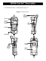
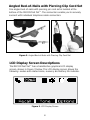
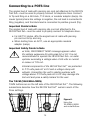
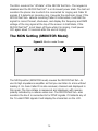
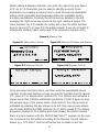
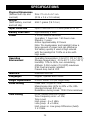
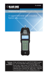
1
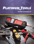
The first true 21st century telecommunication line analyzer.
User Manual
• Multilingual (English, French, Spanish)
• Rugged water and rainproof housing
• Angled bed-of-nails and Piercing
clip cord set
• Large backlit LCD
• Glow in the dark keypad
• On-hook voltage and off-hook
current readings
• Caller ID/Call Waiting Caller ID
and error detection
• Last number called or
received list
• Amplified line monitoring
• Soft key menu system
• Data Defender™ keeps
digital lines safe
• Detects and identifies
DSL and T1 lines
• DTMF Digit Capturing
• Displays Ring Frequency
& Ring Voltage
We Make Connections EZ!
IS T62
www.platinumtools.com
Table of Contents
About this Manual..................................................................................... 3
Introduction......................................................................................... 3
Symbols and Icons............................................................................... 3
Terms and Descriptions........................................................................ 4
Safety Information................................................................................ 5
Design Features........................................................................................ 6
RECON™ Test Set Description.................................................................... 7
Angled Bed-of-Nails with piercing cord set............................................ 8
LCD Display Screen.............................................................................. 8
Memory Storage................................................................................ 10
Detection Warnings............................................................................ 11
Keypad.............................................................................................. 12
Operations.............................................................................................. 14
Turning the Unit On/Off....................................................................... 14
Automatic Power Down...................................................................... 14
POTS General Guidelines.................................................................... 15
Operation Notes................................................................................. 15
Talk/Bell/Monitor................................................................................ 15
Talk Setting (Talk Mode)...................................................................... 16
Off-Hook Protection (Data Defender™)........................................... 16
Call Waiting/Caller ID.................................................................... 17
Speed Dial................................................................................... 17
Flash........................................................................................... 17
Mute Button........................................................................................... 18
Bell Setting (Bell Mode)........................................................................... 18
Monitor Setting (Monitor Mode)................................................................ 19
Setup Menu............................................................................................ 20
Memory Dial...................................................................................... 20
Recent Call List.................................................................................. 22
Language.......................................................................................... 22
Number Format.................................................................................. 22
Ring Volume...................................................................................... 22
Display Contrast................................................................................. 22
Backlight level.................................................................................... 22
Auto Power Off................................................................................... 22
Maintenance ......................................................................................... 23
Battery Replacement.......................................................................... 23
Cleaning............................................................................................ 23
Storage............................................................................................. 24
Customer Service.................................................................................... 24
Contacting Platinum Tools................................................................... 24
Additional Accessories . ..................................................................... 24
Warranty Information.......................................................................... 25
Registration....................................................................................... 25
Disposal............................................................................................ 25
Returns............................................................................................. 25
Specifications......................................................................................... 26
2
ABOUT THIS MANUAL
The RECON Test Set™ is a self-contained, battery-powered, telephone
test set for use by installers and repair technicians. Its state of the art
design makes it rugged and water resistant. The RECON Test Set™
is ideal for temporary communication, servicing and installing
telephone & data lines. It comes with a protective silicone™ boot as
well as a deluxe cord set made from nylon cloth covered test lead wire.
Also available is an optional carrying case that holds the test set.
Symbols & Icons
The following symbols are used throughout the manual or in the
display screen of the RECON Test Set™ to help you avoid personal
injury and potential damage to the test equipment (Table 1).
Table 1. Symbols and Icons
Symbol !
Definition
Warning: Potential for personal injury
Caution: Potential for damage to or destruction
of equipment
Conformité Européenne: Conforms with European
Economic Area directives
Disposal information: Do not place equipment
and/or its accessories in the trash. Items must
be properly disposed of in accordance with local
regulations
3
Terms and Descriptions
Table 2 defines the terms used throughout the manual and provides
information to assist you with proper operation and understanding of
the unit and its functions.
Table 2. Terms and Descriptions
Terms Description and Uses
Talk Mode
In this mode, the RECON Test Set™ goes “off hook” and produces a dial tone when connected to a POTS line. While
off-hook, the RECON Test Set™ can dial phone numbers from
its keypad or via internal memory slots.
Bell Mode
This is the “on hook” or “off” mode. In this mode, caller ID
and the Ringer are activated when a call is being received.
Monitor
Mode
Monitor mode allows listening to a line without loading it.
It displays line voltage, on-hook Caller ID and any detected
DTMF digits on the line.
POTS line
“Plain Old Telephone Service” the basic form of wired
residential and small business service connection.
Hook flash
Rapid depression and release of the switch hook which is
used for placing a call on hold, notifying an operator of the
completion of a call, or signaling a PBX.
DTMF
Dual Tone Multi-Frequency is the signaling between the
subscriber and switching equipment from push button
telephones.
Tone
Tone dialing mode uses the DTMF method to signal the
switching equipment for each numbered button press.
Pulse
Pulse dialing mode signals the central office or switch by
opening and closing the telephone loop a specific amount of
times depending on the number dialed.
CID and
CWCID
Caller ID is 1200 BAUD modem data sent between the first
and second ring with information about the incoming call for
display on a phone that recognizes CID. Call Waiting Caller
ID is the same information sent to the phone while a call is
in progress preceded by a call waiting tone.
Tip and
Ring
Tip and Ring are the historical names for the two leads of a
POTS line. Tip is the black lead and Ring the red lead of the
cord set. Contrary to modern standards, the black lead is a
positive voltage with respect to the red lead.
4
Safety Information
To ensure safe operation of the RECON Test Set™, follow the instructions
carefully and observe the warning and caution messages listed in
Table 3. Failure to observe warnings can result in damage to the unit.
Table 3. Safety Information
Notification
Definition
xxV TOO HIGH
DISCONNECT NOW!
High Voltage detection appears when the voltage on the cable is unsafe and exceeds 65 volts peak
AC or DC.
5
DESIGN FEATURES
• Largest backlit LCD display on the market
• Ergonomically designed body for comfortable use
• Rainproof and highly water/dust resistant case to IP54 standard
• Drop tested up to 20 ft
• 60 inch Angled Bed-of-Nails with Piercing pin cord set
• Glow-in-the-dark keypad
• Metal spring-loaded belt clip
• Loud speaker with fine volume adjustment
• Adjustable earpiece volume, hearing aid compatible
• Microphone mute with toggle on/off locking feature
• Soft key menu system simplifies user interface and customization
• Contact list of up to 8 names and phone numbers
• Supports three languages: English, Spanish and French
• Measures and displays ring frequency and voltage
• Supports both CID and CWCID
• Cushion boot for extra protection in ultra-harsh environments
• Data Defender™ detects lines with data – DSL, T1, etc. (Data
Defender is a trademark of Independent Technologies)
• High line voltage protection with override options
• Active monitor circuitry minimizes load on subscriber line
• DigitView™, DTMF digit detection and display in Monitor mode,
diagnose premise equipment
• PwrSave™ circuitry for Extra Long battery life
6
RECON Test Set™ Description
The RECON Test Set™ is illustrated in Figure 1.
Figure 1. RECON Test Set™
Metal
Spring-Loaded
Belt Clip
Receiver
Graphical
LCD
Screen
Mute
Button
Keypad
Microphone
Loud
Speaker
Talk, Bell,
Monitor
Buttons
Battery
Door
7
Angled Bed-of-Nails with Piercing Clip Cord Set
One angled bed-of-nails with piercing pin cord set is located at the
bottom of the RECON Test Set™. The connectors enable you to securely
connect with individual telephone cable connectors.
Figure 2. Angled Bed-of-Nails with Piercing Clip Cord Set
LCD Display Screen Descriptions
The RECON Test Set™ has a transflective graphical LCD display
screen, shown in Figure 3 below. The LCD display screen shows the
following: modes and related icons, memory and battery life indicator.
Figure 3. LCD Display Screen
8
Talk Mode
When the Talk button is pressed, the RECON Test Set™ goes off
hook and displays the line condition on the LCD display screen.
The following information is displayed on the screen when
RECON Test Set™ goes off hook:
• mA - The loop current measured on the line, normal polarity
and reverse polarity
• Telephone Icon - Indicates that the RECON Test Set™ is operating in Talk Mode
• Tone/Pulse Icon - Displays whether the RECON Test Set™ is in
DTMF tone or pulse dial mode
• Speaker Icon - Appears when the loudspeaker is active
• Microphone Icon - Indicates if the microphone is muted or
unmuted
• Battery Icon - Displays remaining battery life. A new set of batteries
has four bars
• Recall Soft Key - Press F1 to go to the Speed Dial screen.
• Tone Soft Key - Press F2 to toggle between tone and pulse dialing.
• Option Soft Key - Press F3 to activate a popup menu for dialing
A-D and Pause.
9
Memory Storage
While in the Setup menu, numbers 1-8 will be displayed representing the
8 name and number memory locations. By selecting a memory location
number you will be able to edit or erase an entry. See Table 5 for a
description of the display screen updates when Memory Storage is in use.
Table 4. Memory Storage
Values
Description
12345678
The unit has eight memory storage locations.
The slot number is reverse video if in use.
Memory Dial
Each memory slot has the option to view or enter
a name and number.
Memory Name
Up to 16 characters can be entered to identify
the number stored in that location.
Memory Number
Up to 32 digits can be saved in each of the
8 memory locations.
Note: Refer to the Using Memory Storage section on page 17 to
learn how to store multiple number values for testing purposes.
Battery Life Indicator (
)
The battery life icon appears in the upper right corner of the LCD
display screen to demonstrate the approximate remaining battery life.
A new set of batteries shows four bars. The number of bars decreases
as the battery is nearing depletion. At about 4.2 volts the battery icon
has no bars. At about 3.5 volts the screen starts to fade. Results may
be unreliable at this point.
Note: The RECON Test Set™ will turn off if the power supply goes
out of regulation from a low battery condition.
10
Detection Warnings
When entering Talk mode the RECON Test Set™ performs several tests
before going off-hook. These tests include high and low voltage checks
and data detection. The following describes the types of warning
screens that might be encountered.
Figure 4.1 - The voltage warning display screen is presented if the
voltage detected on a cable exceeds 65 volts peak AC or DC. If this
screen appears, the RECON Test Set™ disconnects from the line and
retries every few seconds. The RECON Test Set™ should be disconnected immediately from the source of voltage to prevent damage.
Figure 4.2 - The high current warning is displayed if the current on
the line exceeds 125mA. If this screen appears, the RECON Test Set™
should be disconnected immediately from the source of the current.
Figure 4.3 - If a line is in use, the RECON Test Set™ will display the
line in use screen. To connect, press the F2 soft key.
Figure 4.4 - If data is found, the Data Present warning is displayed
with the measured KHz.
Figure 4. Detection Warning Screens
Figure 4.1 Over Voltage Warning
Figure 4.2 Over Current Detection Warning
Figure 4.3 Line In Use Warning
Figure 4.4 Data Present Warning
Note: The RECON Test Set™ continually checks for the presence
of voltage on a connected cable.
11
Keypad
The RECON Test Set™ is equipped with a glow in the dark keypad. There
are seven control buttons illustrated in Figure 5. Three buttons, appearing
on the top row of the keypad, are used with the corresponding menu
option displayed on the LCD screen. A Setup button will access the setup
menu in Monitor or Talk modes. The Up/Left, Down/Right buttons are
used to scroll through menu options or adjust the volume. The speaker
button activates the RECON Test Set’s™ loudspeaker. The twelve digit
telephone keypad is used to dial a number or send DTMF tones. The
button functions are explained in Table 5.
Figure 5. Keypad and Control Buttons
The F1, F2, and F3 keys select the option
represented on the screen above it.
Setup
button
Speaker
button
Up/Left
arrow button
Down/Right
arrow button
12 digit
DTMF
buttons
12
Table 5. Keypad
Button
Function
Talk
• The Talk button is used to power on the RECON Test Set™ and goes “Off Hook” if appropriate line voltage is detected.
• While in talk mode, the Talk button can be pressed to
“Flash” the line.
• The Setup menu is accessible in Talk mode.
Bell
• Pressing the Bell mode button will power off the
RECON Test Set™.
• Goes “on-hook” if RECON Test Set™ was in Talk mode.
• Bell mode is used for caller ID and the incoming
call ringer.
Monitor
• Monitor mode is used to listen for line condition and
measure line voltages.
• DTMF digits are captured and displayed.
• The setup menu is accessible in Monitor mode.
F1/F2/F3
• F1, F2, and F3 correspond to the options displayed on
the LCD screen directly above them.
Up/Left
• In Talk and Monitor mode, these buttons are used to
Down/Right adjust the volume.
Arrows
• In the Setup mode, these buttons are used to scroll
though options, delete an entry, or add a space.
Speaker
• The Speaker button activates the loudspeaker on the
back of the RECON Test Set™ and mutes the microphone.
• Hold the Speaker button down for 2 seconds to toggle
the backlight on/off.
Mute
• The Mute button silences the microphone while in
Talk mode.
• When the loudspeaker is on, the mute button will mute
the loudspeaker and activate the microphone, a push to
talk function.
• In Monitor mode, hold the Mute button down to mute the
loudspeaker.
Setup
• The Setup button will display the setup menu in Monitor
or Talk mode.
13
OPERATIONS
To ensure safe operation of the RECON Test Set™, follow the instructions
carefully and pay attention to the warning and caution symbols. Failure
to observe warnings can result in severe injury or death and can
damage the unit.
Turning the Unit On/Off
Turn Unit On
• Press the Talk or Monitor mode buttons on the side of the RECON Test Set™. The RECON Test Set™ immediately measures voltage (monitor mode) or current (talk mode) when powered ON.
Turn Unit Off
• Press the Bell mode button to power off the RECON Test Set™.
The “T3 Innovation” screen will be displayed for 10 seconds
before unit is fully powered off.
Automatic Power Down
The RECON Test Set™ has automatic power-off for all modes to
conserve the battery. The default power-off time is set for 20 minutes
of no activity. To change the automatic power-off, refer to page 18 in
the Setup Mode portion of the instruction manual. To “wake up” the
test set when RECON Test Set™ has timed out and powered OFF,
press the TALK or MON button.
POTS Testing General Guidelines
The RECON Test Set™ is intended for temporary connection for
servicing phone lines.
14
Connecting to a POTS line
The angled bed of nails with piercing pin cord set attached to the RECON
Test Set™ must be used to properly connect to telephone lines. Connect
to Tip and Ring on a 66 block, 110 block, or modular adaptor (banjo). Because typical phone line voltage is negative, the red lead is connected to
Ring (negative), and the black lead is connected to positive ground (Tip).
Important Points to Note
The angled bed of nails with piercing clip cord set attached to the
RECON Test Set™ must be used to properly connect to telephone lines.
• For 66/110 blocks, affix the angled bed-of-nails with piercing
pin cord set to tip and ring.
• When testing from an RJ11, use an appropriate modular
adaptor (banjo).
Important Safety Points to Note
xx Volts, DISCONNECT NOW! message appears when
the voltage surpasses 65 volts peak AC or DC. It is not
recommended to operate the RECON Test Set™ on cable
systems exceeding a voltage value of 65 volts or current
in excess of 125 mA.
!
!
Internal components of the RECON Test Set™ are protected to 270 volts peak AC or DC and a voltage clamp will
activate. Connecting the unit to cabling systems with
voltage above 270 volts peak AC or DC may damage the
test unit and pose a safety hazard for the user.
The T/B/M (TALK/BELL/MON)
T/B/M buttons are on the left side of the RECON Test Set™. The following
subsections describe how the RECON Test Set™ works in each of the
three settings.
Figure 6.
Using the
TALK/BELL/MON
and mute Buttons.
15
The TALK Setting (TALK Mode)
The “TALK” or off-hook position takes the RECON Test Set™ “off hook” on
a standard “POTS” (plain old telephone service) voice phone line. While
the RECON Test Set™ is off-hook, it can dial numbers either directly from
the keypad or from its memory dial slots (see page 17, figures 9-4).
Off-Hook Protection
The RECON Test Set™ checks for low voltage, high voltage, and presence
of data before going off-hook. Once off-hook, the RECON Test Set™
checks for excess loop current.
• The RECON Test Set™ must measure 18 volts or more on the line
it is connected to (a voltage level indicating a live but not in use
line) before it will go off hook. If the RECON Test Set™ doesn’t go
off hook, it displays “Off-Hook Protection”, the voltage measured
for the line, and an option to “Connect” on its LCD screen. To
connect, press the F2 button under “Connect” to go off hook
despite this voltage reading and attempt to operate normally
(Because the RECON Test Set™ internal voice circuits are line
powered, it won’t work if there’s insufficient power on the line).
• The RECON Test Set™ also checks for line voltage exceeding 65
volts. If it finds the line voltage exceeds this level, it doesn’t
go off-hook but displays the messages: “xxV,TOO HIGH!” and
“DISCONNECT NOW!!” (see page 9 figure 4.1). It continues
to monitor the line voltage for about five minutes, then powers
down if the high voltage has not been removed. The RECON Test Set™ will automatically go off-hook if the voltage goes below the
65 volt threshold. The line current will be displayed on the top
line of the LCD. The RECON Test Set™ detects the polarity of the connection and will reverse-video the line current to indicate a reverse connection.
• In addition to the voltage checks when going off-hook, the RECON Test Set™ uses patented Data Defender™ technology to check
for data being present on the line. If data is detected, “Off-Hook Protection”, “Signal: xxx KHz” and “Active Data Found” are
displayed. The average signal frequency of the largest amplitude
data energy is displayed. An override soft key option, “Connect”,
is displayed and by pressing F2 the RECON Test Set™ will go
16
off-hook. The override feature may be needed should high
frequency energy be present on a circuit due to stray coupling.
The Data Defender™ circuitry is active in monitor mode and
will display signal frequency and “Active Data Found” if data
is present. Data Defender™ is a trademark of Independent
Technologies, Patent number 6,556,661.
DSL Detection
The RECON Test Set’s™ average frequency reading will be either in the
range of 70 to 90 KHz at the premise (upstream) end of an active DSL link
or 260 to 280 KHz at the DSLAM (downstream) end due to the pilot tones.
T1 Detection
The RECON Test Set™ average frequency reading will read the carrier
frequency between 700 and 800 KHz on a T1 line.
CWCID
In Talk mode the RECON Test Set™ supports Call Waiting Caller ID
(CWCID or Type 2 Caller ID). When a call is already in progress, an
incoming call’s ID is displayed on the screen. During this the label
“CWCID” replaces the line current field. The user can switch to the
incoming call by pressing the Talk button to “Flash” the line.
Speed Dial
In Talk mode, function key F1 (“Recall”) accesses a screen for speed
dialing. From the Speed Dial screen, press the zero (0) key to dial the last
number dialed or a Memory Dial slot by pressing 1 through 8. The soft
function keys provide further access to the Memory Dial slots or Recent
Call List by pressing the soft key and scrolling through the slots using the
arrow keys. Press the Dial soft key to dial the currently displayed number.
Flash
To flash the phone line, press the “T” (Talk) button while off hook.
The Flash function breaks the phone line connection for 0.6 seconds,
simulating a phone “hookflash” signal. Hookflashes are often used to
transfer calls or to activate special PABX or central-office features.
17
Volume Control
Use the and keys to adjust receiver and loudspeaker volume.
During adjustment a bar graph is displayed to show the volume percentage.
The receiver and loudspeaker have separate volume settings. Volume levels
for Talk mode and Monitor mode are set and stored independently.
Using the Multi-function Mute Button
When the test set is off hook in the TALK mode and the loudspeaker is
OFF, you can mute the RECON Test Set™ microphone by pressing down
the mute button on the right-hand side of the RECON Test Set™ (see Page
13, figure 6). If you tap the button for less than 2 seconds, the mute lock
feature is enabled and the microphone icon is in reverse video. The test
set will remain muted until you press the button again. If you hold this
button down for more than 2 seconds, the mike will be muted only while
the button is held down; as soon as you let go, it will resume operating
normally.
When the test set is off hook in the TALK mode with the loudspeaker ON,
the microphone is automatically muted to prevent feedback. The mute
button is used to turn the loudspeaker OFF and the microphone ON so that
you can talk to the remote party over the phone line. The microphone is
only ON while the mute button is being held down. Under these conditions,
when the mute button is pressed, the speaker icon is displayed in reverse
video and the microphone icon is displayed normally.
When the test set is in the Monitor mode with the loudspeaker ON, the
mute button is used to mute the loudspeaker. The loudspeaker is only OFF
while the mute button is being held down in a push to talk like operation.
While muted, the speaker icon on the screen is displayed in reverse video.
The BELL
Setting
(BELL Mode)
PLATINUM TOOLS
1-805-384-2777
Table 7.
Caller ID Screen
18
The BELL mode is the “off state” of the RECON Test Set™. The keypad is
disabled and the RECON Test Set™ is in its lowest power state. The test set
monitors the phone line to which it is connected for ringing and Caller ID
signals. If it detects an incoming ring, it sounds the electronic ringer. If the
RECON Test Set™ detects incoming Caller ID information, it will test the
signal for correct format, checksum, and display the frequency and RMS
voltage of the ring signal at the top of the screen. In Bell Mode, if the
RECON Test Set™ is not taken off hook while it is ringing, it will power
OFF again about 10 seconds after the end of ringing.
The MON Setting (MONITOR Mode)
Figure 8. Monitor mode Screen
The MON position (MONITOR mode) causes the RECON Test Set™ to
use its high impedance amplifier so that you can listen to a line without
loading it. On-hook Caller ID is also received, checked and displayed in
this mode. The line voltage is measured and displayed, with reverse
polarity indicated by a reverse video icon. The RECON Test Set™ also
monitors the line it is connected to for DTMF signals. If it detects any of
the 16 valid DTMF signals it will display the characters on the LCD.
19
• Headset Icon - Indicates that the RECON Test Set™ is in
Monitor Mode
• xxV - The voltage measured on the line, normal and
reverse polarity
• Speaker Icon - Appears when the loudspeaker on the back is
active
• Battery Icon - Displays remaining battery life. A new set of
batteries has four bars
When the test set is in the Monitor mode with the loudspeaker ON, the
mute button is used to mute the loudspeaker. The loudspeaker is only OFF
while the mute button is being held down. While muted, the speaker icon
on the screen is displayed in reverse video.
Volume Control
Use the and keys to adjust receiver and loudspeaker volume. During
adjustment a bar graph is displayed to show the volume percentage. Volume
levels for Talk mode and Monitor mode are set and stored independently.
Setup Menu
To enter the Setup Menu, the phone must be in talk or monitor mode (not
Off Hook Protection mode). By pressing the Setup key, the RECON Test Set™
will present a list of options that can be modified. The RECON Test Set™
command keys now take on their setup-mode functions/identities. You
can use the or scroll keys to move to different items. Pressing
the Setup key will exit the setup menu.
Setup mode automatically exits after 2 minutes without a key press.
Memory Dial - The Memory Dial entry displays the eight memory dial
records that are available (see figure 9). The digits in reverse video
identify slots that are not empty. Press a numeric key to jump immediately
to that slot. Alternately, press function key F3 to access slot #1 of the
Memory Dial list.
In the Memory Dial list, use the arrow keys to move up and down between
entries. Function key F3 opens the entry for editing and function key F1
deletes (clears) an entry (see figure 9.2). When in Talk mode, function key
F2 (Call) dials the currently displayed number.
20
When editing a Memory Dial slot, you enter the name first (see figure
9.3). Up to 16 characters can be used to identify a record. Enter
characters by pressing a numeric key to cycle through its associated
letters. Both uppercase and lowercase letters are available via the
scrolling mechanism. Pressing the left arrow key deletes to the left,
pressing the right arrow key moves to the right, adding a space. The
Clear function key (F2) deletes the entire entry. Use the other function
keys to cancel (F1) or save (F3) the edited results. If you do not want to
change the existing name, just press F3 to proceed to number entry.
Figure 9. Memory Dial
Figure 9.1 Setup Menu Screen
Figure 9.2 Memory Dial Name and Number
Figure 9.3 Memory Dial Edit
Figure 9.4 Number Dial Edit
Once you save the slot’s name, you then enter the associated phone
number. On the Edit Number screen you use the function keys to cancel
(F1), save (F2) or access other options (F3). The Options key activates a
popup menu that contains additional operations. Press F3 again to view
the second page of the popup menu. Each item on the popup menu is
activated by pressing the key shown to its left. The popup menu allows
you to enter additional DTMF numbers (A-D), add a pause to the dialing
sequence, change to tone dialing and clear (erase) the phone number.
Enter a phone number with the RECON Test Set’s™ keypad. As the number is entered it is formatted according to the Number Format defined
below (e.g. 123-4567). Use the left arrow key to delete to the left..
21
Recent Call List - The RECON Test Set™ automatically stores the last
10 numbers called or received. To view the list, press F3 (View) while
Recent Call is displayed in Setup. Scroll through the list of recent calls with
the and keys. Press the Setup key to exit. Use function key F1 (Del) to
delete an entry from the list and function key F3 (Save) to save an entry
in the Memory Dial list.
Language - Use function keys F1 and F3 to switch between English,
French and Spanish.
Number Format - This entry defines how telephone numbers are
displayed. Use function key F3 to edit the numeric formatting. When
editing, use the pound key (#) to enter a digit placeholder and the one
key (1) to scroll through a short list of symbols (minus, plus, parenthesis,
period, forward slash). The zero key (0) enters a space. The and
scroll keys delete left or move right during editing. Use the function keys
to Cancel, Clear or Save the edited format.
Ring Volume - The Ring volume can be adjusted by pressing F1
(decrease) and F3 (increase). The RECON Test Set™ will sound an audible
ring relative to the volume setting. To repeat the ring, you can press
F2 (Ring).
Display Contrast -The display contrast can be adjusted from 40%
to 70% using the F1 button (decrease) and F3 (increase). The contrast
immediately adjusts to the specified level.
Backlight Level - The backlight can be adjusted from 0% to 100% using
the F1 button (decrease) and F3 (increase). The backlight immediately
adjusts to the specified level. Note that higher backlight levels drain the
battery more quickly. The backlight is turned on and off at any time by
pressing and holding the speaker key for 2 seconds.
Auto Power off - The auto power off can be adjusted from 10 minutes
up to 60 minutes or off (Never) using the F1 button (decrease) and F3
(increase and off). This controls how long the phone remains in Talk or
Monitor mode, with no activity, before returning to Bell mode.
22
Maintenance
Battery Replacement
!
Disconnect RECON Test Set™ test leads prior to opening battery door to avoid electrical shock and personal injury.
1. Carefully remove silicone™ boot from RECON Test Set™.
Watch Video How to Remove Boot from Phone
www.platinumtools.com/recon/remove-boot
2. Remove all 4 screws on the battery door, located in the back
of the RECON Test Set™ towards the bottom of the unit, with a #1 Philips head screwdriver.
3. Take off the battery door and remove old batteries.
4. Replace with four AAA Alkaline batteries. Slide batteries into
the battery cartridge according to the diagram imprinted on
the bottom of the battery compartment.
5. Return the battery door to the unit and tighten the screw to
secure the battery door. The door is keyed to fit in only one
direction.
6. Carefully replace silicone™ boot on RECON Test Set™.
!
Disconnect RECON Test Set ™ test leads prior to opening battery door to avoid electrical shock and personal injury.
Cleaning
Use a damp, clean cloth to clean the tester.
!
Disconnect the RECON Test Set ™ test leads prior to cleaning. Failing to do so can damage the unit and result in personal injury.
Do not use abrasive harsh cleaners, or solvents to clean the
RECON Test Set ™.
23
Storage
When the RECON Test Set™ is not in use, store in a dry, protective
case. The batteries should be removed if the unit is stored for a long
period of time.
Do not expose the RECON Test Set™ to high temperatures or humidity.
When stored in temperatures exceeding the limits listed in the
Specifications section, allow the RECON Test Set™ to return to the
normal, recommended operating conditions prior to use.
Additional Accessories
The list of accessories below (see Table 6) will assist you with operating
the RECON Test Set™. These items are available for purchase through
Platinum Tools authorized distributors.
Table 6. Additional Accessories
Accessory
Product # Description
4007
Hanging Pouch
CUSTOMER SERVICE
Contacting Platinum Tools:
For technical information and customer support, please visit
www.platinumtools.com or send an email to
[email protected]
Contact Numbers:
Address:
Phone: 805-384-2777
Fax: 805-384-2778
806 Calle Plano
Camarillo, CA 93012
24
Warranty Information
Platinum Tools guarantees that its products will be free of all defects
in material and workmanship. This warranty extends for a period of
18 months for the Platinum Tools test equipment from the date of
manufacture or proof-of-purchase.
All products deemed defective under this warranty will be repaired or
replaced at Platinum Tools’ discretion. No further warranties either
implied or expressed will apply, nor will responsibility for operation of this
device be assumed by Platinum Tools.
Product Registration
Registration of your purchased equipment and accessories allows you
to access support information, receive notifications of product updates,
and to validate your warranty. Please visit the Platinum Tools website at
www.platinumtools.com/warranty to register products.
Disposal
WEEE Compliant: Prior to disposal of this product, please contact Platinum Tools for proper disposal
options.
Returns
Prior to returning any product to Platinum Tools, you must first request
a Return Merchandise Authorization Number by contacting the
Customer Service Department at 805-384-2777.
Note: Shipments will not be accepted without this number,
which must be clearly marked on the shipping label.
1.Prior to packing, include a copy of the sales receipt if available.
2.Provide a description of the operational problem with the product(s)
being returned.
3.Include a contact name, phone number, and e-mail address.
4.Pack items securely to prevent damage during shipping.
5.Ship prepaid to: Platinum Tools
25
806 Calle Plano
Camarillo, CA 93012
SPECIFICATIONS
Physical Dimensions
(Without belt clip and Size: 21 x 6.4 x 5.1 cm
cord set)
(8.25 x 2.5 x 2.0 inches)
Weight
(With battery, cord set
and belt clip)
559.7 grams (19.74 oz.)
Input Protection
Input Protection To 270 volts peak AC or DC
Battery Low Level
Approximately 4 volts
Power
4 x AAA alkaline batteries
Operation: 7 hours min. 150 hours max.
Standby: 2 years
Active: approximately 43 hours
Note: The loudspeaker and backlight draw a
large amount of power and can discharge the battery quickly if used at high volume with the backlight at 100% on a line with high audio.
Operating Environment
Operating temperature: 0 to 50°C (32 to 122°F)
Storage temperature: -20 to 60°C (-4 to 140°F)
Humidity: 10% to 90%, non-condensing
Altitude: 3,050 meters (10,000ft) maximum
IP54 Dust and water resistant
Passed drop test at 20ft
Interface Attached cord set
Languages English, Spanish and French
Ringer Equivalence In BELL mode: 0.0 (no ringer load)
Pulse Dialing Pulse rate: 10 pps ± 10%;
Make/break ratio: 60% to 40% ±2%; USA
Interdigit interval: 820 ms;
Resistance during break: 120K Ohms minimum
Tone Dialing DTMF output (into 600 Ohms):
Tone-frequency error: ±1.5%;
Tone Level:
High group: -6 ±2 dBm;
Low group: -8 ±2 dBm;
High group vs. Low group Difference (twist):
2 ±1 dBm
26
SPECIFICATIONS
Flash Duration
600 ±50 ms
Pause Duration
Tone: 3 seconds; Pulse: 3.4 seconds
Memory
8 programmable locations, 32 digits with 16
character tag, stored in non-volatile memory
Last number redial plus list of last 10 numbers
dialed or received
Return Loss
Minimum 14 dB at 600 Ohms
Line-Current Range
10 to 110 mA
Apparent Line Resistance
275 Ohms at 20 mA
Compliance Complies with Conformité
Européenne directives.
27