1
Software Tutorial
Biomek 4000
Laboratory Automation Workstation
PN A99502AA
October 2012
Beckman Coulter, Inc.
250 S. Kraemer Blvd.
Brea, CA 92821
Biomek 4000 Software Tutorial
PN A99502AA (October 2012)
Copyright © 2012 Beckman Coulter, Inc.
All rights reserved.
Trademarks
BECKMAN COULTER, the stylized logo and Biomek are
trademarks of Beckman Coulter, Inc., and are registered
with the USPTO.
All other trademarks, service marks, products, or services
are trademarks or registered trademarks of their
respective holders.
Find us on the World Wide Web at:
www.beckmancoulter.com
Made in USA
Revision History
This document applies to the latest software listed and higher versions. When a subsequent software
version changes the information in this document, a new issue will be released.
Initial Issue, 10/12
Software version 4.0
PN A99502AA
iii
Safety Notice
Overview
Read all product manuals and consult with Beckman Coulter-trained personnel before attempting
to operate the instrument. Do not attempt to perform any procedure before carefully reading all
instructions. Always follow product labeling and manufacturer’s recommendations. If in doubt as
to how to proceed in any situation, contact your Beckman Coulter Representative.
Beckman Coulter, Inc. urges its customers and employees to comply with all national health and
safety standards such as the use of barrier protection. This may include, but is not limited to,
protective eyewear, gloves, and suitable laboratory attire when operating or maintaining this or
any other automated laboratory instrumentation.
WARNING
If the equipment is used in a manner not specified by Beckman Coulter, Inc., the
protection provided by the equipment may be impaired.
Alerts for Warning, Caution, Important, and Note
All Warnings and Cautions in this document include an exclamation point, framed within a triangle.
The exclamation point symbol is an international symbol which serves as a reminder that all safety
instructions should be read and understood before installation, use, maintenance, and servicing are
attempted.
WARNING
WARNING indicates a potentially hazardous situation which, if not avoided, could
result in death or serious injury.
CAUTION
CAUTION indicates a potentially hazardous situation, which, if not avoided, may
result in minor or moderate injury. It may also be used to alert against unsafe
practices.
IMPORTANT IMPORTANT is used for comments that add value to the step or procedure being performed.
Following the advice in the Important adds benefit to the performance of a piece of equipment or to a
process.
NOTE NOTE is used to call attention to notable information that should be followed during installation, use,
or servicing of this equipment.
PN A99502AA
v
Safety Notice
Instrument Safety Precautions
Instrument Safety Precautions
WARNING
Risk of operator injury if:
• All doors, covers and panels are not closed and secured in place prior to and
during instrument operation.
• The integrity of safety interlocks and sensors is compromised.
• You contact moving parts.
• You mishandle broken parts.
• Doors, covers and panels are not opened, closed, removed and/or replaced
with care.
• Improper tools are used for troubleshooting.
To avoid injury:
• Keep doors, covers and panels closed and secured in place while the
instrument is in use.
• Take full advantage of the safety features of the instrument. Do not defeat
safety interlocks and sensors.
• Acknowledge and act upon instrument alarms and error messages.
• Keep away from moving parts.
• Report any broken parts to your Beckman Coulter Representative.
• Use the proper tools when troubleshooting.
CAUTION
System integrity could be compromised and operational failures could occur if:
• This equipment is used in a manner other than specified. Operate the
instrument as instructed in the Product Manuals.
• You introduce software that is not authorized by Beckman Coulter into your
computer. Only operate your system’s computer with software authorized by
Beckman Coulter.
• You install software that is not an original copyrighted version. Only use
software that is an original copyrighted version to prevent virus
contamination.
vi
PN A99502AA
Safety Notice
Electrical Safety
CAUTION
If you purchased this product from anyone other than Beckman Coulter or an
authorized Beckman Coulter distributor, and, if it is not presently under a
Beckman Coulter Service Maintenance Agreement, Beckman Coulter cannot
guarantee that the product is fitted with the most current mandatory engineering
revisions or that you will receive the most current information bulletins
concerning the product. If you purchased this product from a third party and
would like further information concerning this topic, contact your Beckman
Coulter Representative.
Electrical Safety
To prevent electrically related injuries and property damage, properly inspect all electrical
equipment prior to use and immediately report any electrical deficiencies. Contact a Beckman
Coulter Representative for any servicing of equipment requiring the removal of covers or panels.
High Voltage
This symbol indicates the potential of an electrical shock hazard existing from a high-voltage
source and that all safety instructions should be read and understood before proceeding with the
installation, maintenance, and servicing of all modules.
Do not remove system covers. To avoid electrical shock, use supplied power cords only and connect
to properly grounded (three-holed) outlets.
Laser Light
This symbol indicates that a potential hazard to personal safety exists from a laser source. When
this symbol is displayed in this manual, pay special attention to the specific safety information
associated with the symbol.
Laser Specifications
• Laser Type: Class II Laser Diode
• Maximum Output: 11 mW
• Wavelength: 670 nm
PN A99502AA
vii
Safety Notice
Chemical and Biological Safety
Disposal of Electronic Equipment
It is important to understand and follow all laws regarding the safe and proper disposal of electrical
instrumentation.
The symbol of a crossed-out wheeled bin on the product is required in accordance with the Waste
Electrical and Electronic Equipment (WEEE) Directive of the European Union. The presence of this
marking on the product indicates:
• That the device was put on the European Market after August 13, 2005 and
• That the device is not to be disposed via the municipal waste collection system of any member
state of the European Union.
For products under the requirement of WEEE directive, please contact your dealer or local Beckman
Coulter office for the proper decontamination information and take back program which will
facilitate the proper collection, treatment, recovery, recycling, and safe disposal of device.
Chemical and Biological Safety
If a hazardous substance such as blood is spilled onto the instrument, ALPs, or accessories, clean up
the spill by using a 10% bleach solution, or use your laboratory decontamination solution. Then
follow your laboratory procedure for disposal of hazardous materials. If the instrument, ALPs, or
accessories need to be decontaminated, contact your Beckman Coulter Representative.
WARNING
Risk of chemical injury from bleach. To avoid contact with the bleach, use barrier
protection, including protective eyewear, gloves, and suitable laboratory attire.
Refer to the Safety Data Sheet for details about chemical exposure before using
the chemical.
viii
PN A99502AA
Safety Notice
Chemical and Biological Safety
WARNING
Before running with chemistry or any biological samples, new labware types will
require testing to determine if labware offsets are necessary to move to or from
the Peltier ALP, or to access the labware during pipetting operations while on the
Peltier ALP. If you do not do the required testing, the labware could crash and the
contents could spill if the offset is incorrect.
Normal operation of the instrument may involve the use of materials that are
toxic, flammable, or otherwise biologically harmful. When using such materials,
observe the following precautions:
• Handle infectious samples according to good laboratory procedures and
methods to prevent the spread of disease.
• Observe all cautionary information printed on the original solutions’
containers prior to their use.
• Dispose of all waste solutions according to your facility’s waste disposal
procedures.
• Operate the instrument in accordance with the instructions outlined in this
manual and take all the necessary precautions when using pathological, toxic,
or radioactive materials.
• Splashing of liquids may occur; therefore, take appropriate safety
precautions, such as using safety glasses and wearing protective clothing,
when working with potentially hazardous liquids.
• Use an appropriately-contained environment when using hazardous
materials.
• Observe the appropriate cautionary procedures as defined by your safety
officer when using flammable solvents in or near a powered-up instrument.
• Observe the appropriate cautionary procedures as defined by your safety
officer when using toxic, pathological, or radioactive materials.
NOTE Observe all warnings and cautions listed for any external devices attached or used during operation
of the instrument. Refer to applicable external device user’s manuals for operating procedures of that
device.
NOTE For Safety Data Sheets (SDS/MSDS) information, go to the Beckman Coulter website at
www.beckmancoulter.com.
PN A99502AA
ix
Safety Notice
Moving Parts
Moving Parts
WARNING
Risk of personal injury. To avoid injury due to moving parts, observe the following:
• Never attempt to exchange labware, reagents, or tools while the instrument
is operating.
• Never attempt to physically restrict any of the moving components of the
instrument.
• Keep the instrument work area clear to prevent obstruction of the movement.
Cleaning
Observe the cleaning procedures outlined in this user’s manual for the instrument. Prior to cleaning
equipment that has been exposed to hazardous material:
• Contact the appropriate Chemical and Biological Safety personnel.
• Review the Chemical and Biological Safety information in the user’s manual.
Maintenance
Perform only the maintenance described in this manual. Maintenance other than that specified in
this manual should be performed only by service engineers.
IMPORTANT It is your responsibility to decontaminate components of the instrument before requesting
service by a Beckman Coulter Representative or returning parts to Beckman Coulter for repair. Beckman
Coulter will NOT accept any items which have not been decontaminated where it is appropriate to do so.
If any parts are returned, they must be enclosed in a sealed plastic bag stating that the contents are safe
to handle and are not contaminated.
x
PN A99502AA
Safety Notice
RoHS Notice
RoHS Notice
These labels and materials declaration table (the Table of Hazardous Substance's Name and
Concentration) are to meet People’s Republic of China Electronic Industry Standard SJ/T11364-2006
“Marking for Control of Pollution Caused by Electronic Information Products” requirements.
China RoHS Caution Label
This logo indicates that this electronic information product contains certain toxic or hazardous
substances or elements, and can be used safely during its environmental protection use period. The
number in the middle of the logo indicates the environmental protection use period for the
product. The outer circle indicates that the product can be recycled. The logo also signifies that the
product should be recycled immediately after its environmental protection use period has expired.
The date on the label indicates the date of manufacture.
China RoHS Environmental Label
This logo indicates that the product does not contain any toxic or hazardous substances or
elements. The "e" stands for electrical, electronic and environmental electronic information
products. This logo indicates that this electronic information product does not contain any toxic or
hazardous substances or elements, and is green and environmental. The outer circle indicates that
the product can be recycled. The logo also signifies that the product can be recycled after being
discarded, and should not be casually discarded.
PN A99502AA
xi
Contents
Revision History, iii
Safety Notice, v
Overview, v
Alerts for Warning, Caution, Important, and Note, v
Instrument Safety Precautions, vi
Electrical Safety, vii
High Voltage, vii
Laser Light, vii
Disposal of Electronic Equipment, viii
Chemical and Biological Safety, viii
Moving Parts, x
Cleaning, x
Maintenance, x
RoHS Notice, xi
China RoHS Caution Label, xi
China RoHS Environmental Label, xi
Introduction, xx
Biomek Software, xx
Using This Tutorial, xx
CHAPTER 1:
Getting Started, 1-1
What You’ll Learn In This Chapter, 1-1
Launching Biomek Software, 1-1
Viewing the Main Editor, 1-2
Beginning a Method, 1-2
Introducing Project Files, 1-3
Adding Tools to Biomek Software, 1-4
Creating a New Method, 1-4
Understanding the Start and Finish Steps, 1-6
xii
Contents
Setting Up the Deck, 1-6
Ensuring the Deck in Biomek Software is Correct, 1-6
Creating a New Deck, 1-7
Configuring the Instrument Setup Step, 1-9
Transferring Liquid, 1-14
Configuring Tip Handling, 1-15
Configuring Source Labware, 1-17
Configuring Destination Labware, 1-18
Determining the Estimated Time of Completion (ETC) of the
Method, 1-20
Running the Method, 1-22
Validating the Method and Confirming the Deck Setup, 1-22
Viewing the Method in the Biomek Simulator, 1-23
Saving a Method, 1-25
CHAPTER 2:
Using More Steps in a Method, 2-1
Introduction to Using More Steps in a Method, 2-1
What You'll Learn in This Chapter, 2-1
Setting Up Your Deck for This Chapter, 2-2
Transferring Liquid from Multiple Sources to a Single Destination, 2-3
Configuring Tip Handling, 2-4
Configuring Source Labware, 2-5
Configuring Destination Labware, 2-6
Mixing Contents in Labware, 2-7
Configuring “Mix after dispensing liquid”, 2-9
Moving Labware Around the Deck, 2-10
Moving Labware Using the Gripper Tool, 2-10
Adding Labware During a Method Run, 2-12
Moving the Pod to a New Location, 2-12
Displaying the Intermediate Step Palette, 2-13
Configuring the Move Pod Step, 2-14
Pausing the Instrument, 2-15
Configuring the Pause Step, 2-15
Adding a Second Instrument Setup Step, 2-17
Adding Labware to the Deck, 2-18
Using a Group Step, 2-20
Configuring the Group Step, 2-20
Performing Multiple Dilutions of a Sample, 2-23
Responding to an Error Message, 2-26
Locating the Error, 2-26
Correcting the Error, 2-27
Performing Single Operations With the Biomek 4000 Laboratory Automation
Workstation, 2-27
xiii
Contents
CHAPTER 3:
Using Individual Steps to Transfer Liquid, 3-1
Introduction to Using Individual Steps to Transfer Liquid, 3-1
What You’ll Learn in This Chapter, 3-1
Setting Up Your Deck for This Chapter, 3-2
Using Individual Steps to Transfer Liquid, 3-3
Load Tool Step, 3-4
Aspirating Liquid Using the Aspirate Step, 3-4
Dispensing Liquid Using the Dispense Step, 3-6
Using Variables in a Method, 3-7
Creating a Variable in the Start Step, 3-7
Using a Variable with Expressions in Step Configurations, 3-9
Changing the Value of a Variable at Run Time, 3-11
Repeating Liquid Transfer Steps Using a Loop, 3-13
Repeating Actions Using the Loop Step, 3-13
Specifying the Column to Dispense to in the Dispense Step, 3-14
Conserving Tips Using Individual Steps, 3-16
Loading and Unloading Tips Outside the Loop, 3-16
Using Lids in the Method, 3-17
Viewing Log Data, 3-20
CHAPTER 4:
Using Worklists and Conditions, 4-1
Introduction to Using Worklists and Conditions, 4-1
What You’ll Learn in This Chapter, 4-1
Setting Up Your Deck for This Chapter, 4-2
Creating a Worklist Text File, 4-3
Configuring a Worklist Text File, 4-3
Configuring a Worklist Step to Use a Worklist, 4-4
Defining and Running Procedures, 4-6
Defining a Procedure Using the Define Procedure Step, 4-6
Configuring Steps Inside the Define Procedure Step, 4-8
Loading a Tool for a Procedure, 4-8
Configuring Different Tips for Accessing Sources, 4-9
Transferring Liquid During a Procedure, 4-9
Unloading Tips During a Procedure, 4-10
Configuring the If Step to Use Conditions in a Method, 4-11
Setting Conditions Using If Steps, 4-12
Stacking Plates in a Method, 4-15
CHAPTER 5:
Using Files to Direct Transfers, 5-1
Introduction to Using Transfer From File, 5-1
What You’ll Learn in This Chapter, 5-1
Setting Up Your Deck for This Chapter, 5-1
Copying .csv Files to the Desktop, 5-3
xiv
Contents
Creating a Loop for Hit Picking, 5-3
Viewing the hits.csv File, 5-3
Inserting a Loop Step, 5-5
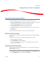
Inserting a Define Pattern Step, 5-5
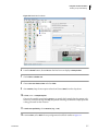
Inserting and Configuring a Transfer Step, 5-8
Inserting a Transfer From File Step for Reaction Setup, 5-11
Viewing the transferfromfile.csv File, 5-11
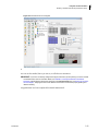
Inserting a Transfer From File Step, 5-12
Configuring Some Needed Source and Destination Information
for the Transfer From File Step, 5-14
Abbreviations
Glossary
Beckman Coulter, Inc.
Warranty and Returned Goods Requirements
Related Documents
xv
Illustrations
Illustrations
xvi
1.1
Biomek Main Editor, 1-2
1.2
Project File, 1-3
1.3
New Devices, 1-4
1.4
Main Editor When a New Method is Created, 1-5
1.5
Current Deck for This Tutorial, 1-7
1.6
Tutorial Deck Setup, 1-8
1.7
Instrument Setup Step Configuration, 1-10
1.8
InfoTip, 1-11
1.9
Labware Properties for Reservoir, 1-12
1.10
Instrument Setup Step Completed, 1-14
1.11
Transfer Step Inserted, 1-15
1.12
Tip Handling Configured and Collapsed, 1-16
1.13
Configured Source Labware, 1-18
1.14
Destination Labware Zoomed In, 1-19
1.15
Configured Destination Labware, 1-20
1.16
Finish Step Displaying the ETC, 1-21
1.17
Deck Confirmation Prompt, 1-22
1.18
Hardware Setup, 1-23
1.19
Running a Method in Simulation, 1-24
1.20
Save Method, 1-25
1.21
Method Name Has Changed, 1-26
2.1
Completed Instrument Setup Step, 2-3
2.2
Combine Step Inserted and Tip Handling Collapsed, 2-4
2.3
Source Labware for Combine Step Configured, 2-6
2.4
Stop When Finished with Sources Chosen, 2-7
2.5
Dispense Tab of the Technique Editor, 2-8
2.6
Configured Mix in a Custom Technique, 2-9
2.7
Move Labware Step Configuration, 2-11
2.8
Intermediate Step Palette Displayed, 2-13
2.9
Configured Move Pod Step, 2-14
2.10
Pause Configuration With Message Inserted, 2-16
2.11
Pause Prompt Displaying the Configured Message, 2-16
2.12
Adding an Instrument Setup Step and Toggling All Deck Positions As Is, 2-17
Illustrations
2.13
Using Clear to Remove Labware, 2-18
2.14
Configure Pod Setup, 2-19
2.15
Pod Setup Configuration, 2-20
2.16
Expanded Group Step, 2-21
2.17
Configured Group Step With Nested Steps Expanded, 2-22
2.18
Serial Dilution Step Inserted, 2-24
2.19
Error Displayed, 2-26
2.20
Single Step, 2-28
2.21
Single Step With Specific Operations Displayed, 2-28
2.22
Biomek Software Prompt, 2-29
3.1
Initial Instrument Setup for Using Individual Steps, 3-3
3.2
Source Chosen for Aspirate Step, 3-5
3.3
Aspirate Step Configured, 3-6
3.4
Vol Variable Created in the Start Step, 3-8
3.5
Volume Field, 3-10
3.6
Prompting for Value of a Variable, 3-11
3.7
Prompt to Specify the Value of a Variable, 3-12
3.8
Biomek Software Deck Setup Confirmation, 3-12
3.9
Loop Step for Repeating Aspirate and Dispense, 3-14
3.10
Text Selection, 3-15
3.11
Dispense Step Inside the Loop, 3-15
3.12
Loading and Unloading Tips Outside the Loop, 3-17
3.13
Modifying Instrument Setup Step to Add a Lid, 3-18
3.14
Using Move Labware to Remove a Lid, 3-19
3.15
Browse to Logs, 3-21
3.16
Pipetting Log, 3-22
4.1
Instrument Setup Step Configured, 4-3
4.2
Created Worklist, 4-4
4.3
Worklist Step With Text File Displayed, 4-5
4.4
Procedure Named, 4-7
4.5
Variables Entered in Define Procedure Step, 4-8
4.6
New Tips Configured, 4-9
4.7
Define Procedure Step Configured, 4-11
4.8
Condition Entered in If Step, 4-12
4.9
ReagentAddition Procedure Inserted as a Then Substep, 4-13
4.10
Variable Name and Value Changed, 4-14
4.11
Loop to Stack Plates, 4-16
4.12
Use Variables to Stack Plates, 4-17
xvii
Illustrations
xviii
5.1
Instrument Setup Step Configured, 5-3
5.2
Supplied hits.csv File, 5-4
5.3
Define Pattern Inserted Inside Loop, 5-6
5.4
Read from File Chosen, 5-7
5.5
Read From File Configured, 5-8
5.6
SamplestoTransfer Pattern Chosen, 5-9
5.7
Configured Transfer Step for Inside Loop, 5-10
5.8
Supplied transferfromfile.csv File, 5-12
5.9
Transfer From File Inserted, 5-13
5.10
Transfer From File Configured, 5-15
Tables
Tables
4.1
Values of Variables and Expressions Used in Move Labware Step
for Cycles, 4-15
xix
Introduction
Biomek Software
Welcome to Biomek Software and the Biomek 4000 Laboratory Automation Workstation.
Biomek Software controls the instrument and is designed to:
• do a substantial amount of method-building work for you.
• allow you to take as much direct and precise control over the method-building process as you
want.
The flexibility that results from this combination gives the instrument its power.
Using This Tutorial
This tutorial is designed to help you become comfortable using Biomek Software with your
instrument. The chapters in this tutorial can be completed consecutively or, depending on the
learning required, may be completed in any order. This format will allow advanced users to
complete only the chapters that include the topics they need to learn.
TIP For effective learning, print this tutorial before use, leaving your computer screen free for viewing
Biomek Software.
IMPORTANT For the tutorials to work correctly, complete all tutorials in this manual using the default
Biomek 4000 Project File, and ensure that the Default technique is used for all aspiration and dispense
activities.
IMPORTANT This tutorial provides instructions requiring you to enter text into specific fields. The text to be
entered is indicated by bold font. If the bolded phrase is followed by a period, do not enter the period into
the text field.
In addition to the step-by-step instructions in this tutorial, you will also see helpful information in
the following two forms:
PN A99502AA
xx
Introduction
Using This Tutorial
Biomek Concept
These boxes contain information to help you understand important features and capabilities of
Biomek Software or the Biomek 4000 Laboratory Automation Workstation. While the step-bystep instructions may be completed without reading the information in these boxes, the
information will enhance your knowledge and give you a fuller picture of what Biomek Software
and your instrument can do.
TIP The information in these Tips offer suggestions on how to use your instrument and software to enhance
the activities you want to do in your laboratory.
xxi
PN A99502AA
CHAPTER 1
Getting Started
What You’ll Learn In This Chapter
In this chapter, you will learn how to:
• Launch Biomek Software and see what the method-building process looks like.
• Set up the deck for a liquid transfer.
• Build a liquid-transfer method.
• Run a method.
• Save and check in a method.
Launching Biomek Software
To launch Biomek Software:
1
From the Start menu, select All Programs > Beckman Coulter > Biomek Software.
If Beckman Coulter Accounts & Permissions is enabled on your system, you must have an
account established and log in using that account name and password in order to fully complete
this tutorial. For more information, contact your system administrator.
Biomek Concept: Accounts & Permissions
Beckman Coulter Accounts & Permissions is an integrated set of features built into Biomek
Software that assists users in complying with 21 CFR Part 11 requirements for closed
systems. Permissions provide the ability to control user access to specific program
operations. Refer to the Biomek 4000 Software Manual for additional details.
PN A99502AA
1-1
Getting Started
Beginning a Method
Viewing the Main Editor
The main editor (Figure 1.1) is your starting point for building liquid-handling methods for the
Biomek 4000 Laboratory Automation Workstation. You will choose method steps from a step
palette and place them into the Method View in a linear fashion. The configuration for each of these
steps appears in the Configuration View.
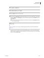
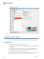
Figure 1.1 Biomek Main Editor
1. Step Palettes: Icons representing predefined steps for building methods are displayed in this area.
2. Method View: Place in this area the steps you want your method to complete.
3. Configuration View: The configuration for each step appears in this area. The view changes to
correspond to the step highlighted in the Method View.
4. Current Deck Display: This display changes dynamically to reflect the status of the deck upon
completion of the previous step.
Beginning a Method
To begin a method, you have the option of creating a new method or opening an existing method
you've completed, named, and saved. In this tutorial, you'll create a new method.
But before you create a new method, get into the habit of ensuring you are using the correct Project
File.
1-2
PN A99502AA
Getting Started
Beginning a Method
Introducing Project Files
While Project Files may be created, revised, deleted, imported, or exported, in this tutorial you will
use the Project File on your system that was created or imported when your instrument and Biomek
Software were installed.
Biomek Concept: Project File
A Project File stores information about liquid types, labware and tip types, well patterns, and
pipetting templates and techniques as revisions that are used by a method file to configure the
actions of the instrument. Project Files store a history of all changes, additions, and deletions of
items from the Project File. Methods are associated with projects and contain all of the items
required to perform the method.
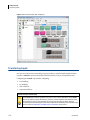
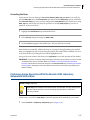
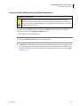
View Figure 1.2 to learn where Project File information is accessed or viewed from the main editor.
Figure 1.2 Project File
1. The actions and editors associated with Project Files are displayed in the drop-down
menu under Project on the toolbar.
2. Project File: The currently opened Project File is displayed here. The Project File
displayed here is the default for the Biomek 4000 instrument.
PN A99502AA
1-3
1
Getting Started
Beginning a Method
Adding Tools to Biomek Software
To make tools available for use in Biomek Software:
1
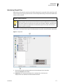
In Biomek Software, select Instrument > Hardware Setup. Biomek Hardware Setup appears.
2
In Biomek Hardware Setup, select
3
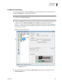
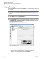
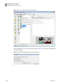
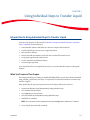
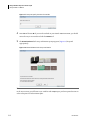
In New Devices, select the devices to add (Figure 1.3) to Biomek Software, and then select Install.
.
NOTE For this tutorial, you will need to add the P200L, MP200, and, if available, the Gripper.
Figure 1.3 New Devices
4
In Biomek Hardware Setup, select
to complete the process.
Creating a New Method
Biomek Concept: Method
A method is a series of steps that control the operation of the instrument. The step palettes in
the main editor present a group of icons representing the steps available for a method. To build
a method, you simply select the step icon you want, and move it into the method-building space
(Method View) in the main editor. Place and configure each step to perform the operations as
desired.
1-4
PN A99502AA
Getting Started
Beginning a Method
To create a new method:
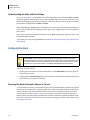
1
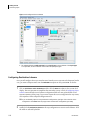
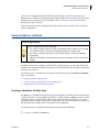
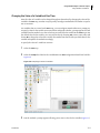
Select the New Method icon located on the toolbar (Figure 1.4).
This creates the beginning for your new method. It's a good idea to expand the Biomek editor to fill
the entire screen.
Figure 1.4 Main Editor When a New Method is Created
1. New Method
PN A99502AA
1-5
1
Getting Started
Setting Up the Deck
Understanding the Start and Finish Steps
As you can see (Figure 1.4), the Method View of the main editor now contains the Start and Finish
steps that appear automatically when you create a method. These two steps are always there and
indicate the beginning and end of your method. You'll insert all the rest of the steps you want the
instrument to complete between Start and Finish.
When the Start step is highlighted in the Method View, you are presented with the opportunity to
create some variables in the Configuration View. Ignore this configuration for our first chapter in
this tutorial.
If you want to know more in-depth information on the Start configuration right now, refer to the
Biomek 4000 Software Manual.
You'll learn more about using the Finish step in Determining the Estimated Time of Completion (ETC)
of the Method.
Setting Up the Deck
Biomek Concept: Deck Editor
The Deck Editor is used to define and change the deck configurations stored in the current
instrument file. A deck is a software visual representation of the deck and can be stored and used
for multiple methods; however, the software deck must always match the physical deck of the
instrument used in the method. Refer to the Biomek 4000 Software Manual for details.
Setting up the deck includes:
• Ensuring the current deck used in Biomek Software via the Deck Editor matches the physical
deck of the instrument.
• Configuring the Instrument Setup step to tell the software what labware and what deck position
each labware piece occupies on the deck.
Ensuring the Deck in Biomek Software is Correct
To avoid hardware crashes, it is important that the deck in Biomek Software matches the physical
deck of your instrument and is properly framed (refer to the Biomek 4000 Hardware Manual). If you
wish to run these tutorial methods on hardware rather than in simulation mode and your deck
varies from what is shown (Figure 1.5), you need to either create a deck both physically and in
Biomek Software to match the setup within this tutorial or modify the methods contained in this
manual to work with your hardware. For instructions on setting up your deck to match this tutorial,
see Creating a New Deck.
1-6
PN A99502AA
Getting Started
Setting Up the Deck
Figure 1.5 Current Deck for This Tutorial
1. Current Deck
Creating a New Deck
To create a deck to match the deck used in all tutorials in this manual:
1
From the Instrument menu, select Deck Editor. Deck Editor appears, showing the Default Deck
setup.
2
Select New Deck.
3
Enter a name for the new deck and select OK.
The Default Deck setup remains as a template, allowing you to make minor modifications if
needed. For this tutorial, you are going to create the deck from scratch.
4
PN A99502AA
Select Clear Deck to remove all positioners associated with the Default Deck.
1-7
1
Getting Started
Setting Up the Deck
5
From the ALPs Type List, select and drag one of the following into the upper left on-deck
position:
• ToolRack
OR
• ToolRackGripper, if your instrument is equipped with the optional Gripper tool
The tool rack appears on the deck as Rack1 when you finish placing the position.
6
Place a Biomek4000Position positioner directly to the right of Rack1 using the same method
described in the step above. Continue placing two more Biomek 4000 positions on the same
row, each to the right of the previous positioner. These positions appear as P1, P2, and P3.
7
Place two additional Biomek4000Position positioners on the deck, the first directly under
position P2, and the second directly under position P3. These positions appear as P4 and P5.
8
Place two ManualLatch positioners on the deck, placing the first one directly under Rack1, and
the second one under position P1. These positions appear as ML1 and ML2.
NOTE Manual Latch positioners enable the placement of tip boxes.
9
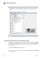
Your new deck should match Figure 1.6. Select Save to save your new deck and exit from the
Deck Editor.
Figure 1.6 Tutorial Deck Setup
1-8
PN A99502AA
Getting Started
Setting Up the Deck
Configuring the Instrument Setup Step
The next activity of this tutorial is to configure the Instrument Setup step for your liquid-transfer
procedure. You will place on the deck:
• P200L tool
• Tips
• Source reservoir
• Destination microplate
TIP If the Instrument Setup step, or any step, is inserted into the wrong location in the Method View, you can
drag and drop it to the proper location.
To insert the Instrument Setup step:
PN A99502AA
1
Choose (highlight) Start in the Method View.
2
Hover the cursor over the Instrument Setup icon in the step palette. As you hover, look at the
Method View and you'll see a black bar appear just below > Start. This black bar indicates the
insertion point where your next step will appear. In this case, it's where the Instrument Setup
step will be inserted.
3
Click the Instrument Setup icon to insert the step. The Instrument Setup configuration appears
(Figure 1.7).
1-9
1
Getting Started
Setting Up the Deck
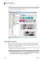
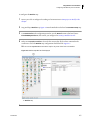
Figure 1.7 Instrument Setup Step Configuration
1. Deck Selection: Change the current deck setup by selecting another deck previously created using
the Deck Editor.
2. Labware Available: Represents the labware choices for your method. Move your selections onto the
Deck Layout display.
3. Move this scrollbar down to display all the labware choices.
4. Deck Layout: Represents the layout of your deck. Place your labware selections onto the desired deck
layout positions.
Using the Instrument Setup step you just inserted, you'll learn how to select and place:
• P200L tool at Rack1
• AP96_200μL tips onto ML1 deck position
NOTE Tip boxes must be placed on ManualLatch (MLx) or AutoLatch (ALx) positions.
• BCUpsideDownTipBoxLid reservoir onto P5 deck position
• BCFlat96 microplate onto P4 deck position
1-10
PN A99502AA
Getting Started
Setting Up the Deck
To select and place your tool and labware:
1
Verify that your deck matches the deck setup shown in Figure 1.7. If your current deck does not
match, select the appropriate deck from the Deck drop-down.
2
On the Deck Layout, double click the tool rack and drag a P200L tool into one of the slots. Click
OK and you will see that the tool rack graphic in the Instrument Setup step now lists a P200L tool
as occupying the space where it was dropped.
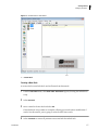
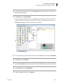
3
Click the AP96_200μL tips icon, and then click on the ML1 deck position. Notice that when you
hover the cursor over the tip box on the Deck Layout, an InfoTip (Figure 1.8) identifies the deck
position and labware. This technique applies to all the labware you place on the deck.
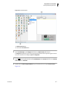
Figure 1.8 InfoTip
1. InfoTip: Identifies the deck position and labware type.
4
Using the above procedure, place a BCUpsideDownTipBoxLid reservoir onto the P5 deck
position.
5
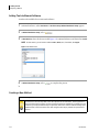
After you have positioned the reservoir on the deck, either double click it or right click and
select Properties. This opens Labware Properties (Figure 1.9). Each piece of labware added to the
Deck Layout is configured using Labware Properties. The information provided in Labware
Properties is used when a pipetting technique is selected or when tips are loaded and unloaded.
NOTE A technique instructs the Biomek instrument in performing pipetting operations, such as aspirate,
dispense, and mix.
PN A99502AA
1-11
1
Getting Started
Setting Up the Deck
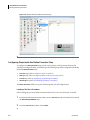
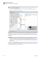
Figure 1.9 Labware Properties for Reservoir
6
In Labware Properties, you can give the reservoir a name. You'll name this one “Rsvr,” but in
general you can assign labware any name you want. Type Rsvr in the Name field. After
configuration is complete, the name will appear over the reservoir in the Current Deck display
(Figure 1.10).
TIP It is helpful to name your labware on the deck. You can assign a name that identifies the contents of
the labware, or a descriptive name that fits the work being done in your laboratory. This can reduce
confusion considerably.
7
Leave Bar Code blank for this tutorial, but it can be used to identify a specific plate in certain
methods.
8
In Labware contains an, select Known.
9
In the Volume field, type 100000. This means you know you have 100,000 microliters of liquid in
the source reservoir.
10 Choose Water from the Liquid Type drop-down menu, or type Water into this field.
11 Ignore the two options to Sense the liquid level. Since we have known volumes in the labware,
we won't use liquid level sensing in this chapter, but you'll use liquid level sensing in later
chapters.
12 Choose OK.
13 Place a BCFlat96 microplate onto the deck in position P4.
14 Double click on the P4 microplate, or right click and select Properties.
1-12
PN A99502AA
Getting Started
Setting Up the Deck
15 Type Dest in the Name field.
16 In Labware contains an, select Known.
17 In the Volume field, leave this value at 0.
18 Do not specify a Liquid Type for this destination plate since it is presently empty. The software
defaults to Water as the Liquid Type. To remove the default liquid type, delete Water from the
Liquid Type field.
NOTE All liquids specified in Biomek Software are tracked and will be listed in the Liquid Type drop-down
once a new type is added.
19 Choose OK.
That's it. Your deck is now set up for transferring liquid, and the main editor should look like
Figure 1.10.
TIP You can set the properties (name, volume, and liquid type) as you've just done in these steps, then drag
the labware back up, and drop it into the Labware Available display once you've selected the Custom
labware category. This labware will retain the properties you set and be available to use in other methods
when you access Instrument Setup.
PN A99502AA
1-13
1
Getting Started
Transferring Liquid
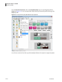
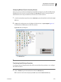
Figure 1.10 Instrument Setup Step Completed
Transferring Liquid
Now you are ready to insert and configure your procedure to transfer liquid. Biomek Software
provides a Transfer step on the Basic Step Palette that makes it easy to accomplish this task.
Configuring the Transfer step includes configuring:
• Tool handling
• Tip handling
• Source labware
• Destination labware
Biomek Concept: Transfer Step
The Transfer step transfers liquid from one source to one or more destinations. The Transfer
step will by default complete the following: load tool, load tips, aspirate liquid, dispense liquid,
and unload tips. This concept eliminates the need to insert five separate steps, although
occasionally a method may require these steps be performed individually. These individual steps
will be covered in CHAPTER 2, Using More Steps in a Method, of this tutorial.
1-14
PN A99502AA
Getting Started
Transferring Liquid
Configuring Tip Handling
To set up a liquid transfer, insert the Transfer step into the Method View in the main editor, and
configure Tip Handling by completing the following:
1
Highlight the Instrument Setup step.
2
Choose the Transfer icon from the step palette, and insert it into the method by dragging and
dropping it after the Instrument Setup step. The Transfer step configuration appears
(Figure 1.11). Notice the Current Deck Display at the bottom of the editor is now populated to
illustrate your deck setup since it changes dynamically to match the state of the deck at the
start of the current step.
Figure 1.11 Transfer Step Inserted
1. Transfer step icon
3
PN A99502AA
Make sure the type of tips displayed is AP96_200μL, the type of tips you configured in the
Instrument Setup step.
1-15
1
Getting Started
Transferring Liquid
4
Make sure unload them is selected in the next field.
5
Allow the default Change tips between destinations to be checked.
6
Your tips are configured for your liquid transfer, so click the up arrow next to Tip Handling
(Figure 1.11). This collapses the Tip Handling configuration to allow more room for labware
configuration. A simple text description of the way tips will be handled is displayed in place of
the expanded Tip Handling configuration. The editor now looks like (Figure 1.12).
Figure 1.12 Tip Handling Configured and Collapsed
1. Tip Handling collapsed
1-16
PN A99502AA
Getting Started
Transferring Liquid
Configuring Source Labware
Now you will configure the source labware. Here you will specify from which labware liquid will be
aspirated and the height to which the tip descends into the labware before aspirating.
To configure the reservoir named Rsvr as the source labware:
1
Click on Click here to add a source.
2
Click on Rsvr labware on the P5 position in the Current Deck display. As you can see, the
information you supplied in the Instrument Setup step is displayed in the source labware
configuration.
3
Right click on the large tip illustration next to the reservoir graphic in the configuration and
choose Measure from Bottom.
TIP After you click on the tip, you can adjust the height more precisely by using the up or down arrow
keys on your keyboard to change the height by 0.10 mm, or you can use the Page Up and Page Down
keys to change the height by 1.0 mm with each press of the key. You can also right click on the
graphic, then select Custom Height from the menu that appears.
4
To adjust and set the aspirate height to which the tip descends into the reservoir, place the
mouse cursor over the tip illustration. When the cursor turns into a hand, hold the left mouse
button down to move the hand up and down until the depth is as close to 5.00 mm from bottom
as you can get. Then, adjust the height precisely to 5.00 mm using the Tip described above.
There is a slight break in the bottom of the source reservoir graphic with the large tip that
indicates that the reservoir is wider than the graphic can display.
OR
To select a custom height, right click on the illustration and select Custom Height, and then
select Bottom from the drop-down menu. Type 5.00 in the text box, and then click OK.
The source labware is complete, and the editor now looks like Figure 1.13.
PN A99502AA
1-17
1
Getting Started
Transferring Liquid
Figure 1.13 Configured Source Labware
1. The software defaults to Well Contents for the Liquid Type for Source labware. The Liquid Type
is not specified, as Source labware could contain multiple liquid types.
Configuring Destination Labware
Here you will configure where you want the water from the source reservoir to be dispensed. In this
case, you want to dispense water into the BCFlat96 microplate on deck position P4. To do this:
1
Click on Click here to add a destination and the click the Dest microplate in the current deck
display. This one operation accomplishes the same tasks as steps 1 and 2 of Configuring Source
Labware. Notice that the source labware configuration fields are now replaced with a brief
sentence summary of the setup. If you want to reopen this source configuration for any reason,
click anywhere in the collapsed configuration area.
TIP If you accidentally open too many destination configurations, just right click on the title in the
configuration. Click Delete from the popup menu and the entire configuration goes away.
2
1-18
Double click the Destination Labware in the step configuration to zoom in on the labware. All of
the wells are selected by default.
PN A99502AA
Getting Started
Transferring Liquid
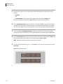
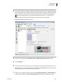
3
Since all of the wells are selected by default, select the first well of the first column by clicking
on the well. Now the only well that is selected is that first well that you just clicked; all the other
wells are deselected. Then, select every other well of the first six columns by holding down
(Ctrl) key and clicking the wells. Your pattern should look like Figure 1.14. You have just
configured which wells will be filled with water from the source reservoir Rsvr.
Figure 1.14 Destination Labware Zoomed In
PN A99502AA
4
Allow the default selections in Direction, Start, and Mark last well that is used to remain.
5
Choose Zoom Out.
6
Select the volume field, which allows you to designate the amount of liquid to be dispensed. For
this tutorial, you're transferring 100 μL; so type 100 into the Volume field. This means you will
be dispensing 100 μL into each of the wells you selected.
7
Right click on the large tip illustration and choose Measure from Bottom or Custom Height and
set the dispense height to 1.00 mm from the bottom using whichever technique you prefer.
1-19
1
Getting Started
Transferring Liquid
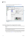
The destination labware is now configured and the editor looks like Figure 1.15.
Figure 1.15 Configured Destination Labware
1. Volume field
Determining the Estimated Time of Completion (ETC) of the Method
Your liquid transfer is set up, so let's see how long it will take to run the entire method by using the
Finish step.
To do this:
1-20
1
Click on the Finish step in the Method View.
2
Check the status bar at the bottom of the editor for a display of the ETC. For this method, the
ETC is approximately 8:15 (Figure 1.16). It's all right if your ETC varies slightly.
PN A99502AA
Getting Started
Transferring Liquid
Figure 1.16 Finish Step Displaying the ETC
1. ETC: The Estimated Time of Completion for the method in the Method View.
Congratulations! You've just built a liquid transfer method using Biomek Software that:
• Prepared the main editor for a new method.
• Set up the deck and configured the labware you wanted to use using an Instrument Setup step.
• Added and configured a liquid transfer using a Transfer step.
PN A99502AA
1-21
1
Getting Started
Running the Method
Running the Method
Now that you've built a method, let's run it.
IMPORTANT If you have not already configured the physical deck and you are planning to run the method
on hardware rather than in Simulation Mode (see Viewing the Method in the Biomek Simulator), add the
labware and tools as specified in the Instrument Setup step (see Configuring the Instrument Setup Step).
Verifying that the correct labware and tools are used ensures proper pipetting and labware handling.
Validating the Method and Confirming the Deck Setup
When you select Run, the method will be validated internally to check for errors. After this
validation is complete, a deck confirmation prompt will appear over the main editor (Figure 1.17).
This prompt displays the deck setup as interpreted by the software.
If you wish, you can also view the method in the Biomek Simulator. Refer to Viewing the Method in
the Biomek Simulator.
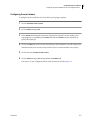
To confirm the deck setup:
1
Click on the green arrow button on the toolbar, or from the Execution menu, choose Run. A deck
confirmation appears (Figure 1.17).
Figure 1.17 Deck Confirmation Prompt
2
1-22
Visually confirm the physical deck setup matches the deck confirmation.
PN A99502AA
Getting Started
Running the Method
3
Choose OK if the deck confirmation matches the physical deck setup or choose Abort and then
change the Instrument Setup step to match the physical deck setup. The method runs as soon
as you choose OK. You can visually follow the run in the Method View; steps are highlighted as
the step is executed.
Viewing the Method in the Biomek Simulator
CAUTION
Make sure the proper port is selected in the "Hardware Setup" window within
Biomek Software. "Simulate" is used only when running methods on the Biomek
Simulator, and will not initiate the physical instrument to run. To run methods on
the instrument, choose the COM port to which the instrument is connected.
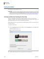
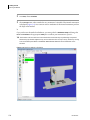
When a method is run in simulation, the Biomek Simulator appears, showing an animated 3-D
model of the instrument performing the method. Setting the simulation mode is configured in
Hardware Setup (Figure 1.18).
Biomek Concept: Hardware Setup
Hardware Setup is used to configure Biomek Software with the appropriate Biomek instrument
information, including the Biomek Simulator. While the Beckman Coulter Representative normally
installs and configures new devices, it may be necessary to install, configure, and remove other
devices using Hardware Setup. Refer to the Biomek 4000 Software Manual.
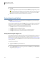
If you wish to view the method in simulation:
1
From the toolbar, choose Instrument > Hardware Setup. Hardware Setup appears (Figure 1.18).
Figure 1.18 Hardware Setup
1. Choose Simulate here to allow methods to be run in the Biomek Simulator.
PN A99502AA
1-23
1
Getting Started
Running the Method
2
From Port, choose Simulate.
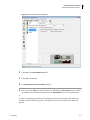
3
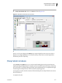
Choose Accept. Now, when a method is run, an animated 3-D model of the Biomek instrument
is displayed (Figure 1.19). You can now watch a simulation of the Biomek instrument perform
the steps in the method.
If you wish to run the method on hardware, you must go back to Hardware Setup and change the
Port from Simulate to the appropriate COM port to connect your instrument to your PC.
TIP The simulator can be a useful tool to test methods to ensure that they are performing as expected
without using up valuable reagents or tips, and can also save time not only in set up, but also by running
at an accelerated speed. Refer to the Biomek 4000 Software Manual for more information on the
simulator.
Figure 1.19 Running a Method in Simulation
1-24
PN A99502AA
Getting Started
Saving a Method
Saving a Method
You will save the method you've just created.
Biomek Concept: Saving Methods
Methods can be saved at any time during their development. Saving a method automatically
creates a record of the revision that preserves the method configuration at the time it was saved.
Revisions may be accessed from the revision history at a later time. If any project items, such as
labware definitions or techniques, change after the method is saved, when the method is opened
next, the latest definitions are used. Refer to the Biomek 4000 Software Manual for additional
details.
To save your method:
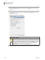
1
Choose
2
In Method Name, type the file name under which your method will be saved. For this chapter,
type Getting Started Tutorial (Figure 1.20).
(Save Method) on the toolbar.
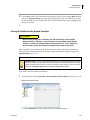
Figure 1.20 Save Method
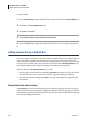
3
PN A99502AA
Choose OK. Now notice how the method name in the Biomek main editor has changed to Getting
Started Tutorial [Revision 1] (Figure 1.21).
1-25
1
Getting Started
Saving a Method
Figure 1.21 Method Name Has Changed
Now go to the next chapter to learn how to use more steps in a method.
1-26
PN A99502AA
CHAPTER 2
Using More Steps in a Method
Introduction to Using More Steps in a Method
In the previous chapter of this tutorial (refer to CHAPTER 1, Getting Started), you learned how to:
• Launch Biomek Software.
• Set up the deck for a liquid transfer.
• Build a liquid-transfer method.
• Save and run a method.
If you already know how to complete these tasks, you can start with this chapter or subsequent
chapters.
What You'll Learn in This Chapter
This chapter will help you develop the skills to create methods for tasks such as transferring liquid
from tubes to plates, liquid level sensing, and serial dilution. You will also learn how to pause the
system to add more labware to the deck and handle errors. Using Single Step to perform single
operations to improve method development will also be described.
In this chapter, you will learn how to:
• Transfer liquid from two sources to a single destination.
• Mix contents in labware.
• Move labware on the deck using the optional Gripper tool.
NOTE Your Biomek 4000 instrument must be equipped with the optional Gripper tool to move labware.
• Remove and add labware to the deck once a method has started to run.
• Group steps logically in the Method View.
• Use the automatic serial dilution feature.
• Respond to errors.
• Perform single operations.
PN A99502AA
2-1
Using More Steps in a Method
Introduction to Using More Steps in a Method
Setting Up Your Deck for This Chapter
Using what you learned in CHAPTER 1, Getting Started, launch Biomek Software and configure an
Instrument Setup step with the following:
1
Place a P200L tool in the tool rack by double clicking the tool rack displayed in the
Configuration View and selecting the P200L icon and dragging into one of the slot positions.
Repeat this procedure for the MP200 tool, using one of the other open slots, and the Gripper, if
your instrument is equipped with an optional Gripper tool.
NOTE To place the optional Gripper on your tool rack, you must have a ToolRackGripper on your deck,
rather the 5-slot ToolRack. For the purposes of this tutorial, the ToolRackGripper is installed on the
deck. The Gripper can only be placed in the Gripper slot, which is custom-sized to fit the Gripper tool.
2
Place an AP96_200μL tip box on ML1.
3
Place SmallTuberack_Microfuge tube racks on P4 and P5 and name them Tubes1 and Tubes2.
Give these a Nominal volume of 1000 μL of Water and choose Sense the liquid every time a well
is accessed "from the Liquid." Sensing the liquid level from the Liquid helps pipetting
performance since air will not be likely to be aspirated along with the liquid. Refer to the
Biomek Concept below.
Biomek Concept: Liquid Level Sensing
Liquid level sensing is used to determine the liquid level within a piece of labware using
specially-designed LLS tools. Refer to the Biomek 4000 Hardware Manual for details.
4
Place a BCFlat96 on P2 and name it Dest. Give this microplate a Known volume of 0 μL.
5
If your instrument is equipped with the Gripper tool, place a TiterPlateLid onto the deck at P3.
Your deck should look like Figure 2.1. Now go to the next activity to learn how to use other steps in
your methods.
2-2
PN A99502AA
Using More Steps in a Method
Transferring Liquid from Multiple Sources to a Single Destination
Figure 2.1 Completed Instrument Setup Step
Transferring Liquid from Multiple Sources to a Single Destination
To transfer liquid from one or more sources to a single destination, a Combine step is used. It is
similar to a Transfer step which uses a single source and one or more destinations.
Like the Transfer step, the Combine step will by default complete the following:
• Load tool
• Load tips
• Aspirate liquid
• Dispense liquid
• Unload tips
For this activity, you will use the default tip handling, configure the two sources, configure the
destination, and configure transfer details to perform a tube-to-plate transfer and pool samples
into the first column of 96-well plate.
PN A99502AA
2-3
2
Using More Steps in a Method
Transferring Liquid from Multiple Sources to a Single Destination
Configuring Tip Handling
To set up the Combine step, you will insert the Combine step in the Method View and configure the
step. To do this:
1
Ensure your deck is configured according to the instructions in Setting Up Your Deck for This
Chapter.
2
Add a Combine step after the Instrument Setup step.
3
Collapse Tip Handling since you will use the default settings for your liquid transfer. Make sure
Load AP96_200μL tips, change between sources, and unload them when finished is displayed.
Your main editor should look like Figure 2.2.
Figure 2.2 Combine Step Inserted and Tip Handling Collapsed
1. Load Tool field: This field is available for Transfer or Combine steps. You can either
specify a tool using the drop-down, or you can leave the default as <AutoSelect>,
where the software selects the appropriate tool based upon the tips you have selected
for the step. Each tip type has a set of compatible tools, and these tools are prioritized
based on the degree of compatibility with that tip. Compatible tools associated with
each tip type can be viewed and changed using the Tip Type Editor.
2-4
PN A99502AA
Using More Steps in a Method
Transferring Liquid from Multiple Sources to a Single Destination
Configuring Source Labware
To configure the two small tube racks from which you're going to aspirate:
1
Click on Click here to add a source.
2
Click on Tubes1 sitting on P4.
3
In the Volume field, designate the amount of liquid to be aspirated. For this method, you're
aspirating 25 μL, so type 25 into the Volume field and select Water from the drop-down to
specify the liquid type.
4
Click on the Dest plate in the Current Deck Display to add a destination. You will configure the
destination in the next section, but must choose it here to activate another source option.
5
Click on the next Click here to add a source.
6
Click on Tubes2 sitting on P5 and type 25 into the Volume field.
The sources are now configured, and the editor should now look like Figure 2.3.
PN A99502AA
2-5
2
Using More Steps in a Method
Transferring Liquid from Multiple Sources to a Single Destination
Figure 2.3 Source Labware for Combine Step Configured
1. Well Volume Display
TIP The well volume display shows how much liquid is in the well. If the liquid is not visible in the display,
you may be accidentally trying to aspirate from an empty destination rather than a source.
Configuring Destination Labware
The next task is to designate where you want to dispense the aspirated liquid. For this method, you
want to dispense into the first column of the 96-well plate on deck position P2. To accomplish this:
2-6
1
If necessary, scroll down until you see Destination: Dest. Click anywhere in the Destination: Dest
configuration.
2
Double click the Destination labware graphic in the Step Configuration.
3
Select only the wells in the first column.
4
Choose Zoom Out.
PN A99502AA
Using More Steps in a Method
Mixing Contents in Labware
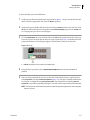
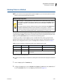
5
In Stop when finished with, make sure Sources is chosen (Figure 2.4).
Figure 2.4 Stop When Finished with Sources Chosen
That's it. You've just configured a Combine step to aspirate liquid from two sources in order to
dispense it to a single destination. Go to the next activity to learn how to mix the liquid in the
destination plate after dispensing.
Mixing Contents in Labware
In the Transfer and Combine steps, you can alter liquid-handling functions that extend beyond
simple aspirating and dispensing. For example, you can turn off the tip touch feature, activate the
pre-wet function, or configure mixing operations. These modifications are accomplished through
customizing the technique and are used to control the pipetting process.
Let's suppose you wish to mix the contents of the destination plate once liquid from the two sources
has been dispensed.
To complete this task:
PN A99502AA
2-7
2
Using More Steps in a Method
Mixing Contents in Labware
1
Select the Destination: Dest labware configuration in the Combine step, if it is not already
selected.
2
In the Destination configuration fields, select Customize. The Technique Editor opens to the
Dispense tab (Figure 2.5).
Figure 2.5 Dispense Tab of the Technique Editor
Biomek Concept: Techniques
Techniques are sets of predefined and stored values, including aspirate and dispense height,
tip touch and other properties that affect pipetting. Based upon these stored sets of values
and properties, the appropriate pipetting technique is selected automatically. If you want
control over this otherwise automatic function, you can choose Customize for each source
and destination in a liquid transfer. This customizing option is also available via the
Technique Editor. Refer to the Biomek 4000 Software Manual.
2-8
PN A99502AA
Using More Steps in a Method
Mixing Contents in Labware
Configuring “Mix after dispensing liquid”
Now, you will configure the options to mix the contents in the destination after dispensing.
To mix after dispensing:
1
From the Dispense tab (Figure 2.5), check Mix after dispensing liquid. The fields for this option
are enabled. We'll allow some of the defaults to remain except for the amount and number of
times to mix.
2
In Mix, enter 25. This specifies the volume in microliters (μL) that will be aspirated and
dispensed during mixing.
3
In time, enter 2. This specifies the number of times you want to mix the liquid after dispensing.
You're finished configuring the mix after dispensing process. The Technique Editor should now
look like Figure 2.6.
TIP Pipetting from the Bottom can sometimes cause wells to overflow, or it can contaminate the tips.
Aspirating and dispensing from the liquid would be a good choice in these cases. This is not a concern
for this tutorial, so you are leaving the default.
Figure 2.6 Configured Mix in a Custom Technique
PN A99502AA
2-9
2
Using More Steps in a Method
Moving Labware Around the Deck
4
Choose OK.
After you configure the mix operation and return to the Combine step configuration, you see a
icon, indicating that the technique now includes mixing. This is one of several icons that
indicate different procedures in the pipetting technique. You will also notice that the AutoSelect option is turned off when the technique has been customized.
Moving Labware Around the Deck
IMPORTANT If your instrument is not equipped with the optional Gripper tool, skip this section and go to
Adding Labware During a Method Run.
If the instrument is equipped with an optional Gripper tool, you can move labware around the deck
during a method. On the step palette, you can see the Move Labware icon. When you insert and
configure this step in your method, the instrument behaves as follows:
• The Gripper tool moves over the selected labware and moves down.
• The Gripper tool squeezes and grips the labware.
• The Gripper tool moves up and carries the labware to the designated position.
• The Gripper tool moves down, and releases the labware at the new position.
Moving Labware Using the Gripper Tool
For this part of the tutorial, let's suppose that the contents of the destination plate are sensitive to
light and need a lid to keep them from decomposing. Let's suppose further that you have a titer
plate lid on the deck. Using a similar deck setup to the one that you created in Setting Up Your Deck
for This Chapter, you will use the Gripper tool to move the titer plate lid to the position with the light
sensitive compound.
To move labware on the deck:
2-10
1
Highlight the Combine step in the Method View.
2
Insert the Move Labware step from the step palette after the Combine step. The Move Labware
configuration appears (Figure 2.7).
PN A99502AA
Using More Steps in a Method
Moving Labware Around the Deck
Figure 2.7 Move Labware Step Configuration
3
Choose P3 in the Move labware from field.
4
Choose P2 in the to field.
5
Keep Move the entire stack of labware selected.
6
Now, click on the Finish step in the Method View following the Move Labware step to validate
the method. The Current Deck Display shows the TiterPlateLid now at its new position, P2.
In order to complete the procedures in the following sections, the well plate on P2 needs to be
available for a serial dilution procedure, and therefore, the lid must be removed to make that
possible.
PN A99502AA
2-11
2
Using More Steps in a Method
Adding Labware During a Method Run
To remove the lid:
1
Insert a Move Labware step into the Method View directly under the current Move Labware step.
2
Choose P2 in the Move labware from field.
3
Choose P3 in the to field.
4
Select Move the topmost 1 piece of labware from the stack.
5
Select the Finish step to validate the method. The lid is now back on its original position, P3.
Adding Labware During a Method Run
Now you are ready to add labware to the deck for another liquid transfer process. Suppose that you
want to add another reagent to the destination plate, but you don't want to place the second
reagent on the deck until after the first Transfer is complete (perhaps it can only be exposed to light
or open air for a very short time). This means that you will add a second Instrument Setup step to
your method to indicate to the software that there is more labware now on the deck.
Before you add a second Instrument Setup step, you will:
• Move the pod to a new location by configuring a Move Pod step to make sure the pod is moved
to a part of the deck where it won't prevent you from physically adding more labware.
• Pause the instrument by configuring a Pause step to give you enough time to physically add
more labware.
Moving the Pod to a New Location
The Move Pod step is used to reposition the pod away from the positions on the deck you want to
reach manually. Since you are going to be adding more labware to the deck to prepare for another
liquid transfer, you will need to move the pod away from the deck locations affected before pausing
the system and adding more labware.
2-12
PN A99502AA
Using More Steps in a Method
Adding Labware During a Method Run
Displaying the Intermediate Step Palette
Biomek Concept: Step Palettes
Steps are grouped on step palettes based upon the complexity of the operations they control and
the depth of knowledge required to configure them, although some steps are grouped on step
palettes according to the specific pod or instrument they control.
The Move Pod step is located on the Intermediate Step Palette. You will need to add the
Intermediate Step Palette to the main editor:
1
Right click anywhere in the space below the Basic Step Palette.
2
Choose Intermediate. The Intermediate Step Palette appears on the main editor (Figure 2.8).
Figure 2.8 Intermediate Step Palette Displayed
1. Move Pod Step
2. Intermediate Step Palette
PN A99502AA
2-13
2
Using More Steps in a Method
Adding Labware During a Method Run
Configuring the Move Pod Step
To configure the Move Pod step:
1
Insert the Move Pod step in the Method View in one of the following locations:
• If your instrument is equipped with a Gripper, and you completed the instructions in
Moving Labware Around the Deck, insert the Move Pod step after the second Move Labware
step.
• If your instrument is not equipped with a Gripper, insert it after the Combine step.
2
From the Location drop-down menu, choose P1. This instructs the pod to move and stop over
the P1 position (Figure 2.9).
Figure 2.9 Configured Move Pod Step
3
2-14
Click Finish to validate the method.
PN A99502AA
Using More Steps in a Method
Adding Labware During a Method Run
Pausing the Instrument
The instrument may be paused during a method run for either a specified amount of time or for an
indefinite period of time by adding and configuring a Pause step. Depending on the purpose of the
pause, you configure the step in one of the following ways:
• If you want to incubate a piece of labware in a specific position for a specific amount of time,
you configure the desired time in seconds that you want that position to be idle and unavailable
for interaction with the instrument.
• If you want to move labware manually during a method (either move it around on the deck, or
remove it from the deck to take it to a device, such as a reader), you configure the step to pause
the instrument for an indefinite period of time.
When the Pause step occurs during a run, the pod remains in the position of the last operation.
Configuring the Pause Step
You will configure the Pause step for indefinite amount of time to add more labware to the deck
manually. The software will display a message on top of the main editor until you complete your
manual operations, at which time it will resume the method run.
To configure the Pause step for an indefinite amount of time:
1
Insert a Pause step into the Method View below the Move Pod step.
2
Choose Pause the whole system and display this message:
3
Replace Paused in the message box by typing in the message:
Remove and store the tube racks located at P4 and P5.
Remove the tip box at ML1.
Place a diluent reservoir at P4.
Place new tip boxes at ML1 and ML2.
The main editor should now look like Figure 2.10.
PN A99502AA
2-15
2
Using More Steps in a Method
Adding Labware During a Method Run
Figure 2.10 Pause Configuration With Message Inserted
When the method is run, you will see a prompt similar to Figure 2.11 that will remain displayed
until you choose OK.
Figure 2.11 Pause Prompt Displaying the Configured Message
2-16
PN A99502AA
Using More Steps in a Method
Adding a Second Instrument Setup Step
Adding a Second Instrument Setup Step
Now that you have prepared to add more labware to the deck during a method, you are ready to
configure a second Instrument Setup step. You will insert a second Instrument Setup step after the
Pause step. The second Instrument Setup step not only indicates the current state of the deck, but
it also allows you to add more labware. But before you will add more labware to the deck, you will
remove some labware.
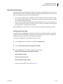
To configure the second Instrument Setup step:
1
Insert an Instrument Setup step into the Method View below the User Pause step. This opens a
second Instrument Setup step configuration.
2
Choose Toggle under the As Is square. This lets the software know that all deck positions are to
remain as they are. The main editor should now look like Figure 2.12.
Figure 2.12 Adding an Instrument Setup Step and Toggling All Deck Positions As Is
PN A99502AA
2-17
2
Using More Steps in a Method
Adding a Second Instrument Setup Step
3
Select Clear and then click on ML1, P4, and P5. This removes the tube racks and used tip box.
Now the main editor should look like Figure 2.13.
Figure 2.13 Using Clear to Remove Labware
Adding Labware to the Deck
Now you will add the labware to prepare for the next liquid-handing process, which is a Serial
Dilution. For this next liquid-handling process, you will need to add two more tip boxes and an
additional source reservoir. This new labware was what you configured to display when the
instrument paused for manual placement.
TIP Even though the software finds tips automatically, you have to ensure there are enough tips on deck to
do the job. If you don't, you will get an error message.
1
2-18
Place a BCUpsideDownTipBoxLid reservoir on P1 and name it Diluent. Configure the reservoir to
have an Unknown volume of Water. Make sure Sense the liquid level the first time a well with
Unknown or Nominal volume is accessed "from the Liquid" is selected.
PN A99502AA
Using More Steps in a Method
Adding a Second Instrument Setup Step
2
Place AP96_200uL tip boxes on positions ML1 and ML2.
3
Select
Figure 2.14).
to inform the software that a tool is currently loaded on the pod (see
Figure 2.14 Configure Pod Setup
1. Configure: Select to configure the current pod setup.
PN A99502AA
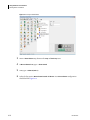
4
In Pod Setup, select the Tool Loaded check box.
5
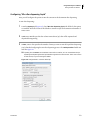
In the Tool Loaded drop-down (Figure 2.15), select the tool currently loaded on the pod.
2-19
2
Using More Steps in a Method
Using a Group Step
Figure 2.15 Pod Setup Configuration
6
In the Tool Rack drop-down, select the rack where the loaded tool is stored when not in use.
7
In the Rack Slot drop-down, select the rack slot where the tool is stored, and then select OK.
You may think that all the steps in the Method View make your method look complex. Go to the
next section to learn what you can do about that.
Using a Group Step
To prevent your method from appearing too complex, you can group steps together logically under
one unique heading by inserting the Group step into the Method View. This group of steps is hidden
in the Method View under the name that you've given it during configuration of the Group step.
Biomek Concept: Group Step
The Group step allows you to "nest" a series of connected steps together, and gives the group
a logical name that appears in your Method View. When you open your method, the Group step
appears collapsed with the connected steps hidden. This makes the method appear shorter, and
it allows you to see more of the method without scrolling the Method View up or down. You
simply double click on the Group step in the Method View to expand it and expose the nested
steps.
Configuring the Group Step
For this activity, you will group under one heading the Move Pod, Pause, and Instrument Setup steps
you already have in your method. These steps are all associated with the preparation for the serial
dilution.
2-20
PN A99502AA
Using More Steps in a Method
Using a Group Step
To group these steps:
1
Insert the Group step from the Intermediate Step Palette in the Method View before the Move
Pod step.
2
Double click on the Group step to reveal the End Group step. Scroll the Method View to the left
if necessary (Figure 2.16).
Figure 2.16 Expanded Group Step
1. Group step
PN A99502AA
3
In Group Label of the step configuration, enter Pause to remove and add labware.
4
Highlight the Move Pod step, then drag and drop it into the Group step above End Group.
5
Repeat step 4 above for the User Pause and the second Instrument Setup step.
2-21
2
Using More Steps in a Method
Using a Group Step
Now the Move Pod, User Pause, and second Instrument Setup steps are nested logically within a
Group step (Figure 2.17). You can expand and collapse this step as desired by double clicking on the
Group step title.
Figure 2.17 Configured Group Step With Nested Steps Expanded
Go to the next section to learn how to perform multiple dilutions of a sample on a single microplate.
2-22
PN A99502AA
Using More Steps in a Method
Performing Multiple Dilutions of a Sample
Performing Multiple Dilutions of a Sample
The Serial Dilution step is used to perform multiple dilutions of a sample on a single microplate. This
step transfers liquid from wells on a microplate to other wells on the same microplate and may also
add diluent to those wells.
Biomek Concept: Serial Dilution Step
The Serial Dilution step completes multiple dilutions by performing the following actions in
sequence:
•
•
•
•
•
•
•
Transfer a volume of diluent to all selected wells (optional).
Transfer a volume of sample from the first selected well to the next selected well.
Mix the solution via the Technique Editor.
Transfer a volume of solution to the next selected well.
Mix the solution via the Technique Editor.
Repeat transfer and mix operations until all selected wells are used.
Discard extra volume from last column or last wells.
For this next activity, we will use the sample in the first column in the microplate on P2.
PN A99502AA
1
Right click anywhere in the space below the Basic Step Palette.
2
Choose Span-8. The Span-8 Step Palette appears on the main editor.
3
Insert a Serial Dilution step after the collapsed Group step (Figure 2.18).
2-23
2
Using More Steps in a Method
Performing Multiple Dilutions of a Sample
Figure 2.18 Serial Dilution Step Inserted
4
In Use Tips, choose AP96_20uL.
5
Click on the Dest plate on P2.
6
In Liquid Type, choose Water.
7
In Volume, enter 50. This is how much liquid is transferred from one well to the next.
8
In Direction, make sure Left to Right is selected since you will be diluting across the rows of the
plate.
TIP With the Serial Dilution step, contiguous wells must be used. In Direction, Left to Right is faster.
NOTE Top to Bottom dilutions were not possible using Biomek 3000 instruments, as serial dilutions could
only be completed using multi-tip pipetting tools. Biomek 4000 serial dilutions allow use of multi-tip
or single-tip pipetting tools, thus allowing for dilutions to be performed one well at a time, in a
Top to Bottom or Left to Right direction.
2-24
PN A99502AA
Using More Steps in a Method
Performing Multiple Dilutions of a Sample
9
Check Discard extra volume from last wells and Change tips After Every Sample.
10 Select Diluent Properties to expand.
11 Check Add diluent before transfer.
12 Select the Diluent reservoir at P1. This means the diluent is added to all wells before the sample
transfers.
13 Configure the Dilution Ratio to 1:2 by entering 2 in the field. The dilution ratio is a ratio of
volume of sample to total solution, so a dilution ration of 1:2 means that for every μL of sample
there is 1 μL of diluent added, or a 50% dilution.
14 Make sure Change tips between diluent transfers is not checked.
15 Highlight the Finish step to validate the method. OOPS! The red indicates an error (Figure 2.19).
Go to the next section to learn how to correct this error.
PN A99502AA
2-25
2
Using More Steps in a Method
Responding to an Error Message
Figure 2.19 Error Displayed
Responding to an Error Message
For this activity, you'll learn how to locate and respond to the error message you just received.
Locating the Error
Biomek Software alerts you to errors in several ways, including:
• The step with the error appears in red in the Method View when any step following the error
is highlighted.
• A tool tip describes the error when you hover the cursor over the step causing the error.
• An associated red error message is displayed in the status bar at the bottom of the editor.
• The error is displayed in an error bar just above the status bar.
There are other errors that are displayed in error message boxes. These errors state the problem
and display appropriate recovery options. Refer to the Biomek 4000 Software Manual.
2-26
PN A99502AA
Using More Steps in a Method
Performing Single Operations With the Biomek 4000 Laboratory Automation Workstation
Correcting the Error
In this tutorial, the error message is Can not find labware {AP96_20μL} on deck. If you recall, you
selected AP96_20μL tips in the Serial Dilution step rather than the AP96_200μL tips you used in the
last Instrument Setup step. Since you have configured the Serial Dilution step to transfer 50 μL using
AP96_20μL tips, but the tips you placed on your deck are actually AP96_200μL tips, an error is
produced. To correct the error:
1
Highlight the Serial Dilution step in the Method View.
2
In the Use Tips, change the tip type to AP96_200μL.
3
Click the Finish step again in the Method View. The error has been corrected.
Biomek Software continually validates the steps as you progress through building your methods.
When you highlight any step, the steps above that point in the method will be validated. If an error
is encountered, the step causing the error will be highlighted in red.
Now go to the next section to learn how to use Single Step to view each operation of this method.
IMPORTANT If you have not already configured the physical deck and you are planning to run the method
on hardware rather than in Simulation Mode (see CHAPTER 1, Viewing the Method in the Biomek
Simulator), add the labware and tools as specified in the Instrument Setup step (see Setting Up Your Deck
for This Chapter). Verifying that the correct labware and tools are used ensures proper pipetting and
labware handling.
Performing Single Operations With the Biomek 4000 Laboratory
Automation Workstation
Biomek Concept: Single Step
Single Step pauses the Biomek instrument between each operation in a step, allowing visual
verification that the operation is correct. Performing single operations can help when
fine-tuning a method.
In this activity, you will use Single Step to view each operation of the method you just created:
1
PN A99502AA
Choose Execution > Single Step. Single Step appears (Figure 2.20).
2-27
2
Using More Steps in a Method
Performing Single Operations With the Biomek 4000 Laboratory Automation Workstation
Figure 2.20 Single Step
2
While Single Step is still open, choose Execution > Run from the grayed-out toolbar. Single Step
with specific operations displayed appears (Figure 2.21). If you have other ALPs configured on
your deck, the initialization process for them appears in Single Step.
TIP Go slowly when using Single Step. It is possible to move too quickly through the method and bypass
the steps that need verification.
Figure 2.21 Single Step With Specific Operations Displayed
2-28
3
Under Home the Z axis on Pod1, choose Launch. The next operation is launched.
4
Keep choosing Launch until the Biomek Software prompt appears (Figure 2.22). If the physical
deck matches the software prompt, choose OK. Single Step continues displaying each
operation, along with the option to Launch and execute that operation.
PN A99502AA
Using More Steps in a Method
Performing Single Operations With the Biomek 4000 Laboratory Automation Workstation
Figure 2.22 Biomek Software Prompt
5
Continue to view each operation by choosing Launch or to stop Single Step, choose Exit to allow
the method to run without the option to view each operation.
6
Clicking the Launch All button launches all of the steps currently displayed inside the Single
Step window.
Go to the next chapter to learn how to use individual steps to more precisely control a liquid
transfer.
PN A99502AA
2-29
2
Using More Steps in a Method
Performing Single Operations With the Biomek 4000 Laboratory Automation Workstation
2-30
PN A99502AA
CHAPTER 3
Using Individual Steps to Transfer Liquid
Introduction to Using Individual Steps to Transfer Liquid
In the previous chapters of this tutorial (CHAPTER 1, Getting Started and CHAPTER 2, Using More
Steps in a Method) you learned how to:
• Launch Biomek Software and build, run, and save a simple transfer method.
• Transfer liquid from two sources to a single destination.
• Mix contents in labware.
• Remove and add more labware to the deck once a method has started to run.
• Group steps logically in the Method View.
• Use the automatic serial dilution feature.
• Perform single operations.
If you already know how to complete these tasks, you can start with this chapter or subsequent
chapters.
What You’ll Learn in This Chapter
This chapter will help you enhance your method-building skills to create more advanced methods
using variables, expressions, and "loops" to repeat tasks. You will also learn how to conserve tips
and view a log file.
More specifically, the step-by-step instructions in this chapter will teach you how to:
• Aspirate and dispense liquid independently using individual steps.
• Use variables and expressions.
• Use a Loop step to repeat actions.
• Load and unload tips independently using individual steps.
• Handle lids in a method.
NOTE Your instrument must be equipped with the optional Gripper tool to handle lids in a method.
• View a log file associated with a method.
PN A99502AA
3-1
Using Individual Steps to Transfer Liquid
Introduction to Using Individual Steps to Transfer Liquid
Setting Up Your Deck for This Chapter
1
Launch Biomek Software, start a new method, and using an Instrument Setup step, configure
the deck by following the steps below.
2
Place an MP200 tool in the tool rack.
3
Place an AP96_200μL tip box on ML2.
4
Place a BCUpsideDownTipBoxLid reservoir on P1. Name it Source and configure it to contain an
Unknown volume.
5
Place a BCFlat96 microplate on P2. Name it Dest and configure it to contain an Unknown volume.
Your deck should look like Figure 3.1. Now go to the next activity to learn how to use individual
steps to transfer liquid in a method.
3-2
PN A99502AA
Using Individual Steps to Transfer Liquid
Using Individual Steps to Transfer Liquid
Figure 3.1 Initial Instrument Setup for Using Individual Steps
Using Individual Steps to Transfer Liquid
In previous chapters, when you wanted to transfer liquid from one plate to another, you used the
Transfer and Combine steps to perform all the necessary actions - loading tips, aspirating and
dispensing liquid, and unloading tips. Sometimes, however, you want precise control over the order
in which samples are transferred or when tips are loaded and unloaded.
When you need more control over the liquid transfer operation than the Transfer and Combine steps
provide, you can configure liquid transfers using individual steps. Unlike the Transfer and Combine
steps, these individual steps each perform only one task (e.g., aspirate, dispense, load tips, or unload
tips).
In this section, you will use the Aspirate and Dispense steps to transfer liquid from the
BCUpsideDownTipBoxLid reservoir source to the BCFlat96 destination plate.
PN A99502AA
3-3
3
Using Individual Steps to Transfer Liquid
Using Individual Steps to Transfer Liquid
Load Tool Step
Before any aspirating can occur, you must first load the proper tool.
To select a tool for this operation:
1
From the Biomek Instrument Step Palette, drag and drop a Load Tool step under the Instrument
Setup step in the Method View.
2
From the Load Tool drop-down, select MP200.
This completes the Load Tool process.
Aspirating Liquid Using the Aspirate Step
You can use the Aspirate step to aspirate liquid from a microplate or reservoir.
To aspirate liquid from the reservoir using the Aspirate step:
3-4
1
Ensure you configured the deck according to the instructions in Setting Up Your Deck for This
Chapter.
2
Drag an Aspirate step from the Intermediate Step Palette to the Method View and drop it after
the Load Tool step.
3
In the current deck display, click on Source to select it as the labware from which to aspirate.
Figure 3.2 appears.
PN A99502AA
Using Individual Steps to Transfer Liquid
Using Individual Steps to Transfer Liquid
Figure 3.2 Source Chosen for Aspirate Step
1. Aspirate step
2. Refresh Tips
PN A99502AA
4
In Volume, enter 50 μL.
5
From the Aspirate step configuration, keep the default selection of Refresh Tips (Figure 3.2).
This loads new tips before the pod aspirates. Make sure AP96_200μL is selected. Your Aspirate
step is configured and the main editor should look like Figure 3.3.
3-5
3
Using Individual Steps to Transfer Liquid
Using Individual Steps to Transfer Liquid
Figure 3.3 Aspirate Step Configured
TIP If tips are already loaded, Refresh Tips unloads those tips (along with any liquid in those tips if they
are not empty) and loads new tips prior to aspirating. This option should be used only when there
are either no tips loaded or the tips are empty.
Dispensing Liquid Using the Dispense Step
Now that you have aspirated some liquid, you need to dispense it into another piece of labware. In
this tutorial, you will dispense the aspirated liquid into some wells of the Dest plate. To dispense
previously aspirated liquid:
3-6
1
Drag a Dispense step from the Intermediate Step Palette to the Method View and drop it after
the Aspirate step.
2
In the current deck display, click on the Dest plate on position P2 to select it as the destination.
3
Make sure the first column of the microplate is selected.
4
Since you are going to be transferring 50 μL, verify Volume field specifies 50 μL.
PN A99502AA
Using Individual Steps to Transfer Liquid
Using Variables in a Method
You have now configured a simple method that aspirates from a reservoir source plate and
dispenses into one column of a destination plate using individual steps. If you like, you can run this
method on your instrument or in the simulator (refer to CHAPTER 1, Getting Started, for more
information on how to do this).
In the next section, you will reconfigure this simple method to use a variable for the volumes to
aspirate and dispense.
Using Variables in a Method
Biomek Concept: Variables
Using a variable provides several advantages:
• If you want to change a value that is used in several places within a method, you can change
it in one place and it is automatically changed everywhere that variable is used.
• The value of a variable can be set at run time and the method is automatically updated
appropriately.
• Decisions can be made at run time based on the value of a variable (you will do this in the next
chapter).
Variables make it easier to modify a method. When configuring steps, you enter the name of the
variable in the desired field; when the method is run, the actual value of the variable is substituted
and the action executed.
You will now create a variable for the volumes to transfer and use it in the Aspirate and Dispense
steps. This includes:
• Creating a Variable in the Start Step
• Using a Variable with Expressions in Step Configurations
• Changing the Value of a Variable at Run Time
Creating a Variable in the Start Step
The Start step, in addition to being the first step in the method, also can be used to create and name
variables that can be used throughout the method. Variables named in a Start step may be used in
configuring other steps in the method. Other steps in Biomek Software also allow you to create
variables, but those variables are local and are particular to the steps in which they are created. You
will work with local variables later in the chapter with the Loop step.
You will now create a variable for the volume to transfer using the Start step.
1
PN A99502AA
To create a variable in the Start step:
3-7
3
Using Individual Steps to Transfer Liquid
Using Variables in a Method
2
Select the Start step in the method view to display its configuration.
TIP Variable names are not case sensitive, so entering the name VOL, vol, Vol, or VoL are all evaluated
the same.
3
In Variable Name, enter Vol.
TIP Do not use the variable C__Volume. This variable is built into Biomek Software and is associated with
tracking volume.
4
In Value, enter 50. Your Start configuration should look like Figure 3.4. You have created a
variable named Vol that has a value of 50.
Figure 3.4 Vol Variable Created in the Start Step
3-8
PN A99502AA
Using Individual Steps to Transfer Liquid
Using Variables in a Method
Using a Variable with Expressions in Step Configurations
Biomek Concept: Expressions
Expressions combine text, numerical constants, and variables using operators to modify a
variable. These operators may perform a number of mathematical operations or combine text
strings. Just like with variables, the expression is evaluated and the resulting value is substituted
for the expression at run time.
You will now use the Vol variable you created in the Start step with expressions to configure
volumes to transfer in the Aspirate and Dispense steps.
To use a variable in a step configuration:
PN A99502AA
1
Select the Aspirate from Source step in the Method View.
2
In Volume enter =Vol (including the equal sign). Variables and expressions are always preceded
by an equal sign when entering them into a step configuration field. When the method is run,
Vol is replaced by the value of the variable and the expression is evaluated; in this case, 50 μL
(see Figure 3.5).
3-9
3
Using Individual Steps to Transfer Liquid
Using Variables in a Method
Figure 3.5 Volume Field
1. Volume field.
3
Select the Dispense to Dest step in the Method View and configure Volume using the same
variable and volume as you did for the Aspirate from Source step. You will need to configure this
as it won't automatically display the volume you configured in the Aspirate from Source step
like it did in Dispensing Liquid Using the Dispense Step since it will only update the first time the
volumes are configured for a step.
To change the volume you want to transfer, you would change the value of the variable Vol in the
Start step. The amount specified in Volume for both the Aspirate and Dispense steps would then
automatically be updated when the value of Vol is substituted at run time.
IMPORTANT If you have not already configured the physical deck and you are planning to run the method
on hardware rather than in Simulation Mode (see CHAPTER 1, Viewing the Method in the Biomek
Simulator), add the labware and tools as specified in the Instrument Setup step (see Setting Up Your Deck
for This Chapter). Verifying that the correct labware and tools are used ensures proper pipetting and
labware handling.
3-10
PN A99502AA
Using Individual Steps to Transfer Liquid
Using Variables in a Method
Changing the Value of a Variable at Run Time
Since the value of a variable can be changed throughout the method by changing the value of the
variable in the Start step, it makes it easy to quickly reconfigure methods that are similar except for
one or two items.
For variables that are created in the Start step, you can configure Biomek Software to prompt you
to specify a value for the variable at run time. When configured to do this, a prompt appears for each
variable when the method is run. The value that you entered for the variable in the Start step is now
the default value for the variable. You can use that value by choosing OK, or enter a new value and
choose OK to change the value of the variable. The method run then uses the specified value for the
variable and updates the method accordingly.
To specify the value of a variable at run time:
1
Select the Start step.
2
Select the Prompt check box for the variable Vol. Your Start configuration should now look like
Figure 3.6.
Figure 3.6 Prompting for Value of a Variable
3
PN A99502AA
Run the method. A prompt appears allowing you to enter a value for the variable (Figure 3.7).
3-11
3
Using Individual Steps to Transfer Liquid
Using Variables in a Method
Figure 3.7 Prompt to Specify the Value of a Variable
4
Enter 50 and choose OK. If you run the method on your Biomek 4000 instrument, you should
notice that 50 μL was transferred with the MP200 tool.
5
The Biomek Software deck setup confirmation prompt appears (Figure 3.8). Respond
appropriately.
Figure 3.8 Biomek Software Deck Setup Confirmation
In the next section, you will learn to use variables and a Loop step to perform repeated actions in
order to dispense to the destination plate.
3-12
PN A99502AA
Using Individual Steps to Transfer Liquid
Repeating Liquid Transfer Steps Using a Loop
Repeating Liquid Transfer Steps Using a Loop
The Loop step enables you to repeat one or more steps for multiple cycles. Each cycle or iteration
repeats the steps contained inside the Loop step. An optional variable may also be created in the
Loop step. This variable is assigned a start value that is incrementally processed with each cycle of
the loop until it reaches the end value.
In this section, you will modify the method to use a Loop step to aspirate and dispense to all 12
columns of a plate rather than just the first column. In completing this task, you will create a
variable in the Loop step and use this variable to reconfigure the Aspirate and Dispense steps as the
liquid transfer actions are repeated during method execution.
Repeating Actions Using the Loop Step
When you want to repeat actions several times during a method run, you use a Loop step. The Loop
step allows you to repeat the actions of one or more steps without inserting and configuring those
steps for each time they are to be repeated. Steps to repeat are placed, or nested, inside the Loop
step.
Biomek Software internally tracks the value of the Loop for each cycle, and Start, End, and Increment
values are specified (see Biomek Concept below). If desired, a name can be assigned to the Loop
value to create a variable. This variable can then be used like any other variable to configure steps,
but can only be used with steps contained within the Loop step.
Biomek Concept: Loop Step
The Loop step repeats the nested step or steps until its End value is exceeded. For the first cycle
of a Loop, its value is the Start value. After completing all steps inside the loop, the value changes
by the Increment and the steps are repeated again. This process repeats until the Increment
changes the value to be greater than the End value.
To repeat the Aspirate and Dispense steps:
PN A99502AA
1
Insert a Loop step after the Load Tool step. The Loop and End Loop icons appear in the Method
View, and the Loop step configuration is displayed.
2
In Variable, enter column. This will create a variable named column that can be used to configure
steps within the Loop.
3
In Start, enter 1. This will be the initial value assigned to the variable column on the first
iteration of the loop.
4
In End, enter 12. This will be the final value for the variable column. When the value of column
exceeds the End value, the Loop step ends and the remainder of the method continues.
3-13
3
Using Individual Steps to Transfer Liquid
Repeating Liquid Transfer Steps Using a Loop
5
In Increment, enter 1. The Increment value is how much the value for the variable column
changes with each iteration of the Loop. Your Loop step configuration should look like
Figure 3.9.
Figure 3.9 Loop Step for Repeating Aspirate and Dispense
6
Drag the Aspirate from Source and Dispense to Dest steps between the Loop and End Loop icons.
Specifying the Column to Dispense to in the Dispense Step
Now that you have configured the Loop step to create the variable column and placed the Aspirate
and Dispense steps inside the Loop, you can use the variable column to reconfigure the Dispense step
so all 12 columns on the Dest microplate are dispensed to rather than just the first column you
originally configured.
3-14
1
Highlight the Dispense to Dest step configuration.
2
Right click anywhere in the labware graphic and choose Specify Selection as Text. Text Selection
appears (Figure 3.10).
PN A99502AA
Using Individual Steps to Transfer Liquid
Repeating Liquid Transfer Steps Using a Loop
Figure 3.10 Text Selection
3
Enter =column. This means that the dispense starts with the well number equal to the value of
the Loop variable. Since the wells in the first row are numbered 1 through 12, it will dispense to
the column that starts with value of column.
4
Choose OK.
5
The Dispense step configuration looks like Figure 3.11. The graphical representation of the
labware is grayed out to indicate that the target wells to dispense into are specified by text.
Figure 3.11 Dispense Step Inside the Loop
PN A99502AA
3-15
3
Using Individual Steps to Transfer Liquid
Conserving Tips Using Individual Steps
Conserving Tips Using Individual Steps
As the method is currently configured, an entire box of tips will be used. This is because the Aspirate
step loads tips for each iteration of the Loop. Since the source is a reservoir and cross contamination
is not a concern, you could reuse tips for all 12 iterations of the Loop step. To accomplish this, you
will use a New Tips step before the loop and an Unload Tips step after the loop.
Loading and Unloading Tips Outside the Loop
To load and unload tips outside of the loop:
1
Insert a New Tips step between the Load Tool and Loop steps.
2
Make sure AP96_200μL is displayed in the Tips drop-down.
3
Select the Aspirate step inside the loop.
4
Deselect the Refresh Tips check box. This tells Biomek to use whatever tips are already loaded
to perform the aspirate instead of loading new tips at the start of the Aspirate step.
5
Insert an Unload Tips step after the End Loop icon in the Method View.
Your method should now look like Figure 3.12.
3-16
PN A99502AA
Using Individual Steps to Transfer Liquid
Using Lids in the Method
Figure 3.12 Loading and Unloading Tips Outside the Loop
1. Unload Tips step
This method loads new tips, uses those same tips to perform all 12 iterations of the Loop, and
unloads the tips after the last iteration of the Loop.
Using Lids in the Method
NOTE If your instrument is not equipped with the optional Gripper tool, you cannot place or remove lids. Skip
this section and go to Viewing Log Data.
In CHAPTER 2, Using More Steps in a Method, you learned about using the Move Labware step to move
labware on the deck. Another use of the Move Labware step is to remove lids from lidded
microplates or tip boxes. In this section, you will modify the method to use a lidded 96-well plate
for the destination.
To use lids in a method:
1
PN A99502AA
In the Method View, select the Instrument Setup step.
3-17
3
Using Individual Steps to Transfer Liquid
Using Lids in the Method
2
Place a Gripper tool in the Gripper tool rack by double clicking the tool rack displayed in the
Configuration View and selecting the Gripper icon and dragging into the Gripper slot.
3
In Labware Category, select Lid to display only the lids.
4
Drag a TiterPlateLid on top of the BCFlat96 plate located on position P2. Your Instrument Setup
step should now look like Figure 3.13.
Figure 3.13 Modifying Instrument Setup Step to Add a Lid
3-18
5
To remove the lid as part of the method, insert a Move Labware step immediately after the
Instrument Setup step.
6
Configure the Move Labware step to move labware from P2 to P3.
7
Select the second option to Move stack, leaving the bottom piece of labware at the source
position. This tells Biomek to pick up only the lid and leave the plate at its current position. Your
Move Labware step configuration should look like Figure 3.14.
PN A99502AA
Using Individual Steps to Transfer Liquid
Using Lids in the Method
Figure 3.14 Using Move Labware to Remove a Lid
8
Select Finish to validate the method. The lid appears on position P3 in the Current Deck Display.
Go to the next section to learn how to view the log data associated with the method.
PN A99502AA
3-19
3
Using Individual Steps to Transfer Liquid
Viewing Log Data
Viewing Log Data
Biomek Concept: Log Files
The following log files are available for the Biomek 4000 Latoratory Automation Workstation:
•
•
•
•
•
•
Details—captures every operation that occurs during a method run.
Errors—captures any errors that occur during a method run.
Pipetting—captures pipetting operations, including location and labware name or type.
Transfer—captures transfer operations, including location and labware name or type.
UnifiedPipetting—captures pipetting operations, along with sample IDs for wells.
UnifiedTransfer—captures transfer operations, along with sample IDs for wells.
Refer to the Biomek 4000 Software Manual for more information.
Logs provide text records of a method run. The contents of the text record, or log file, are based
upon the type of log requested. For example, the logs Errors, Pipetting, and Transfer are, by default,
available for the method you just ran, although other logs may be generated. See Biomek Concept
above.
To run the method and view log data for the method you just ran:
3-20
1
Highlight Finish to validate the method.
2
Choose Options > Log Configuration. Log Configuration appears.
3
In Log Configuration, deselect the default selection, and select Pipetting, and then choose OK.
This allows you to save and view the Pipetting log file after you run the method.
4
Save and run the method.
5
Browse to C:\Users\Public\Public Documents\Biomek\Logs (Figure 3.15).
PN A99502AA
Using Individual Steps to Transfer Liquid
Viewing Log Data
Figure 3.15 Browse to Logs
1. Pipetting log.
PN A99502AA
3-21
3
Using Individual Steps to Transfer Liquid
Viewing Log Data
6
Double click the latest Pipetting log. Figure 3.16 appears.
Figure 3.16 Pipetting Log
7
From Figure 3.16, note the following specifics about the log for the method you just created and
ran. The specifics (listed in the order following) are displayed from left to right on each line of
the log.
• Date and time of the pipetting action.
• Pod that performed the operation.
• Operation (aspirate or dispense).
• Location where the operation took place.
• Name assigned to labware in Labware Properties.
• Blank field.
NOTE This field is intentionally blank to retain backwards compatibility and compatibility with other
Biomek instruments.
• Well number pipetted to or from.
• Amount of liquid.
• Technique name.
8
Close the file.
Go to the next chapter to learn how to use worklists and conditions.
3-22
PN A99502AA
CHAPTER 4
Using Worklists and Conditions
Introduction to Using Worklists and Conditions
To successfully complete the activities in this chapter, you will need to know how to:
• Configure an Instrument Setup step and Labware Properties to reflect the physical deck you will
set up for the method in this chapter (refer to CHAPTER 1, Configuring the Instrument Setup
Step).
• Configure a Transfer step (refer to CHAPTER 1, Transferring Liquid).
• Use variables and expressions in Biomek Software (refer to CHAPTER 3, Creating a Variable in
the Start Step).
• Display step palettes.
If you already know how to complete these tasks, you can start with this chapter or subsequent
chapters.
What You’ll Learn in This Chapter
In this chapter, you will develop the advanced skills to use external data sources, such as a worklist,
with a Biomek 4000 method. Using a worklist will allow you to create a method using transfer
amounts and destinations defined in a text file. You will learn how to use procedures to run the
same set of configured steps several times in a method to eliminate having to configure each step
several times. You will also learn how to configure a conditional statement that will allow a step or
steps to be executed based on real-time conditions that occur during the method.
More specifically, the step-by-step instructions in this chapter will teach you how to:
• Create a worklist file that defines variables and values.
• Use the worklist file in a Worklist step for executing a sequence of liquid transfers without
configuring individual Transfer steps.
• Use an If step to transfer liquid from specific reservoirs using specific tips based on conditional
decisions.
• Define a procedure using the Define Procedure step that will run based on the conditional
decisions within an If step.
• Run the defined procedure based on the conditional decisions using the Run Procedure step.
• Stack plates in a method.
NOTE Your Biomek 4000 instrument must be equipped with the optional Gripper tool to stack plates in a
method.
PN A99502AA
4-1
Using Worklists and Conditions
Introduction to Using Worklists and Conditions
Setting Up Your Deck for This Chapter
Using what you learned earlier, launch Biomek Software, begin a new method, and configure an
Instrument Setup step as follows:
1
Place a AP96_200μL tip box on ML1 and name it TipsA.
2
Place the same tip box type on ML2 and name it TipsB.
3
Place a BCUpsideDownTipBoxLid reservoir on P1 and name it: ReagentA
Configure the liquid type as Water with an Unknown volume.
4
Place another BCUpsideDownTipBoxLid reservoir on P2 and name it: ReagentB
Configure the liquid type as Water with an Unknown volume.
5
Place BCFlat96 plates on P3, P4, and P5. Name them Plate1, Plate2, and Plate3.
6
Place a P200L tool in the tool rack. Also, if you have a Gripper tool, place the Gripper into the tool
rack (the ToolRackGripper must be used instead of the ToolRack).
Make sure you have the following step palettes displayed on the main editor:
• Basic
• Intermediate
• Advanced
• Specialty
• Span-8
• Biomek Instrument
Your deck should look like Figure 4.1. Now go to the next activity to learn how to use worklists and
conditions in your methods.
4-2
PN A99502AA
Using Worklists and Conditions
Creating a Worklist Text File
Figure 4.1 Instrument Setup Step Configured
Creating a Worklist Text File
A worklist is a text file that contains multiple values for one or more variables. The Worklist step in
Biomek Software uses the variables and values defined in the worklist to configure a series of
repetitive actions during the method run. This is different from the Loop step that you learned
earlier in this tutorial in that a worklist can contain non-incremental values and multiple variables
for use during repetitive actions.
Before you can use the Worklist step, you must create the worklist text file and define the variables
and associated values. For the method in this chapter, you will create a worklist for a series of
transfers using different amounts of liquid for each transfer.
Configuring a Worklist Text File
The first line of a worklist text file defines the variable names. The subsequent lines list the values
to be assigned to those variables. The variable and names are separated by commas. If a value such
as a plate name or bar code contains a comma, enclose the entire value in double quotes; for
example, "Dest1, 4".
TIP When creating a worklist text file, white space between values is not important; however, using a comma
(,) between values and pressing the (Enter) key at the end of a line of text are important to create and use
the file properly. Do not press the (Enter) key after the last line.
PN A99502AA
4-3
4
Using Worklists and Conditions
Configuring a Worklist Step to Use a Worklist
To configure the worklist text file for this tutorial:
1
Using Notepad, create a text file that looks like Figure 4.2.
Figure 4.2 Created Worklist
2
Save your text file as Biomek4000myworklist.txt to the desktop.
Now that you have configured the worklist, you will insert and configure a Worklist step to enable
the software to use the worklist in the method. Go on to the next section to learn how to do this.
Configuring a Worklist Step to Use a Worklist
Biomek Concept: Worklist Step
The Worklist step offers several advantages:
• Data in a text file is accessible by any Biomek Software method.
• Selecting the text file in the Worklist step configuration copies all of the variable data from
the text file to the step without individually entering all the variables.
• A dynamic link exists between the method and the text file. Any updates made to the text file
are included in the next method run, although the text file must maintain the original file path
to allow the method to find the file.
The Worklist step is located on the Advanced Step Palette and uses a text file to supply to the method
multiple values for one or more variables. Worklist is useful when repetition of the same action is
required, but one or more variables needs to change each time the step cycles through the worklist.
When a step or group of steps using the variables defined in a text file are placed inside a Worklist
step, Worklist automatically performs each step once for each line in the text file.
For this part of the tutorial, we will use a Worklist step to transfer specific amounts of liquid from
two different sources to three destination plates. The text file you configured in Creating a Worklist
Text File, contains all the needed details.
4-4
PN A99502AA
Using Worklists and Conditions
Configuring a Worklist Step to Use a Worklist
To configure the Worklist step:
1
Ensure your deck is configured according to the instructions in Setting Up Your Deck for This
Chapter.
2
Drag and drop a Worklist step Figure 4.3 into the Method View below the Instrument Setup step.
3
From Worklist file in the configuration window, use the Browse button to find and choose
Biomek4000myworklist.txt, the text file you configured in Creating a Worklist Text File.
4
Make sure Loop entire worklist is selected. This ensures that all the values contained in the
worklist are used. The Worklist step configuration should look like Figure 4.3.
TIP You can use Loop from line to execute the loop for only some of the lines in the worklist.
Figure 4.3 Worklist Step With Text File Displayed
1. Worklist step
PN A99502AA
4-5
4
Using Worklists and Conditions
Defining and Running Procedures
Now, you will define a procedure using a Define Procedure step and insert it before the Worklist step.
This procedure will be run as the method cycles through the worklist. This procedure will be
configured to load tips, transfer liquid, and unload tips.
Defining and Running Procedures
The Define Procedure step is used to configure and save a series of steps that may be used multiple
times in a method without having to reconfigure each individual step within that procedure. The
Run Procedure step is inserted into the method and is used to identify the defined procedure to be
used in a method. The procedure defined in the Define Procedure step can be run only by inserting
a Run Procedure step and choosing the desired procedure in the step configuration.
Biomek Concept: Procedures
Procedures offer advantages such as running the same steps multiple times within a method but
configuring them only once. Procedures control the size of the current method in the Method View
by listing only the Run Procedure step in the Method View and not all the steps accessed by the
procedure.
Defining a Procedure Using the Define Procedure Step
For this part of the tutorial, you will insert and configure a Define Procedure to load specific tips,
transfer volumes based on the worklist you configured earlier, and unload tips. The defined
procedure will then be run as part of the If step that you will configure later. You will also create
variables in this procedure whose values will be specified in the Run Procedure step. This lets you
run the steps in the procedure with different values associated with the defined variables.
4-6
1
From the Specialty Step Palette (Figure 4.4), insert a Define Procedure step below the Instrument
Setup step.
2
In Procedure, enter ReagentAddition (Figure 4.4). This becomes the name of your procedure and
will appear as Define ReagentAddition in the method view once you select any other step in the
Method View.
PN A99502AA
Using Worklists and Conditions
Defining and Running Procedures
Figure 4.4 Procedure Named
1. Define Procedure step
2. Enter name of Procedure here.
PN A99502AA
3
Under Variable Name, enter Reagent and tab over to Default Value and enter: A
The Reagent variable is the part of the expressions that dictate which tips and reagent reservoir
to use for a transfer (for example, TipsA and ReagentA).
4
Press (Enter) on the keyboard, then under Variable Name, enter Amount and tab over to Default
Value and enter: =AmountA
5
Double click the Define ReagentAddition step in the Method View to expose End Procedure
(Figure 4.5).
4-7
4
Using Worklists and Conditions
Defining and Running Procedures
Figure 4.5 Variables Entered in Define Procedure Step
Configuring Steps Inside the Define Procedure Step
To configure the Define Procedure step to load a tool, load tips, transfer volumes based on the
worklist you configured earlier, and unload tips, the following steps will be configured individually
inside the Define Procedure step:
• Load Tool step (refer to Loading a Tool for a Procedure)
• New Tips step (refer to Configuring Different Tips for Accessing Sources)
• Transfer step (refer to Transferring Liquid During a Procedure)
• Unload Tips step (refer to Unloading Tips During a Procedure)
The Define Procedure will be run as part of the If step that you will configure later.
Loading a Tool for a Procedure
Before loading tips you must tell the instrument what tool to use to access the tips. To do this:
4-8
1
From the Biomek Instrument Step Palette, insert a Load Tool step into the Method View inside
the Define ReagentAddition step.
2
From the Load Tool drop-down, choose P200L.
PN A99502AA
Using Worklists and Conditions
Defining and Running Procedures
Configuring Different Tips for Accessing Sources
Since your reservoirs in this tutorial method contain different reagents, you will want different tips
designated for each reservoir. You will configure the New Tips step as part of your procedure to
ensure that the correct tips are loaded to access the correct source reservoir.
1
From the Intermediate Step Palette, insert a New Tips step into the Method View below the Load
Tool step.
2
In Tips in the Configuration View, highlight the field and enter: ="tips"&reagent (Figure 4.6)
Remember that variable names are not case sensitive.
Figure 4.6 New Tips Configured
1. New Tips step
Transferring Liquid During a Procedure
To configure the actual liquid transfer that will be executed when the procedure is run, configure
the transfer as follows:
1
Insert a Transfer step into the Method View below the New Tips step.
TIP The deck is inactive when configuring a Transfer step inside the Define Procedure step.
PN A99502AA
4-9
4
Using Worklists and Conditions
Defining and Running Procedures
2
Deselect Load Tool.
3
Deselect Load AP96_200μL tips and Change tips between destinations.
4
Configure the Source in the Transfer step as: BCUpsideDownTipBoxLid at ="Reagent"&Reagent
Configuring ="Reagent"&Reagent means that the reservoir on the deck that has the same name
as the value of the variable Reagent will be used. You'll configure this variable later in the
Define and Run Procedure steps.
5
Configure the Destination as a BCFlat96 at =plates. Configuring =plates means that the
destination will be the destination labware configured in your worklist.
6
In the Destination configuration μL field, enter: =Amount
TIP If you want to reuse a procedure in other methods, drag the configured procedure and drop it onto any
of the displayed step palettes. A prompt appears to ask if you would like to include the step on that
specific palette. You could also create a custom step palette (refer to the Biomek 4000 Software Manual).
Either way, the procedure may then be used in other methods by dragging and dropping it into the
Method View.
Unloading Tips During a Procedure
Here you will configure the procedure to unload the tips after the liquid transfer action. To unload
the tips:
4-10
1
Insert an Unload Tips step below the Transfer step.
2
Click on the Define ReagentAddition step. Your main editor should look like Figure 4.7, and the
variables in the named procedure you just created will be used to specify when new tips are
used and which reservoir will be accessed when transferring liquid.
PN A99502AA
Using Worklists and Conditions
Configuring the If Step to Use Conditions in a Method
Figure 4.7 Define Procedure Step Configured
1. Unload Tips step
3
Double click the Define ReagentAddition step to collapse it.
4
Click on the Finish step to validate the method.
Go on to the next section where you will configure an If step to learn how to use conditions in a
method.
Configuring the If Step to Use Conditions in a Method
Biomek Concept: If Step
The substeps of an If step are:
• Then - if the condition is true, substeps following Then are processed.
• Else - if the condition is false, substeps following Else are processed.
• End - The End substep terminates each If, Then, and Else block of steps.
The If step controls the steps that are executed in a method based on conditional decisions. When
If is run, Biomek Software tests the If condition as true or false, then processes the appropriate block
of substeps based on the results of the test (see Biomek Concept above).
PN A99502AA
4-11
4
Using Worklists and Conditions
Configuring the If Step to Use Conditions in a Method
To configure the If steps to use conditions in this tutorial, you will:
• Insert an If step and enter the condition for a transfer from source ReagentA.
• Insert a Run Procedure step for the transfer from source ReagentA for the
• Then substep.
• Insert another If step and enter the condition for a transfer from source ReagentB.
• Insert a Run Procedure step for the transfer from source ReagentB for the Then substep.
Setting Conditions Using If Steps
For this section of the tutorial, you will configure two If steps that will specify the reagent reservoirs
to access and the specific tip boxes for each transfer based on the sources you configured for the
Worklist step. You will configure the If steps and insert them into the Worklist step. The transfers
will then run the ReagentAddition procedure you configured earlier. The procedure locates the
correct tips and transfers the appropriate volume from the correct reservoir.
To configure the If steps:
1
From the Advanced Step Palette, insert an If step into the Method View into the Worklist step.
2
In Condition, enter: AmountA>0
The main editor should look like Figure 4.8.
Figure 4.8 Condition Entered in If Step
1. If step
4-12
PN A99502AA
Using Worklists and Conditions
Configuring the If Step to Use Conditions in a Method
3
From the Specialty Step Palette, insert a Run Procedure step into the Method View below the
Then substep of the If step.
4
In Procedure, choose reagentaddition.
For this tutorial, you won't place steps in the Else substep. This means that if the evaluation of
the If step is false, no further action occurs. The main editor should now look like Figure 4.9.
Figure 4.9 ReagentAddition Procedure Inserted as a Then Substep
1. Run Procedure step
PN A99502AA
5
Insert another If step into the Method View below the last End substep and above End Worklist.
6
In Condition, enter: AmountB>0
7
Insert a Run Procedure step into the Method View below the Then substep of the second If step.
8
From Procedure, choose reagentaddition.
9
Change the Value for Amount to: =AmountB
4-13
4
Using Worklists and Conditions
Configuring the If Step to Use Conditions in a Method
10 Change the Value for Reagent to: B
You won't use an Else substep here either, so the main editor should look like Figure 4.10.
Figure 4.10 Variable Name and Value Changed
Congratulations! You have just created a method using a worklist and If steps with configured
conditions. If you would like to see this method run in simulation mode, click the green run button
on the toolbar.
IMPORTANT If you have not already configured the physical deck and you are planning to run the method
on hardware rather than in Simulation Mode (see CHAPTER 1, Viewing the Method in the Biomek
Simulator), add the labware and tools as specified in the Instrument Setup step (see Setting Up Your Deck
for This Chapter). Verifying that the correct labware and tools are used ensures proper pipetting and
labware handling.
If you have the optional Gripper tool installed on your instrument, continue to the next section to
learn about stacking labware in a method; otherwise, continue to the next chapter to learn how to
use some advanced features in Biomek Software.
4-14
PN A99502AA
Using Worklists and Conditions
Stacking Plates in a Method
Stacking Plates in a Method
NOTE If your instrument is not equipped with the optional Gripper tool, you cannot stack plates in a method.
Skip this section and go ahead to the next chapter.
Biomek Concept: Using Stacks
When stacking or unstacking labware, Biomek Software works from the bottom up. If stacking
four microplates on the deck, the top plate is placed on the second plate by the Gripper, then the
top two plates are placed on the third plate, and finally the top three plates are placed on the
bottom plate.
They must be stacked in this way to follow the stacking rules for the Biomek 4000 Gripper. Refer
to the Biomek 4000 Software Manual for more information on using stacks in a method.
The maximum height of stacks of microplates allowed on the Biomek 4000 instrument is 5.5 cm
(2.17 in.). A stack of four standard 96-well plates is approximately 5.2 cm (2.05 in.) tall.
The instrument can also handle stacks of labware, both stacking and unstacking labware stacks in
a method using the Gripper. In this section, you will use what you have learned previously about the
Loop step and the Move Labware step to stack the three destination plates.
To do this, you will use another Loop step with a variable that will be used to specify the deck
positions from which to pick up labware and an expression to specify to which position to move
labware. Once configured, the three cycles of the Loop will move labware as shown in Table 4.1
Table 4.1 Values of Variables and Expressions Used in Move Labware Step for Cycles
Cycle
Stack Value
From: =“Plate”&stack
To: =“Plate”&(stack-1)
1
3
Plate3
Plate2
2
2
Plate2
Plate1
3
1
Value of stack is below End value; breaks out of loop and continues
with method.
To stack the three destination plates:
TIP Double click the two If steps to collapse them, allowing more of the method to be displayed in the Method
View.
PN A99502AA
1
Insert a Loop step after the Worklist step.
2
Configure the Loop step to create a Variable named stack with a Start value of 3, an End value of
2, and an Increment value of -1. Your Loop step should look like Figure 4.11.
4-15
4
Using Worklists and Conditions
Stacking Plates in a Method
Figure 4.11 Loop to Stack Plates
4-16
3
Insert a Move Labware step between the Loop and End Loop icons.
4
In Move Labware from, type: ="Plate"&stack
5
In to, type: ="Plate"&(stack-1)
6
Select the first option, Move the entire stack of labware. Your Move Labware configuration
should look like Figure 4.12.
PN A99502AA
Using Worklists and Conditions
Stacking Plates in a Method
Figure 4.12 Use Variables to Stack Plates
7
Select Finish to validate the method. The three BCFlat96 microplates are stacked on position P3
in the Current Deck Display.
You have just configured plate-stacking in a method. If you would like to see this method run in
simulation mode, click the green run button on the toolbar.
IMPORTANT If you have not already configured the physical deck and you are planning to run the method
on hardware rather than in Simulation Mode (see CHAPTER 1, Viewing the Method in the Biomek
Simulator), add the labware and tools as specified in the Instrument Setup step (see Setting Up Your Deck
for This Chapter). Verifying that the correct labware and tools are used ensures proper pipetting and
labware handling.
Now move on to the last chapter of this tutorial to learn how to use some advanced features in
Biomek Software.
PN A99502AA
4-17
4
Using Worklists and Conditions
Stacking Plates in a Method
4-18
PN A99502AA
CHAPTER 5
Using Files to Direct Transfers
Introduction to Using Transfer From File
To successfully complete the activities in this chapter, you will need to know how to:
• Configure an Instrument Setup step to reflect the physical deck you will set up for the method
in this chapter (refer to CHAPTER 1, Configuring the Instrument Setup Step).
• Configure Labware Properties for labware you will use in this chapter.
• Configure a Transfer step (refer to CHAPTER 1, Transferring Liquid).
• Use variables and expressions in Biomek Software (refer to CHAPTER 3, Creating a Variable in
the Start Step).
• Display step palettes.
If you already know how to complete these tasks, you can start with this chapter.
What You’ll Learn in This Chapter
In this chapter, you will use the advanced skills you've developed earlier to configure a Transfer
from File step.
More specifically, the step-by-step instructions in this chapter will teach you how to:
• Configure a Loop step for hit picking.
• Insert a Define Pattern step inside the Loop step.
• Configure a Transfer from File step using two .csv files (file storage location is specified in
Copying .csv Files to the Desktop).
Setting Up Your Deck for This Chapter
Using what you learned earlier, launch Biomek Software, create a new method, and configure an
Instrument Setup step as follows:
1
PN A99502AA
Place a P200L tool in the tool rack. Also, if you have a Gripper tool, place the Gripper into the tool
rack (the ToolRackGripper must be used instead of the ToolRack).
5-1
Using Files to Direct Transfers
Introduction to Using Transfer From File
2
Place AP96_200μL tip boxes on ML1 and ML2.
3
Place BCDeep96Round plates on P1, P2, and P3.
4
Name the three plates at P1, P2, and P3: Samples1, Samples2, and Samples3. Configure these to
have an Unknown volume of Water.
5
Place a BCFlat96 on P4 and name it Dest. This plate starts out empty, so configure a Known
volume of 0 μL.
6
Place a SmallTuberack_Microfuge at P5 and name it Primers. Configure it to have an Unknown
volume of Water.
Make sure you have the following step palettes on the main editor:
• Basic
• Intermediate
• Span-8
Your deck should look like Figure 5.1.
5-2
PN A99502AA
Using Files to Direct Transfers
Creating a Loop for Hit Picking
Figure 5.1 Instrument Setup Step Configured
Copying .csv Files to the Desktop
Copy the two supplied .csv files (hits.csv and transferfromfile.csv) to your desktop. These files are
stored in the following location:
• C:\Program Files (x86)\Common Files\Beckman Coulter\Manuals
Creating a Loop for Hit Picking
Since library compounds are used in drug discovery labs for high throughput screening on large
numbers of microplates that produce "hits," the repeating process of a loop is useful. In this section,
you will use the supplied hits.csv file and assume it has identified a number of hits on several
microplates that will be processed further in your method. Before you create a loop to further
process the hits, you will open the .csv file. Then you will use a Define Pattern step to specify the hits
into which liquid will be transferred via a Transfer step.
Viewing the hits.csv File
The hits.csv file is a simple, two-column file. Each row specifies one well that is a hit requiring
further study or processing. The first column specifies on which plate the hit is located, and the
second column specifies which well on that plate the hit is located.
PN A99502AA
5-3
5
Using Files to Direct Transfers
Creating a Loop for Hit Picking
To view the .csv file:
1
Double click hits.csv on your desktop. The hits.csv file opens (Figure 5.2).
Figure 5.2 Supplied hits.csv File
2
Notice how each row specifies one well that is a hit. Also notice that the first column specifies
on which plate the hit is located, and the second column specifies in which well on the plate the
hit is located.
NOTE Wells on a microplate are numbered from left to right across each row before continuing
numbering across the next row down.
3
5-4
Close the hits.csv file since it must be closed to use it in the Define Pattern step.
PN A99502AA
Using Files to Direct Transfers
Creating a Loop for Hit Picking
Inserting a Loop Step
To insert the Loop step:
1
Insert a Loop step in the Method View after the Instrument Setup step.
2
In Variable, enter plate.
3
In Start, enter 1.
4
In End, enter 3.
5
In Increment, enter 1.
Inserting a Define Pattern Step
Biomek Concept: Define Pattern Step
The Define Pattern step is used to create patterns and assign names to them for use in other
steps in the method, such as a Transfer or Combine step. Well patterns defined using the Define
Pattern step are method specific and embedded as part of the method, as compared to well
patterns created in the Well Pattern Editor which are project specific and may be used across
methods. Refer to the Biomek 4000 Software Manual for more information on using the Well
Pattern Editor.
To insert the Define Pattern step:
PN A99502AA
1
If it is collapsed, double click the Loop step.
2
Insert a Define Pattern step inside the Loop step (Figure 5.3).
5-5
5
Using Files to Direct Transfers
Creating a Loop for Hit Picking
Figure 5.3 Define Pattern Inserted Inside Loop
1. Define Pattern step
5-6
3
In Create a pattern named, enter: SamplesToTransfer
4
From Model it after the labware type, choose BCDeep96Round.
5
Click Read from a file. The configuration changes (Figure 5.4).
PN A99502AA
Using Files to Direct Transfers
Creating a Loop for Hit Picking
Figure 5.4 Read from File Chosen
6
From the Browse button, choose hits.csv. The first few rows display in Example data.
7
Check File has a header row.
8
Choose Use rows where column and select Plate.
9
After matches, keep the next option selected and choose Name from the drop-down.
10 In from, enter: ="Samples"&plate
This uses the variable created in the Loop step to specify which sample plate the pattern is for.
In this way, each time through the Loop, the pattern will change to match the sample plate that
is being processed for that iteration.
11 In Wells are specified by, select Numerics (e.g., 1-96).
12 From in column, select Well. The step configuration should look similar to Figure 5.5.
PN A99502AA
5-7
5
Using Files to Direct Transfers
Creating a Loop for Hit Picking
Figure 5.5 Read From File Configured
Inserting and Configuring a Transfer Step
To insert and configure a Transfer step:
5-8
1
Insert a Transfer step below the Define Pattern step.
2
From the Load Tool drop-down, select P200L.
3
Allow the default Tip Handling to remain and collapse it.
4
Select Click here to add a source.
5
Select BCDeep96Round from the labware type drop-down in the Source configuration.
6
In at, enter: ="Samples"&plate
7
In Using liquid type, choose Well Contents from the drop-down.
PN A99502AA
Using Files to Direct Transfers
Creating a Loop for Hit Picking
8
Choose Customize. In the Aspirate tab, deselect Touch tips on the sides of the wells. Select OK.
9
Double click the source plate to zoom in on it.
10 Select Use Pattern and choose the SamplesToTransfer pattern that was created earlier in the
Define Pattern step. The main editor should look like Figure 5.6.
Figure 5.6 SamplestoTransfer Pattern Chosen
11 Choose Zoom Out to return to the main Transfer step configuration.
12 Select Click here to add a destination.
13 Click on the Dest labware on P4 in the Current Deck Display to select it.
PN A99502AA
5-9
5
Using Files to Direct Transfers
Creating a Loop for Hit Picking
14 Enter a volume of 50 μL. You will be transferring the same volume for each of the hit wells. This
is a key difference to using the Transfer From File step you will configure later in this chapter,
as Transfer From File allows you to also configure a different volume for each well-to-well
transfer.
15 Underneath the destination labware graphic, select Right, then down, which is the first button
from the left. If this is not selected, transfers won’t match.
16 Underneath the destination labware graphic, make sure that Start at first unmarked well and
Set mark are selected. These are the last two from the right. If either of these is not selected,
then with each iteration of the Loop, the Transfer will start with the first selected well (A1).
17 In Transfer Details, select Stop when finished with Sources. The main editor should look like
Figure 5.7.
Figure 5.7 Configured Transfer Step for Inside Loop
1. Right, then down
2. Start at first unmarked well
3. Set mark
5-10
PN A99502AA
Using Files to Direct Transfers
Inserting a Transfer From File Step for Reaction Setup
Inserting a Transfer From File Step for Reaction Setup
Biomek Concept: Transfer From File Step
The Transfer From File step allows a specified volume to be transferred from a specified source
well to a specified destination well by reading data from a comma- delimited text file (.txt or .csv).
A comma-delimited text file is a text file that specifies the values of a table by separating each
column with a comma and each row with a return.
In this section, you will insert a Transfer From File step to perform a reaction setup. Each of the hit
wells that was transferred earlier will need to have two primers added from the Primers tube rack.
Which primer is added and the volume of each is different for each sample. The transferfromfile.csv
file that you copied to your desktop at the beginning of the chapter specifies which primers and the
volumes to transfer for each of the destinations.
First you will view the transferfromfile.csv file.
Viewing the transferfromfile.csv File
The transferfromfile.csv file is a five-column file with each row specifying one well-to-well transfer:
• The first column specifies the source labware.
• The second column specifies the well on the source labware from which to aspirate.
• The third column specifies the destination labware.
• The fourth column specifies the well on the destination labware to which to dispense.
• The fifth column specifies the volume to transfer.
PN A99502AA
5-11
5
Using Files to Direct Transfers
Inserting a Transfer From File Step for Reaction Setup
To view the .csv file:
1
Double click transferfromfile.csv on your desktop. The transferfromfile.csv file opens
(Figure 5.8).
Figure 5.8 Supplied transferfromfile.csv File
2
Notice the five columns.
3
Close the transferfromfile.csv file since it must be closed to use it in the Transfer From File step.
Inserting a Transfer From File Step
1
5-12
Insert a Transfer From File step after the end of the Loop step (Figure 5.9).
PN A99502AA
Using Files to Direct Transfers
Inserting a Transfer From File Step for Reaction Setup
Figure 5.9 Transfer From File Inserted
1. Transfer From File step.
PN A99502AA
2
in Load, select AP96_200uL and then collapse Tip Handling.
3
If it is not displayed, expand the File Properties section. This option specifies which file to use
and instructs Biomek Software how to use the data contained in the file.
4
From the Browse button, choose transferfromfile.csv. The first few rows display in Example data.
5
Check File has a header row.
6
Select all five check boxes beneath Example data.
7
In File specifies source position in column, select Source.
8
In File contains source well information in column, select SourceWell. This is the only item that is
required to be included in the file; everything else can be configured as a regular Transfer step.
5-13
5
Using Files to Direct Transfers
Inserting a Transfer From File Step for Reaction Setup
9
In File specifies destination position in column, select Dest.
10 In File contains destination well information in column, select DestWell.
11 In File contains volume information in column, select Volume. The final check box instructs the
Transfer From File step to ignore any rows where the volume is 0. If this is not selected, it will
go through the actions of loading tips for the 0 volume transfer without actually transferring
any liquid.
12 Collapse File Properties. Even though the Source and Destination are specified by the file, the file
does not contain any information about the labware and liquid types. This information is
needed by the Transfer From File step, so it can select the correct techniques to use for the liquid
transfers (refer to Configuring Some Needed Source and Destination Information for the Transfer
From File Step).
Configuring Some Needed Source and Destination Information for the Transfer From
File Step
5-14
1
Click on the Source configuration to open it.
2
In the first drop-down, select SmallTuberack_Microfuge.
3
In Using liquid type, select Water.
4
Click on the Destination configuration to open it.
5
In the first drop-down menu, select BCFlat96.
6
In Using liquid type, select Water. The main editor should look like Figure 5.10.
PN A99502AA
Using Files to Direct Transfers
Inserting a Transfer From File Step for Reaction Setup
Figure 5.10 Transfer From File Configured
You can run the method, but as you can see, it will take over 20 minutes.
IMPORTANT If you have not already configured the physical deck and you are planning to run the method
on hardware rather than in Simulation Mode (see CHAPTER 1, Viewing the Method in the Biomek
Simulator), add the labware and tools as specified in the Instrument Setup step (see Setting Up Your Deck
for This Chapter). Verifying that the correct labware and tools are used ensures proper pipetting and
labware handling.
Congratulations! You have completed the Biomek 4000 tutorial.
PN A99502AA
5-15
5
Using Files to Direct Transfers
Inserting a Transfer From File Step for Reaction Setup
5-16
PN A99502AA
Abbreviations
μL — microliter
ANSI — American National Standards Institute
ALP — active labware positioner
COM — communication port
csv — comma separated values
ETC — estimated time of completion
MLx — a Manual Latch position on the Biomek 4000 deck
MSDS — material safety data sheets
mW — milliwatt
nm — nanometer
Px — a Biomek 4000 deck position
SDS — safety data sheets
USPTO — United States Patent and Trademark Office
WEEE — Waste Electrical and Electronic Equipment
PN A99502AA
Abbreviations-1
Abbreviations
Abbreviations-2
PN A99502AA
Glossary
21 CFR Part 11 — Outlines the technical and procedural FDA requirements to implement electronic records
and/or electronic signatures for computer systems.
Axis — Biomek 4000 instrument has four axes (X-, Y-, Z-, and D- [T-]).
Beckman Coulter Accounts & Permissions — An integrated set of features built into Beckman Coulter
software that assists users in complying with 21 CFR Part 11 requirements for closed systems. With
Biomek Software, support is extended only for the Biomek instrument; devices integrated with the Biomek
instrument are not supported unless specified in separate documentation.
Biomek 4000 Laboratory Automation Workstation — Liquid handler designed for benchtop use and to fit
in a laminar flow or fume hood for sterile or hazardous operations. The open architecture design, along
with the extensible operating software, provides a foundation for integrating current and future specificuse components. The Biomek 4000 Laboratory Automation Workstation is a single pod instrument with a
series of interchangeable tools. Different tools provide options for performing a variety of functions,
including liquid transfer and plate washing operations and moving labware around the deck.
Combine Step — Biomek Software step that aspirates from multiple sources and dispenses to a single
destination.
Configuration View — Part of Biomek Software main editor where the configuration for each step appears.
The view changes to correspond to the highlighted step in the Method View.
Current Deck Display — Display located at bottom of the Biomek main editor showing the location of
labware on the deck during a method run. Also shown in the Deck Editor.
Data Set — Stores specific information about wells or tubes. Using data sets, information about a sample
in an individual well or tube is tracked along with the sample when it is moved to another well or tube.
Deck — Workspace on the software. Physical deck of the Biomek instrument. The Biomek 4000 deck is the
worksurface of the Biomek 4000 workstation and provides eight standard positions for tool racks and
labware positioners. The deck contains predrilled locating holes used to place labware positioners and tool
racks precisely.
Deck Layout — Current configuration of the deck.
Deck Position — Specific place on the Biomek instrument deck. Positions may be named automatically or
may be given custom names.
Define Procedure — Step used to create a series of steps that may be used multiple times in a method. A
procedure is created by adding and configuring steps within a Define Procedure step.
Diluent — Inert substance used to dilute a sample during serial dilution.
Expression — One-line combination of alphanumeric characters and/or variables combined using
mathematical operations. May be used anywhere a variable can be used.
Gripper — The gripper is usually referred to as the gripper tool. The gripper tool has gripper fingers (two in
front and one in back) that grasp labware along the long side and move the labware from one location on
the Biomek deck to another.
PN A99502AA
Glossary-1
Glossary
If Step — Step controlling actions in a method based upon a condition, such as liquid volume in labware or
aspirate amount.
Instrument Setup — Step which specifies the configuration of the Biomek instrument deck and pods.
Includes labware and labware contents for items on the deck.
Labware Positioners — Used to hold microplates, tube racks, reservoirs, or tip racks on the Biomek 4000
deck. The gripper tool can move labware to and from these labware positioners to other labware
positioners or devices integrated on the left or right side of the instrument.
Liquid Level Sensing — On the Biomek 4000 system, P200L and P1000SL tools include patented
technology that sonically detects the liquid level. Liquid level sensing is performed using an acoustic
process involving a transmitter and receiver within the single-channel tools. The transmitter emits a
sound wave through the tip that bounces back when it contacts liquid. The receiver detects the wave as
it bounces back past the end of the tip.
Liquid Type — Liquid characteristics and properties. Edited in the Liquid Type Editor.
Loop — Step that repeats a sequence of steps a number of times during a method.
Main Editor — Main window in Biomek Software for building liquid-handling methods for a Biomek
instrument. Includes the Step Palettes, Method View, Configuration View, Current Deck Display, menu bar,
toolbar, and status bar.
Method — Sequentially ordered list of steps comprising a liquid-handling procedure.
Method View — Pane in the Biomek main editor displaying the steps in a method.
Microplate — Labware used in liquid-handling procedures. Also referred toas a microtiter or titer plate.
Microtiter Plate — Labware used in liquid-handling procedures. Also referred to as a microplate or titer
plate.
Parameters — Configuration values that are part of a method or step.
Pipetting Template — Controls the pipetting actions and movements of a pod within the wells of labware.
Pipetting Tools — Single-channel and eight-channel tools used on the Biomek 4000 pod to aspirate and
dispense liquid.
Pod — The pod is referred to as Pod1 in the Biomek Software. The pod is supported and positioned by the
bridge and moves in the Y- and Z-axes. The pod may hold various interchangeable tools, such as the
P200L Single-Tip Pipette Tool or MP200 Multi-Tip Pipette Tool, that perform liquid-handling, tool loading/
unloading, and labware manipulation.
Project File — Stores information about liquid types, labware and tip types, and pipetting techniques as
revisions that are used by a method file to configure the actions of the instrument. Project files store a
history of all changes, additions, and deletions of items from the project file.
Properties — Characteristics of objects and operations used within Biomek Software. For example, labware
has properties for well volume and liquid type, and a pod has properties for speed limit and axes limit.
Reservoir — One-well labware receptacle holding liquid to be used in a method.
Run Procedure Step — Step that executes a procedure within the current method.
Glossary-2
PN A99502AA
Glossary
Serial Dilution — Laboratory process that serially dilutes a sample to determine the lowest concentration
of the sample required to achieve the desired result. Serial dilution is often used to achieve desired
concentrations prior to conducting an assay.
Single Step — Allows the performance of single operations within Biomek steps, such as Aspirate or New
Tips. Single Step pauses the Biomek instrument between each operation in a step, allowing visual
verification that the operation is correct.
Software Error — Error resulting from inconsistencies between the software and instrument or between
configuration items.
Step Palette — Panes in the Biomek main editor showing steps available for insertion in a method. Located
on the left of the Biomek main editor.
Steps (in Biomek Software) — User-configurable actions that may be included in a method
and executed during a method run.
String — Series of contiguous characters used as the value of a variable or step parameter.
Technique — Preprogrammed and automatically selected ways to pipette based upon properties and
values.
Technique Properties — Specific items, such as labware type and liquid type, associated with a technique.
The number of properties that match a method determine the technique that is selected.
Tip Touch — Touching of the tip against the side of the well to remove residual drops of liquid before the tip
leaves the well.
TiterPlate — Labware used in liquid-handling procedures. Also referred to as microplate, microtiter plate,
or plate.
Tool Rack — Special labware positioner on the Biomek 4000 workstation used to hold up to five
interchangeable tools in a single deck position during a method.
Tool Rack With Gripper — Labware positioner used to hold up to two interchangeable pipetting tools and
one gripper in a single deck position during a method.
Transfer Step — Biomek Software step that aspirates from a single source and dispenses to single or
multiple destinations.
Validate (the current method before running it) — Option which signals the software to simulate the
method prior to a run in order to allow errors to be detected before a method starts.
Validated Method — Revision of a method that is checked in, approved with an electronic signature, and
protected from further modification. Revisions of project items required to run the validated method are
also checked in and protected from further modification. This ensures that validated method runs are
reproducible. When Beckman Coulter Accounts & Permissions is enabled, methods may be validated. Only
users with Validate Methods permission can validate methods.
Worklist — External file containing names and related values. The names are symbolic identifiers used to
represent the values.
PN A99502AA
Glossary-3
Glossary
Glossary-4
PN A99502AA
Index
A
G
abbreviations, Abbreviations-1
adding tools, 1-4
Aspirate step, 3-4
glossary of terms, Glossary-1
Group step, 2-20
B
beginning a method, 1-2
Biomek Software
creating a new deck, 1-7
Start and Finish steps, 1-6
C
China RoHS Caution Label, 1-xi
conditions, using, 4-11
creating a new deck, 1-7
creating a new method, 1-4
H
hit picking, 5-3
I
If step, 4-11
Instrument Setup step
adding a second Instrument Setup step, 2-17
introduction, tutorial, 1-xx
L
error messages, 2-26
estimated time of completion, 1-20
labware
adding during a run, 2-12
moving, 2-10
labware, destination
configuring, 1-18, 2-6
labware, source
configuring, 1-17, 2-5
launching Biomek Software, 1-1
lids, 3-17
liquid transfers, 3-1
liquid, transferring, 1-14
multiple sources to a single destination, 2-3
log data, viewing, 3-20
Loop step, 5-5
loops, 3-13
F
M
Finish step, 1-6
main editor, 1-2
method
beginning a, 1-2
creating new, 1-4
D
deck
new, 1-7
setting up, 1-6
Define Pattern step, 5-5
Define Procedure step, 4-6
Dispense step, 3-6
E
Index-1
Index
running, 1-22
saving, 1-25
using more steps, 2-1
validating, 1-22
mixing, 2-7
Move Pod step, 2-14
P
plates
stacking, 4-15
procedures
defining, 4-6
running, 4-6
project files, 1-3
S
safety notice
chemical and biological safety, 1-viii
cleaning, 1-x
electrical safety, 1-vii
instrument safety precautions, 1-vi
maintenance, 1-x
sample dilutions, multiple, 2-23
saving a method, 1-25
setting up the deck, 1-6
simulator, 1-23
single step operations, 2-27
Start step, 1-6
T
tip handling, 1-15
configuring, 2-4
tips, conserving, 3-16
Transfer From File step, 5-11
transferring liquid, 1-14, 3-1
tutorial
introduction, 1-xx
tips, 1-xx
V
variables, 3-7
creating, 3-7
run time value changes, 3-11
with expressions, 3-9
Index-2
W
worklist
configuring, 4-4
creating a text file, 4-3
Beckman Coulter, Inc.
Warranty and Returned Goods Requirements
All standard Beckman Coulter, Inc. policies governing returned goods apply to this product. Subject
to the exceptions and upon the conditions stated below, the Company warrants that the products
sold under this sales agreement shall be free from defects in workmanship and materials for one
year after delivery of the products to the original Purchaser by the Company, and if any such
product should prove to be defective within such one year period, the Company agrees, at its option,
either (1) to correct by repair or at the Company’s election by replacement, any such defective
product provided that investigation and factory inspection discloses that such defect developed
under normal and proper use, or (2) to refund the purchase price. The exceptions and conditions
mentioned above are as follows:
1. Components or accessories manufactured by the Company which by their nature are not
intended to and will not function for one year are warranted only to reasonable service for a
reasonable time. What constitutes a reasonable time and a reasonable service shall be
determined solely by the Company. A complete list of such components and accessories is
maintained at the factory.
2. The Company makes no warranty with respect to components or accessories not manufactured
by it. In the event of defect in any such component or accessory, the Company will give
reasonable assistance to Purchaser in obtaining the manufacturer’s own warranty.
3. Any product claimed to be defective must, if required by the Company, be returned to the
factory, properly decontaminated of any chemical, biological, or radioactive hazardous
material, transportation charges prepaid, and will be returned to the Purchaser with
transportation charges collect unless the product is found to be defective.
4. The Company shall be released from all obligations under all warranties, either expressed or
implied, if any product covered hereby is repaired or modified by persons other than its own
authorized service personnel, unless such repair by others is made with the written consent of
the Company.
5. If the product is a reagent or the like, it is warranted only to conform to the quantity and
content and for the period (but not in excess of one year) stated on the label at the time of
delivery.
It is expressly agreed that the above warranty shall be in lieu of all warranties of fitness and of the
warranty of merchantability, and that the company shall have no liability for special or
consequential damages of any kind or from any cause whatsoever arising out of the manufacture,
use, sale, handling, repair, maintenance, or replacement of any of the products sold under the sales
agreement.
Representatives and warranties made by any person, including dealers and representatives of the
Company, which are consistent or in conflict with the terms of this warranty, shall not be binding
upon the Company unless reduced in writing and approved by an expressly authorized officer of the
Company.
Parts replaced during the warranty period are warranted to the end of the instrument warranty.
PN A99502AA
Warranty-1
Beckman Coulter, Inc. Warranty and Returned Goods Requirements
NOTE
Performance characteristics and specifications are only warranted when Beckman Coulter
replacement parts are used.
Except as provided in writing signed by an officer to Beckman Coulter, Inc., this system and any
related documentation are provided “as is” without warranty of any kind, expressed or implied,
including that the system is “error free.” This information is presented in good faith, but Beckman
Coulter does not warrant, guarantee, or make any representations regarding the use or the results
of the use of this system and related documentation in terms of correctness, accuracy, reliability,
currentness, omissions, or otherwise. The entire risk as to the use, results, and performance of this
system and related documentation is assumed by the user.
Warranty-2
PN A99502AA
Related Documents
Biomek 4000 Hardware Manual
PN A99498
• Moving and Installing the
Biomek 4000 Workstation
• Setting Up the Worksurface
• Pipetting Tools
• Gripper Tool
• Hardware Setup
• Framing
• Controlling the Workstation
Biomek 4000 Preinstallation
Manual
PN A99499
• Preinstallation Requirements
Biomek 4000 ALPs and
Accessories Manual
PN A99501
• 1x1 Standard ALP
• Auto-Latching Tip Rack
Holders
• Bar Code Reader
• Bar Code Reader Hand-Held
• Circulating Reservoir
• Filtration System
• Liquid Waste Station
• Off-Deck Platform
• Orbital Shaker
• Test Tube Racks
• Thermal Exchange Unit
• Wash Unit
Biomek 4000 Software Tutorial
PN A99502
• Getting Started with Biomek
Software
• Using More Steps in a Method
• Using Worklists and
Conditions
• Using Files to Direct
Transfers
www.beckmancoulter.com
Biomek 4000 Customer
Start-Up Guide
PN A99598
• Biomek 4000 Laboratory
Automation Workstation
• Preparing to Run
• Creating a Simple Method
• Advanced Features
• Best Practices
Biomek 4000 Software Manual
PN B08852
• Using Accounts and
Permissions
• Using Password Protection
• Using Instrument Files and
Settings
• Configuring Hardware Setup
• Preparing and Managing the
Deck
• Understanding and Using
Project Files
• Creating and Modifying Tip
and Labware Types
• Understanding and Creating
Liquid Types
• Understanding and Creating
Techniques
• Using the Pipetting Template
Editor
• Creating Well Patterns
• Creating and Using Methods
• Using Variables and
Expressions in a Method
• Using Sample Tracking and
Data Sets in a Method
• Using the Basic Step Palette
• Using the Intermediate Step
Palette
• Using the Advanced Step
Palette
• Using the Span-8 Step Palette
• Using the Biomek Instrument
Step Palette
• Using the Specialty Step
Palette
• Using the Devices Step
Palette
• Using the Wash Tool Step
Palette
• Using the DataSets Step
Palette
• Handling and Preventing
Errors
• Generating and Using Log
Data
• Using Manual Control
• Scripting
• Changing Window
Appearance
Biomek 4000 Migration Guide for
Biomek 3000 Methods
PN B08853
• Migrating Methods
• Biomek 4000 System Updates
• Continued Features
• Discontinued Features
Shaking Peltier ALP Instruction
Manual for Biomek 4000
Instruments
PN B20570
• Overview of Shaking Peltier
ALP
• Hardware Installation
• Software Installation
• Software Setup
• Framing Using AccuFrame
• Installing Adapter Plates and
Creating Labware Offsets
• Operations
Static Peltier ALP Instruction
Manual for Biomek 4000
Instruments
PN B20569
• Overview of Static Peltier ALP
• Hardware Installation
• Software Installation
• Software Setup
• Framing Using AccuFrame
• Installing Adapter Plates and
Creating Labware Offsets
• Operations
© 2012 Beckman Coulter, Inc.
All Rights Reserved