1
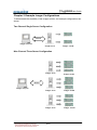
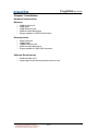
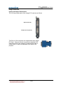
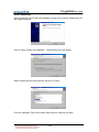
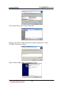
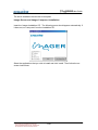
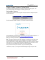
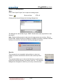
User Guide
User Guide
Version 1.41
1
User Guide
USE AND DISCLOSURE OF DATA
Imager™ is a trademark of Christie. All other products or brand names are trademarks of their
respective holders.
This product is licensed to Christie Digital by Equipe Electronics Ltd.
? 2003-2004 Equipe Electronics Ltd. All rights reserved. This document may not be reproduced or
distributed in any form, in whole or part, without the express written permission of Equipe Electronics
Ltd.
Issue / Amendment Record
Issue
Date
Pages / Comments
1v09
31 Oct 03
Software V1.09
1v41
30 Jan 04
Software V1.41
2
User Guide
Table of Contents
Chapter 1 Introduction ......................................................................7
Chapter 2 Example Imager Configurations....................................8
Two Channel Single Server Configuration.................................................................8
Nine Channel Three Server Configuration.................................................................8
Chapter 3 Installation ........................................................................9
Hardware Requirements ............................................................................................9
Minimum .................................................................................................................9
Recommended .......................................................................................................9
Software Requirements .............................................................................................9
Imager Hardware......................................................................................................10
Input and Output Connectors ...............................................................................10
Driver Installation ..................................................................................................11
Imager Server and Imager Composer Installation...................................................13
Chapter 4 Imager Composer: Getting Started .............................14
Starting Imager Composer.......................................................................................14
Project File Management .........................................................................................15
Open .....................................................................................................................15
Save As .................................................................................................................15
Save ......................................................................................................................16
Channel List Management .......................................................................................17
Manually Adding a Channel..................................................................................17
Automatically Adding Channels............................................................................19
Navigating Between Channels .................................................................................22
The Channel Toolbar................................................................................................23
Mapping.................................................................................................................23
Blending ................................................................................................................23
Hotspot Compensation .........................................................................................23
Fast Update...........................................................................................................23
Colour Adjustment ................................................................................................23
Tracking & Phase .................................................................................................23
Channel Function Toggle......................................................................................24
Channel Colour Toggle.........................................................................................24
Channel Refresh...................................................................................................24
The Global Toolbar...................................................................................................24
Edge Blend Grouping............................................................................................24
Global Function Toggle.........................................................................................25
Global Colour Toggle............................................................................................25
Fast Update...........................................................................................................25
Light Level.............................................................................................................25
Save/Load from Server.........................................................................................25
The Channel Status Window ...................................................................................26
The Messages Window............................................................................................26
Tracking & Phase Adjustment .......................................................27
Steps to Adjust Tracking and Phase........................................................................27
Vertical Delay Lines..................................................................................................27
Colour Adjustment...........................................................................28
Colour Adjustment Interface.....................................................................................28
Selecting Colour....................................................................................................28
Adjusting Colour....................................................................................................28
Resetting To Defaults ...........................................................................................28
Dynamic Light Level Controls...............................................................................28
3
User Guide
Input and Output Gamma ........................................................................................28
Mapping in Detail .............................................................................29
Overview...................................................................................................................29
User Interface...........................................................................................................30
Creating a New Mesh...........................................................................................30
Control Point Manipulation....................................................................................30
Tangent Vector Manipulation................................................................................31
Zooming ................................................................................................................31
Panning .................................................................................................................32
Mesh Progression.................................................................................................32
Render Options.....................................................................................................32
Vertical Delay Lines ..............................................................................................33
Mapping Masking..................................................................................................33
Mapping Data Import ............................................................................................34
Edge Blending in Detail...................................................................38
Overview...................................................................................................................38
Defining Blend Geometry.........................................................................................39
Aligning with Distortion Correction Mesh .............................................................39
Zooming ................................................................................................................39
Panning .................................................................................................................39
Creating a Parent Spline.......................................................................................39
Manipulation of Parent Spline Control Points ......................................................40
Creating Child Splines ..........................................................................................41
Manipulation of Child Spline Control Points .........................................................41
Spline Selection ....................................................................................................42
Tangent Vectors ...................................................................................................42
Working with Multiple Blends................................................................................42
Adjusting Blend Gradient..........................................................................................43
Blend Grouping .....................................................................................................43
Blend Direction......................................................................................................45
Adjusting the Blend Gradient................................................................................46
Adjusting Blend Gamma and Curve via External Light Level Input.....................48
Edge Blend Masking ................................................................................................48
Importing Blend Data................................................................................................49
Hotspot Compensation in Detail....................................................52
Overview...................................................................................................................52
User Interface...........................................................................................................52
Colour Channel Selection .....................................................................................52
Hotspot Manipulation ............................................................................................52
Display Options.....................................................................................................54
Importing Hotspot Data.........................................................................................54
Chapter 10 Light Level ....................................................................56
Overview...................................................................................................................56
Key-framing ..............................................................................................................56
Interface Protocol .....................................................................................................57
Chapter 11 The Imager Server .......................................................59
Debug Viewer...........................................................................................................59
Packet Debug .......................................................................................................60
Channel Debug .....................................................................................................60
Saving and Loading ..............................................................................................60
Chapter 12 Appendix A: Imager Composer Short-cut Keys .....61
Mapping Short-cut Keys ...........................................................................................61
Blending Short-cut Keys...........................................................................................61
4
User Guide
Hotspot Compensation Short-cut Keys ...................................................................61
Chapter 13 Appendix B: Example Channel Configuration Files63
SGI IR2.....................................................................................................................63
NVidia Geforce 2/3/4 ................................................................................................63
5
User Guide
Chapter 1 Introduction
Christie Imager enables the use of digital projection on curved displays, replacing
traditional specialist simulation CRT projector functions for mapping, blending and
shading.
Mapping
Christie Imager applies an advanced digital filter technique to eliminate aliasing effects
that can be caused by mapping pixels to a new position. Mapping is defined by a mesh
pre-calculated to match the optical geometry. It may then be finely adjusted for precise
alignment to the pilot's eye position.
Blending
Where two images overlap, a blend region is defined
where one projector fades out as another fades in.
Using digital techniques this blend region is almost
imperceptible to the observer as the correct proportion
from each projector is precisely calculated.
Hotspot Compensation
Independent digital shading of each colour plane provides the means to compensate
for colour shifts between projectors and colour variations within each projector field.
Compensation for shading variations within curved dome displays and back projection
hotspots can also be pre-calculated and removed by loading into the Imager shading
system.
Scalable Client/Server Architecture
Up to three Imager PCI cards can be contained within a PC. This number can be
increased up to 32 channels by adding more servers to the network. All channels on
the network can then be controlled via Imager Composer.
This document is confidential to and the sole
property of Equipe Electronics Ltd., and should not
be reproduced or disclosed without permission
7-64
User Guide
Chapter 2 Example Imager Configurations
To demonstrate the scalability of the Imager solution, two example configurations are
shown.
Two Channel Single Server Configuration
Network
Imager Composer
Imager Server
Imager
PCI HW
Nine Channel Three Server Configuration
Imager Server
Imager PCI HW
Imager Server
Imager PCI HW
Imager Server
Imager
Network
Imager Composer
This document is confidential to and the sole
property of Equipe Electronics Ltd., and should not
be reproduced or disclosed without permission
8-64
PCI HW
User Guide
Chapter 3 Installation
Hardware Requirements
Minimum
?
?
?
?
?
350MHz Pentium II
64Mb RAM
10Mb Ethernet Card
50Mb free hard disk space
Display capable of 1024x768 resolution.
Recommended
?
?
?
?
?
2GHz Pentium 4
256Mb RAM
100Mb Ethernet Card
50Mb free hard disk space
Display capable of 1280x1024 resolution.
Software Requirements
?
?
Windows 2000 or XP
Large swap file (double the physical memory size)
This document is confidential to and the sole
property of Equipe Electronics Ltd., and should not
be reproduced or disclosed without permission
9-64
User Guide
Imager Hardware
Input and Output Connectors
The VGA input and output of the Imager PCI card are as follows:
Input (From IG)
Output (To Projector)
Two DVI to VGA converters are supplied with each Imager
PCI Card. Use one of these to connect a standard VGA
cable from an IG to the Imager PCI card and the other to
connect the PCI card via a standard VGA cable to the
projector.
This document is confidential to and the sole
property of Equipe Electronics Ltd., and should not
be reproduced or disclosed without permission
10-64
User Guide
Driver Installation
On the server PC, the ‘Found new Hardware’ wizard can be used to install drivers for
the Imager hardware.
Click on ‘Next’ to begin the installation. The following menu will appear:
Select ‘Display a list of known drivers’ and click on ‘Next’.
From the ‘Hardware Type’ menu select ‘Other devices’ and click on ‘Next’.
This document is confidential to and the sole
property of Equipe Electronics Ltd., and should not
be reproduced or disclosed without permission
11-64
User Guide
In the ‘Select a driver menu’ click on ‘Have Disk’.
Browse to the ‘Drivers’ folder located on the Imager Installation CD. Select
‘PCISDK.inf’ and click on ‘Open’.
Select ‘Christie Imager Board v1.0’ and click on ‘Next’.
This document is confidential to and the sole
property of Equipe Electronics Ltd., and should not
be reproduced or disclosed without permission
12-64
User Guide
The driver installation should now be complete.
Imager Server and Imager Composer Installation
Insert the ‘Imager Installation CD’. The following menu should appear automatically. If
it does not, run ‘setup.exe’ from the installation CD.
Select the applications that you wish to install and click ‘Install’. Then follow the onscreen instructions.
This document is confidential to and the sole
property of Equipe Electronics Ltd., and should not
be reproduced or disclosed without permission
13-64
User Guide
Chapter 4 Imager Composer: Getting Started
The following section describes how to manage a Imager Composer project. This
covers saving, loading and managing of channel (projector) lists.
Starting Imager Composer
To start Imager composer, select ‘Programs->Imager Composer->Imager Composer’
from the start menu.
On initial loading of Imager composer, the following message will appear:
This indicates that no license has been installed for your copy of Imager Composer. To
get a trial or permanent license email [email protected]
stating your machine identification (shown above in red text).
Note: If the error ‘Failed to get valid MAC address’ is displayed, the most likely cause
is that the NetBIOS protocol has not been installed on your machine. Contact your
network administrator for details regarding installation of the NetBIOS protocol. Another
cause may be if one of your network interfaces is enabled but not connected to a LAN.
In this case you should disable this interface in the Device Manager.
Once you have received your license file, copy it to the following folder.
<Install Drive (usually ‘C:’)>/Program Files/Christie Digital /Imager Composer /bin/
This document is confidential to and the sole
property of Equipe Electronics Ltd., and should not
be reproduced or disclosed without permission
14-64
User Guide
Project File Management
Open
Click on the ‘Open Project’ icon to open an existing project.
Toolbar:
Short-cut Keys:
CTRL+O
Clicking on the icon will display the following dialogue box:
The dialogue box will list files of type *.EMB. Double-click on the required file to load
the project.
Note: Before loading a project, make sure all Imager servers are running. When a
project loads, Imager composer will attempt to establish a network connection with the
server(s). If a server is not online the following message will appear:
Save As
This command is not accessible via the toolbar or a short cut.
Instead, it must be executed from the File menu at the top of the
screen.
This command allows you to choose the filename you want to save
project file as and the directory you want to save it to. The following
dialogue box will appear in order for you to carry out this function:
This document is confidential to and the sole
property of Equipe Electronics Ltd., and should not
be reproduced or disclosed without permission
15-64
User Guide
Save
This command will save the current project to its current filename and directory.
Executing this command for the first time will instead execute the ‘Save as’ command
(see above).
Toolbar:
Short-cut Keys:
This document is confidential to and the sole
property of Equipe Electronics Ltd., and should not
be reproduced or disclosed without permission
16-64
CTRL+S
User Guide
Channel List Management
The channel list is displayed on the top-left of the screen.
Initially, this list will be empty. The section below
describes how to add channels to the active project using
a manual and automated method.
Manually Adding a Channel
Click on the toolbar icon shown below to add a channel to the active project manually.
Toolbar:
Short-cut Key:
F3
Clicking on the aforementioned icon will display the following menu:
Each of the fields related to the ‘Add Channel’ menu are explained below.
Dummy Channel:
Select this check-box if you wish to add a ‘dummy’ channel. A dummy channel does
not attempt to make a connection to a Imager server and is thus useful for using
Imager Composer standalone.
Local Host:
Select this check-box if you have Imager Server and Imager Composer running on the
same machine.
Server Name/IP:
If Imager Server is running on a remote machine, enter the host name or alternatively
the IP address of the Imager server.
If you are adding a ‘dummy’ channel, leave this blank.
This document is confidential to and the sole
property of Equipe Electronics Ltd., and should not
be reproduced or disclosed without permission
17-64
User Guide
PCI Slot:
Select from the pull down menu the PCI slot to which the channel’s Imager PCI Card is
inserted in this field. This can be found by inspecting the Imager server’s Debug
viewer (Discussed in Section 11 – ‘Imager Server’). If the channel is ‘dummy’, this field
can be left blank.
Channel ID:
Assign a unique ID to the channel in this field. This ID is necessary to help you
differentiate between channels in your channel list. Therefore, a logical arrangement of
channel ID’s is preferable (e.g. from left to right).
Configuration:
Select the channel format parameters configuration from this list. Each configuration
corresponds to a file located under:
<Imager Composer Install Directory>/ChannelSetup
For more information regarding channel configuration files, see Appendix B.
Note: An invalid channel configuration selection will result in a blank image.
Rotation
Channel rotation can be set to 0, 90, 180 or 270 degrees. This feature simplifies
mapping and blending adjustments when working with rotated projectors.
0 degree rotation (default)
90 degree rotation
Description
Optional field for a general channel description.
Adding the Channel
Once the aforementioned fields have been completed, add the channel by clicking on
the ‘Add Channel’ button.
If connection to the Imager server is successful the channel will appear in the channel
list at the top-right of the screen.
This document is confidential to and the sole
property of Equipe Electronics Ltd., and should not
be reproduced or disclosed without permission
18-64
User Guide
If a connection is not established, an error message will occur and the channel will not
be added to the channel list. There are a number of likely causes for this:
1. The server IP or hostname has been mistyped. Try re-typing the server hostname
or IP address.
2. The Imager server is not running on the designated PC. Verify that this is not the
case.
3. The PC on which the Imager server is running is not connected via the Ethernet to
the same PC that is running the Imager Composer.
4. An incorrect PCI slot has been selected. Verify that on the Imager Server debug
viewer, a Imager PCI card has been assigned the required PCI slot.
Automatically Adding Channels
The preferable way of adding channels to the channel list is with the ‘Channel Scan’
feature.
Clicking on the following toolbar icon will display the ‘Channel Scan’ menu.
Toolbar:
The ‘Channel Scan’ menu:
The Channel Scan menu will scan the network for all available channels. To begin a
scan, click on the ‘Scan Network for Channels’ button. After a few seconds, a list of
one or more channels should appear in the ‘Channels Found’ list.
To add a channel to the active channel list, highlight the appropriate channel from the
‘Channels Found’ list and click the top arrow to move the channel to the ‘Current
Channels’ list.
Select the channel format from the drop-down menu located above the current
channels list. The format will be applied to all channels which are added.
Now click on ‘OK’. The selected channels will now initialise and will be shown in the
channel list located in the top-left of the screen.
This document is confidential to and the sole
property of Equipe Electronics Ltd., and should not
be reproduced or disclosed without permission
19-64
User Guide
Note: When adding channels using the automated method, the channel configuration
will still need to be selected for each channel. Before this is done, the output from the
Imager PCI cards will be blank.
This document is confidential to and the sole
property of Equipe Electronics Ltd., and should not
be reproduced or disclosed without permission
20-64
User Guide
To select the correct channel configuration, select each channel from the channel list
drop-down menu and click on the channel setup icon:
Toolbar:
Short-cut Key: F2
Clicking on the icon will display the following menu:
Select from here the desired channel configuration file. Refer to Appendix B for
additional information regarding channel configuration files.
This document is confidential to and the sole
property of Equipe Electronics Ltd., and should not
be reproduced or disclosed without permission
21-64
User Guide
Navigating Between Channels
Imager Composer enables you to control up to 32 channels. To edit a channel, select
it from the drop-down channel list.
After a channel has been selected from the list, all channel function icons (shown
above) will apply to that individual channel. The channel toolbar is discussed in detail
in the following section.
When a channel is selected from the list windows corresponding to the previously
selected channel are NOT closed. This allows for the simultaneous editing of any
number of channels. The image below demonstrates this.
Editing mapping for two channels simultaneously
This document is confidential to and the sole
property of Equipe Electronics Ltd., and should not
be reproduced or disclosed without permission
22-64
User Guide
The Channel Toolbar
Mapping
Clicking on the mapping icon will display the distortion correction menu for the currently
selected channel. See section 7 for more information regarding mapping.
Toolbar:
Short-cut Key:
F5
Blending
Clicking on the below icon will display the Edge Blending menu for the currently
selected channel. See section 8 for more information regarding edge blending.
Toolbar:
Short-cut Key:
F6
Hotspot Compensation
Clicking on the below icon will display the Hotspot Compensation menu for the
currently selected channel. See section 9 for more information regarding hotspot
compensation.
Toolbar:
Short-cut Key:
F7
Fast Update
The ‘Fast Update’ feature enables faster downloading of mapping data and blending
data to the Imager PCI hardware. However, the screen will go blank during the update
period with this feature enabled.
‘Fast update’ is enabled by default. Un-checking the option will provide non-disruptive
(but slower) adjustments of mapping and blending.
Toolbar:
Colour Adjustment
Clicking on the below icon will display the colour adjustment menu for the currently
selected channel. See section 6 for more information regarding colour adjustment.
Toolbar:
Short-cut Key:
F8
Tracking & Phase
Clicking on the below icon will display the tracking and phase menu for the currently
selected channel. See section 5 for more information regarding tracking and phase.
Toolbar:
This document is confidential to and the sole
property of Equipe Electronics Ltd., and should not
be reproduced or disclosed without permission
23-64
User Guide
Channel Function Toggle
Toggles mapping, edge blending and hotspot compensation functions for the selected
channel.
Toolbar:
Short-cut Keys (respectively): CTRL+F5, CTRL+F6, CTRL+F7
Channel Colour Toggle
Toggles red, green and blue colour channels for the selected channel.
Toolbar:
Short-cut Keys (respectively): CTRL+F1, CTRL+F2, CTRL+F3
Channel Refresh
Mapping, blending, hotspot compensation and colour
balance can be refreshed for the currently selected from
the channel drop-down menu located at the top of the
screen.
Performing a Composer Refresh will cause Imager
Composer to re-send data to the mapping server. This
is useful in the event of a communications failure
between Imager Composer and Imager server.
Performing a server refresh will instruct Imager
Server(s) to refresh the Imager hardware directly. This
is faster than the Composer Refresh.
Short-cut Keys:
Composer Refresh:
SHIFT+CTRL+F9
Server Refresh:
F12
Toolbar:
The Global Toolbar
The global toolbar (shown below) applies to all channels contained in the active project.
Edge Blend Grouping
Clicking on the below icon will display the Edge Blend Grouping menu. For more
information regarding edge blend grouping refer to Section 8 - ‘Edge Blending In
Detail’.
Toolbar:
Short-cut Key:
This document is confidential to and the sole
property of Equipe Electronics Ltd., and should not
be reproduced or disclosed without permission
24-64
F4
User Guide
Global Function Toggle
The global function toggle icons will enable or disable a mapping, blending or hotspot
compensation for every channel contained in the active project.
Toolbar:
Global Colour Toggle
This toggles red, green and blue colour channels for all channels contained in the
active project.
Toolbar:
Fast Update
The fast update checkbox located in the Global menu will set the fast update mode for
all channels contained in the current project.
Toolbar:
Light Level
Under operating conditions light level input would be sent from an external machine
such as an Image Generator. Here, a light level facility is provided for testing
purposes.
Setting the light level can affect edge blends and colour balance. See sections 8 and 6
respectively for information on how to configure this.
A detailed explanation outlining the use of light level input is given in Section 10.
Toolbar:
Save/Load from Server
The Imager server does not require a connection to Imager
Composer in order to function under normal operating
conditions. In order for the Imager Server(s) to function
standalone post-setup, the project data must be saved locally
on each server.
This can be achieved from Imager Composer from the ‘global’
drop-down menu located at the top of the screen.
This document is confidential to and the sole
property of Equipe Electronics Ltd., and should not
be reproduced or disclosed without permission
25-64
User Guide
The Channel Status Window
The channel status window is located at the bottom-left of the main menu. This menu
contains the status of all channels assigned to the current project.
Information given for each channel within this menu includes:
Channel ID: The unique identification number of the channel.
Video Format: The filename of the video format used for the channel.
Status: Tells us when the channel is busy (processing and updating) or ready for
further editing.
Server: The IP address or hostname of the computer where the Imager PCI hardware
is located.
Slot number: The PCI slot number that the Imager PCI hardware is plugged in to.
The Messages Window
The messages window is located at the bottom-right of the main window. This window
displays info messages produced by ProMap Composer. This includes information
regarding communication between Composer and Server(s) in addition to warning and
error messages.
This document is confidential to and the sole
property of Equipe Electronics Ltd., and should not
be reproduced or disclosed without permission
26-64
User Guide
Chapter 5 Tracking & Phase Adjustment
Under normal circumstances the first task undertaken will be the setup of channel
tracking and phase.
Tracking and Phase menu:
Steps to Adjust Tracking and Phase
Below are the recommended steps to configure tracking and phase.
1. Connect the Imager VGA output directly to a CRT monitor and NOT to a projector.
This step will eliminate any tracking and phase issues with the projector.
2. Load a test pattern on the machine connected to the Imager VGA input (normally
an Image Generator). The test pattern must incorporate many vertical lines, each of
one pixel width. The image below shows a pre tracking-adjusted test pattern
3. Adjust the tracking until the test image has clear and distinct black lines (as below).
4. Make fine adjustments with Phase.
5. Connect the Imager VGA output to the projector and repeat the above steps with
the projector remote control (NOT with Imager Composer).
Vertical Delay Lines
Vertical Delay lines should initially be set to a high value (a value of 300 is sufficient in
most cases). For more information regarding this property refer to Section 7 –
‘Mapping in Detail’.
This document is confidential to and the sole
property of Equipe Electronics Ltd., and should not
be reproduced or disclosed without permission
27-64
User Guide
Chapter 6 Colour Adjustment
The colour adjustment menu provides control of the
following colour properties:
?
?
?
?
?
Scale
Offset
Input Gamma
Output Gamma
Gain
A common interface is used for each of the above
properties. The interface is explained in detail
below.
Colour Adjustment Interface
Selecting Colour
Each of the three primary colours can be adjusted independently by
selecting the colour in the ‘RGB Select’ frame.
Optionally, ‘All’ can be selected to adjust all three colours
simultaneously.
Adjusting Colour
A slider allows the colour to be adjusted by dragging the pointer. Alternatively, the
keyboard cursor keys can be used to move the pointer once the slider has been
selected.
Resetting To Defaults
The default value of the colour property can be set by clicking on the ‘Defaults’ button
located to the top-left of the menu.
Dynamic Light Level Controls
See Section 10 – ‘Light Level Input’.
Input and Output Gamma
To achieve optimal blending it is first necessary to correctly set the input (IG)
and output (Display) gammas for each channel.
Please refer to your IG and Projector documentation in order to find out the appropriate
values of input and output gamma.
This document is confidential to and the sole
property of Equipe Electronics Ltd., and should not
be reproduced or disclosed without permission
28-64
User Guide
Chapter 7 Mapping in Detail
Overview
Imager Composer provides a WYSIWYG (What you see is what you get) interface to
adjust the mapping from the non-distorted input image to the output image.
Geometry correction adjustment is performed using a mesh, which is defined using a
set of control points.
Output Image
Imager Composer
The number of control points used varies with the application. For a flat screen, 2x2
control points are often sufficient. For a spherical screen, more control points may be
necessary to accurately represent the geometry correction. Imager Composer supports
up to 20x20 control points.
2x2 Control Points
9x9 Control Points
Imager Composers distortion correction mesh also supports the use of tangent vectors.
Tangent vectors define the mesh between adjacent control points (see below).
Input Image
This document is confidential to and the sole
property of Equipe Electronics Ltd., and should not
be reproduced or disclosed without permission
Tangent Vector Adjustment
29-64
Output Image
User Guide
Tangent vectors provide a higher level of flexibility for distortion correction. However,
they are optional as Imager Composer can automatically calculate them.
Generally tangent vectors are especially useful during the final stages of setup for finetuning.
User Interface
Creating a New Mesh
When a new channel has been added to the active project, its default number of control
points defining the distortion correction mesh is 3x3 control points. To create a mesh
of any number of control points, click on the ‘New Mesh’ button located in the left
menu.
The following window will appear:
To create the new mesh, enter the desired number of vertical and horizontal control
points and click ‘OK’.
Control Point Manipulation
Selecting a Control Point
To select a control point with the mouse, click on the desired control
point with the left mouse button. The control point selected will
display as a highlighted ring.
To select a control point with the keyboard, use the cursor keys to move the control
point selection horizontally and vertically.
Note: To use the keyboard short-cut keys, the mesh needs to be focused. To focus the
mesh, click the cursor in the mesh window or press CTRL+F.
Selecting Multiple Control Points
To select multiple control points, click and drag over the desired points whilst holding
the left mouse button. A black box will be displayed over the selected region. When
the left mouse button is released, the control points will display as highlighted rings.
This document is confidential to and the sole
property of Equipe Electronics Ltd., and should not
be reproduced or disclosed without permission
30-64
User Guide
Moving Selected Control Points
To move a selection of control points click and drag with the left mouse button held
down.
For precise movement of selected control points it is recommended that the keyboard
short-cut keys be used.
Three levels of precision are possible using the keyboard short-cut keys:
1. Large movement (35 pixels): ALT + Cursor Keys
2. Medium movement (10 pixels): Ctrl + Cursor Keys
3. Small movement (1 pixel): Shift + Cursor Keys
Tangent Vector Manipulation
By default, auto tangent vectors are enabled. When auto
tangent vectors are enabled, it is not possible to
manipulate tangent vectors.
To disable auto tangent vectors, uncheck the ‘Auto Tangent
Vectors’ and check the ‘Show Tangent Vectors’ options on the left
menu. The tangent vectors should now be visible.
Selecting a Tangent Vector
To select a tangent vector with the mouse, click on the tangent
vector with the left mouse button. The tangent vector handle will
now be highlighted.
To select a control point with the keyboard, use the cursor keys to
move the tangent vector selection horizontally or vertically. To
toggle between the selection of vertical or horizontal tangent vector handles, use the
‘CTRL + H’ short cut key.
Horizontal Tangent
Vector Handle
Vertical Tangent
Vector Handle
Moving a Tangent Vector
See ‘Moving Selected Control Points’.
Zooming
There are a number of ways to zoom in and out in the mesh window:
? If you are using a mouse with a scroll button, scroll up to zoom in and scroll down
to zoom out.
This document is confidential to and the sole
property of Equipe Electronics Ltd., and should not
be reproduced or disclosed without permission
31-64
User Guide
?
?
?
Select the zoom level from the drop-down list menu,
which is situated at the bottom left of the window.
Right-click in the mesh window to display the context
sensitive menu (shown to the right).
Use the ‘CTRL + +’ and ‘CTRL + -‘ short-cut keys.
Panning
When using a high zoom level, it may be necessary to pan around the mesh. To do
this, right click and drag in the mesh window to pan.
Mesh Progression
The number of horizontal and vertical control points forming a mesh can be gradually
increased using the mesh progression feature.
During initial adjustments of the mesh, it is often preferable to start with a low amount
of control points. However, it is not always possible to achieve a perfect result with a
low number of control points. This is due to factors including imperfections with the
projection surface.
When more mesh detail is required, increase the
number of horizontal or vertical control points using
the mesh progression drop down menu (shown right).
Original Mesh
(5x4 control points)
Mesh after progression
function has been applied.
(13x10 control points)
Note: If mesh progression is accidentally applied, restore your original mesh by clicking
‘undo’.
Render Options
Show Selected Point Option
The ‘Show Selected Point’ option can be enabled to
display the position of the selected point on the output
image. The selected point will be represented as a
white cross-hare.
This document is confidential to and the sole
property of Equipe Electronics Ltd., and should not
be reproduced or disclosed without permission
32-64
User Guide
High Detail Render
Increased geometrical accuracy can be obtained by enabling the ‘High Detail Render’
option, though in practise the difference may be negligible.
Note: A high detail render can often take up to 10 seconds to complete. It therefore
should only be enabled during the very final stages of mesh geometry adjustment.
Vertical Delay Lines
The value of vertical delay lines should be set to the maximum distance between the
bottom of a channel and the bottom row of mesh control points (shown below as D).
The value for vertical delay lines can be set from
the Tracking and Phase menu.
By default, the value for vertical delay lines is
set to 300. This is sufficient for most mapping
configurations.
However, there is an increase in latency from
image input to image output with higher vertical
delay line values. Therefore it is recommended
that an optimum value be found once geometry
correction has been finalised.
D
As an aid to finding the optimum vertical delay lines value, Imager Composer can
estimate the value.
To adjust the value for vertical delay lines click on the icon shown to the right
to display the Tracking and Phase window. Click on ‘Estimate’ to the right of
the Vertical Delay Lines input box to estimate the optimum value of vertical delay lines.
Note: If the value for vertical delay lines is too small, artefacts may appear in the output
image.
Mapping Masking
Mapping masking ensures that a black border is displayed around the mapped output
image.
This document is confidential to and the sole
property of Equipe Electronics Ltd., and should not
be reproduced or disclosed without permission
33-64
User Guide
Mapping Masking Disabled
Mapping Masking Enabled
By default, mapping masking is disabled. This should be enabled once the geometry
correction process is nearing completion in order to avoid confusion during alignment
of the mesh extents.
To enable mapping masking, click on the ‘Setup’ button located in the ‘Masking’ frame
of the mapping menu.
The window shown to the right will be displayed. Check the
‘Mapping Mask’ option and click ‘Update Mask’.
The mapping mask can be quickly updated from the mapping menu
in a number of ways:
1. Click the ‘Update’ button located in the ‘Masking’ frame of the mapping menu.
2. Use the short-cut key CTRL+M.
3. Right-click in the mesh window to display the context sensitive menu (see right) and
select ‘Update Mask’.
Mapping Data Import
Import Format
Geometry correction data may be imported from an external application such as a
spreadsheet. Imported data must be of the following format:
Line No.
1
2
3
4
5
6
7
8
...
Data
<Number of control points H>;< Number of control points V>;
<Point 0 x>;<Point 0 y>;
<Point 1 x>;<Point 1 y>;
<Point 2 x>;<Point 2 y>;
<Point 3 x>;<Point 3 y>;
<Point 4 x>;<Point 4 y>;
<Point 5 x>;<Point 5 y>;
<Point 6 x>;<Point 6 y>;
<Point n x>;<Point n y>;
Line 1 states the number of horizontal and vertical control points.
Lines 2 – 6 state the co-ordinates of the first horizontal row of control points.
Lines 7 – 11 state the co-ordinates of the second horizontal row of control points.
All numbers are separated with the delimiter ‘;’.
This document is confidential to and the sole
property of Equipe Electronics Ltd., and should not
be reproduced or disclosed without permission
34-64
User Guide
Control point co-ordinates are ordered from left to right, top to bottom order.
Mapping import file should have the file extension ‘.map’.
This document is confidential to and the sole
property of Equipe Electronics Ltd., and should not
be reproduced or disclosed without permission
35-64
User Guide
Example Import Data for a 5x4 Mesh:
5;4;
28;158;
324;39;
671;-30;
1009;-31;
1282;10;
111;501;
385;402;
705;329;
1016;297;
1271;296;
239;799;
487;722;
763;652;
1030;598;
1255;563;
371;1022;
590;959;
822;894;
1045;833;
1240;781;
2
3
1
4
0
8
7
9
6
5
13
14
12
11
10
19
18
17
16
15
Import Interface
Import geometry correction data by clicking ‘Import Data’ in the mapping menu.
The following dialogue box will appear:
Navigate to the file location and double-click on the file to import.
When the geometry correction mesh has been imported
successfully, the import filename will appear in the
import frame (see right).
If any external changes are made to the import file, they
This document is confidential to and the sole
property of Equipe Electronics Ltd., and should not
be reproduced or disclosed without permission
36-64
User Guide
can be reloaded at any time by clicking ‘Reload Import’.
This document is confidential to and the sole
property of Equipe Electronics Ltd., and should not
be reproduced or disclosed without permission
37-64
User Guide
Chapter 8 Edge Blending in Detail
Overview
Imager composers edge-blending interface allows for the placing of blends arbitrarily
within the output image.
Output Image. No Blending
Apply Edge Blending
Output Image. With Blending
Blends are defined using a number of splines. Splines are smooth lines formed by a
number of control points, similar to that used for Imager Composers distortion
correction facility.
Initially, positioning of a blend is achieved using a single parent spline. The blend width
and shape is defined by two child splines, which are positioned either side of the
parent spline.
Parent Spline
Parent & Child Splines
The blend gradient is faded between the two child splines from 0% to 100%
opaqueness. The shape of the blend gradient is defined by a function of blend curve
and gamma (illustrated below).
Blend Curve = 0.5
+
Blend Gamma = 1.6
This document is confidential to and the sole
property of Equipe Electronics Ltd., and should not
be reproduced or disclosed without permission
38-64
User Guide
Defining Blend Geometry
Aligning with Distortion Correction Mesh
To aid with the alignment of edge blends to the distortion mesh edges, it is often helpful
to display the distortion mesh in the Edge Blend Adjustment window.
To enable this option, click ‘Show Distortion Mesh’.
Edge blend menu showing ‘ghosted’
distortion correction mesh.
Zooming
There are a number of ways to zoom in and out in the blend window:
? If you are using a mouse with a scroll button, scroll up to zoom in and scroll down
to zoom out.
?
Select the zoom level from the drop-down list menu to
the bottom left of the window.
?
Right-click in the mesh window to display the context sensitive
menu (see right).
?
Use the ‘CTRL + +’ and ‘CTRL + -‘ short-cut keys.
Panning
When using a high zoom level it may be necessary to pan around the mesh. Right
click and drag in the mesh window to pan.
Creating a Parent Spline
To create a new parent spline click on the ‘New Spline’ button located near the top of
the edge blend menu.
Note: When only the parent spline exists, the blend will not be visible on the output
image. Once the child splines have been created, the blend
will be visible.
The parent spline will be positioned initially in the centre of
the channel and orientated vertically.
This document is confidential to and the sole
property of Equipe Electronics Ltd., and should not
be reproduced or disclosed without permission
39-64
User Guide
Two control points are used by default to form a straight blend. Under normal
circumstances, this is a sufficient number of control points for cylindrical and flat
displays.
If two control points are not sufficient, use the ‘Number of
Control Points’ drop down menu (see right) at any time during
adjustment of the edge blend.
Note: It is recommended that 2 to 3 control points be used for initial positioning and
shaping of the blend. The number of control points can later be increased when more
accuracy is required.
Manipulation of Parent Spline Control Points
To select a control point with the mouse, click on the desired point
with the left mouse button. The control point will display as a
highlighted ring (see right).
To select a control point with the keyboard, use the cursor keys to move the point
selection horizontally and vertically.
Note: To use the keyboard short-cut keys, the mesh needs to be focused. To focus the
mesh, click the cursor in the mesh window or press CTRL+F.
Selecting Multiple Control Points
To select multiple control points, click and drag over the desired control points whilst
holding the left mouse button. A black box will be displayed over the selected region.
When the left mouse button is released, the control points will display as highlighted
rings.
Moving Selected Control Points
To move a selection of control points, click and drag pressing the left mouse button.
For precise movement of selected control points, it is recommended that the keyboard
short-cut keys be used.
Three levels of precision are possible using the keyboard short-cut keys:
4. Large movement (35 pixels): ALT + Cursor Keys
5. Medium movement (10 pixels): Ctrl + Cursor Keys
6. Small movement (1 pixel): Shift + Cursor Keys
This document is confidential to and the sole
property of Equipe Electronics Ltd., and should not
be reproduced or disclosed without permission
40-64
User Guide
When you are happy with the approximate position of the parent spline, the child
splines should be created.
Creating Child Splines
When the child splines are created, they are initially positioned perpendicular and equal
distance (D) to the parent spline.
The initial value of D can be set from the ‘Blend Width’ control.
The ‘Blend Width’ control
To create the two child splines click on ‘Split Parent Spline’.
D
Once the two child splines have been created, the blend will
be visible on the output image. Initially the blend will have no
gradient and instead will be rendered as with uniform 50%
intensity (see image to the right).
Manipulation of Child Spline Control Points
Once the two child splines have been created, they can be manipulated independently
of the parent spline.
Additionally, adjustments to the parent spline control point positions are mirrored by the
adjacent child spline control points (see below).
Moving a child spline control point
independently of the master spline:
Effect of moving a parent spline
control point on mirroring child spline
control points:
This document is confidential to and the sole
property of Equipe Electronics Ltd., and should not
be reproduced or disclosed without permission
41-64
User Guide
Spline Selection
The current spline selection is always highlighted in red. The mouse can be used to
select the spline. However, this method has the disadvantage of inadvertently moving
control points.
To cycle between the selected spline without moving a control point use one of the
following two methods:
?
Use the short-cut key ALT+ S.
?
Right click in the blend window to display the context sensitive
menu. Select ‘Cycle Spline Selection’.
Tangent Vectors
As is the case for distortion correction, edge blend splines use tangent vectors to
define the spline between two adjacent control points.
By default, auto tangent vectors are enabled. When auto tangent
vectors are enabled, it is not possible to manipulate tangent vectors.
To disable auto tangent vectors, uncheck the ‘Auto Tangent Vectors’
and check the ‘Show Tangent Vectors’ options on the left menu for the
required spline. The tangent vectors should now be visible.
Note: Tangent vector display and automation are toggled for each spline individually.
Selecting a Tangent Vector
To select a tangent vector with the mouse, click on the desired vector with the left
mouse button. The tangent vector handle will now be highlighted.
To select a tangent vector with the keyboard, you will first need to
switch to the tangent vector selection mode using the ‘CTRL + T’
short-cut key. You may then use the cursor keys to select the required
tangent vector handle.
Moving a Tangent Vector
See ‘Moving Selected Control Points’.
Working with Multiple Blends
When more that one blend has been assigned to a channel, one of
the following methods should be used to select an active blend for
adjustment:
?
Click with the mouse on a control point of the deactivated (grey) blend.
This document is confidential to and the sole
property of Equipe Electronics Ltd., and should not
be reproduced or disclosed without permission
42-64
User Guide
?
Use the ‘Select Blend’ drop-down menu (see right).
?
Use the ‘SHIFT + S’ short-cut key to cycle the blend selection.
?
Right click in the blend window to display the context sensitive
menu. Select the appropriate blend from the ‘Select Blend’ list
(see right).
Adjusting Blend Gradient
Blend Grouping
Blend curve and gamma is applied per blend group. Thus, an edge blend must be
assigned to a blend group before it can obtain a blend gradient. Any number of edge
blends can be assigned to a single blend group.
Blend groups should be shared between blends that overlap from neighbouring
channels.
Illustrated below is the process of setting up blend grouping for a two-channel
configuration:
Channel 0: Left
channel
Channel 1: Right
channel
Overlapping
Blends
Select the Edge Blend Grouping menu by clicking on the icon (see right) This
is located in the top toolbar.
Arrange the channels within the channel-grouping grid to approximate the positions of
the channels in relation to each other.
This is done by clicking on channel 0 (the left channel) within the
‘Channel’ frame (see right). The ‘Channel’ frame is located at the
top-left of the edge blend-grouping menu.
The channel will then appear within the centre of the edge
blend-grouping grid. Move the channel several grid squares to the left to leave room
for channel 1 (the right channel). Do this by clicking on the channel and dragging the
mouse cursor left.
This document is confidential to and the sole
property of Equipe Electronics Ltd., and should not
be reproduced or disclosed without permission
43-64
User Guide
Repeat the above step for channel 1. The edge blend-grouping grid should now look
similar to that shown below:
Now create a blend group. Do this by clicking on the ‘Add’ button within the ‘Group’
frame.
The following window will appear:
Enter a name for the blend group and optionally a blend description
and colour code. It is recommended that a colour code be used,
particularly if more that one blend group is to be used.
Click on ‘Add’ to add the blend group. The blend group will now
appear in the ‘Groups’ list shown on the left of the edge blendgrouping menu.
Now assign both edge blends to the newly created blend group. To
select the edge blends, first switch to ‘Edge Selection Mode’.
Switch to ‘Edge Selection Mode’ by first right clicking within the edge
blend-grouping grid. The context sensitive menu shown to the right
will appear. Now select ‘Edge Selection Mode’ from this menu.
To select the two edge blends, click on them with the left mouse
button so they are highlighted as shown below:
This document is confidential to and the sole
property of Equipe Electronics Ltd., and should not
be reproduced or disclosed without permission
44-64
User Guide
Edge blends selected in edge blend grouping menu.
Once the edge blends have been selected, display the
context sensitive menu with the right mouse button.
Move the mouse over the ‘Add Edge To Group’ item
(see right) and select the desired blend group from the
list displayed.
If the edge blends have been successfully assigned to the blend group, they will now
be colour coded in line with the blend group.
Edge blends successfully assigned to blend group and colour
coded accordingly.
Once the edge blends have been assigned to the edge blend group, the default linear
gradient will be applied.
Blend Direction
On initial set-up, the blend gradient direction of a blend may not be orientated correctly.
A blend must be orientated so that the 0% intensity side is located to the outer edge of
the channel. This is illustrated below:
Incorrect blend direction
This document is confidential to and the sole
property of Equipe Electronics Ltd., and should not
be reproduced or disclosed without permission
Correct blend direction
45-64
User Guide
To invert an edge blends gradient direction; select the ‘Invert
Blend Direction’ option for a selected edge blend in the edgeblending menu.
Adjusting the Blend Gradient
Please note that to achieve the optimal blend it is first necessary to correctly set
the input (IG) and output (Display) gammas for each channel. See chapter 6 for
more details of how to set input and output gamma.
If input and output gamma is configured then very little blend gamma adjustment
should be needed.
The blend curve and gamma menu discussed in this section can be accessed in either
of the two following ways:
1. From the Edge Blend Grouping menu, click on the desired blend group in the
‘Groups’ frame (pictured to the right) and then on the ‘Blend Curve’ button.
2. From a channels Edge Blending menu, select an edge blend. Now click on the
‘Blend Curve’ button located in the ‘Selected Spline’ frame. The Blend Curve
and Gamma window will then appear for the blend group for which the selected
blend is assigned.
Blend Gamma Menu
Blend Curve Menu
Blend Curve
The blend curve defines the severity of gradient between the 0% and 100% opaque
extents of the blend. Higher values of blend curve yield a more severe gradient.
Example blend curve values and the resulting blend gradients are given below.
A blend gamma of 1.0 is assumed for all samples.
This document is confidential to and the sole
property of Equipe Electronics Ltd., and should not
be reproduced or disclosed without permission
46-64
User Guide
Blend Curve = 0.0
Blend Curve = 1.0
Blend Curve = 4.0
The default value for blend curve is 0.0 (linear). In practise, a blend curve of higher
than 0.5 is not recommended. However, high blend curves are useful for matching the
centre line of overlapping edge blends.
Uniform 50/50 Blend Curve
A special case of blend curve is the 50/50 mode. This mode is
useful for alignment of overlapping blend edges.
When this option is enabled, the blend gradient is replaced by
a uniform 50% opacity.
It can be enabled by selecting the 50/50 option in the blend
curve menu.
Blend Gamma
Blend gamma is necessary to compensate for inconsistencies with different displays.
Example gamma values and the resulting blend gradients can be seen below.
A blend curve of 0.0 (linear) is assumed for all samples.
This document is confidential to and the sole
property of Equipe Electronics Ltd., and should not
be reproduced or disclosed without permission
47-64
User Guide
Blend Gamma = 1.0
Blend Gamma = 0.5
Blend Gamma = 1.5
Adjusting Blend Gamma and Curve via External Light Level Input
Varying degrees of input colour intensity affect the appearance of a blend. As a result
of this, most edge blends are optimised for a chosen colour intensity (i.e. in the daytime
and not at night with simulation applications).
With Imager Composer, it is possible to solve this problem by key-framing blend curve
and gamma at chosen light levels. This feature is discussed in more detail in Section
10 – ‘Light Level Input’.
Edge Blend Masking
Edge blends may not necessarily align exactly with the edge of the geometry correction
mesh. If this is the case, unwanted areas of 100% opacity can appear in the output
image (see illustration below).
100% Opacity
100% Opacity
No Blend masking
This document is confidential to and the sole
property of Equipe Electronics Ltd., and should not
be reproduced or disclosed without permission
48-64
User Guide
These areas can be masked using the Blend Masking facility.
Blend Masking Enabled
To enable blend masking, click on the ‘Setup’ button located in the
‘Masking’ frame of the Edge Blending menu.
The window shown to the right will be displayed. Check the ‘Blend
Mask’ option and click ‘Update Mask’.
The edge blend mask can be quickly updated from the edge
blending menu in a number of ways:
1. Click the ‘Update’ button located in the ‘Masking’ frame of the edge Blend
menu.
2. Use the short-cut key CTRL+M.
3. Right-click in the edge blend window to display the context
sensitive menu (see right). Select ‘Update Mask’.
Importing Blend Data
Edge blend control point position data may be imported for parent splines. After which,
the child splines may be created manually. Imported data must be of the following
format:
Data
<Number of control points for edge blend 0>;
<edge blend 0, control point 0 x>;<edge blend 0, control point 0 y>;
<edge blend 0, control point n x>;<edge blend 0, control point n y>;
<Number of control points for edge blend n>;
<edge blend n, control point 0 x>;<edge blend n, control point 0 y>;
<edge blend n, control point n x>;<edge blend n, control point n y>;
This document is confidential to and the sole
property of Equipe Electronics Ltd., and should not
be reproduced or disclosed without permission
49-64
User Guide
All numbers are separated with the delimiter ‘;’.
Up to 8 blends per channel can be imported.
Edge Blend import file should have the file extension ‘.edg’.
Example Import Data:
2;
50.0;0.0;
50.0;1024.0;
2;
1230.0;0.0;
1230.0;1024.0;
This document is confidential to and the sole
property of Equipe Electronics Ltd., and should not
be reproduced or disclosed without permission
50-64
User Guide
Import Interface
Import edge blend data by clicking ‘Import Data’ in the ‘Edge Blend’ menu.
The following dialogue box will appear:
Navigate to the file location and double-click on the filename to import.
When the edge blend data has been imported successfully, the name of the imported
file will appear in the Import frame.
If any external changes are made to the import file they can be reloaded at any time by
clicking ‘Reload Import’.
This document is confidential to and the sole
property of Equipe Electronics Ltd., and should not
be reproduced or disclosed without permission
51-64
User Guide
Chapter 9 Hotspot Compensation in Detail
Overview
Non-uniform colour discontinuities can sometimes occur with a projected image. This
can be as a result of factors such as refracted light and is especially common with
curved displays.
To solve this problem, Imagers Hotspot Compensation feature provides pixel level
control of colour scale.
Pre-compensated
Projected image.
Hotspot compensation
Post-compensated
Projected image.
User Interface
Colour Channel Selection
The colour channel can be independently edited by
selecting red, green or blue from the ‘RGB Select’
frame.
Alternatively, use the short-cut key Ctrl + 'R’ to cycle the colour channel selection.
Hotspot Manipulation
Hotspot Centre Selection
To select the centre of a hotspot with the mouse, click the desired
point within the hotspot grid with the left mouse button. The selected
point will then display as a white box.
To select a point with the keyboard, use the cursor keys to move the
point selection horizontally or vertically.
Note: To use the keyboard short-cut keys, the grid needs to be focused. To focus the
mesh, click the cursor in the grid window or press CTRL+F.
Adjusting Hotspot Intensity of a Selected Point
To increase the intensity around a selected point, click the left mouse button. To
decrease the intensity, click the right mouse button.
To increase the intensity around a selected point with the keyboard, use the ‘CTRL + +’
short-cut key. To decrease the intensity, use the ‘CTRL + -‘ short-cut key.
This document is confidential to and the sole
property of Equipe Electronics Ltd., and should not
be reproduced or disclosed without permission
52-64
User Guide
Note: The default intensity of all points is 100%. This value cannot be exceeded.
Therefore, initially only decreases in hotspot intensity are possible.
Radius of Influence
The radius of influence defines the area around the selected point for which the hotspot
is applied. The effect of the hotspot reduces linearly from the centre to the edges of
the area (illustrated below).
Radius of influence = 50
Radius of influence = 200
The radius of influence can be changed from the ‘Radius of Influence’ frame located to
the left of the ‘Hotspot’ menu.
Alternatively, the keyboard short-cut keys ‘Page Up’ and ‘Page Down’ can be used to
increase and decrease the radius of influence.
Increment
Alter ‘increment’ to increase or decrease the severity of a hotspot adjustment.
Increment = 0.5 (Single Adjustment)
Increment = 1.0 (Single Adjustment)
Altering Number of Grid Points
The default grid size is 21x21 points. This is sufficient for most applications. However,
it is possible to increase the number of grid points up to 100x100 points.
Using more grid points offers the advantage of a more accurate hotspot map. The
disadvantages are slight increase in render time and more cumbersome point selection
with the keyboard.
This document is confidential to and the sole
property of Equipe Electronics Ltd., and should not
be reproduced or disclosed without permission
53-64
User Guide
Display Options
Show All Colour Channels
Enabling this option displays the red, green and blue hotspot compensation maps
combined. This option is disabled by default.
Show Grid Points
Enabling this option displays the grid points overlaid on the hotspot maps. This option
is enabled by default.
Show Selected Point
Enabling this option displays the selected point on the output image as a white cross.
This option is disabled by default.
Importing Hotspot Data
Import Format
Hotspot compensation data may be imported from an external application such as a
spreadsheet. Imported data must be of the following format:
Data
<Number of grid points H>;< Number of grid points V>;
<Red Point 0 intensity>;
<Red Point n intensity>;
<Green Point 0 intensity>;
<Green Point n intensity>;
<Blue Point 0 intensity>;
<Blue Point n intensity>;
All numbers are separated with the delimiter ‘;’.
Intensity values should be in the range 0.0 to 1.0.
Grid point intensities are ordered from left to right, top to bottom.
Hotspot import file should have the file extension ‘.hot’.
Example Import Data for a 2x3 grid:
2;3;
1.0;
1.0;
-1.0;
1.0;
1.0;
-1.0;
1.0;
1.0;
1.0
1.0
1.0;
1.0;
Red Channel Import Data. (Green and blue are
uniform)
This document is confidential to and the sole
property of Equipe Electronics Ltd., and should not
be reproduced or disclosed without permission
54-64
User Guide
1.0;
1.0;
1.0;
1.0;
1.0;
1.0;
Import Interface
Import hotspot compensation data by clicking ‘Import Data’ in the ‘Hotspot’ menu.
The following dialogue box will appear:
Navigate to the file location and double-click on the file to import.
When the hotspot compensation data has been imported
successfully, the import filename will appear in the import
frame (see right).
If any external changes are made to the import file they can be reloaded at any time by
clicking ‘Reload Import’.
This document is confidential to and the sole
property of Equipe Electronics Ltd., and should not
be reproduced or disclosed without permission
55-64
User Guide
Chapter 10 Light Level
Overview
Imagers light level facility allows for real-time adjustment of many properties via a lightlevel value received via a UDP interface.
The properties supported by the light level feature are:
?
?
?
?
?
?
?
Blend Curve
Blend Gamma
Colour Scale
Colour Offset
Colour Input Gamma
Colour Output Gamma
Colour Gain
The value for light level ranges from 0% to 100% intensity.
Key-framing
Key framing is the process of defining the relationship between light level and the
required property.
In this example, a blend group’s gamma value is assigned two key frames:
1. At 0% light level the blend gamma is 1.0.
2. At 100% light level the blend gamma is 2.0.
At light level values between 0% and 100%, blend gamma is linearly interpolated
between 1.0 and 2.0. For instance, at 50% light level the blend gamma will be 1.5.
Light Level = 0%
Blend Gamma = 1.0
Light Level = 50%
Blend Gamma = 1.5
Light Level = 100%
Blend Gamma = 2.0
To key frame this example, follow these steps:
1. Enable dynamic light level support for blend gamma by
checking the option ‘Enable’ in the ‘Light level’ frame.
2. Adjust the blend gamma to 1.0 with the horizontal slider.
3. Type the number ‘0’ into the ‘Light Level’ input box.
4. Click on ‘Insert Key-Frame’.
5. Adjust the blend gamma to 2.0 with the horizontal slider.
This document is confidential to and the sole
property of Equipe Electronics Ltd., and should not
be reproduced or disclosed without permission
56-64
User Guide
6. Type the number ‘100’ into the ‘Light Level’ input box.
7. Click on ‘Insert Key-Frame’.
The following graph should now be displayed in the ‘Gamma/Light Level’ frame:
Move the light level slider at the bottom of the menu to test the light level input.
Key-frames can be fine-tuned by clicking and dragging the key frames in the graph
display:
Drag here
To delete a key-frame, right click on it in the graph display and select ‘Delete’:
Up to 32 key-frames can be used to form a pseudo non-linear light level/property
relationship.
Interface Protocol
Light level values can be sent to the Imager Server(s) via a non-blocking UDP socket.
The light level packet should be sent as two 4-byte integer values:
1. The light level identifier. In hexadecimal this value is 0x00000012.
2. The light level value. This should be in the range of 0 to 100.
Integer 1
This document is confidential to and the sole
property of Equipe Electronics Ltd., and should not
be reproduced or disclosed without permission
Integer 2
57-64
User Guide
0x00000012
< Light Level Value>
The packet should be sent via port 3457.
It is recommended that the packet be sent using the UDP broadcast mode to ensure
that the packet reaches all Imager servers on the Ethernet (if more than one is in use).
Example source code implementation of a Light Level UDP client is provided as part of
the Imager composer installation under the directory:
<Imager Composer Installation Directory>\SampleUDPClient\
Note: The byte order of the light level packet is required to be of Little-Endian type.
This document is confidential to and the sole
property of Equipe Electronics Ltd., and should not
be reproduced or disclosed without permission
58-64
User Guide
Chapter 11 The Imager Server
Imager server performs the task of interfacing between Imager composer (or an
external light level client) and the Imager PCI hardware.
After installation, a short cut to Imager server will be placed under the Start->Programs>Startup folder. Therefore, the server will execute automatically when the system is
booted up and logged in.
To start the Imager server manually, click on Start->Programs->Christie Digital >Imager Server.
When Imager server is running, an icon will show in the system tray as shown to the
right.
Debug Viewer
Imager server incorporates a debug viewer, which can be used to verify incoming data
from Imager Composer.
To display the debug viewer right click on the Imager server system tray icon and
select ‘Restore’.
The following window will appear:
The Imager Server Debug Viewer
The various feature of the Imager Server debug viewer are explained below.
This document is confidential to and the sole
property of Equipe Electronics Ltd., and should not
be reproduced or disclosed without permission
59-64
User Guide
Packet Debug
This menu displays incoming packet information in text form.
Channel Debug
Imager PCI Hardware list
This drop down menu displays a list of attached Imager PCI
cards and their PCI slot identifications.
Selecting a PCI card from the list displays information within the channel debug menu
of the related channel. This information includes:
?
?
?
?
?
?
Distortion correction mesh.
Edge blends.
Hotspot compensation.
Channel configuration (dimensions etc).
Edge blend groups.
Channel colour.
Saving and Loading
Clicking on ‘Save Channel Data’ will save all channel data. If channel data is saved
locally at the server, the channels can be restored without the intervention of Imager
Composer.
By default, the last known set of channel data is restored when the Imager server is
executed. To disable this feature, click on ‘Programs->Christie Digital ->Imager Server
INI’ from the ‘Start’ menu. This will open a text file. Change the following line in the
text file:
From: DEFAULT_LOAD_ON_START=1
To:
DEFAULT_LOAD_ON_START=0
Note: remember to save the text file before exiting.
This document is confidential to and the sole
property of Equipe Electronics Ltd., and should not
be reproduced or disclosed without permission
60-64
User Guide
Chapter 12 Appendix A: Imager Composer Short-cut Keys
Mapping Short-cut Keys
Short-cut
Ctrl + '+':
Ctrl + '-' :
Ctrl + 'Z':
Ctrl + 'Y':
Ctrl + 'F':
Cursor Keys:
Ctrl + 'D':
Ctrl + 'T':
Ctrl + 'C':
Shift + Cursor Keys:
Ctrl + Cursor Keys:
Alt + Cursor Keys:
Description
Zoom in.
Zoom out.
Undo last action.
Redo last undo.
Focus draw frame. Note: You will need to perform this task
before using the cursor keys to select mesh control points.
Focus can also be achieved by clicking in the draw frame.
Select a control point on the mesh.
Toggle display of Tangent Vectors.
Toggle Between Control Point and Tangent Vector selection.
Toggle Between Horizontal and Vertical Splines (useful only
whilst moving Tangent Vectors).
Move selected control point at a slow speed.
Move selected control point at a medium speed.
Move selected control point at a fast speed.
Blending Short-cut Keys
Short-cut
Ctrl + '+':
Ctrl + '-' :
Ctrl + 'Z':
Ctrl + 'Y':
Ctrl + 'F':
Shift + 'S':
Alt + 'S':
Cursor Keys:
Ctrl + 'D':
Ctrl + 'T':
Shift + Cursor Keys:
Ctrl + Cursor Keys:
Alt + Cursor Keys:
Description
Zoom in.
Zoom out.
Undo last action.
Redo last undo.
Focus draw frame. Note: You will need to perform this task
before using the cursor keys to select spline control points.
Focus can also be achieved by clicking in the draw frame.
Cycle current spline group selection.
Cycle selection of spline within current group.
Select a control point on the spline.
Toggle display of Tangent Vectors.
Toggle Between Control Point and Tangent Vector selection.
Move selected control point at a slow speed.
Move selected control point at a medium speed.
Move selected control point at a fast speed.
Hotspot Compensation Short-cut Keys
Short-cut
Ctrl + 'Z':
Ctrl + 'Y':
Ctrl + 'F':
Ctrl + 'R':
Cursor Keys:
Ctrl + '+':
Ctrl + '-':
Page Up:
Page Down:
Home:
Description
Undo last action.
Redo last undo.
Focus draw frame. Note: You will need to perform this task
before using the cursor keys to select grid points. Focus can
also be achieved by clicking in the draw frame.
Cycle Red, Green and Blue selection.
Select a point on the grid.
Increase Hot spot intensity for currently selected grid point.
Decrease Hot spot intensity for currently selected grid point.
Increase radius of influence.
Decrease radius of influence.
Increase intensity increment.
This document is confidential to and the sole
property of Equipe Electronics Ltd., and should not
be reproduced or disclosed without permission
61-64
User Guide
End:
Decrease intensity increment.
This document is confidential to and the sole
property of Equipe Electronics Ltd., and should not
be reproduced or disclosed without permission
62-64
User Guide
Chapter 13 Appendix B: Example Channel Configuration Files
A number of sample channel configurations are provided with Imager Composer under:
<Imager Composer Install Directory>/channelConfig
All channel configuration files should use a ‘.chn’ extension.
Two of the most common channel configurations are given below:
SGI IR2
[Channel]
WIDTH=1280
HEIGHT=1024
HFRONTP=30
HBACKP=250
VFRONTP=3
VBACKP=35
VDELAY=100
HPOLARITY=1
VPOLARITY=1
HTOTALPIXELS=1680
VTOTALLINES=1065
HSYNCPIXELS=120
VSYNCLINES=3
FRAMERATE=60
NVidia Geforce 2/3/4
[Channel]
WIDTH=1280
HEIGHT=1024
FRAMERATE=60
HTOTALPIXELS=1687
HSYNCPIXELS=110
HBACKP=245
HFRONTP=52
VTOTALLINES=1065
VSYNCLINES=3
VBACKP=35
VFRONTP=3
HPOLARITY=1
VPOLARITY=0
VOFFSET=0
This document is confidential to and the sole
property of Equipe Electronics Ltd., and should not
be reproduced or disclosed without permission
63-64
User Guide
This document is confidential to and the sole
property of Equipe Electronics Ltd., and should not
be reproduced or disclosed without permission
64-64