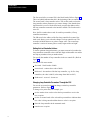
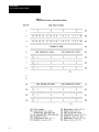
1
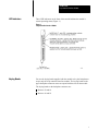
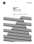
Product Data Loop Controller Interface Module Table 1 Interface Module Commands Function Command Command Code Change the set point, output, and operating mode. Acknowledge alarms. Set Control 4000 Monitor the set point, output, alarm status, and operating mode. Loop Status 4000 Change PID parameters, alarm limits, and output limits. Modify Parameters 0010 Examine PID parameters, alarm limits, and output limits. Read Parameters 0020 Transfer a configuration from a loop controller Upload 00040007 Transfer a configuration to a loop controller Download 000C000F Gather data from inputs and outputs Extended Loop Status 0080 Examine error codes Error Record 00F0 Important: The loop controller must be in the workstation mode before the interface module can change the loop controller’s parameters. 1771LI/1771LC Compatibility The chart that follows shows you what features you can use with the 1771-LI/1771-LC modules you have. 1771LC, Series A 1771LC, Series B 1771LI, Rev A Set Control Loop Status Set Control Loop Status 1771LI, Rev B Set Control Loop Status Set Control Read/Modify Parameters Loop Status Ext. Loop Status Upload Download For more detailed loop controller information, refer to the Loop Controller User’s Manual, publication 1771-6.5.42. 2 Product Data Loop Controller Interface Module LED Indicators Three LED indicators on the front of the module indicate the module’s current operating status.(Figure 1.) Figure 1 Loop Controller Interface Module Keying Bands You use the keying bands supplied with the module to key the backplane to accept only the loop controller interface module. The keying bands on the upper backplane connector must correspond with the slots on the module. The keying bands on the backplane connector are: Between 12 and 14 Between 16 and 18 3 Product Data Loop Controller Interface Module Installing the Module Connecting the Loop Controller to the Module To insert a module into the I/O chassis: 1. Remove power from the I/O chassis. 2. Open the module locking latch and insert the interface module into the slot keyed for it. 3. Firmly press the module into its backplane connector. 4. Secure the module in place with the module locking latch. 5. Reconnect power to the I/O chassis. The RS-485 serial link allows the module to communicate with up to 15 loop controllers. Connect the two devices with twisted-pair cable suitable for RS-485 wiring. You make these connections at the module’s swing arm terminals (cat. no. 1771-WA). The swing arm allows you to remove the module without having to remove the wiring. Use twinaxial cable (cat. no. 1770-CD) for the serial link or any shielded twisted-pair cable that has a minimum characteristic impedance of 60 ohms and has a maximum capacitance of 75 pF per meter. Connect the module and loop controllers in a daisychain configuration as long as total cable length does not exceed 4000 ft. Use the following procedure to connect the loop controller to the module: 4 1. Strip 2 inches of the outer insulation from the cable end to be connected to the wiring arm.(Figure 2.) 2. Remove the exposed foil. 3. Strip approximately 3/8 inch of insulation from the end of each wire. 4. Connect the wires to the module as shown in figure 3. 5. Repeat steps 1 through 4 for the cable end to be connected to the loop controller’s terminal block. Product Data Loop Controller Interface Module Figure 2 Cable Preparation 5 Product Data Loop Controller Interface Module Figure 3 Loop Controller/Interface Module Wiring Electrostatic Damage 6 To prevent static damage, we construct, test, and pack our products in a static free environment. We ship our products that require individual protection in bags that are sealed and shielded from static. When removing a product from a bag or disassembling a device, do so in a static safe environment. Product Data Loop Controller Interface Module CAUTION: If you handle components improperly, the electrostatic discharge can damage them. Handle equipment and components only in a static safe environment. PLC Data Table Requirements You must allocate two blocks of memory within the PLC’s data table for use by the interface module. The module requires this memory for block transfer read and write files. The maximum length of the block transfer write file is 64 words. Set the length of the write file to the default value of 00. The maximum length of the block transfer read file is 64 words. Set the length of the read file to 00 which allows the module to determine the proper file length. You will also need to allocate portions of the data table for the files related to the module’s commands. Set Control Command This command enables the PLC to: specify the number of loop controllers attached to the communication link select either the auto mode or the manual mode specify either a remote or local set point enter the value of a new set point or output acknowledge alarms The PLC sends the command to the module via block transfer instructions. The module interprets the command and sends the appropriate message out to the loop controllers over the RS-485 serial link. Important: The loop controller must be in the manual mode to change an output. The loop controller can be in either the automatic or manual mode when changing a set point. Set control setpoint/output values are four-digit BCD numbers which represent percent of scale. These values can range between -2.0 and + 102.0. Negative values have their most significant bit set. 7 Product Data Loop Controller Interface Module The first word of the set control file is the block header. Refer to figure 4. This word (4000) indicates that this is the beginning of the set control file. The second word is loop controller select. You use this word to select the loop controller whose parameters you want to change. Note that the least significant bit is reserved. In the third word you place the address of the last loop controller connected to the interface module. The fourth word is reserved. Next, the file contains three words for each loop controller (15 loop controllers maximum). The fifth word is the address of the first loop controller. Set control, the sixth word, allows you to select the changes for loop controller one. The seventh word holds the new set point or output value. The second loop controller’s section of memory (three words) begins with word eight. Setting the Last Controller Address To ensure optimum loop performance, you must consecutively number the loop controllers connected to the serial link. Begin with number one and do not skip any numbers when you number them. You specify the number of loop controllers in the set control file. (Refer to figure 4.) Initially, the file must contain: first word – block header of 4000 second word – station select value of 0000 third word – the number of the last loop controller, e.g. for five loop controllers, the value is 0005 (values range from 0001 to 0015) fourth word – reserved – do not use Changing Loop Controller Parameters Through the PLC You use the set control command to change certain loop controller parameters. (Refer to figure 4.) To change a set point value, for example, you: use the station select word to select the loop controller to receive the new set point use the set control word of the selected loop controller to indicate that a new value is being entered and that the new value is a set point place the loop controller in the automatic mode enter the new set point 8 Product Data Loop Controller Interface Module Acknowledging Alarms from the PLC If a configured alarm condition develops, the alarm indicator on the front of the loop controller flashes. Also, the corresponding alarm bits are set to 1 in the alarm status word (loop status file). The indicator continues to flash until you acknowledge the alarm. You acknowledge the alarm either by pressing the ACK key on the loop controller or through the PLC. Once you acknowledge the alarm the indicator stops flashing but remains lit until you correct the problem. Refer to the Loop Controller User’s Manual, publication 1771-6.5.42, for additional information. To acknowledge an alarm from the PLC, set bit 7 (alarm acknowledge) of the set control word for that loop controller. Monitoring the Loop Controller's Configuration Whenever you advance past the loop controller’s configuration passcode, the front panel change indicator (bit 0) of the loop controller alarm/ status word is set. You acknowledge the advance past the configuration passcode by setting the user interface acknowledge bit of the set control command (bit 2). This resets bit 0 of the loop status word. 9 Product Data Loop Controller Interface Module Figure 4 Set Control Format - (Block Transfer Write) 10 Product Data Loop Controller Interface Module Set Control Word Bit Definitions Loop Status Bit Definition 0 1 2 3 4 5 6 7 New value specified A/M select (0 = manual, 1 = auto) User interface acknowledge R/L setpoint select (0 = local, 1 = remote) Reserved New value select (0 = output, 1 = setpoint) Reserved Alarm acknowledge Loop status is the module’s response to a set control command from the PLC. Loop status is also the module’s default response when no set control command is issued. The data in this file represents each loop controller’s current set point, measurement, output, alarms, and status. Loop Status File The first four words of the loop status file contain loop controller selection and diagnostic information that applies to all loop controllers connected to the interface module. (Figure 5.) The first word, the block header, indicates that this is the beginning of the loop status file. The second word, loop controller select acknowledge, shows which loop controllers responded to the most recent set control command. The third word, the no response word, indicates which loop controllers did not respond when polled. Note that bit 0 of words two and three is reserved. The fourth word, the diagnostic word, shows which loop controller has an improper value in the last set control command. Each loop controller has a four-word reserved area of memory in the loop status file. The first word in each loop controller’s area is the alarm/status word which indicates the loop controller’s current status. The three remaining words contain three values that reflect the loop’s current operating values: set point, measurement, and output. These values are fourdigit BCD numbers which represent percent of scale. The values can range from -2.0 to + 102.0. Negative values have their most significant bit set. The module continuously polls each loop controller for its current status. When a loop controller responds, the interface module places the updated status values in the loop controller’s area. When a loop controller does not respond to a module’s status request, its area contains all zeroes. If a loop controller does not respond to a status request after three tries, the interface module sets a bit in the no response word. 11 Product Data Loop Controller Interface Module Figure 5 Loop Status File Format - (Block Transfer Read) 12 Product Data Loop Controller Interface Module Loop Controller Alarm/Status Word Bit Definition 0 2 1 3 4 5 6 7 10 11 12 13 14 15 16 17 Front Panel Change Indicator A/M Setting (0 = manual, 1 = auto) W/P Setting (0 = panel, 1 = workstation) R/L Setpoint select (0 = local, 1 = remote) Undefined Undefined Undefined Alarm Indicator (1 = at least one alarm is active) Alarm 4 H/L ( 0 = lowlevel 2, 1 = highlevel 1) Alarm 4 Valid (1 = alarm is active) Alarm 3 H/L Alarm 3 Valid Alarm 2 H/L Alarm 2 Valid Alarm 1 H/L Alarm 1 Valid Diagnostic Word Bits Definition 0-7 Controller Address (2digit BCD) 10-17 Error Code (2digit BCD) 01 = Improper BCD Value 02 = New Value Is Out Of Range 08 = Last Loop Controller Address in the Set Control File Does Not Match the Address in Loop Status 13 Product Data Loop Controller Interface Module Modify Parameters The PLC uses the modify parameters command to change the loop controller’s: PID parameters alarm limits output limits Once you use the read parameters command to examine the current loop controller parameters, you can use the modify parameters command to change these parameters. Important: Changes you make when the loop controller is in the automatic mode affect the controller’s operation as soon as it receives the command from the interface module. Figure 6 shows the command’s format. All values are in BCD. The error file reflects any detected BCD errors. The module verifies that each BCD value is valid and falls within a specified range. The file’s first word is the block header which indicates the beginning of the modify parameters file. The second word, loop controller address, identifies the loop controller whose PID parameters you want to alter. Words three through five contain the PID parameters while words six through 13 contain alarm limits. Words 14 and 15 hold the upper and lower output limit values. When the loop controller receives the command from the PLC it sends a modify parameter acknowledge value back to the PLC. Refer to figure 7. If an error occurs, the error file displays the appropriate error code. 14 Product Data Loop Controller Interface Module Figure 6 Modify Parameter File Format - (Block Transfer Write) 15 Product Data Loop Controller Interface Module Figure 7 Modify Parameter Command - (Block Transfer Read) Word # 1 0 0 1 2 0 0 LOOP CONTROLLER ADDRESS 0 (A) (B) (A) Block Header (B) Loop Controller Address Read Parameters The read parameter command enables the PLC to read the loop controller’s current: PID parameters alarm limits output limits After you examine the loop controller parameters and limits, you can change them by using the modify parameters command. Figure 8 shows the command’s format. The first word is the block header which indicates the beginning of the read parameters file. The second word, loop controller address, identifies the loop controller whose parameters you want to read. When the loop controller acknowledges this command, it sends a reply to the PLC. Refer to figure 9. The format is the same as the modify parameters format. Figure 8 Read Parameter Request - (Block Transfer Write) Word # 1 0 0 2 2 0 0 LOOP CONTROLLER ADDRESS (A) Block Header (B) Loop Controller Address 16 0 (A) (B) Product Data Loop Controller Interface Module Figure 9 Read Parameter Response File Format - (Block Transfer Read) Word # 1 0 0 2 2 0 0 LOOP CONTROLLER ADDRESS (B) 3 0 5 0 0 (C) 4 0 0 1 0 (D) 5 0 0 0 0 (E) 6 0 4 0 0 (F) 7 0 6 0 0 (G) 8 0 4 0 0 (H) 9 0 6 0 0 (I) 10 0 4 0 0 (J) 11 0 6 0 0 (K) 12 0 4 0 0 (L) 13 0 6 0 0 (M) 14 0 9 8 0 (N) 15 0 1 5 0 (O) 0 (A) (A) Block Header (B) Loop Controller Address (0115) (C) Proportional Band (1 to 8000%) (D) Integral Time (0.1 to 200.0 Minutes) (E) Derivative Time (0.1 to 100.0 Minutes) (F) Alarm 1 - Level 1 (99.9 to 102.0%) (G) Alarm 1 - Level 2 (99.9 to 102.0%) (H) Alarm 2 - Level 1 (99.9 to 102.0%) (I) Alarm 2 - Level 2 (99.9 to 102.0%) (J) Alarm 3 - Level 1 (99.9 to 102.0%) (K) Alarm 3 - Level 2 (99.9 to 102.0%) (L) Alarm 4 - Level 1 (99.9 to 102.0%) (M) Alarm 4 - Level 2 (99.9 to 102.0%) (N) Output - Upper Limit (2.0 to 102.0) (O) Output - Lower Limit (2.0 to 102.0) (P) Implied Decimal Point Upload The upload command allows you to store a loop controller’s configuration in the PLC’s data table. Note that the configuration data is not in readable form. You use the download command to transfer this stored configuration back to a loop controller at a later time. The upload command permits the PLC to read the loop controller’s memory using four block transfer read operations. Each block transfer moves a specific section of loop controller memory (64 words each). Figure 10 shows the format of the upload command(s).Notice that the only difference between the commands is the command code. 17 Product Data Loop Controller Interface Module When the loop controller acknowledges the PLC’s request, it begins sending data. Refer to figure 11. The interface module calculates a checksum value as each block of data transfers from the loop controller to the PLC. This checksum is used to verify that no data sent to the PLC was altered. Caution: Do not alter the data that you transferred to the PLC. If you alter the data and download it to the loop controller without proper testing, unexpected process control could result. Figure 10 Upload Command Format - (Block Transfer Write) Word # 1 0 0 0 2 0 0 LOOP CONTROLLER ADDRESS 4 (A) (B) (A) Block Header - 0004, 0005, 0006, and 0007 (B) Loop Controller Address Figure 11 Upload File Format - (Block Transfer Read) Word # 1 0 0 2 2 0 0 LOOP CONTROLLER ADDRESS (B) 3 0 5 0 (C) 0 0 (A) 63 64 (A) Block Header - 0004, 0005, 0006, and 0007 (B) Loop Controller Address (C) Beginning of Configuration Data (D) End of Configuration Data (E) Checksum Download 18 The download command enables the PLC to send back to a loop controller the contents of memory previously uploaded to the data table. The download command is actually four commands as shown in figure 12. The PLC uses the four block transfer write operations to transfer the memory contents back to the loop controller. The loop controller should be in the manual mode when you transfer data from the PLC. Product Data Loop Controller Interface Module The interface module calculates a checksum as the data transfers back to the loop controller. The module then compares the download checksum to the internally calculated checksum to verify that no data was altered. When the loop controller accepts the data transferred from the PLC, it sends an acknowledgement as shown in figure 13. Figure 12 Download File Format - (Block Transfer Write) Word # 1 0 0 0 2 0 0 LOOP CONTROLLER ADDRESS C (A) (B) (C) 3 63 64 (A) Block Header - 000C, 000D, 000E, and 000F (B) Loop Controller Address (C) Beginning of Configuration Data (D) End of Configuration Data (E) Checksum Figure 13 Download Acknowledge - (Block Transfer Read) Word # 1 0 0 0 2 0 0 LOOP CONTROLLER ADDRESS C (A) (B) (A) Block Header - 000D, 000E, 000F, and 000G (B) Loop Controller Address 19 Product Data Loop Controller Interface Module Extended Loop Status The PLC uses the extended loop status command to gather data from: 4 analog inputs 2 frequency inputs 2 Contact inputs 2 analog outputs 2 contact outputs This command can return data from only five consecutive loop controllers at a time. (Figure 14.) If you select more than five loop controllers, the interface module processes the controllers with the five lowest addresses. All values in extended loop status file are in BCD and are expressed in percent of scale. The values can range from -2.0 to 102.0. (Figure 15.) Figure 14 Extended Loop Status Command Format Word # 1 0 0 8 0 (A) 2 15 14 13 12 11 10 09 08 07 06 05 04 03 02 01 RS (B) (A) Block Header (B) Loop Controller Select (RS=reserved) 20 Product Data Loop Controller Interface Module Figure 15 Extended Loop Status File Format 0 0 8 0 (A) 15 14 13 12 11 10 09 08 07 06 05 04 03 02 01 RS (B) 0 0 LOOP CONTROLLER ADDRESS (C) 1 0 2 0 (D) 1 0 2 0 (E) 1 0 2 0 (F) 1 0 2 0 (G) 1 0 2 0 (H) 1 0 2 0 (I) 0 CI 1 & 2 0 C0 1 & 2 (J) 1 0 2 0 (K) 1 0 2 0 (L) 0 0 LOOP CONTROLLER ADDRESS (N) 1 0 2 0 (D) 1 0 2 0 (E) 1 0 2 0 (F) 1 0 2 0 (G) 1 0 2 0 (H) 1 0 2 0 (I) 0 CI 1 & 2 0 C0 1 & 2 (J) 1 0 2 0 (K) 1 0 2 0 (L) (A) Block Header (B) Loop Controller Acknowledge (RS = reserved) (C) First Loop Controller Requested (D) Input A (E) Input B (F) Input C (G) Input D (H) Input E (I) Input F (J) Contact In/Out (K) Output 1 (L) Output 2 (M) Implied Decimal Point (N) Last Loop Controller Requested Contact Inputs (CI 1 & 2) Bit 0 = Input 1 (0 = Open, 1 = Closed) Bit 1 = Input 2 (0 = Open, 1 = Closed) Contact Outputs (CO 1 & 2) Bit 0 = Output 1 (0 = Open, 1 = Closed) Bit 1 = Output 2 (0 = Open, 1 = Closed) 21 Product Data Loop Controller Interface Module Error File When the interface module cannot process a command other than a set control or an extended status command, an error file contains an error code identifying the problem. (Figure 16.) Figure 16 Error Record Format Word # 1 0 2 COMMAND CODE 3 0 0 8 0 ERROR CODE 0 LOOP CONTROLLER ADDRESS Error Code 01 Invalid loop controller address specified in the command 02 Address of the responding loop controller does not match the address requested by the interface module 03 Loop controller did not respond with a valid return code within three tries 04 Improper checksum was detected during a download operation 05 Improper BCD character in a data field 06 A modify parameters value is out of range 07 Module cannot execute a modify parameters, a download, or a set control command when the loop controller is in the panel mode. Loop controller must be in the workstation mode. 08 Modify parameters command requires additional data. This command expects 15 words of data. If some of the data is missing, an error is indicated. Command Code 22 10 Modify parameters 20 Read parameters 0407 Upload blocks 1 through 4 0C0F Download blocks 1 through 4 Product Data Loop Controller Interface Module Specifications Module Location G 1771I/O Chassis Maximum Number of Loop Controllers G 15 Operating Temperature Loop Status Update Time G 0 to 60° C G 32 to 140° F G Approximately 2 sec/15 loops Storage Temperature G 40 to 85° C G 40 to 185° F G 4800 baud G Half duplex Relative Humidity Rating G 5 to 95% (without condensation) G 5VDC G 1.3A Electrical Interface G RS485 multidrop up to 4000 ft Keying G Between 12 and 14 G Between 16 and 18 Communication Rate Backplane Power Requirement 1987 Allen-Bradley Company, Inc. PLC is a registered trademark of Allen-Bradley Company, Inc. 23 Product Data Loop Controller Interface Module With offices in major cities worldwide WORLD HEADQUARTERS Allen-Bradley 1201 South Second Street Milwaukee, WI 53204 USA Tel: (1) 414 382-2000 Telex: 43 11 016 FAX: (1) 414 382-4444 EUROPE/MIDDLE EAST/AFRICA HEADQUARTERS Allen-Bradley Europe B.V. Amsterdamseweg 15 1422 AC Uithoorn The Netherlands Tel: (31) 2975/43500 Telex: (844) 18042 FAX: (31) 2975/60222 Publication 1771-2.109 – October 1987 Supersedes Publication 1771-2.109 – February/May 1987 24 As a subsidiary of Rockwell International, one of the world’s largest technology companies — Allen-Bradley meets today’s challenges of industrial automation with over 85 years of practical plant-floor experience. More than 11,000 employees throughout the world design, manufacture and apply a wide range of control and automation products and supporting services to help our customers continuously improve quality, productivity and time to market. These products and services not only control individual machines but integrate the manufacturing process, while providing access to vital plant floor data that can be used to support decision-making throughout the enterprise. ASIA/PACIFIC HEADQUARTERS Allen-Bradley (Hong Kong) Limited Room 1006, Block B, Sea View Estate 28 Watson Road Hong Kong Tel: (852) 887-4788 Telex: (780) 64347 FAX: (852) 510-9436 CANADA HEADQUARTERS Allen-Bradley Canada Limited 135 Dundas Street Cambridge, Ontario N1R 5X1 Canada Tel: (1) 519 623-1810 FAX: (1) 519 623-8930 LATIN AMERICA HEADQUARTERS Allen-Bradley 1201 South Second Street Milwaukee, WI 53204 USA Tel: (1) 414 382-2000 Telex: 43 11 016 FAX: (1) 414 382-2400 PN 955102-74 Printed in USA