1
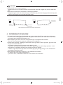
Pressure regulator
Location of brazing
Nitrogen
Taping
Nitrogen
Valve
Refrigerant pipe
Fig. 2
CAUTION
• Do not use an anti-oxidizing agent when brazing the piping.
(Residual debris could clog the piping or cause parts to malfunction.)
• For more information about outdoor unit refrigerant pipes, see the installation manual included with the
outdoor unit or the Engineering Guide.
(Failure to purge air from the pipes or fill additional refrigerant may result in an insufficient volume of
refrigerant in the pipes or other problems, causing the equipment to malfunction [for example, to not cool
or heat properly].)
6-3 Piping connection
Notes
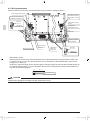
In case of connecting with a 20-50 type indoor
unit, there is no need to cut and connect as it is.
In case of others, cut the outlet pipe and
connect to the connecting pipe.
In accordance with the following instructions.
Liquid pipe (*1)
BS unit (top)
Suction gas pipe (*1)
HP/LP gas pipe (*1)
Unit D
Unit C
Unit B
Unit A
Connection area
Reducing joint (*2)
Gas pipe (*1)
Liquid pipe (*1)
Connect
Cutting point
(Center of
connection area)
Local pipe
(*1) Indicates local pipe.
(*2) Reducing joint may be required (field supply) if the local pipe size does not suit on the pipe size of the
BS unit (Table 5).
If there are branch ports left unused (not connected to an indoor unit)
• If there are unused branch ports, use stopper pipe (7) (accessory).
If there are numerous unused branch ports, be sure to use the stop pipe kit (KHFP26A100C).
Be sure to use the stop valve kit for extension (KHFP26M224, sold separately), for branch ports that
you plan to expand in the future.
6-4 Airtightness test and vacuum drying
• After completing refrigerant piping work for the indoor units, BS unit, and outdoor unit, conduct an airtightness test and vacuum drying.
For more information about the airtightness test pressure, refer to the outdoor unit’s installation manual.
10
01_EN_3P194121-8U.indd 10
English
2/21/2014 3:31:08 PM