1
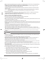
3. SELECTING INSTALLATION SITE
BS unit
Top of unit
500 or more (*1)
Indoor unit
side pipe
450 (*2)
70
Control box
100 or more
300 or
more
100 or more (*3)
Consider the following requirements when choosing the installation location and obtain the customer’s consent:
• The location must be able to withstand the weight of the BS unit.
• The location must allow reliable draining.
• The location must allow inspection holes to be installed on the control box side. (A separate opening is
necessary when lowering the product.)
• There must be adequate space in which to perform installation and service work (Refer to Fig. 1).
• The length of pipe to the indoor unit and outdoor unit must be less than or equal to the permissible pipe
length (as listed in the installation manual that came with the outdoor unit).
• The sound of refrigerant being pumped through the pipes must not be a problem. (Never install above the
ceiling of an occupied room.)
Inspection hole
450 × 450
Drain pan
Maintenance space
Control box and
motorized valve coil
Maintenance space
(*1)
Unit: mm
Fig. 1
(*1) Leave enough space to connect the site pipes.
(*2) This space is needed to place the top plate when performing service on the motor operated valve coil.
(*3) This space is needed to remove the top plate when performing service on the motor operated valve
coil.
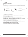
WARNING
Securely install the unit at a location that is capable of withstanding its weight.
Inadequate strength may cause the indoor unit to fall, resulting in bodily injury.
CAUTION
• Leave enough space to perform maintenance on the drain pan and control box.
• To prevent video and audio interference, install the BS unit as well as associated power wiring and signal
transmission lines at least 1 m away from TVs and radios.
However, depending on the reception, interference may result even if a minimum distance of 1 m is maintained.
English
01_EN_3P194121-8U.indd 5
5
2/21/2014 3:31:06 PM