1
Customer Notification
V850E/PH2
32-Bit Single-Chip Microcontrollers
Operating Precautions
μPD70F3187
μPD70F3447
μPD76F0053
Document No. U18082EEAV1IF00
Date Published July 2007
© NEC Electronics (Europe) GmbH
DISCLAIMER
The related documents in this customer notification may include preliminary versions. However, preliminary
versions may not have been marked as such.
The information in this customer notification is current as of its date of publication. The information is subject
to change without notice. For actual design-in, refer to the latest publications of NEC’s data sheets or data
books, etc., for the most up-to-date specifications of NEC PRODUCT(S). Not all PRODUCT(S) and/or types
are available in every country. Please check with an NEC sales representative for availability and additional
information.
No part of this customer notification may be copied or reproduced in any form or by any means without prior
written consent of NEC. NEC assumes no responsibility for any errors that may appear in this customer
notification. NEC does not assume any liability for infringement of patents, copyrights or other intellectual
property rights of third parties by or arising from the use of NEC PRODUCT(S) listed in this customer
notification or any other liability arising from the use of such PRODUCT(S).
No license, express, implied or otherwise, is granted under any patents, copyrights or other intellectual
property rights of NEC or others. Descriptions of circuits, software and other related information in this
customer notification are provided for illustrative purposes of PRODUCT(S) operation and/or application
examples only. The incorporation of these circuits, software and information in the design of customer’s
equipment shall be done under the full responsibility of customer. NEC assumes no responsibility for any
losses incurred by customers or third parties arising from the use of these circuits, software and information.
While wherever feasible, NEC endeavors to enhance the quality, reliability and safe operation of
PRODUCT(S) the customer agree and acknowledge that the possibility of defects and/or erroneous thereof
cannot be eliminated entirely. To minimize risks of damage to property or injury (including death) to persons
arising from defects and/or errors in PRODUCT(S) the customer must incorporate sufficient safety measures
in their design, such as redundancy, fire-containment and anti-failure features.
The customer agrees to indemnify NEC against and hold NEC harmless from any and all consequences of
any and all claims, suits, actions or demands asserted against NEC made by a third party for damages
caused by one or more of the items listed in the enclosed table of content of this customer notification for
PRODUCT(S) supplied after the date of publication.
Applicable Law:
The law of the Federal Republic of Germany applies to all information provided by NEC to the Customer under
this Operating Precaution document without the possibility of recourse to the Conflicts Law or the law of 5th
July 1989 relating to the UN Convention on Contracts for the International Sale of Goods (the Vienna CISG
agreement).
Düsseldorf is the court of jurisdiction for all legal disputes arising directly or indirectly from this information.
NEC is also entitled to make a claim against the Customer at his general court of jurisdiction.
If the supplied goods/information are subject to German, European and/or North American export controls,
the Customer shall comply with the relevant export control regulations in the event that the goods are
exported and/or re-exported. If deliveries are exported without payment of duty at the request of the
Customer, the Customer accepts liability for any subsequent customs administration claims with respect to
NEC.
Notes: 1. “NEC” as used in this statement means NEC Electronics Corporation and also includes its direct
or indirect owned or controlled subsidiaries.
2. “PRODUCT(S)” means ‘NEC semiconductor products’ (NEC semiconductor products means any
semiconductor product developed or manufactured by or for NEC) and/or ‘TOOLS’ (TOOLS
means ‘hardware and/or software development tools’ for NEC semiconductor products’
developed, manufactured and supplied by ‘NEC’ and/or ‘hardware and/or software development
tools’ supplied by NEC but developed and/or manufactured by independent 3rd Party vendors
worldwide as their own product or on contract from NEC)
2
Customer Notification U18082EEAV1IF00
Operating Precautions for V850E/PH2
Table of Contents
(A)
Table of Operating Precautions . . . . . . . . . . . . . . . . . . . . . . . . . . . . . . . . . . . . 3
(B)
Description of Operating Precautions. . . . . . . . . . . . . . . . . . . . . . . . . . . . . . . 7
(C)
Valid Specification . . . . . . . . . . . . . . . . . . . . . . . . . . . . . . . . . . . . . . . . . . . . . 27
(D)
Revision History . . . . . . . . . . . . . . . . . . . . . . . . . . . . . . . . . . . . . . . . . . . . . . . 28
Customer Notification U18082EEAV1IF00
1
Operating Precautions for V850E/PH2
2
Customer Notification U18082EEAV1IF00
Operating Precautions for V850E/PH2
(A) Table of Operating Precautions
μPD70F3187
μPD76F0053
No.
Outline
Rev.
ES1.1
ES2.0
ES2.1
ES2.2
RankNote
1
iRAM: Parity check of internal RAM does not work.
(Technical limitation)
✗
✓
✓
✓
2
TMP/TMT/TMR: External event counter mode shorts first
output pulse
(Specification change notice)
✗
✗
✗
✗
TMP/TMT/TMR: External event counter mode does not work
correctly when compare register value is 0000H
(Specification change notice)
✗
✗
✗
✗
TMP/TMT/TMR: Capture operation of illegal data before first
counting up
(Specification change notice)
✗
✗
✗
✗
5
TMP/TMT/TMR: First count up timing might be shorten
(Technical limitation)
✗
✗
✓
✓
6
TMT: Compare and clear function does not work at start timing in encoder mode
(Specification change notice)
✗
✗
✗
✗
7
AFCAN: Rx limitation
(Technical limitation)
✗
✗
✓
✓
8
Flash Memory: Boot swap may work incorrect
(Specification change notice)
✗
✗
✗
✗
9
CSIB: Subsequent transfer in single transfer mode may fail
(Specification change notice)
✗
✗
✗
✗
10
DMAC: DMA transfer from/to CSIB or UARTC may fail
depending on the transfer speed of the serial interface
(Technical limitation)
✗
✗
✗
✓
11
DMAC: DMA transfer lost
(Technical limitation)
✗
✗
✗
✓
12
AFCAN: Malfunction of debug control register
(Technical limitation)
✓
✗
✗
✓
13
Firmware: Selfprogramming library returns error message
on successful security setup
(Technical limitation)
✗
✗
✗
✓
Firmware: Writing security flags via self programming library
may fail
(Technical limitation)
✗
✗
✗
✓
3
4
14
Customer Notification U18082EEAV1IF00
3
Operating Precautions for V850E/PH2
μPD70F3187
μPD76F0053
No.
Outline
Rev.
ES1.1
ES2.0
ES2.1
ES2.2
Firmware: Programming tool receives status messages in
reverse order on verify operation in case of frame errors
(Technical limitation)
✗
✗
✗
✓
Firmware: Polling mode emulation by selfprogramming
library fails
(Technical limitation)
✓
✗
✗
✓
17
AFCAN: Sleep Mode Wakeup
(Specification change notice)
✗
✗
✗
✗
18
CSIB: Slave mode stop condition
(Specification change notice)
✗
✗
✗
✗
19
TMT: Encoder load enable mode limitation
(Specification change notice)
✗
✗
✗
✗
RankNote
15
16
✓ : Not applicable
✗ : Applicable
Note: The rank is indicated by the letter appearing at the 5th position from the left in the lot number, marked
on each product.
4
Customer Notification U18082EEAV1IF00
Operating Precautions for V850E/PH2
μPD70F3447
No.
Rev.
Outline
ES1.0
ES1.1
RankNote
1
iRAM: Parity check of internal RAM does not work.
(Technical limitation)
✓
✓
2
TMP/TMT/TMR: External event counter mode shorts first
output pulse
(Specification change notice)
✗
✗
TMP/TMT/TMR: External event counter mode does not work
correctly when compare register value is 0000H
(Specification change notice)
✗
✗
TMP/TMT/TMR: Capture operation of illegal data before first
counting up
(Specification change notice)
✗
✗
5
TMP/TMT/TMR: First count up timing might be shorten
(Technical limitation)
✓
✓
6
TMT: Compare and clear function does not work at start timing in encoder mode
(Specification change notice)
✗
✗
7
AFCAN: Rx limitation
(Technical limitation)
✓
✓
8
Flash Memory: Boot swap may work incorrect
(Specification change notice)
✗
✗
9
CSIB: Subsequent transfer in single transfer mode may fail
(Specification change notice)
✗
✗
10
DMAC: DMA transfer from/to CSIB or UARTC may fail
depending on the transfer speed of the serial interface
(Technical limitation)
✗
✓
11
DMAC: DMA transfer lost
(Technical limitation)
✗
✓
12
AFCAN: Malfunction of debug control register
(Technical limitation)
✗
✓
13
Firmware: Selfprogramming library returns error message
on successful security setup
(Technical limitation)
✗
✓
Firmware: Writing security flags via self programming library
may fail
(Technical limitation)
✗
✓
3
4
14
Customer Notification U18082EEAV1IF00
5
Operating Precautions for V850E/PH2
μPD70F3447
ES1.0
ES1.1
Firmware: Programming tool receives status messages in
reverse order on verify operation in case of frame errors
(Technical limitation)
✗
✓
Firmware: Polling mode emulation by selfprogramming
library fails
(Technical limitation)
✗
✓
17
AFCAN: Sleep Mode Wakeup
(Specification change notice)
✗
✗
18
CSIB slave mode stop condition
(Specification change notice)
✗
✗
19
TMT ’Encoder load enable’-mode limitation
(Specification change notice)
✗
✗
No.
Rev.
Outline
RankNote
15
16
✓ : Not applicable
✗ : Applicable
Note: The rank is indicated by the letter appearing at the 5th position from the left in the lot number, marked
on each product.
6
Customer Notification U18082EEAV1IF00
Operating Precautions for V850E/PH2
(B) Description of Operating Precautions
No. 1
iRAM: Parity check of internal RAM does not work.
(Technical limitation)
Details
The parity check feature of the internal RAM is not implemented. Therefore the dedicated interrupt request (INTPERR) has no effect, and the corresponding interrupt control register (PIC105)
has no meaning. Moreover, the contents of the RAM parity error flag register (RAMERR) as well
as the RAM parity error address register (RAMPADD) are undefined.
Workaround
None.
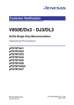
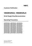
No. 2
TMP/TMT/TMR: Event counter mode shorts first output pulse
(Specification change notice)
Details
If timer P (TMP), timer T (TMT) or timer R (TMR) uses a timer output in event-mode, the pulse
width of timer output is different in the first period.
Example
TxnCE
TEVTnx
Sampling
Clock
TnxCNT
FFFFH
0000H
0001H
0002H
0000H
0001H
0002H
0002H
TnxCCR0
INTTnxCC0
TOxn0
width of 2 counts
width of 3 counts
Remarks: 1. x = P, R or T
2. n = 0 to 7,
= 0 or 1,
if x = P
if x = R or T
Workaround
Do not use timer outputs in external event count mode. Instead of this use the interval mode with
enabled external clock input (TEVTxn) by setting the TxnEEE bit of the TxnCTL1 register to 1.
Customer Notification U18082EEAV1IF00
7
Operating Precautions for V850E/PH2
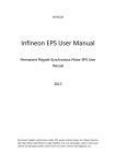
No. 3
TMP/TMT/TMR: External event counter mode does not work correctly when compare register
value is 0000H
(Specification change notice)
Details
In the external event count mode (TxnMD3 to TxnMD0 bits = 0001B) the counter (TxnCNT) is not
compared with the compare register value (TxnCCR0) during first count up timing. Therefore,
when TxnCCR0 is set to 0000H, the counter cannot be cleared and the compare match interrupt
signal (INTTxnCC0) is not output. In this case the timer counts up until FFFFH in the first period,
and not until then the compare match works as excepted.
Example
TxnMD3 to TxnMD0 bits = 0001B (External event count mode), TxnCCR0 = 0000H
TxnCE
TEVTxn
Sampling
Clock
TxnCNT
TxnCCR0
FFFFH
0000H
0001H
FFFFH
0000H
0000H
INTTxnCC0
TOxn0
Counter is not cleared and TxnCC0 interrupt is not output
Remarks: 1. x = P, R or T
2. n = 0 to 7,
= 0 or 1,
if x = P
if x = R or T
Workaround
Do not set TxnCCR0 = 0000H in external event counter mode.
8
Customer Notification U18082EEAV1IF00
0000H
0000H
Operating Precautions for V850E/PH2
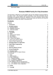
No. 4
TMP/TMT/TMR: Capture operation of illegal data before first counting up
(Specification change notice)
Details
In free-running mode (TxnMD3 to TxnMD0 bits = 0101B), pulse width measurement mode
(TxnMD3 to TxnMD0 bits = 0110B), and offset trigger generation mode (TxnMD3 to TxnMD0 bits
= 1100B, TMT only), when a lower count clock (TxnEEE = 0, TxnCKS2 to TxnCKS0 = 011B to
111B) or an external clock (TxnEEE = 1) is selected, the timer captures the value of FFFFH and
outputs a capture interrupt signal (INTTxnCCm), if a capture trigger signal (TIxnm) is enabled and
input before first counting up. This captured data and the corresponding interrupt might be useless.
Example
TxnCE
TEVTxn
Sampling
Clock
FFFFH
TxnCNT
0000H
0001H
0002H
TIxnm
TxnCCRm
0000H
FFFFH
INTTxnCCm
If capture trigger is input before first count up,
timer captures the value of FFFFH
and outputs an interrupt.
Remarks: 1. x = P, R or T
2. n = 0 to 7,
= 0 or 1,
if x = P
if x = R or T
3. m = 1,
= 1 to 4,
if x = P or T
if x = R
Workaround
None.
Customer Notification U18082EEAV1IF00
9
Operating Precautions for V850E/PH2
No. 5
TMP/TMT/TMR: First count up timing might be shorten
(Specification change notice)
Details
When a lower count clock (TxnEEE = 0, TxnCKS2 to TxnCKS0 = 011B to 111B) is selected, the
timer miscounts at start timing when the count clock signal level is “H”. The width of a TOxnm
pulse output might be narrow about 1/2 period of the selected count clock at worst case.
Workaround
None.
No. 6
TMT: Compare and clear function does not work at start timing in encoder mode
(Technical limitation)
Details
In encoder compare mode (TxnMD3 to TxnMD0 bits = 1000B), or encoder capture-compare
mode (TxnMD3 to TxnMD0 bits = 1010B), if the compare registers (TTnCCR0, TTnCCR1) are set
to the same value of TTnTCW register when TTnECC bit = 0, the timer cannot perform the comparison with the compare registers (TTnCCR0, TTnCCR1) and TTnTCW register (which is the
start value of TTnCNT). In this case the “encoder clear mode on match of counter and compare
register” does not work at the start timing (TTnECM0 = 1, and/or TTnECM1 = 1).
Workaround
None
10
Customer Notification U18082EEAV1IF00
Operating Precautions for V850E/PH2
No. 7
AFCAN: Rx limitation
(Technical limitation)
Details
The aFCAN macro may store an incoming message although this message was interrupted by a
bus error frame. Thus, the incomplete reception causes that a message buffer is updated with old
or incorrect data or that the message is even stored at an incorrect location.
This unexpected behaviour affords that the bus error occurs in a certain relation to the currently
present message on the bus. The critical time window starts at the sample point of the LSB of the
DLC-field and lasts for the duration of an internal process in the aFCAN macro (RX-search). This
time window usually lasts for a few bit times only. The actual length depends on the clock supply
for the AFCAN, the CPU accesses during this period, the baud rate and the number of message
buffers of the particular AFCAN macro.
In this time window the RX-search evaluates the received identifier of the current message. When
the bus error is detected within this window and when the RX-search has just scanned buffer #n
for reception and found it is matching, the message will unexpectedly be treated as a received
message. As the time window is limited as described above, only a stuff bit error occurring right in
this window can cause this behaviour.
There are two types of unexpected behavior for the RX limitation depending on the presence of
pending transmission request (TRQ) for any other message buffer.
1. Behavior at pending TRQ (TRQi = 1)
When the host processor has already submitted a transmit request (TRQ) for at least one buffer,
the unexpected reception of the message will take place into the message buffer found by internal
RX-search. This is the correct location to store the message i.e. the acceptance filter criteria are
correctly fulfilled. However the data part will be updated with the contents of the shift register of
the CAN protocol core. As this register is immediately stopped at detection of the bus error, the
data provided to the message buffer can not be interpreted by the host processor.
TRQi=1
CAN bus
Stuff Error
Rx Frame
Error Frame
IM
RX/TX Frame
INTERR
zoomed
Internal action
INTREC
Rx Search
Scanning Msg#n
As during a regular reception, the RX-interrupt (if enabled) is generated and the application processes the message object.
Customer Notification U18082EEAV1IF00
11
Operating Precautions for V850E/PH2
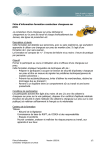
No. 7
AFCAN: Rx limitation
(Technical limitation)
(cont.)
2. Behavior without pending TRQ (TRQi = 0)
In case the host processor has not submitted a transmit request (TRQ) for any buffer before the
detection of the bus error but submits TRQ = 1 after that point in time (see figure below) before
the re-transmission of the message interrupted by the stuff bit error started, the unexpected
reception of the message will take place.
Stuff Error
CAN bus
Rx Frame
TRQi=1
Error Frame
INTERR
IM
RX/TX Frame
INTREC
zoomed
Internal action
Rx Search
Scanning Msg#n
The unexpected storage of the message is issued in the particular message buffer that matches
the acceptance filter criteria at the time where the bus error is detected (as described in 1.) or the
message buffer #0 is overwritten independently of its configuration.
Impact on application
In typical applications the RX-limitation will lead to transiently incorrect data. In the vast majority
of cases the message interrupted by a bus error is repeated by the transmitter right away. Then
the application receives correct data shortly after the unexpected reception.
In scenarios where the message buffer #0 is overwritten, the impact for the application depends
on the usage of that buffer. If it is configured as a receive buffer, the application receives a message at an unexpected location and will interpret the data to belong to the identifier originally programmed for that buffer. The message buffer #0 needs to be re-configured in order to receive the
originally intended message object again.
In case of a transmit message buffer the unexpected storage may falsify a transmit object; i.e.
when the unexpected behavior occurs after preparation of the message data but before the actual
start of transmission. This scenario is even less likely than the scenario described in 1, which
itself has a low probability. However the transmission of a falsified message can lead to repetitive
transmission attempts when the original provider of that message (identifier) tries to send its message at the same time. Then the messages most likely will differ in their data part and a bit error is
detected. This repetition resumes until one of the nodes enters error passive or bus off state.
Then the situation is resolved as all pending TRQ are send with delay or are cancelled (in case of
bus off state).
Workaround
NEC will update the affected products.
NEC does not recommend a S/W workaround as first choice as it is fairly complex. On the one
hand it is based on the control of submitting transmission requests only when the bus is idle. On
the other hand a less complex algorithm can be used which does not prevent the unexpected
reception but detects it safely and discards the unexpected reception in the CAN S/W driver. Any
of these algorithms require that message buffer #0 is not used or that a 'dummy' TRQ in an
unused buffer is set. This prevents behaviors as described in 2.
12
Customer Notification U18082EEAV1IF00
Operating Precautions for V850E/PH2
No. 8
Flash Memory: Boot swap may work incorrect
(Technical limitation)
Details
When the boot clusters are swapped, program flow into and out of the
2nd cluster (Address: 0x10000~0x20000) is not correct.
Workaround
Do use boot swap twice in the flash re-programming flow.
Between the 1st and the 2nd swap, the program flow (e.g. boot loader execution) may not exceed
the 1st boot cluster.
Customer Notification U18082EEAV1IF00
13
Operating Precautions for V850E/PH2
No. 9
CSIB: Subsequent transfer in single transfer mode may fail
(Specification change notice)
Details
In the case single transfer mode and CBnDAP=1, transmission enable interrupt (INTCBnT)
occurs at the sampling timing of the final data bit.
Next transfer operation begins by writing to CBnTX register after finishing transfer. (It is not permitted to start next transfer by writing CB0TX register during data transfer.)
When CBnTSF = 1 after transmission enable interrupt (INTCBnT) occurred, writing next data to
CBnTX register for a subsequent transfer may not start next transfer.
Therefore, if DMA is used, depending on transfer clock and access speed on the special function
registers, the transfer operation may fail.
Timing Diagrams
Transfer operation in case of single transfer mode and CBnCKP=0, CBn0DAP=1
SCKBn pin
SIBn
capture
SOBn pin
D7
D6
D5
D4
D3
D2
D1
D0
Reg-R/W
INTCBnT
interrupt
CBnTSF bit
Transfer operation in case of single transfer mode and CBnCKP=1, CBn0DAP=1
SCKBn pin
SIBn
capture
SOBn pin
D7
D6
D5
D4
D3
D2
D1
D0
Reg-R/W
INTCBnT
interrupt
CBnTSF bit
Workaround
In single transfer mode, when CBnDAP=1, check whether the CBnTSF flag is cleared (0) or not.
If CBnTSF flag = 0, write next transfer data to CBnTX register.
If DMA transfer function is used, only transfer modes with CBnDAP=0 should be used.
14
Customer Notification U18082EEAV1IF00
Operating Precautions for V850E/PH2
No. 10
DMAC: DMA transfer from/to CSIB or UARTC may fail depending on the transfer speed of the
serial interface
(Technical limitation)
Details
For both serial interfaces CSIB and UARTC, when the serial data reception is supported by DMA
transfer (channels 4 or 5), or when the serial data transmission is supported by DMA transfer
(channels 6 or 7), the DMA transfer may fail, if the base clock is below fXX/40.
The serial interface CSI3n is not concerned.
The tables below show the clock settings for which the DMA transfer operates properly for transferring data from or to the serial interfaces CSIB and UARTC, and for which clock settings it may
fail.
Clocked Serial Interface B (CSIB)
Clock selection in the CSIBn control register 1 (CBnCTL1)
After reset:
CBnCTL1
00H
R/W
Address:
CB0CTL1 FFFFFD01H,
CB1CTL1 FFFFFD21H
7
6
5
4
3
2
1
0
0
0
0
CBnCKP
CBnDAP
CBnCKS2
CBnCKS1
CBnCKS0
CBnCKS2
CBnCKS1
CBnCKS0
Base Clock (fXCCLK)
Mode
(n = 0, 1)
0
0
0
0
0
1
0
fBRG0
DMA Transfer
Okay,
if fBRG0 ≥ fXX/40
Master mode
May fail,
if fBRG0 < fXX/40
Okay,
if fBRG1 ≥ fXX/40
fBRG1
Master mode
0
fXX/8
Master mode
Okay
1
May fail,
if fBRG1 < fXX/40
0
1
1
fXX/16
Master mode
Okay
1
0
0
fXX/32
Master mode
Okay
1
0
1
fXX/64
Master mode
May fail
1
1
0
fXX/128
Master mode
May fail
Okay, if external clock
≥ fXX/40
1
1
1
External clock (SCKBn)
Slave mode
May fail, if external
clock < fXX/40
Customer Notification U18082EEAV1IF00
15
Operating Precautions for V850E/PH2
No. 10
DMAC: DMA transfer from/to CSIB or UARTC may fail depending on the transfer speed of the
serial interface
(Technical limitation)
(cont.)
Asynchronous Serial Interface C (UARTC)
Clock selection in the UARTCn control register 1 (UCnCTL1)
After reset:
UCnCTL1
00H
R/W
Address:
UC0CTL1 FFFFFA01H,
UC1CTL1 FFFFFA21H
7
6
5
4
3
2
1
0
0
0
0
0
UCnCKS3
UCnCKS2
UCnCKS1
UCnCKS0
UCnCKS3
UCnCKS2
UCnCKS1
UCnCKS0
0
0
0
0
fXX/2
Okay
0
0
0
1
fXX/4
Okay
0
0
1
0
fXX/8
Okay
Okay
(n = 0, 1)
Base clock (fXCLK) selection
DMA Transfer
0
0
1
1
fXX/16
0
1
0
0
fXX/32
Okay
0
1
0
1
fXX/64
May fail
0
1
1
0
fXX/128
May fail
0
1
1
1
fXX/256
May fail
May fail
1
-
0
0
fXX/512
1
-
0
1
fXX/1024
May fail
1
-
1
0
fXX/2048
May fail
1
-
1
1
fXX/8192
May fail
Workaround
None. Do not use DMA transfer, if the base clock of the CSIB or the UARTC is below fXX/40 = 1.6
MHz @ fXX = 64MHz.
16
Customer Notification U18082EEAV1IF00
Operating Precautions for V850E/PH2
No. 11
DMAC: DMA transfer lost
(Technical limitation)
Detail
A DMA transfers on any of channel 0,1,2,3 can be sporadically omitted under the following prerequisites:
• More than one DMA channel is operated in parallel.
• DMA transfer count register (DTCRn) on the vulnerable channel (n = 0 to 3) has reached
the count value “1”.
• The DMA trigger signal coincidences with an internal “DMA transfer end” signal on any
other active DMA channel (0 to 7) within exactly the same CPU clock cycle.
(For V850E/PH2 @ 64 MHz this corresponds to a time window of 15.6 ns).
If all of above-mentioned conditions are met, the byte or word will not be transferred and the DMA
transfer count register (DTCR) will not be decremented although the triggering on-chip peripheral
macro has requested a DMA transfer.
Workaround
Operate only one DMA channel at a time.
Stop the DMA transfer before DTCRn = 1 is reached (n = 0 to 3).
Design application SW tolerant against sporadically lost DMA transfers.
Customer Notification U18082EEAV1IF00
17
Operating Precautions for V850E/PH2
No. 12
AFCAN: Malfunction of debug control register
(Technical limitation)
Detail
An internal (hidden) debug control register at address FFFFF9F0H used for debug purpose can
be modified accidentally. In normal operation mode the content of this register is left to 01H.
If bit 7 (MSB), so-called SVCAN bit, of this register is set, the AFCAN controller will be set to
debug mode. In this mode certain pointer values and status flags of the AFCAN module are frozen and will not be automatically updated on CPU read access. This affects the CAN transmit and
reception history list and the enforced shutdown mechanism.
The malfunction arises, if bit 7 (MSB) of any even address register of the following
peripherals is set to 1:
• UART0, UART1
• CSI30, CSI31
• CSIB0, CSIB1
• BRG0, BRG1 (BRG of CSI30 and CSI31)
• BRG2 (AFO)
In this case bit 7 (SVCAN) of the hidden control register is set simultaneously to 1 and the AFCAN
debug mode is entered as described above. As a consequence a procedure that depends on the
read status of the transmit or receive history list may be blocked for further transfers.
Remark:
Due to the read-modify-write mechanism of bit manipulation instructions (e.g. SET1,
CLR1) access to any bit of aforementioned even address registers may result in
SVCAN=1 if the modified register’s MSB = 1.
1) Function of the SVCAN bit
Register
Function
SVCAN=0
CnRGPT
CPU reads CnRGPT to
get the RHL-element
indexed by RGPT
RGPT value is automatically incremented by 1 per
CnRGPT read.
RGPT value is fixed
CnTGPT
CPU reads CnTGPT to
get the THL-element
indexed by TGPT
TGPT value is automatically incremented by 1 per
CnTGPT read.
TGPT value is fixed
Enforced shutdown
While EFSD=1, reading
CGMCTRL automatically
clears the EFSD bit to disable the enforced shutdown mechanism
While EFSD=1, reading CGMCTRL does not clear the EFSD bit.
CGMCTRL
SVCAN=1
2) Clearing the SVCAN bit
The SVCAN bit can be cleared explicitly by writing 01H to the debug control register located at
address FFFFF9F0H.
However any write access to addresses located in the peripheral I/O area may also result in clearance of the SVCAN bit.
Workaround
When writing to any even address register of the peripherals above, ensure that the application
software resets the value of the hidden control register at address FFFFF9F0H to 01H by an 8-bit
write access afterwards.
18
Customer Notification U18082EEAV1IF00
Operating Precautions for V850E/PH2
No. 13
Firmware: Selfprogramming Library returns error message on successful security setup
(Technical limitation)
Detail
On evocation of the selfprogramming library’s SelfLib_SetSecFlags() command a communication error (SELFLIB_ERR_FLASHPROCn, n = 0x0 to 0x2) may be returned even though the
programming operation itself was successful.
The malfunction is caused by an internal status variable that is not updated after the first attempt
to write the security flags failed but a later retry operation succeeded.
Please note that the function updating this variable may also be used by programming tools (e.g.
PG-FP4) for setting the security flags or doing chip erase, resulting in an error message even
though the intended operation completed successfully.
Workaround
Do not use the selfprogramming library’s SelfLib_SetSecFlags() command.
No. 14
Firmware: Writing security flags via self programming library may fail
(Technical limitation)
Detail
On evocation of the selfprogramming library’s SelfLib_SetSecFlags() command a programming
error (SELFLIB_ERR_FLASHPROCn, n=0x0~0x2) may be returned if user interrupt processing
was enabled during the self programming operation.
The malfunction is caused by a user interrupt routine suspending a firmware operation at a certain vulnerable time window of firmware processing. As a consequence a write disturbance may
occur which is detected automatically by an internal verify resulting and signalled by the
(SELFLIB_ERR_FLASHPROCn, n=0x0~0x2) return value.
Workaround
Do not use interrupts during self programming.
Customer Notification U18082EEAV1IF00
19
Operating Precautions for V850E/PH2
No. 15
Firmware: Programming tool receives status messages in reverse order on verify operation in
case of frame errors
(Technical limitation)
Detail
Programming tools use a dedicated programming interface of the firmware. On verify operations
the firmware programming interface returns certain status values to the programming tool.
In case of a frame error during communication between the programming tool and the device, the
firmware returns:
Status1 = BUSY
Status2 = NACK
The expected behaviour would be to return the status information in reverse order:
Status1 = NACK
Status2 = BUSY
The PG-FP4 programming tool will recognize a “communication error” in both cases and hence is
not affected by this limitation.
The behaviour of other 3rd party programming tools needs to be carefully checked.
Workaround
Use PG-FP4 for device programming.
Check 3rd party programming tools’ behaviour on above mentioned condition.
20
Customer Notification U18082EEAV1IF00
Operating Precautions for V850E/PH2
No. 16
Firmware: Polling mode emulation by selfprogramming library fails
(Technical limitation)
Detail
The polling mode emulation of the self programming library is using the ROM correction feature of
the device. The ROM correction is configured by the selfprogramming library in such a way that
the wait routine for completion of the command in the firmware is left by the debug trap and gives
back the control to the library, respectively the application.
The original selfprogramming library was built and tested for the device version ES1.0/1.1. As the
firmware has been modified for enhancement the start address of the firmware routine has
changed.
Effect
The polling mode emulation of the selfprogramming library will not work on the concerned device
versions and the library functions will not return to user software until the initiated flash operation
has completed.
As a result the latency e.g. for triggering a H/W watchdog during selfprogramming is increased.
This limitation has no further side-effects, e.g. the ROM correction will not be activated unintendedly during execution of the selfprogramming library.
Workaround
Set the H/W watchdog period to a longer interval than the time required for the executed flash
operations.
Customer Notification U18082EEAV1IF00
21
Operating Precautions for V850E/PH2
No. 17
AFCAN: Sleep Mode Wakeup
(Specification change notice)
1. Description
When the AFCAN macro is set into SLEEP mode, it can be waken up by CAN bus activity.
This waking up is asynchronous to the operation of the macro and the CPU. By configuration setting, a WAKEUP interrupt can be generated by the AFCAN macro on the wakeup event.
While the interrupt is generated asynchronously, the AFCAN macro may need another dominant
edge on the CAN bus, or software clearing of the SLEEP mode, in order to restart its synchronous
operation.
During the time, after the interrupt already has been indicated, and before the CAN macro has
restarted its synchronous operation, the registers of the AFCAN macro will not operate, because
the AFCAN macro still remains in SLEEP mode. This time we will refer to as “wakeup dead time”
in the following context.
To resolve from the wakeup dead time, software and/or hardware measures are required.
2. Exclusions
This Operating Precaution is only applicable to applications, which are fulfilling at least one of
the following three conditions:
• SLEEP Mode of AFCAN is used and the possibility to wake up AFCAN by CAN-Bus
events is given (see remark 1 below).
• During SLEEP mode of the AFCAN macro, a CAN-Bus wakeup condition occurs, while
the AFCAN macro is supplied with clock (see remark 2 below) and
- after waking up from SLEEP mode of the AFCAN macro, the application software does
not wait until the SLEEP mode is released by polling the CnCTRL (PSMODE) register,
before continuing operation with the AFCAN macro (see remark 3 below) and
- the CPU can reach instructions, where AFCAN registers are accessed while the
AFCAN macro is still in SLEEP mode, due to the missing waiting condition.
• During SLEEP mode of the AFCAN macro, a CAN-Bus wakeup condition occurs, while
the AFCAN macro is supplied with clock (see remark 2 below) and
- after waking up from SLEEP mode of the AFCAN macro, the CAN Bus Transceiver
generates a long-lasting or permanent dominant level to the CRXD input of the
AFCAN macro, instead of the propagated CAN-Bus level.
Remarks: 1. If the CAN-Bus Transceiver does not propagate the CAN-Bus signal, while the
AFCAN macro is in SLEEP mode, and also does not forward a wakeup signal to
CRXD, this Operating Precaution is not applicable.
2. The clock supply to the AFCAN macro can be stopped, depending on the features
of the device, and the system design of the application. If the clock supply to the
AFCAN macro is stopped, while a wakeup condition occurs, this Operating Precaution is not applicable.
3. The maximum waiting time for this loop can be up to 10 bits of the CAN-Bus
baudrate.
Waiting while retrying to clear CnINTS (Bit 5) can be used alternatively.
All other applications are not affected by this Operating Precaution.
22
Customer Notification U18082EEAV1IF00
Operating Precautions for V850E/PH2
No. 17
AFCAN: Sleep Mode Wakeup
(Specification change notice)
3. Application Dependency
3.1 Overview
The following flowchart illustrates, how and whether additional measures have to be taken in software, to avoid the wakeup dead time.
Figure: Additional Measures in case AFCAN clock is active when waking up
AFCAN sleep mode
(In case AFCAN Clock is disabled)
Releasing AFCAN sleep mode
by CAN bus activity
Releasing AFCAN sleep mode
by user
(In case AFCAN Clock is active)
Releasing AFCAN sleep mode
by CAN bus activity
After detected dominant edge
PSMODE0 = 0
CINTS5 = 1
After detected dominant edge
PSMODE0 = 0/1
CINTS5 = 1
Clear PSMODE0 bit:
Additional Measure
Clear PSMODE0 bit
Clear CINTS5 bit
Clear CINTS5 bit
END
3.2 Not affected Applications
3.2.1 Applications not using SLEEP mode
If SLEEP mode is not used, this Operating Precaution is not applicable.
3.2.2 Applications waking up from SLEEP mode by User Request only
If there is no condition, when SLEEP mode can be left by CAN-Bus activity, but only on User
Request (by clearing the PSMODE flag by software), this Operating Precaution is not applicable.
3.2.3 Applications using a CPU Power Save Mode
If the clock to the AFCAN macro is disabled, while it is waken up from SLEEP mode, this operating precaution is not applicable.
This means, if the user selects a power save mode of the target device, which switches off the
clock of the AFCAN macro, immediately after it had been set into SLEEP mode, like the CPU
STOP mode, the precaution needs not to be considered.
This is associated with the software improvement hints below.
Customer Notification U18082EEAV1IF00
23
Operating Precautions for V850E/PH2
No. 17
AFCAN: Sleep Mode Wakeup
(Specification change notice)
3.3 Affected Applications
3.3.1 Applications not waiting until SLEEP mode is left
If bus transceivers are used in conjunction with AFCAN, which will propagate the CAN bus signal
to AFCAN permanently (not switched off or not in power saving modes), or, if bus transceivers are
used in conjunction with AFCAN, which will propagate the unmodified CAN-Bus signal when waking up from a power save mode, the wakeup dead time lasts from the first recessive-to-dominant
edge of the CAN-Bus signal, which generates the wake-up, until the next recessive-to-dominant
edge of the CAN-Bus signal.
The worst case (maximum length) of the wakeup dead time, is given by the CAN bus speed and
the rule of the CAN bus about the frequency of recessive-to-dominant edges. Given by the stuffing rule, at least every 10 bits, a recessive-to-dominant edge must occur.
If during the wakeup dead time, the CPU waits until the SLEEP mode is indicated to be cleared
(either by polling the PSMODE flag, or by retrying to clear CnINTS[5]), this operating precaution is not applicable. In this case, the improvement hint according to 4.2.2 is followed implicitly.
If during the wakeup dead time, the CPU does not perform any access to the AFCAN macro in
any case, this operating precaution is not applicable.
3.3.2 Applications using Bus Transceivers generating long-lasting dominant CAN-Bus Signals
If bus transceivers are used in conjunction with AFCAN, which generate a permanent or long-lasting dominant level when waking up from a power save mode, the operating precaution must be
considered in any case.
In this case, the wakeup dead time lasts from the first recessive-to-dominant edge of the CAN bus
signal, which generates the wake-up, until the next recessive-to-dominant edge of the CAN bus
signal, depending on the behaviour of the CAN bus transceiver.
If no further dominant edge on the CAN bus occurs (in case of some CAN transceivers, which
only provide one single edge on waking up), the time until SLEEP mode is left may become endless. Therefore, the waking up procedure of AFCAN regarding software, must be adjusted according to 4.1.1.
4. Software Improvement Hints
4.1 Recommended WAKEUP Handling by Software
4.1.1 Clearing the SLEEP Mode by Software
Within the WAKEUP interrupt routine, before accessing any other register or area of AFCAN, the
SLEEP mode can be cancelled by software, followed by a clearance of the WAKEUP interrupt
flag.
Doing so, the AFCAN macro will start its synchronous operation right after these accesses.
In the following C-code example, replace the objects in “<>” brackets by the hardware locations
within your implementation. Use the appropriate access types, as described in the User’s Manual.
WAKEUP INTERRUPT VECTOR -->
<CnCTRL_PSMODE> = 0;
/* Clear SLEEP Mode */
<CnINTS_CINTS5> = 1;
/* Clear INTS5
*/
...
/* following other parts of interrupt routine */
...
Remark:
24
Clearing INTS5 is required to get another WAKEUP interrupt anyway, by specification.
Customer Notification U18082EEAV1IF00
Operating Precautions for V850E/PH2
No. 17
AFCAN: Sleep Mode Wakeup
(Specification change notice)
4.2 Other WAKEUP Handling Hints
4.2.1 Using a Waiting Loop within the WAKEUP interrupt routine
Within the WAKEUP interrupt routine, create a waiting loop, which tests the capability of clearing
the WAKEUP interrupt flag within AFCAN, by checking the actual power save mode.
In the following C-code example, replace the objects in “<>” brackets by the hardware locations
within your implementation. Use the appropriate access types, as described in the User’s Manual.
do
{
AFCAN_SleepStatus = <CnCTRL_PSMODE>
if( AFCAN_SleepStatus != 0 )
{
/* macro is still in SLEEP mode (waiting for latency time) */
<CnINTS_CINTS5> = 1; /* repeated trying to clear CINTS5 */
}
} while( AFCAN_SleepStatus != 0 );
This improvement hint cannot be applied, if a CAN-Bus-Transceiver is attached to AFCAN,
which generates a permanent or long-lasting dominant level to the FCRXDn receive input pin, if a
wakeup condition occurs. Missing another dominant edge on the bus, the synchronisation will not
happen, and the loop could run endlessly.
4.2.2 Using INIT Mode instead of SLEEP Mode
In this case, the waking up by CAN-bus activity must be performed via another free external interrupt. The CAN receive signal must be distributed on the FCRXDn pin, and to another external
interrupt pin in parallel.
Using this external interrupt, the AFCAN macro can be restored into the previous operation mode.
This implementation will not use the SLEEP mode of AFCAN at all, and use the INIT mode
instead.
Customer Notification U18082EEAV1IF00
25
Operating Precautions for V850E/PH2
No. 18
CSIB: Slave mode stop condition
(Specification change notice)
Detail
When any channel of CSIB is operated in slave mode (CBnCTL1.CKS[2:0] = 111B) and an external clock signal is input via the SCKBn pin while no transmission or reception sequence is in
progress the CSIB may stop operating.
In transmit mode (CBnCTL0.CBnTXE = 1, CBnRXE = 0), a write operation to the related CBnTX0
register (while an external clock signal is input via the SCKBn pin) may trigger aforementioned
condition. Any further write to the related CBnTX0 register will no longer start a transmission
sequence. Furthermore the related transmission interrupt request will not be generated.
In transmit/receive mode (CBnCTL0.CBnTXE = 1, CBnRXE = 1), a write operation to the related
CBnTX0 register (while an external clock signal is input via the SCKBn pin) may trigger aforementioned condition. Any further write to the related CBnTX0 register will no longer start a transmission/reception sequence. Furthermore the related transmission/reception interrupt request will
not be generated.
In receive mode (CBnCTL0.CBnTXE = 0, CBnRXE = 1), a read operation from the related
CBnRX0 register (while an external clock signal is input via the SCKBn pin) may trigger aforementioned condition. Any further read from the related CBnRX0 register will no longer start a
reception sequence. Furthermore the related reception interrupt request will not be generated.
The described CSIBn stop condition can be escaped by initiating a system reset or by a sequential clear and set of the CBnCTL0.CBnPWR bit.
Workaround
To avoid CSIB stop condition in slave mode, do not input an external clock via SCKBn pin while
the CBnTX0 register is written or the CBnRX0 register is read when no transmission or reception
sequence is in progress.
No. 19
TMT: Encoder load enable mode limitation
(Specification change notice)
Detail
If the TMT encoder load enable mode is set (TTnCTL2.TTnLDE=1b) (n=0,1) and the TMT operation is enabled (TTnCTL0.TTnCE=1b), an undefined value might be loaded into the counter
(TTnCNT) when the TTnCCR0 register is rewritten during counter underflow.
Workaround
If the TMT encoder load enable mode is set (TTnCTL2.TTnLDE=1b) apply either of the following
workarounds:
• Disable the TMT (TTnCTL0.TTnCE = 0) before rewriting the TTnCCR0 register.
• Ensure that the TTnCCR0 register is not rewritten during a potential underflow of the
counter (TTnCNT).
26
Customer Notification U18082EEAV1IF00
Operating Precautions for V850E/PH2
(C) Valid Specification
Item
Date published
1
February 2004
2
December 2001
3
January 2007
Document No.
Document Title
U14559EJ3V1UM00 V850E1 32-Bit Microprocessor Core Architecture (User’s
Manual)
V850E1 32-Bit Microprocessor Core Architecture (Floating Point Operation Unit) (Preliminary User’s Manual)
U16580EE3V1UD00 V850E/PH2 (PHOENIX-F) Hardware (User’s Manual)
Customer Notification U18082EEAV1IF00
27
Operating Precautions for V850E/PH2
(D) Revision History
Item
28
Date published
Document No.
Comment
1
June 2004
TPS-HE-B-4240
First release
Operating precautions no. 1 to 6.
2
September 2004
TPS-HE-B-4241
Operating precaution no. 7 has been added.
3
March 2005
TPS-HE-B-4242
Operating precaution no. 8 has been added.
4
May 2005
TPS-HE-B-4243
Wrong product code 70F3157 has been corrected to
70F3187.
Operating precaution no. 9 has been added.
5
October 2005
TPS-HE-B-4244
Operating precaution no. 10 has been added.
6
May 2006
TPS-HE-B-4245
Operating precautions no. 11 and 12 have been added.
7
June 2006
TPS-HE-B-4246
Operating precaution no. 12 has been modified.
8
June 2006
TPS-HE-B-4247
Operating precaution no. 11 has been modified.
9
August 2006
U18082EE9V0IF00
Operating precautions no. 13, 14, 15, 16 and 17
have been added.
10
July 2007
U18082EEAV1IF00
Operating precautions no. 18 and 19 have been added.
Customer Notification U18082EEAV1IF00