1
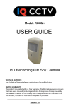
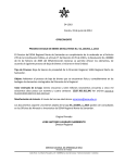
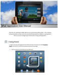
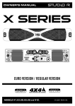
THIS FORESIGHT SPORTS GC2 SMART CAMERA SYSTEM PACKAGE INCLUDES: Welcome to the revolution. Thank you for choosing the GC2 by Foresight Sports. We listened to what you wanted - and created the most versatile, mobile, and accurate ball flight analysis solution available today. GC2 Smart Camera System Power Adapter/Cable USB Cable Input 100-240VAC/50-60 Hz Output 15VDC/2.4 Amps Spare Flash Module © 2012-2013 Foresight Sports Foresight Sports may have patents, patent applications, trademarks, copyrights, or other intellectual property rights covering subject matter in this document. Except as expressly provided in any written license agreement from Foresight Sports, the furnishing of this document does not give you any license to these patents, trademarks, copyrights, or other intellectual property. The GC2 has been designed to provide you with years of incredible performance. From range practice to full immersion simulation, whether for education or entertainment, the GC2 will truly change your game. This user manual will help you better understand the proper set-up, operation, and care of your new GC2. Please read it carefully and refer to it should an issue arise during use. If you need more assistance, please contact our customer service team for prompt personal attention. Feature Overview A Tracking Cameras high speed optical cameras for ball placement and tracking B Flash Module replaceable high intensity strobe light for tracking LEFT SIDE VIEW A tracking cameras B interchangeable flash module G C Audio Speaker provides audio announcement of launch data C audio speaker D Audio Line Out connector to enable external, amplified speaker connection D audio line out E LCD wire stand used to adjust the viewing angle of the display screen E LCD wire stand F Foot Stand must be fully deployed (rotated) to ensure the device is properly positioned; also serves as a latch to secure the device in the closed (folded) position G LCD Display displays ball placement graphic, ball flight data and other user information H USB Port connector for USB cable (supplied) to connect to external PC (optional) I Accessory Port used for factory troubleshooting J Power Port connector for the power adapter (supplied) to recharge the batter or to operate on external power K LED indicator L Power Button M Key N Keys O Key 2 LCD display RIGHT SIDE VIEW F foot stand H USB port indicates whether a ball is outside of the hitting zone (blinking red) or within the hitting zone (constant green) I accessory port J power port turns the device on/off CONTROL PANEL VIEW used to navigate and select display options P Display Backlight illuminates the display for better viewing in low light situations Q Audio Volume turns sound on/off and adjusts volume to three levels: low, medium and high Q audio volume K LED indicator L power button M back key N cursor keys O enter key P display backlight 3 Getting Started 1 3 TURNING POWER ON / OFF OPENING THE GC2 Deploy the foot stand by rotating it 180 degrees until it is directly below the base of the GC2. Be sure to rotate stand until it comes to a stop. Open the top of the device by rotating top cover back until it comes to a stop. NOTE: Make sure the top is completely rotated to insure proper operation. To turn power on, press and release the Power Button key. When the power button is pressed to turn the GC2 ON, the LED near the keypad will turn green. Software and hardware versions of the GC2 will be momentarily displayed. The LED indicator will blink red and display the ball placement graphic to indicate the GC2 is ready to track a shot as soon as a golf ball is placed within the field of view. To turn power off, press and release the Power Button key again. The device will initiate its shutdown sequence, and the display screen will read “GC2 Now Shutting Down.” 2 ELEVATING THE DISPLAY SCREEN (OPTIONAL) The Display Screen may be raised by pushing it upward and deploying the wire stand behind it. Press the screen upward by extending your index finger through the opening in the bottom of the device to raise the screen. Release the wire stand from the top of the Display Screen and rotate it downward, placing the wire elbows in one of the three sets of indents in the bottom of the device. PLEASE NOTE: Raising the Display Screen improves the viewing angle and reduces glare outdoors. Your new GC2 Smart Camera System was provided FULLY CHARGED and ready for use. PLEASE FULLY USE THE FIRST CHARGE ON THE DEVICE PRIOR TO CHARGING WITH THE PROVIDED POWER CORD AND ADAPTER. 4 5 Selecting System Options 3 CHANGING THE CURRENT SYSTEM SETTING To change the current setting of the selected option, press the OK key until the desired setting appears. SYSTEM OPTIONS 1 Once the GC2 is ON and has fully completed its boot-up sequence, the player’s preferred SYSTEM OPTIONS can be changed. To begin, select the “OK” Button on the front LCD Panel. Velocity Unit MPH Distance Unit YDS Ball Spin Mode TOTAL About... NOTE: Selecting the BACK button will return you to ball-find/ play mode at any time. 2 NAVIGATING THE SYSTEM OPTIONS SCREEN The system options menu should now appear on the LCD screen. OPTIONS CHART VELOCITY UNIT DISTANCE UNIT BALL SPIN MODE displays velocity in: displays distance in: displays spin values of: MPH M/S KPH YDS FT MTS Total Back (Miles per Hour) (Meters per Second) (Kilometers per Hour) (Yards) (Feet) (Meters SYSTEM OPTIONS Velocity Unit MPH Distance Unit YDS Ball Spin Mode TOTAL To select an option, use the UP or DOWN ARROW keys. With the desired settings selected, simply select the BACK button to return to the ball-find/play mode. 4 About... Your new settings have been saved and will now be displayed during play. SYSTEM OPTIONS Velocity Unit MPH Distance Uni Unit YDS Ball Spin Mode TOTAL About... The selected option will be highlighted as shown. NOTE: The “About” Option can be selected to view the device’s firmware software version and battery charge information. 6 7 Ball Placement and Hitting 1 Ball-find display on LCD Ball Placement GC2 The GC2’s on-screen placement aid displays the hitting zone relative to the GC2. The ball must be placed within this hitting GC2 zone to correctly track the ball in flight. The display will also show the position of the ball if there is a ball in the camera’s field of view. The LED indicator will blink red if there is no ball LOOKING FOR A BALL within the hitting zone, or if a ball is not being identified within the hitting zone. When the ball is properly placed 20” Ball-find display on LCD within the hitting zone, the LED indicator turns green and the launch monitor is ready for a LEFT HANDED ZONE Ball placement will be indicated with a solid circle on the screen. RIGHT HANDED ZONE GC2 shot to be hit. LOOKING FOR A BALL FLASHING RED LED indicates no ball or ball out of hitting zone. SOLID GREEN LED indicates ball inside of hitting zone. 2 Hitting a Shot Once the ball is placed within the hitting zone and the LED indicator has turned green, a shot may be hit. Upon launch, the GC2 will capture images of the ball in flight, calculate and display the launch parameters. If sound is enabled, the launch parameters will also be announced audibly. 8 9 Replacing the Flash Unit The GC2 has a replaceable flash unit installed. Depending on usage, this unit should operate reliably for one to two years. If the flash unit requires replacement, it can be easily removed and replaced. Safety Instructions Please read the safety and warning information below before operating your new GC2 smart camera system: If foreign objects or water has entered the device, disconnect the device from external power and turn the power off. Continued use in this state can cause fire or electric shock. To replace the flash unit: 1 Make sure LCD screen is fully lowered into base prior to removing flash unit. DO NOT disassemble, change or attempt to repair the device. This could result in electric shock and will void the manufacturer’s warranty. If the flash module needs to be replaced, follow the directions provided in this user manual. 2 Using a flat head screwdriver (not provided), loosen the two screws connecting the flash unit to the device housing until the screws spin freely. DO NOT use this device in environments where high humidity, smoke or dust is present. NOTE: Screws are attached to the removable flash unit. DO NOT attempt to pull screws out by themselves. To avoid possible injury, DO NOT look directly at the device while the flash is in use. 3 Once both screws spin freely, grab both screws firmly and gently pull flash unit from housing. If necessary, pull against screws in an alternating pattern to free flash unit from device. The GC2 has been designed to withstand ball impact. However, if the device enclosure or LCD display has been damaged due to a ball impact or for any other reason, turn power off and discontinue use. Use only the power adapter that came with the device. Using any other power adapter or charger may cause damage to the GC2 or battery, and may cause fire or injury. 4 Align new flash unit with attached screws to device housing. MAKE SURE PINS ON BACK OF FLASH UNIT ARE PROPERLY ALIGNED WITH PIN RECEPTACLES IN DEVICE. Gently but firmly insert flash unit into housing. 5 Secure new flash unit by tightening both screws until snug. DO NOT OVER-TIGHTEN SCREWS. 10 Unless directly authorized by Foresight Sports, DO NOT attempt to replace the battery in the device. Doing so will void all warranties, and may cause injury. For battery replacement authorization and instruction, please contact Foresight Sports. Need a new flash? New flash modules may be purchased by contacting your Foresight Sports retailer or representative today. The GC2 uses two digital cameras that are precisely calibrated. Do not drop or subject the device to any impacts that may cause shock. After use, always store the GC2 in a safe, dry, and dust-free environment. 11 Connecting the GC2 To insure uninterrupted performance and long-term use of your GC2, please follow these best practices when connecting power, accessory or USB cables to the device: Recharging the GC2 Please use the power adapter provided to charge the GC2. The GC2’s NiMH battery requires 4 hours to fully recharge. The battery in your GC2 has been designed to provide safe, reliable operation. However, the life of your GC2 battery and its ability to hold an adequate charge is dependent upon a regular routine of fully discharging and recharging the battery. Without regularly performing this discharge/recharge routine, the GC2’s battery life expectancy can be compromised significantly. IMPORTANT! Your GC2 battery should be fully discharged and recharged at least once a month. This includes batteries in storage, as well as batteries on GC2 units operating on continuous AC power. DO 12 DO NOT Carefully plug power cord, accessory or USB cable into the device BEFORE powering on the unit and beginning use. DO NOT plug the power cord, accessory or USB cable into the device AFTER powering on the unit and beginning use. Make sure the smaller connection on the USB cable is the one inserted into the device. DO NOT attempt to close the GC2 while the USB cable is still inserted. This may cause severe damage to both the cable and the device. Failure to abide by this routine may cause the battery to lose its ability to recharge or hold an adequate charge, and will require replacement at the customer’s expense. Storing the GC2 Prior to storing your GC2, always make sure the device is powered off and properly closed and latched. Foresight Sports strongly recommends storing the GC2 in a cool, dry environment in its original foam-lined box to prevent damage. Always disconnect cables before closing device. 1 2 3 13 Troubleshooting Guide Encountering an issue? Use this troubleshooting guide to help diagnose and resolve the problem. ISSUE: The device does not display “ready to hit” (green LED active) when a ball is placed in the hitting zone • Make sure the ball is visible by the cameras (i.e. no deep grass, etc.). • Confirm the ball is appearing within the hitting area on the LCD display. • Make sure the foot stand is completely deployed. • Make sure the top of the device (where cameras are located) is fully opened. • Make sure the foot stand is completely deployed. • Make sure the top of the device where tracking cameras are located is fully opened. • Verify the flash is operating when a ball is struck. This may be difficult to observe by the hitter - a separate observer is recommended to watch the flash while the hitter strikes the ball. • If the flash is non-operational, please refer to this manual for replacement instructions. • LCD displays a message on screen asking me to contact the factory Make a copy of the message, and call Foresight Sports customer support for further assistance. For additional troubleshooting assistance, please go to www.foresightsports.com. ISSUE: The device will not power on The ball placement aid is not appearing on the LCD display SUGGESTION: • • If the device does not power up while plugged into the charger, verify that the correct charger is being used (15V output, minimum of 36W). • If the charger is the correct one, and the device still does not power up, please go to www.foresightsports.com for details on how to return for repair. • The placement aid is visible only when the light is flashing red, and a ball is recognized in the area of the launch monitor. • If the light is green, then a ball is ready to be struck, and the previous shot results are displayed. • 14 Ensure the battery is charged up. First, test with the device plugged into the charger and make sure it comes on. If it does, then let the battery charge up for a minimum of 4 hours before running on batteries. If there is no ball in the camera’s view, then the previous shot results are displayed. SUGGESTION: The device appears to display inaccurate data The device does not track ball flight IMPORTANT Ball strikes may cause severe damage to the device that require repair or replacement. Foresight Sports recommends the use of a protective cradle during operation. 15 Product Specifications TECHNOLOGY: Stereoscopic high-speed digitial camera tracking system. GC2 Dimensons 5.5”W x 10”L x 3”T (Closed) Weight: 3.8 lbs (1.7 kg) Data Interface: USB/Bluetooth Battery: 6-8 hour Rechargeable NiMH Measured Data: Ball Speed, Side spin, Azimuth, Back Spin, Launch Angle, Total Spin Calculated Data: Carry Distance, Total distance Questions? CAPTURE RANGE: Ball Speed: 2.0 - 200.0+ mph Distance: 8 inches - 500+ yds Launch Angle: 70.0 degrees ACCURACY TOLERANCE: Vertical Launch Angle +/- 0.2 degrees Ball Speed: +/- 0.5 mph Back Spin: +/- 50 rpm Side Spin: +/- 50 rpm Azimuth: +/- 1.0 degrees 16 We’re here to help. For product related issues or questions, please contact our customer support team at 858.880.0179 or online at [email protected] © 2012-2013 Foresight Sports Printed in the USA gc2um-2012-03 www.foresightsports.com