1
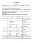
TFM Input Tester User Manual
Park Signalling
Limited
www.park-signalling.co.uk
PS/PSL-RD-305/MAN/005 Issue 3
Park Signalling Limited ©2006
Page 1 of 6
1.
INTRODUCTION
1.1.
Purpose
This document provides instructions on the use of Park Signalling’s ST 201 TFM Input Tester
and the ST 202 Power Adaptor.
1.2.
Scope
This document details how to use the TFM Input Tester, and interpret its results.
Note that information on obtaining authorisation / permission to work on a live signalling
system is beyond this document’s scope.
1.3.
Abbreviations
SSI
TFM
TFMIT
2.
Solid State Interlocking
Trackside Functional Module (part of SSI)
TFM Input Tester
STORAGE AND HANDLING
The TFMIT should be stored in a dry environment with a temperature range of 0-35°c.
It is recommended that the TFMIT’s 75-way plug and socket are connected together when not
in use, in order to limit any damage to or dirtying of the connector contacts.
The TFMIT should not be carried by its flying leads.
As the TFMIT is electronic equipment, please dispose of it responsibly when it is life-expired.
PS/PSL-RD-305/MAN/005 Issue 3
Park Signalling Limited ©2006
Page 2 of 6
3.
OPERATION
3.1.
Pre test checks
1. Ensure that the TFMIT is not visually damaged, and is in calibration (the calibration label
is on the side of the unit, and must be intact for the calibration to be valid).
2. Ensure that the contacts in the TFMIT’s 75-way connectors are clean and undamaged.
3. Ensure that the TFMIT is not and will not be exposed to rain, sleet or snow.
4. Ensure that the TFM to be tested is one of the following:
• Alstom Mk3 Signal Module (SS3303),
• Alstom Mk3 Points Module (SS3103),
• Alstom Mk4 Signal Module (SS3304),
• Westinghouse MkIIIA Signal Module (E25051/1),
• Westinghouse MkIIIA Points Module (E25050/1).
3.2.
Connections & settings
Care must be taken to ensure that 75-way connectors’ thumb-screws are not over-tightened or
unevenly tightened.
Although the TFMIT has no exposed conductors, care must be taken due to the presence of
110V a.c. in the test environment.
3.2.1. On-site procedure
1. If appropriate, hang the TFMIT from the TFM’s handle.
2. Ensure that the TFMIT’s power switch is in the ‘OFF’ position.
3. Set the ALS/WRS switch to its appropriate position (for Alstom or Westinghouse). Note
that the test results may be incorrect if the ALS-WRS switch is in the wrong position.
4. Remove power from the TFM to be tested (e.g. by removing its location case fuse).
5. Disconnect the location case’s 75-way socket from the TFM to be tested.
6. Connect the location case’s 75-way socket (which has just been disconnected from the
TFM) to the TFMIT’s 75-way plug.
7. Connect the TFMIT’s 75-way socket to the TFM being tested.
8. Apply power to the TFMIT (e.g. by replacing its location case fuse).
3.2.2. Workshop procedure
1.
2.
3.
4.
5.
6.
If appropriate, hang the TFMIT from the TFM’s handle.
Ensure that the TFMIT’s power switch is in the ‘OFF’ position.
Set the ALS/WRS switch to its appropriate position (for Alstom or Westinghouse).
Connect the TFMIT’s 75-way socket to the TFM being tested.
Connect the TFMIT Power Adaptor’s 75-way socket to the TFMIT’s 75-way plug.
Connect the TFMIT Power Adaptor to a 110V a.c. supply (note that the earth lead is not
used by the TFMIT, but is connected through to the TFM to allow earthing of its chassis).
PS/PSL-RD-305/MAN/005 Issue 3
Park Signalling Limited ©2006
Page 3 of 6
3.3.
Running the test
The TFMIT should not be left unattended while it is powered on.
1. Set the TFMIT’s power switch to the ‘ON’ position; the blue ‘testing’ indication should
light.
The TFMIT will automatically detect whether the TFM being tested is a Points or Signal
module, and illuminate its relevant blue indication.
2. Wait for the testing indication to extinguish, and the pass/fail indication to light (this can
take up to 60 seconds).
3. To run the test again, press the TFMIT’s reset button.
PS/PSL-RD-305/MAN/005 Issue 3
Park Signalling Limited ©2006
Page 4 of 6
3.4.
Results
The TFMIT’s Pass/Fail indication gives an overall result for the test. Table 3-1 describes the
meaning of the result with a recommended course of action.
Indication
Colour
Green
Yellow
Red
Meaning
Action
All tests on the TFM have passed.
None of the tests have failed. However, at least
one of the contact sensing input tests has
reported a caution (see Table 3-2).
Either: Communications cannot be established
with the TFM under test,
or: At least one of the tests on the TFM has
failed.
None.
As at least one TFM input is beginning to fail,
consider replacing the module if a spare is
available.
Replace / repair TFM.
Table 3-1 Pass/Fail Indication
Each contact sensing input of the TFM (Inputs 0-5 for a signal module, or inputs 0-3 and
points X & Y for a points module) has a result indication.
Indication Colour
Green
Yellow
Red
Meaning
Pass: the input has not degraded.
Caution: the input has partially degraded but should not affect the
signalling system.
Fail: the input has degraded and may affect the signalling system.
Table 3-2 Contact Sensing Input Test Result Indication
The contact sensing code drives (BXI/NXI and BXE/NXE) each have a test result indication.
Indication Colour
Green
Red
Meaning
Pass: the code drive has not degraded.
Fail: the code drive has degraded and may affect the signalling system.
Table 3-3 Code Drive Test Result Indication
PS/PSL-RD-305/MAN/005 Issue 3
Park Signalling Limited ©2006
Page 5 of 6
3.5.
Disconnections
3.5.1. On-site procedure
1.
2.
3.
4.
5.
6.
Set the TFMIT’s power switch to the ‘OFF’ position.
Remove power from the TFMIT (e.g. by removing its location case fuse).
Disconnect the TFMIT from the TFM and the location case’s 75-way socket.
If appropriate, replace the TFM.
Connect the TFM to the location case’s relevant 75-way socket.
Apply power to the TFM (e.g. by replacing its location case fuse), and ensure that it
functions correctly.
7. Connect together the TFMIT’s 75-way plug and socket, in order to limit any damage to or
dirtying of the connector contacts.
3.5.2. Workshop procedure
1.
2.
3.
4.
Set the TFMIT’s power switch to the ‘OFF’ position.
Disconnect the TFMIT Power Adaptor from the 110V supply and the TFMIT.
Disconnect the TFMIT from the TFM.
Connect together the TFMIT’s 75-way plug and socket, in order to limit any damage to or
dirtying of the connector contacts.
PS/PSL-RD-305/MAN/005 Issue 3
Park Signalling Limited ©2006
Page 6 of 6