1
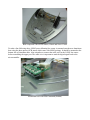
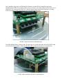
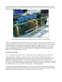
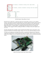
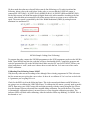
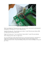
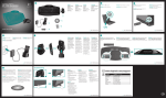
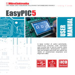
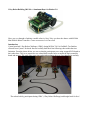
1 Day Robot Building (MC40A + Aluminum Base) for Edubot 2.0
Have you ever thought of making a mobile robot in 1 day? Now you have the chance with MC40A
Mini Mobile Robot Controller + some accessories. Let’s have fun!
Introduction
Cytron launched 1 Day Robot Challenge (1DRC) during MURoC 2011 in UniMAP. Ten finalists
selected from Cytron’s facebook fans successfully built their line following robot within the time
limitation. From the photos below, we can see that the participants were using scrapped PCB board as
their robot base. They were required to use a hand drill to make holes to mount the main controller
board and motors. This took quite some time and might endanger the user if not handled it carefully.
The robots built by participants during 1DRC (1 Day Robot Challenge) and bought back for free!
Making holes on scrapped PCB board
To help users build their robot in an easier way, Cytron has come out with a new aluminium base which
only requires users to screw in everything without the need to modify. This brand new aluminium robot
base also comes with a pretty COOL shape. It is designed to support:
• SK40C PIC Starter Kit
• MC40A Mini Mobile Robot Controller
• Arduino main boards, Duemilanove or Uno
• LSS05 Auto-calibrating Line Sensor
• SPG10 DC Geared Motor
• MD10C, 10A motor driver
Furthermore, users are allowed to install extra sensors such as limit switch to the mobile robot to
further improve the robot operation. Of course you can easily modify this robot base to fit any
controller, sensor and motor that you wish to use.
In this article, I’m going to guide you to assemble a mobile robot using MC40A and make it a simple
line following robot.
How to Assemble?
Before you start assembling a mobile robot, it is always good to plan ahead so that you have a rough
idea how your robot is going to operate. Base on your idea, come out with a sketch or design of your
robot. Next, prepare the components and materials that are needed. After that, start building the robot
from the base to the top and of course from the basic to the details. Cytron calls it Robot. Head to Toe.
As for this mobile robot, there are a few components that we need to prepare such as MC40A Mini
Mobile Robot Controller, the new aluminium base, LSS05 Auto-calibrating Line Sensor, spacers (or
PCB stands), screws, SPG-10 micro metal geared motor and WL-POL-4610 wheel.
Mobile Robot Parts
If you are getting yourself an Edubot 2.0, the mobile robot is ready assembled. If you want to build this
yourself please ensure you have all the parts:
• Aluminium Base + SPG10-150K MicroGear Motor (1 pair) + Wheel (1 pair) + Screw Caster + 4 tiny
screw to mount Motor, which you can get all this in 1 set at here, Aluminium Robot Chassis Complete
Set
• MC40A, Mini Mobile Robot Controller Combo 1
• 4 set of PCB Stand, 20mm S/S
• 40cm of wire, preferable multicore.
To setup a robot, we usually start building from the base. Mount the motor onto the base. You are
encouraged to get a magnet to hold the screws while assembling the motor as some of the screws used
are very TINY! Next, assemble the front caster by inserting the screw to the hole at the front and lock it
with the round cap hex nut. After that, put on the tire to the motor and then the base is complete. Don’t
forget to solder wires to SPG10 Motor terminal Wire length should be around 10cm.
Base completed with SPG10 motors, Wheel and Screw Castor
To make a line following robot, LSS05 auto-calibrating line sensor is mounted onto the new aluminium
base using the short spacers (PCB stand) which come with LSS05 package. It should be mounted at the
bottom side of aluminium base. Also remember to connect the cable wire for the LSS05 line sensor
before assembling the upper part. The cable wire is important to send the digital signal back to the
microcontroller.
Aluminium base with LSS05 mounted (bottom)
Next, install the long spacers (PCB Stand S/S 20mm) to mount MC40A controller board to the
aluminium base. Make sure you have solder every accessories you want to add to MC40A such as 2×8
Character LCD, connector for UART, etc. And also power it up to ensure basic function is working,
before assembling so that you need not waste time troubleshooting later.
MC40A Controller Board on Aluminium base
Your Mini Mobile Robot is almost ready. The next step is to connect the other end of the LSS05 cable
wire to the MC40A controller. Make sure that the cable is connected securely to avoid data loss.
LSS05 cable connected to MC40A Controller Board
Lastly, insert the motor wire into the motor terminal on the board and again make sure it is securely
screwed. You need not worry about the terminal connection of DC motor because the direction can be
controlled in the software later.
Motor terminal cable connected to “RIGHT M” and “LEFT M” terminal (Blue)
Finally, your Mini Mobile Robot hardware is done. After supply it with a power source and do some
software programming, it’s ready to go. As for the power source, you have 2 choices. You can power it
up using a battery or an adapter power supply. Please ensure the voltage is between 7V to 12V. Two
Cells Li-Po battery is a good choice as the voltage is within the operating range. If you are using
battery, BE CAREFUL NOT TO CUT BOTH BATTERY TERMINALS AT THE SAME TIME. IT
MAY CAUSE AN EXPLOSION, for Li-Po
Line Following Coding
Yes! I’ve assembled my robot but why is it still not moving? Ever heard this question before? It’s
commonly asked by beginners. A robot is a machine which consists of hardware and software
components. We have completed the hardware part, so now we need to work on the software. Why?
Well, besides building the hardware, we also need to program the software as the robot needs a
“BRAIN” to think. Programming is a way to give the robot the instructions or commands to do the task
we required. A robot needs both hardware and software components to function. Now that we already
have the hardware, let’s move on to the robot’s “brain”, i.e. the programming.
Cytron provides the line following sample code for MC40A Mini Mobile Robot and this code can be
downloaded for FREE! Please log on to http://www.cytron.com.my/viewProduct.php?pcode=MC40A
and download MC40A Sample Source Code 10Nov 2010 for your reference.
MC40A Sample Coding (Motor Control)
Referring to the coding above, to make the robot move forward, MR_1 & ML_2 are set to HIGH
(Logic 1). The purpose is to make the right wheel move clockwise and the left wheel counter clockwise
. By doing this, the robot will move forward. If the robot moves backward or in any other direction,
please check which motor is moving in the wrong direction and then change the motor terminal, i.e.
change the positive(+) with the negative(-) terminal of the same motor. Or, you may change the
software as I have suggested earlier by making the HIGH(1) to LOW(0) for the motor required, and
vice versa.
One more important step to remember. Always check the power that the motor is using. Here, we are
using SPG10 which the recommended supply voltage is 5V. So we may connect the jumper 5 (JP5) to
Vin. But if you’re planning to use higher power motor or external power for motor, you will need to
connect the external power to Vmotor terminal and connect the jumper 5 (JP5) to Vmotor. Please refer
to MC40A User Manual for more information about the power supply selection and absolute maximum
ratings.
Motor Power Input Terminal and Selection Jumper
We have made the robot move but still it does not do line following yet. To make it perform line
following, please refer to the code below. In the code, we can see that the LSS05 line sensor is
connected to LEFT (RA3), M_LEFT (RA4), MIDDLE (RA5), M_RIGHT (RE0) and RIGHT (RE1).
Each of this sensors will send data output in digital form to the microcontroller according to the line
sensed. Afterwhich the microcontroller will tell the motor which way to turn or move and also the
speed. The motor speed is controlled by the Pulse Width Modulation (PWM) by setting between
minimum 0 to maximum 255.
MC40A Sample Coding (Line Following)
To program the robot, connect the UIC00B programmer to the ICSP programmer socket on the MC40A
board. Open MPLAB and also the code that you have downloaded earlier. Compile the program and
write the generated hex file to the MC40A board. Make sure the PIC used is PIC16F887. Before your
robot learns how to ‘walk’, make sure it knows how to watch the line. Let’s move on to line sensor
LSS05 calibration.
Calibrating Line Following Sensor LSS05
Why does my robot not run according to line although I have already programmed it? This is because
the line sensor may not giving the correct value. So how do we calibrate it? Let’s see how to deal with
it. I guarantee you are going to love it.
Check for the RED circle in the following figure. This is the external push button on MC40A that we
are going to use to calibrate the LSS05 line sensor. To calibrate the line sensor, you only need to push it
ONCE, then swing your LSS05 sensor left and right repeatedly with the sensor facing the line. Please
keep the distance between robot and floor constant during calibration. Do not lift the base. The sensor
is automatically calibrated so there is no need for us to worry about the calibration procedure. The
indicator LEDs will blink while calibrating. After the indicator LEDs stop blinking, it’s DONE. Now it
has learned to ‘see’.
LSS05 Calibration Push Button
Well, it’s not finished yet. The sensor also comes with extra 2 modes, namely dark line following mode
and bright line following mode. It’s easy to change the mode.
Dark line following mode – Press the button twice within 1.5 second. Then the sensor indicator LEDs
will light up when it detects a dark surface.
Bright line following mode – Press the push button 3 times within 1.5 second. The sensor indicator
LEDs with light up when it detects a bright surface.
Now your mobile robot is fully functional and ready to go. Put it on the line and test it. Sometimes you
might need to recalibrate the sensor if the sensor senses dirt on the line surface during previous
calibration. Well, that’s all for 1 Day Robot Building. Wish you have learned something new. Enjoy and
give it a try!