1
1
2
3
4
1
2
3
4
5
6
7
8
9
10
1
2
3
4
5
6
7
8
9
10
11
12
13
14
15
16
{F}
B
{F}
B
{F}
B
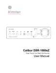
Calibur DVMRe
Digital Video Multiplexer Recorder
User Manual
WARNING!
To prevent fire and electric shock, do not expose this product to rain or moisture.
!
The lightning flash with the arrowhead symbol,
within an equilateral triangle, is intended to alert
the user to the presence of uninsulated
"dangerous voltage" within the products enclosure
that maybe of sufficient magnitude to constitute a
risk of electric shock to persons.
The exclamation point, within an equilateral
triangle, is intended to alert the user to the
presence of important operating and maintenance
(servicing) instructions in the literature
accompanying the product.
CAUTION!
To prevent electric shock, do not remove cover.
No user serviceable components inside. Refer
servicing to qualified service personnel.
!
CAUTION! Lithium Battery
ATTENTION
Danger of explosion if battery is
incorrectly replaced. Replace only
with the same or equivalent type
recommended by the
manufacturer.
This product contains a recyclable lithium battery.
It may be illegal to dispose of this battery
improperly under local, state, or federal laws.
Check with your local waste management officials
for disposal and recycling options.
CAUTION!
Electrostatic-Sensitive Device!
Use proper CMOS and MOSFET handing precautions, including approved
grounded wrists straps, etc., to avoid damage to this unit or its internal
components, from electric discharge.
WARNING!
This equipment generates, uses and can radiate radio frequency energy, and if not installed and used
in accordance with the instructions in this manual, may cause interference to radio communications. It
has been tested and found to comply with the limits for a Class A computing device pursuant to subpart
J of part 15 of FCC rules which are designed to provide reasonable protection against such
interference when operated in a commercial environment. This equipment has also been tested and
found to comply with the requirements for a CE Class A device and TUV safety standards.
Operation of this equipment in a residential area may cause interference, in which case the user is
required to take all measures that are necessary, at the user's expense, to correct the interference.
Calibur DVMRe
2
0150-0138D
IMPORTANT INFORMATION
Software and/or firmware is furnished to the purchaser under a license for use on a single system.
Software and/or firmware included with this equipment are the sole proprietary property of, confidential
to, and copyrighted by Kalatel, Corvallis, Oregon, USA. The software/firmware are not to be copied or
disclosed in any manner without the express written consent of Kalatel.
All information and specifications furnished by Kalatel are believed to be accurate and reliable. No
responsibility is assumed by Kalatel for neither its use nor any infringements of rights of third parties
that may result from its use. No license is granted by implication or otherwise under any patent or
patent rights of Kalatel.
The CALIBUR™ brand name and product model numbers are the property of Kalatel.
COPYRIGHT, 2001: The contents of this manual may not be copied or reproduced in any manner or
form without the prior written consent of Kalatel.
0150-0138D
3
Calibur DVMRe
Contents
1
FEATURES, CONNECTIONS, AND SETUP ....................................................7
1.1
1.2
1.3
1.4
1.5
1.6
1.7
1.8
1.9
1.10
2
2.1
2.2
2.3
2.4
2.5
2.6
2.7
3
3.1
3.2
3.3
3.4
4
4.1
4.2
4.3
4.4
4.5
4.6
4.7
5
5.1
5.2
5.3
Products Featured In This Manual .................................................................... 7
Product Description............................................................................................ 7
Passwords........................................................................................................... 8
Unpacking ........................................................................................................... 9
Installation Environment .................................................................................... 9
The Rear Panel.................................................................................................... 9
Connections ...................................................................................................... 10
Alarm I/O Port.................................................................................................... 12
Power-Up ........................................................................................................... 14
Minimum Recommended Menu Setup ............................................................ 15
USER OPERATIONS ...............................................................................17
Principal Operating Modes .............................................................................. 17
Simplex Vs. Duplex........................................................................................... 17
The Front Panel................................................................................................. 17
Recording .......................................................................................................... 17
Playback ............................................................................................................ 20
Live Multiscreen Mode ..................................................................................... 23
Running A Macro .............................................................................................. 25
DISPLAY OPTIONS ................................................................................27
Available Multiscreen Displays ....................................................................... 27
Active Cameos .................................................................................................. 27
Sequencing ....................................................................................................... 28
On-screen Indicators ........................................................................................ 29
ALARMS ..............................................................................................31
Alarm Input........................................................................................................ 31
Alarm Output..................................................................................................... 31
Silence And Acknowledge ............................................................................... 31
On-screen Displays During Alarms................................................................. 31
Alarm Operations During Playback................................................................. 32
Alarm History Box............................................................................................. 32
Searching For Recorded Alarms ..................................................................... 32
SEARCHING AND ARCHIVING ..................................................................33
Defining Search Type ....................................................................................... 33
Defining Search Criteria ................................................................................... 33
Search Results.................................................................................................. 35
Calibur DVMRe
4
0150-0138D
6
MENU SYSTEM OVERVIEW .....................................................................37
6.1
6.2
6.3
6.4
6.5
7
Menu Notation In This Manual ......................................................................... 37
Accessing The Menu System .......................................................................... 37
Available Menus................................................................................................ 37
Menus In This Manual....................................................................................... 38
Navigating The Menu System .......................................................................... 38
THE MAIN MENU ...................................................................................39
7.1
7.2
7.3
7.4
7.5
7.6
7.7
7.8
7.9
7.10
7.11
7.12
7.13
8
8.1
8.2
8.3
9
9.1
9.2
9.3
Main Menu Overview ........................................................................................ 39
Time/Date........................................................................................................... 39
Sequencing ....................................................................................................... 41
Record ............................................................................................................... 41
Alarms................................................................................................................ 45
Macro ................................................................................................................. 49
Motion Detection............................................................................................... 51
Camera Setup.................................................................................................... 53
Video Archive Setup ......................................................................................... 56
Communications............................................................................................... 58
Front Panel Lock............................................................................................... 60
Factory Settings................................................................................................ 60
Passwords......................................................................................................... 60
THE QUICKINSTALL MENU .....................................................................61
QuickInstall Menu Overview ............................................................................ 61
Monitor Setup.................................................................................................... 61
ADM (Auto Delete Mode) .................................................................................. 62
THE OPERATOR & SYSTEMVIEW MENUS ................................................63
The Operator Menu........................................................................................... 63
The SystemView Menu ..................................................................................... 63
The View Screens ............................................................................................. 64
10 TECHNICAL SPECIFICATIONS ..................................................................67
11 TEXT INSERTION PROTOCOL ..................................................................69
11.1 Message Structure............................................................................................ 69
11.2 Message Type ................................................................................................... 69
11.3 Event Field......................................................................................................... 69
12 RS-232 REMOTE PROTOCOL ................................................................71
12.1 Remote Front Panel Simulations..................................................................... 71
12.2 Remote Data And CommandsData Structure................................................. 72
13 MACRO TABLES ...................................................................................77
13.1 Macro Functions Table..................................................................................... 77
0150-0138D
5
Calibur DVMRe
13.2 Scheduled Macro Table.................................................................................... 78
14 WARRANTY AND SERVICE......................................................................79
14.1 Factory Service ................................................................................................. 79
14.2 Warranty ............................................................................................................ 80
Calibur DVMRe
6
0150-0138D
1
Features, Connections, and Setup
1.1 Products Featured In This Manual
DVMRe-4CS: Digital Video Multiplexer Recorder, Four-Channel, Color, Simplex.
DVMRe-4CD: Digital Video Multiplexer Recorder, Four-Channel, Color, Duplex.
DVMRe-10CD: Digital Video Multiplexer Recorder, Ten-Channel, Color, Duplex.
DVMRe-16CS: Digital Video Multiplexer Recorder, Sixteen-Channel, Color, Simplex.
DVMRe-16CD: Digital Video Multiplexer Recorder, Sixteen-Channel, Color, Duplex.
Key To Model Numbers
1. DVMRe: Digital Video Multiplexer Recorder, Ethernet capable.
2. 4, 10, or 16: Maximum number of camera inputs.
DVMRe
16
C
D
1
2
3
4
3. C: Color
4. D: Duplex. S: Simplex
1.2 Product Description
The DVMRe is a video multiplexer capable of recording multiple cameras simultaneously to an internal
hard disk. Digital recording improves playback quality over time-lapse VCRs, and eliminates the hassle
of changing tapes. The unit can be programmed to record continuously by overwriting the oldest
recorded data. The unit also allows access to stored video and live camera images via an ethernet
connection. Programmable search features eliminates time consuming Fast Forwarding or Rewinding
of tapes, searching for critical data. Search for images or events by alarm, time, date, camera number
and ASCII cash register or ATM text. Dual monitor outputs allow the user to view separate
Multiscreen and Full Screen displays simultaneously.
Caution! This units primary purpose is to furnish video multiplexing and recording with a
multiscreen display. Although the unit has alarm handling and motion detection functions, they
are considered secondary features. This unit should not be the only alarm device on site.
Features
•
Simple operator menus and easy to use front panel controls.
•
Digital recording to internal hard disk.
•
Activity and Intrusion Motion Detection.
•
Independent monitor control.
•
Full Screen and Multiscreen camera sequencing with programmable sequence list and dwell
times.
•
Video Freeze and Electronic Zoom with digital pan and tilt.
•
Covert camera recording (recording without display).
•
Alarm Handling with Alarm History Log
•
User programmable macros, with a macro scheduling function to run the macro at a
predetermined time.
0150-0138D
-7-
Calibur DVMRe
•
User programmable submacros for RS-232 external device control.
•
Daylight savings time change function.
•
Master/Slave time clock control via the RS-485 network.
•
Remote programming and control through the RS-232, RS-485 and Ethernet ports.
•
Video Archiving via the units SCSI port to DAT, AIT, or CD.
•
Playback of recorded video via ethernet or modem.
•
Live video viewing via ethernet or modem.
•
Downloading video to PC via ethernet or modem.
1.3 Passwords
Passwords are provided to limit access to menus and certain functions. Two levels of password
security are provided:
•
Operator: Limited menu access, only Operator and System View menus are available.
•
Installer: Complete menu access.
As a security measure, it is recommended that the Operator and Installer passwords be changed after
installation is complete (see section 7.13). Store the passwords in the administrators secure files.
Default Passwords
Four-Channel Units
Password
Type
Access
Level
Operator
Operator
Provides access to the Operator
and SystemView menus.
Yes
Installer
Installer
Provides access to all on-screen
menus.
Yes
3444
Factory
Defaults
Installer
Resets the multiplexer to the
factory defaults.
No
4111
Language
Installer
Provides access to the On-screen
Language menu.
No
1414
Changeable
by user?
Default
Password
Function
Changeable
by user?
Default
Password
Ten and Sixteen-Channel Units
Password
Type
Access
Level
Operator
Operator
Provides access to the Operator
and SystemView menus.
Yes
Installer
Installer
Provides access to all on-screen
menus.
Yes
3 4 77
Factory
Defaults
Installer
Resets the multiplexer to the
factory defaults.
No
81 1 1
Language
Installer
Provides access to the On-screen
Language menu.
No
5415
Calibur DVMRe
Function
-8-
0150-0138D
1.4 Unpacking
Check the package and contents for visible damage. If any components are damaged or missing, do
not attempt to use the unit, contact the supplier immediately. If the unit must be returned, it must be
shipped in the original packing box.
Package Contents
•
The DVMRe unit.
•
The Alarm Interface Circuit Board.
•
The 12 volt Power Supply with Power Cable.
•
The User Manual.
•
A WaveReader Software CD.
•
The WaveReader Software Manual.
•
The Archiving Addendum.
1.5 Installation Environment
Power: Ensure that the sites AC power is stable and within the rated voltage of the 12 Volt DC power
supply. If the sites AC power is likely to have spikes or power dips, use power line conditioning or an
Uninterruptable Power Supply (UPS).
Ventilation: Ensure that the location planned for the installation of the unit is well ventilated. Take
note of the locations of the cooling vents in the units enclosure, and ensure that they are not
obstructed.
Temperature: Consider the units operating temperature (0 to 40 °C) and non-condensing humidity
specifications (10% to 80%) before choosing an installation location. Extremes of heat or cold beyond
the specified operating temperature limits may cause the unit to fail. Do not install the unit on top of
other hot equipment. Leave space between rack mounted units.
Moisture: Do not expose the unit to rain or moisture. Moisture can damage the internal components.
Do not install the unit near sources of water.
Chassis: Other equipment may be placed on top of the unit if it weighs less than 35 pounds (16
kilograms).
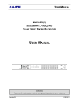
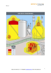
1.6 The Rear Panel
For detailed connection information, see section 1.7.
1
2
4
3
5
6
8
7
9
SVHS
RS-232-2
2
RS-232-1
1
2
3
4
5
6
7
RS-485
12V DC
8
9
10
11
12
13
14
15
16
1
B
SCSI
10
11
12
1. 10/100 Ethernet Port: For connecting to remote PC via ethernet.
2. RS-232 Port 1: For modem connection, text insertion, and flashing the PPC.
3. Power Connector: Connect 12 volt DC power supply. 2.1mm barrel connector, Center Positive.
4. Camera Inputs: BNC connector, looping. Auto Terminating.
5. RS-232 Port 2: For external control of the unit, and flashing the main software.
6. Y/C Monitor-A Output: Y/C video output with 4-pin miniDIN style connector.
0150-0138D
9
Calibur DVMRe
7. RS-485 Connector: For connecting several units to a single keyboard, or vice-versa.
8. Composite Monitor-A Output: Composite video output with BNC style connector.
9. Camera Inputs: BNC style connector, looping. Auto Terminating.
10. SCSI Port: For connecting SCSI compatible archive devices.
11. Alarm I/O: For connecting alarm inputs, and alarm output relays.
12. Monitor-B Output: Composite video output with BNC style connector.
1.7 Connections
This section contains connection specifications for the DVMRe only. For instructions regarding the
connection of the associated security equipment in your system, please consult the instruction manual
of the associated equipment.
Associated equipment in a typical security system could contain the following items:
•
A primary monitor.
•
A secondary monitor.
•
A Keyboard.
•
Video cameras: 1 volt peak-to-peak, with composite video outputs.
•
Alarm input devices: Pressure sensors, motion detectors, etc.
•
Alarm output devices: Buzzers, Sirens, Flashing Lights, Etc.
•
A PC connected via the ethernet.
•
An external archive device, such as a SCSI CD, DAT, or AIT drive.
Ethernet Port
The cable connection configuration depends on your
network configuration:
•
For a DVMRe that connects directly to a Hub,
use a Straight Through connection.
•
For a DVMRe that connects directly to a PC, use
a Cross Over connection.
Consult with you MIS personnel for the specific type
of configuration. See section 7.10 for information
about configuring the ethernet settings in the menu
system.
Wire Type: Cat 5
Connector Type: RJ-45
Max Cable Length: 100 feet / 30.5 meters
Minimum Cable Length: 6 feet / 1.8 meters
Hub Wiring Configuration: Straight Through
PC Wiring Configuration: Cross Over
RJ-45 Pin Configuration For Ethernet Port
Pin
Use
Pin
Use
1
TX+
5
Not Connected
2
TX-
6
RX-
3
RX+
7
Not Connected
4
Not Connected
8
Not Connected
Calibur DVMRe
- 10 -
1 2 3 4 5 6 7 8
RJ-45 socket on
rear panel.
0150-0138D
RS-232 Port 1
For Modem and Flash Software Upgrading, connect
a Null Modem cable. See section 7.10 for
information about configuring the modem settings in
the menu system.
Connector Type: DB-9
See the documentation of the text translating device
for cable pin-out specifications.
Cable Required (Flash): Modem
Gender (on unit): Male
Cable Required (Modem): Modem
Cable Required (Text Insertion):
Unspecified, see pin configuration for text
translator.
DB-9 Pin Configuration For Port 1
Pin
Use
Pin
Use
Pin
Use
1
DCD
4
Not Connected
7
RTS
2
RX
5
Ground
8
CTS
3
TX
6
Not Connected
9
Not Connected
5
9
1
6
DB-9 on rear panel.
Camera Inputs
There are two BNC jacks for each camera. Either
jack can receive a camera signal. The signal is
looped (directly connected to the other jack), making
the camera signal available to other equipment.
Cable: 75-Ohm Coaxial
The camera input connectors are Auto Terminating.
Make sure there is a 75-Ohm termination at the end
of the video line if the signal is looped through the
DVMRe.
Passive Looping: Yes
Connectors: BNC
Auto Terminating: Yes
Time base correction is performed during digital capture. As a result, cameras do not require
synchronization.
See section 7.8 for information about disabling unused camera jacks in the menu system.
RS-232 Port 2
Use the pin-out configuration given below to select
the proper cable.
Connector Type: DB-9
Gender (on unit): Female
DB-9 Pin Configuration For Port 2
Pin
Use
Pin
Use
Pin
Use
1
Not Connected
4
Not Connected
7
Not Connected
2
RX
5
Ground
8
Not Connected
3
TX
6
Not Connected
9
Not Connected
1
6
The DVMRe supports two types of Monitor-A outputs (Composite and Y/C). Y/C video output has a 4pin miniDIN style connector. This style of connection is also referred to as SVHS and S-Video. The
Composite video output has a BNC style connector.
11
9
DB-9 on rear panel.
Monitor-A Output
0150-0138D
5
Calibur DVMRe
Composite Monitor-A Output
When connecting directly from the DVMRe to the
monitor, select the 75-Ohm impedance setting on the
monitor.
Cable: 75-Ohm Coaxial
Connectors: BNC
If an additional device is connected to the monitor’s looping output, set the termination of the additional
device as 75-Ohm, and set the termination of the monitor as Hi-Z (High Impedance).
RS-485 Connector
Wire Type: Cat 5
Shields are grounded at one end, preferably at the
DVMRe.
Connector Type: RJ-45
See section 7.10 for information about configuring
the RS-485 network address settings in the menu
system.
Max Cable Length: 3200 feet / 1000 meters
RJ-45 Pin Configuration For RS-485 Port
Pin
Use
Pin
Use
1
Ground (Shield)
5
Not Connected
2
+12 Volt DC
6
Network -VE
3
Network +VE
7
Ground (Shield)
4
Not Connected
8
+12 Volt DC
1 2 3 4 5 6 7 8
RJ-45 socket on
rear panel.
SCSI Port
The unit is equipped with a SCSI port for
connecting external archive devices. The unit only
supports a single SCSI device. The SCSI ID must
be set to 0.
Connector: 50 Pin, High Density SCSI-2.
The SCSI bus must be terminated, otherwise the
system will not operate properly.
Autoloader Support?: Yes
Additional menu setup may be necessary to
configure archive device. See section 7.9.
Gender (on unit): Female
Compatible devices: DAT, AIT, CD-R, CD-RW
SCSI ID: 0
Monitor-B Output
When connecting directly from the DVMRe to the
monitor, select the 75-Ohm impedance setting on the
monitor.
Cable: 75-Ohm Coaxial
Connectors: BNC
If an additional device is connected to the monitor’s looping output, set the termination of the additional
device as 75-Ohm, and set the termination of the monitor as Hi-Z (High Impedance).
1.8 Alarm I/O Port
The rear panel of the unit is equipped with an Alarm
Port (DB-25 style connector).
Do not attempt to wire directly to the DB-25
connector on the rear panel.
25
13
14
1
DB-25 Connector on Rear Panel
Connect the Alarm PCB (supplied with the unit) to the Alarm Port. Wire all alarm inputs to the Alarm
PCB.
Calibur DVMRe
- 12 -
0150-0138D
If the Alarm PCB is lost or missing, contact Kalatel Customer Support for a replacement (Part Number
0900-0077B). As a substitute, purchase a female DB-25 connector and make all connections as
shown in this section.
Pin 13: Alarm Input 13.
Pin 2: Alarm Input 2.
Pin 14: Alarm Input 14.
Pin 3: Alarm Input 3.
Pin 15: Alarm Input 15.
Pin 4: Alarm Input 4.
Pin 16: Alarm Input 16.
Pin 5: Alarm Input 5.
Pin 17: Alarm Output Relay #1.
Pin 6: Alarm Input 6.
Pin 18: Ground.
Pin 7: Alarm Input 7.
Pin 19: Ground.
Pin 8: Alarm Input 8.
Pin 20: Ground.
Pin 9: Alarm Input 9.
Pin 21: Alarm Output Relay #1 Common Ground.
Pin 10: Alarm Input 10.
Pin 22: Alarm Output Relay #2.
Pin 11: Alarm Input 11.
Pin 23: External Alarm Silence and Acknowledge.
Pin 12: Alarm Input 12.
Pin 25: Alarm Output Relay #2 Common Ground.
Signal A13 COM2 A12 Vext A11 ACK A10 NO2
PIN 13
25
12
24
11
23
10
22
5
18
6
19
19
A5 GND A6 GND GND
A9 COM1 A8 GND A7
9
21
8
20
7
14
A14
17
NO1
PIN
1
Signal A1
Pin 1: Alarm Input 1.
2
A2
15
A15
3
A3
16
A16
4
A4
Alarm PCB
Alarm Input
High: 5V (12V Tolerant)
An alarm condition can be activated by devices such as pressure pads,
passive infrared detectors, door switches, or other similar devices.
Low: Ground
See section 7.5 for information about configuring the contacts as Normally
Open or Normally Closed in the menu system.
Inputs: 1 per channel.
Normally Open Zero Potential Relay Contact: Configure in menu as Normally Open.
Normally Closed Zero Potential Relay Contact: Configure in menu as Normally Closed
TTL Active High: Configure in menu as Normally Closed.
TTL Active Low: Configure in menu as Normally Open.
Open Collector Active On: Configure in menu as Normally Open.
Open Collector Active Off: Configure in menu as Normally Closed.
Multiplexer DB25 Connector
Alarm Input No. 1
Alarm Input No. 2 - 15
pin 1
Normally Open
(Closes During Alarm)
pins 2-15
Typical Alarm Device
Alarm Input No. 16
Ground
pin 16
Refer to each alarm device's manual for specific wiring details.
pins 18-20
Normally Closed
(Opens During Alarm)
Typical wiring for Alarm #1 as Normally
Open and Alarm #16 as Normally Closed.
Typical Alarm Device
Normally Open and Normally Closed Connections
0150-0138D
13
Calibur DVMRe
Alarm Relay Output
The alarm relay output is activated when an alarm condition
exists. The alarm output is only active for the duration of the
alarm.
Output: Zero potential relay contacts,
programmable in menu system as
Normally Open or Normally Closed.
Alarm relays can be programmed in the menu system to
respond to macros, and video loss. See section 7.5 for
information about configuring the alarms in the menu system.
Voltage: 30V (Max)
Current: 500mA (Max)
Typical wiring for Alarm Relays. Relays may be
programmed Normally Open or Normally Closed.
pin 17
Alarm
Device
Output Relay No. 1
Power
Source
pin 21
pin 22
Output Relay No. 2
Power
Source
Controlled
Device
pin 25
Multiplexer DB25 Connector
External Alarm Silence And Acknowledge
External Device: Normally Open
Connect a switch or similar device to Silence and
Acknowledge alarms. Connect from pin 23 to either pin 18,
Zero potential relay contact.
19, or 20 (ground pins).
Silencing and Acknowledging an alarm only deactivates the internal buzzer. The alarm output relay
will remain active for the duration of the alarm event.
1.9 Power-Up
It is important that the power-up procedures be followed carefully. The unit uses its auto-detect
feature to detect camera signals during power-up, and configure itself automatically.
Power Supply
Power Supply Input
The unit is furnished with a power supply.
Do not use any other power supply with the unit. The
manufacturer accepts no responsibility for damage
caused by the use of any other power supply.
Voltage: 120 to 240 Volt AC
Tolerance: ±10%
Frequency: 50 to 60 Hz
Power Supply Output
Voltage: 12 Volt DC
Power: 35 Watt
Connector: 2.1mm barrel, Center Positive
Calibur DVMRe
- 14 -
0150-0138D
Power-up procedure
Once the system installation is complete, apply power in the following order:
1. Energize the monitors and all of the cameras.
2. Energize the DVMRe.
Once power is applied to the unit, it will begin its power-up procedure. The unit will begin by displaying
the software version on Monitor-A, then the unit will begin recording automatically.
Duplex: Duplex units will display a multiscreen on Monitor-A.
Simplex: Simplex units will display Camera-1 full screen.
Check Video Input Quality
Check the picture quality by selecting each camera for full screen display. If the picture quality is poor,
check the following items:
•
The BNC connections.
•
The loop-through terminations.
•
The video levels of incoming signals.
•
The possibility of ground loops.
Check Record And Playback Quality
Record for at least three minutes at the highest record rate (30 pps for NTSC, 25 pps for PAL). Then
playback the recording, selecting each camera for full screen display. Check the playback picture
quality. If there is a problem with the a camera’s video quality, or for additional information about
proper camera setup, consult the camera’s installation instructions.
1.10
Minimum Recommended Menu Setup
After installation is complete, it is strongly recommended that, as a minimum, the items in the
QuickInstall menu be configured before the unit is used. All items located in the QuickInstall menu
(except Monitor Setup and ADM) are also found in the Main menu. These items are provided in the
separate QuickInstall menu as a convenience for the installer.
For information about accessing and configuring the menu system see section 6.
0150-0138D
15
Calibur DVMRe
To find detailed information in this manual about configuring each item in the QuickInstall menu, use
the following table to locate the primary menu location of each item in the QuickInstall menu.
QuickInstall Menu Item
Primary Menu Location
Section In
Manual
Change the time
Main Menu → Time/Date → Set Time
7.2
Change the date
Main Menu → Time/Date → Set Date
7.2
Edit Camera Titles
Main Menu → Camera Setup → Camera Titles
7.8
Camera Disable
Main Menu → Camera Setup → Camera Disable
7.8
Record Quality
Main Menu → Record → Record Quality
7.4
Installer Password
Main Menu → Passwords → Installer Password
7.13
Auto Disable Now
Main Menu → Camera Setup → Camera Disable
→ Auto Disable Now
7.8
Color Detect Now
Main Menu → Camera Setup → Camera Color →
Color Detect Now
7.8
Monitor Setup
QuickInstall → Monitor Setup
8.2
ADM
QuickInstall → ADM
8.3
Calibur DVMRe
- 16 -
0150-0138D
2
User Operations
2.1 Principal Operating Modes
The DVMRe has four principal modes of operation:
•
•
Recording.
• Playback.
•
Each mode is discussed in detail later in this section.
Live Multiscreen.
Stop.
2.2 Simplex Vs. Duplex
Simplex: The unit is only capable of operating in a single mode. For Example, selecting Live
Multiscreen cancels the Recording operations.
Duplex: The unit is capable of performing the following tasks concurrently:
•
Viewing Live Multiscreen images while Recording.
•
Viewing Live Multiscreen images during Playback.
There are notes throughout this manual describing the difference in operation of specific features
between simplex and duplex.
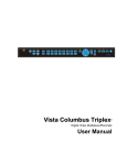
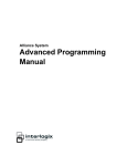
2.3 The Front Panel
1
2
3
4
5
6
1
2
3
4
5
6
7
8
9
10
11
12
13
14
15
16
{F}
B
7
8
9
10 11 12 13 14 15
16
17
1. Multiscreen button.
7. Monitor-B button.
13. Function button.
2. Live button.
8. Record button.
14. Freeze button.
3. Play button.
9. Reverse Play button.
15. Search button.
4. Play Forward button.
10. Alarm button.
16. Number buttons.
5. Stop button.
11. Sequence button.
17. Arrow button.
6. Menu button.
12. Zoom button.
18. Enter button.
18
2.4 Recording
To begin recording, press the Record button. Recording will be indicated by the
LED located directly above the Record button. Recording is also indicated as
REC on the primary monitor. The unit always starts recording at the end of
previously recorded data.
The unit will continue recording until:
•
The disk is full.
•
The Play button or Stop button is pressed.
Record Button
with LED
On Simplex units, recording is also stopped when the Multiscreen button is pressed.
0150-0138D
- 17 -
Calibur DVMRe
Disk Nearly Full Notification
When the recorder has less than 10% of its disk space available, the unit will begin toggling between
the Multiscreen and Full screen, displaying (on the Full screen display) an on-screen notification
indicating that the disk is nearly full.
The operator has the option to let the unit stop recording when
the disk is full, or command the unit to continue recording when
the disk becomes full, by recording over the oldest recorded
information.
On the Full screen display, this pop-up menu will appear.
Pressing the record button now will continue recording and begin
overwriting data.
MESSAGE
Recording will stop
when disk is full.
Press RECORD to
continue.
The percentage of space remaining on the hard disk and the amount of time until recording is stopped
is indicated on both Full screen and Multiscreen displays.
If the operator allows the disk to become full, this dialog box will appear.
Press the Enter button to clear the dialog box and return the unit to
Stop mode. The unit will not continue recording again until the operator
pushes the Record button.
MESSAGE
Recording stopped.
Disk Full.
Monitor-A Displays During Recording
Multiscreen Display
During Recording, press the Multiscreen button to activate the multiscreen
display on Monitor-A. Repeatedly pressing the Multiscreen button
advances the display to the next multiscreen. For detailed information
about Multiscreen displays, see section 3.1.
Multiscreen Button
Multiscreen Display with Sequencing
If a multiscreen display does not include all of the cameras, the remaining
cameras can be sequenced in the bottom right cameo. While in a multiscreen
display, press the Sequence button to begin sequencing. For detailed
information about sequencing, see section 3.3.
Sequence Button
Full Screen Display
Select any camera for Full Screen display by pressing the Number button of
the desired camera.
1
Number Button
Sequenced Full Screen Display
While in a Full Screen display, press the Sequence button to begin full
screen sequencing. The sequence list and dwell times are programmable.
For detailed information about programming the sequence list see section
3.3. For detailed information about configuring the dwell times in the menu
system, see section 7.3.
Sequence Button
Calibur DVMRe
- 18 -
0150-0138D
Zooming
To activate the 2x digital zoom, select the full screen display of the camera
you wish to zoom, then press the Zoom button. Zooming will be indicated by
the LED located directly above the Zoom button. Zooming is also indicated
as ZOOM on the primary monitor. Zooming works with frozen and non-frozen
images. Zoomed images can also be frozen.
While Zoomed, use the Arrow buttons to Pan and Tilt across the image.
Please note, the camera does not move during digital Pan/Tilt.
Press the Zoom button again to cancel the Zoom operations.
Zoom Button
with LED
If the Zoom button is pressed while in a multiscreen display, the camera from the last active cameo is
selected for full screen display. Press the Zoom button again to activate the Zoom operation.
Freezing
Pressing the Freeze button freezes all camera images on-screen. Full
Screen freezing is indicated as FRZ on-screen. Multiscreen freezing is
indicated as * (a flashing asterisk) in each frozen cameo.
Individual cameos can be frozen in Active Cameo mode (see section 3.2).
Press the Freeze button again to cancel Freeze operations.
Freeze Button
Monitor-B Displays During Recording
During recording, Monitor-B displays a single camera, live and full screen. These images cannot be
zoomed or frozen.
Selecting Monitor-B
To change cameras on Monitor-B, press the Monitor-B button. The MonitorB LED will light to indicate that the number buttons now control Monitor-B.
Press the Monitor-B button again to return the keypad control to Monitor-A.
B
Monitor-B Button
Full Screen Display
Select any camera for Full Screen display on Monitor-B by pressing the
Number button of the desired camera.
1
Number Button
Sequenced Display
Press the Sequence button to begin sequencing. The sequence list and
dwell times are programmable. For detailed information about programming
the sequence list see section 3.3. For detailed information about configuring
the dwell times in the menu system, see section 7.3.
Sequence Button
0150-0138D
19
Calibur DVMRe
2.5 Playback
Start Playback
To begin playback, press the Play button. A message will appear prompting “Do
you want to stop Record?”.
To stop recording and continue with playback: Press the Enter button.
Recording will stop, Playback will start. Playback starts at the beginning of the
last recording session. Playback will be indicated by the LED located next to the
on the playback monitor.
Play button. Playback is also indicated as
Play Button
with LED
To cancel selection and continue recording: Press the Menu button or wait a few seconds for the
message to disappear.
Playback Operations
Play Forward
When playback begins, the default is to play forward at the rate the data was
recorded. While in Playback mode, the user may change the playback direction,
playback speed, etc. To return to Play Forward operations, press the Play
on the playback monitor.
Forward button. Play Forward is indicated as
Play Forward
Button
Reverse Play
To begin reverse playback, press the Reverse Play button. Reverse Play is
indicated as on the playback monitor.
Reverse Play
Button
Fast Forward
During playback, press the Right Arrow button. The unit will display images at a
on the playback
higher than normal rate. Fast Forward is indicated as
monitor. There are 4 Fast Forward rates. Repeated pressing of the Right Arrow
button will increase the playback speed.
Right Arrow
Button
Rewind
During playback, press the Left Arrow button. The unit will display images (in
on the playback
reverse) at a higher than normal rate. Rewind is indicated as
monitor. There are 4 Rewind rates. Repeated pressing of the Left Arrow button
will increase the rewind speed.
Left Arrow
Button
Skip Forward
During playback, press the Up Arrow button. The unit will skip forward through
approximately 120 megs of data on the hard disk. After skipping, the unit will
return to the previous playback mode (Play Forward, Reverse Play, Fast Forward,
Rewind, etc.). Skip Forward is indicated as
on the playback monitor.
Up Arrow
Button
Calibur DVMRe
- 20 -
0150-0138D
Skip Rewind
During playback, press the Down Arrow button. The unit will skip back through
approximately 120 megs of data on the hard disk. After skipping, the unit will
return to the previous playback mode (Play Forward, Reverse Play, Fast Forward,
on the playback monitor.
Rewind). Skip Rewind is indicated as
Down Arrow
Button
Pause
During playback, press the Freeze button. The is feature pauses all full screen
and multiscreen images. Pause is indicated as on the playback monitor.
Freeze Button
Single Frame Advance
While in Pause mode, press the Play Forward button. The unit will advance a
single frame, then return to Pause mode. Single Frame Advance is indicated as
on the playback monitor.
Play Forward
Button
Single Frame Rewind
While in Pause mode, press the Reverse Play button. The unit will rewind a
single frame, then return to Pause mode. Single Frame Rewind is indicated as
on the playback monitor.
Reverse Play
Button
Stop Playback
To stop playback and return to Live Multiscreen mode, press
either the Stop button or the Live button.
Pressing the Record button will stop playback, and return the unit
to Record mode.
Stop Button or Live Button
Searching Recorded Data
The DVMRe has a search interface feature that allows the user to search for data on the internal hard
disk or an external archive device. The user may search the data for previous recording sessions, text
insertion, or alarm conditions. Because the search interface is so dynamic, it is covered in detail in a
separate section of this manual. See section 5.
Single Monitor Mode Vs. Dual Monitor Mode
The Monitor mode determines which monitor will display the video playback. This feature is
configured in the QuickInstall menu. This feature is only available on Duplex units.
Single Monitor Mode
Monitor-A: Full Screen or Multiscreen Video Playback is displayed.
Monitor-B: Live Full Screen images are displayed.
Video playback replaces the live video on Monitor-A.
0150-0138D
21
Monitor-A
Monitor-B
Calibur DVMRe
Dual Monitor Mode
Monitor-A: Live Full Screen or Multiscreen images are displayed.
Monitor-B: Full Screen or Multiscreen Video Playback is displayed.
Monitor-A
Monitor-B
The primary function of Dual Monitor mode is to provide multiscreen
playback on Monitor-B, while continuing to display live multiscreen video
on Monitor-A. Dual Monitor mode requires two monitors.
Playback in Dual Monitor mode is the only time a multiscreen will be displayed on Monitor-B.
Playback Monitor Displays
The following information is about the playback monitor. Depending on how the unit is configured, this
may be Monitor-A or Monitor-B.
Multiscreen Display
During Playback, press the Multiscreen button to activate the multiscreen
display. Repeatedly pressing the Multiscreen button advances the display
to the next multiscreen. For detailed information about Multiscreen
displays, see section 3.1.
Multiscreen Button
Multiscreen Display With Sequencing
If a multiscreen display does not include all of the cameras, the remaining
cameras can be sequenced in the bottom right cameo. While in a multiscreen
display, press the Sequence button to begin sequencing. For detailed
information about sequencing, see section 3.3.
Sequence Button
Full Screen Display
Select any camera for Full Screen display by pressing the Number button of
the desired camera.
1
Number Button
Sequenced Full Screen Display
While in a Full Screen display, press the Sequence button to begin full
screen sequencing. The sequence list and dwell times are programmable.
For detailed information about programming the sequence list see section
3.3. For detailed information about configuring the dwell times in the menu
system, see section 7.3.
Sequence Button
Zooming
To activate the 2x digital zoom, select the full screen display of the camera
you wish to zoom, then press the Zoom button. Zooming will be indicated by
the LED located directly above the Zoom button. Zooming is also indicated
as ZOOM on the monitor. Zooming works with frozen and non-frozen
images. Zoomed images can also be frozen.
While Zoomed, use the Arrow buttons to Pan and Tilt across the image.
Please note, the camera does not move during digital Pan/Tilt.
Press the Zoom button again to cancel the Zoom operations.
Zoom Button
with LED
If the Zoom button is pressed while in a multiscreen display, the camera from the last active cameo is
selected for full screen display. Press the Zoom button again to activate the Zoom operation.
Calibur DVMRe
- 22 -
0150-0138D
Freezing
Pressing the Freeze button freezes all camera images on-screen. Full
Screen freezing is indicated as FRZ on-screen. Multiscreen freezing is
indicated as * (a flashing asterisk) in each frozen cameo.
Individual cameos can be frozen in Active Cameo mode (see section 3.2).
Press the Freeze button again to cancel Freeze operations.
Freeze Button
Monitor-A Displays During Playback (Dual Monitor mode)
Same as above, except images are live.
Monitor-B Displays During Playback (Single Monitor Mode)
During playback, Monitor-B displays a single camera, live and full screen. These images cannot be
zoomed or frozen.
Selecting Monitor-B
To change cameras on Monitor-B, press the Monitor-B button. The MonitorB LED will light to indicate that the number keypad now controls Monitor-B.
Press the Monitor-B button again to return the keypad control to Monitor-A.
B
Monitor-B Button
Full Screen Display
Select any camera for Full Screen display on Monitor-B by pressing the
Number button of the desired camera.
1
Number Button
Sequenced Display
Press the Sequence button to begin sequencing. The sequence list and
dwell times are programmable. For detailed information about programming
the sequence list see section 3.3. For detailed information about configuring
the dwell times, see section 7.3.
Sequence Button
2.6 Live Multiscreen Mode
To enter Live Multiscreen mode, press the Live button. Live Multiscreen
mode will be indicated by the LED located next to the Live button.
Simplex Units: Entering the Live Multiscreen mode stops all playback and
recording.
Duplex Units: Entering the Live Multiscreen mode stops playback. The unit
will continue recording while the live multiscreen video is displayed.
Live Button
Monitor-A Displays In Live Multiscreen Mode
Multiscreen Display
In Live Multiscreen mode, press the Multiscreen button to activate the
multiscreen display on Monitor-A. Repeatedly pressing the Multiscreen
button advances the display to the next multiscreen. For detailed
information about Multiscreen displays, see section 3.1.
0150-0138D
23
Multiscreen Button
Calibur DVMRe
Multiscreen Display With Sequencing
If a multiscreen display does not include all of the cameras, the remaining
cameras can be sequenced in the bottom right cameo. While in a multiscreen
display, press the Sequence button to begin sequencing. For detailed
information about sequencing, see section 3.3.
Sequence Button
Full Screen Display
Select any camera for Full Screen display by pressing the Number button of
the desired camera.
1
Number Button
Sequenced Full Screen Display
While in a Full Screen display, press the Sequence button to begin full
screen sequencing. The sequence list and dwell times are programmable.
For detailed information about programming the sequence list see section
3.3. For detailed information about configuring the dwell times in the menu
system, see section 7.3.
Sequence Button
Zooming
To activate the 2x digital zoom, select the full screen display of the camera
you wish to zoom, then press the Zoom button. Zooming will be indicated by
the LED located directly above the Zoom button. Zooming is also indicated
as ZOOM on the primary monitor. Zooming works with frozen and non-frozen
images. Zoomed images can also be frozen.
While Zoomed, use the Arrow buttons to Pan and Tilt across the image.
Please note, the camera does not move during digital Pan/Tilt.
Press the Zoom button again to cancel the Zoom operations.
Zoom Button
with LED
If the Zoom button is pressed while in a multiscreen display, the camera from the last active cameo is
selected for full screen display. Press the Zoom button again to activate the Zoom operation.
Freezing
Pressing the Freeze button freezes all camera images on-screen. Full
Screen freezing is indicated as FRZ on-screen. Multiscreen freezing is
indicated as * (a flashing asterisk) in each frozen cameo.
Individual cameos can be frozen in Active Cameo mode (see section 3.2).
Press the Freeze button again to cancel Freeze operations.
Freeze Button
Monitor-B Displays In Live Multiscreen Mode
In Live Multiscreen mode, Monitor-B displays a single camera, live and full screen. These images
cannot be zoomed or frozen.
Selecting Monitor-B
To change cameras on Monitor-B, press the Monitor-B button. The MonitorB LED will light to indicate that the number keypad now controls Monitor-B.
Press the Monitor-B button again to return the keypad control to Monitor-A.
B
Monitor-B Button
Calibur DVMRe
- 24 -
0150-0138D
Full Screen Display
Select any camera for Full Screen display on Monitor-B by pressing the
Number button of the desired camera.
1
Number Button
Sequenced Display
Press the Sequence button to begin sequencing. The sequence list and
dwell times are programmable. For detailed information about programming
the sequence list see section 3.3. For detailed information about configuring
the dwell times in the menu system, see section 7.3.
Sequence Button
2.7 Running A Macro
A macro is a recorded sequence of up to 32 keystrokes. To activate a
macro, press the Function button followed by the Number button of the
desired macro. While running, the macro is indicated on-screen as the letter
F and the macro number.
The user can cancel the macro at any time by pressing the Function button.
{F}
1
Function and
Number Buttons
Daylight Savings Time
To adjust the time one hour for daylight savings time, press the Function
button, then the Sequence button. If this function is activated during April,
one hour is added to the time. If the this function is activated in October,
one hour is subtracted from the time. This function will only operate once
per time period.
{F}
Function and
Sequence Buttons
0150-0138D
25
Calibur DVMRe
Calibur DVMRe
- 26 -
0150-0138D
3
Display Options
3.1 Available Multiscreen Displays
Press the Multiscreen button to activate the multiscreen display. Repeatedly pressing the Multiscreen
button advances the display to the next multiscreen, show in order below.
16-Way
13-Way
10-Way
9-Way
7-Way
4-Way
The multiscreen display is limited to the number of camera inputs on the unit.
Sixteen-Channel unit: Capable of displaying all multiscreens.
Ten-Channel unit: Only capable of displaying 10-way through 4-way multiscreen.
Four-Channel unit: Only capable of displaying 4-way multiscreen.
Multiscreen Format Memory
When returning to a multiscreen display from a full screen display, the unit returns to the last
multiscreen display shown.
3.2 Active Cameos
A cameo is defined as any cell within a multiscreen display. Active Cameo mode allows the user to
access and edit each cameo individually.
Entering Active Cameo Mode
While viewing a multiscreen, enter Active Cameo mode by pressing the Enter
button. Active Cameo mode is indicated on-screen by flashing the number
and titles of the active cameo. By default, the top left cameo is activated.
Enter Button
Selecting Cameos
Select a cameo using the Arrow buttons to navigate the multiscreen. The
Active Cameo will always be indicated by the flashing camera number and
titles.
Arrow Buttons
Selecting Cameras
Display any camera in the active cameo by pressing the Number button of
the desired camera. Once a camera has been selected, the active cameo
advances to the next cameo on the right.
1
Number Button
The camera selection only changes the multiscreen currently being displayed. Each multiscreen must
be configured separately. Changes to the multiscreen display are saved in volatile memory, and will
not be retained if power is removed from the unit.
0150-0138D
- 27 -
Calibur DVMRe
Freezing
Press the Freeze button to freeze the image in the selected cameo. Each
frozen cameo is indicated as * (a flashing asterisk) on-screen.
Press the Freeze button again to cancel Freeze operations.
Freeze Button
3.3 Sequencing
The sequencing feature allows a camera to be displayed briefly on-screen, before advancing to the
next camera in the sequence list. The default sequence list displays each camera in numerical order.
Dwell Time
The dwell time is the amount of time each camera is displayed on-screen before advancing to the next
camera. The Full Screen and Multiscreen Dwell Times are separately programmable in the menu
system. For detailed information about configuring the dwell times in the menu system, see section
7.3.
Autolist™ Custom Sequence List
The Autolist™ feature allows the user to create a custom sequence list, controlling the order the
cameras are displayed and the dwell time. Using the Monitor-B button, select the monitor to be
programmed. Then, using a Number button, select any camera for full screen display.
The unit must be in Full Screen Display mode before starting to create the sequence list. This initial
camera is not part the sequence list.
To begin recording the Autolist™ sequence: Press the Alarm button and
Sequence button simultaneously. Autolist Program mode is indicated as
PGM on-screen.
Recording starts when the first camera number is pressed. Press the camera
numbers in the order you wish them to appear on-screen. The amount of
time between button presses determines the Dwell Time. During sequence
list recording, pressing any button other than a Number button or the
Sequence button voids the sequence list.
Alarm Button and
Sequence Button
To end the recording: Press the Sequence button. The amount of time between pressing the last
Number button and the Sequence button determines the dwell time for the final camera in the
sequence list.
Returning To The Default Sequence List
The default sequence list is all cameras in numeric order with a three second dwell time.
To return the unit to the default sequence list, go to the Main Menu → Sequencing → Full Screen
Dwell menu. Select 03 seconds using the Up/Down Arrow buttons, then press the Enter button.
Note: Any alteration of the dwell time from this menu will cancel the sequence list and return to the
default (numeric) order.
Sequencing In Cameos
While viewing a multiscreen display, additional cameras (cameras not shown in the multiscreen
display) can be sequenced in the lower right hand cameo by pressing the Sequence button. The
sequence list is not programmable, but the dwell time can be adjusted in the menu system. Press the
Sequence button again to cancel sequencing.
Calibur DVMRe
- 28 -
0150-0138D
3.4 On-screen Indicators
Monitor-A
There are three groups of on-screen indicators on Monitor-A.
Camera Titles: Displays the camera number and the camera title.
Status Indicators: Displays Time, Date, Mode, Hard Disk Status.
Conditional Indicators: Displays indicators for Freeze, Zoom, Alarm, Motion Detection, Videoloss,
Autolist™ Program mode, Macro Record mode.
Camera Titles
Camera Titles are displayed on either the upper or lower corner of the left hand side of the screen.
The camera title can be changed in the menu system (see section 7.8). Display position and color can
be changed by the user. See below.
Status Indicators
Typically, status indicators are displayed on the upper right hand corner
of the screen. On the 16-way and 13-way multiscreens, the Mode and
Hard Disk Status are displayed near the upper left hand corner of the
screen so that it does not obscure the small cameo in the corner of the
screen.
13-Way
16-Way
Small Cameo
Status indicators include:
•
Time and Date (these can be turned off in the menu system, see section 7.2). The Time and Date
format can also be changed in the menu system.
•
Mode (Record or Playback).
•
Disk Status (Percent of hard disk available and hours of recording until disk becomes full).
•
Archive Status (Toggles with Disk Status when archive device is almost full. Displays percent of
archive space available and hours of recording until archive device becomes full).
Changing Position And Color Of Title And Status Indicators
Camera Titles: To change the color and position of the camera
titles, select a camera for full screen display, then press the Enter
button to advance to the next display setting. Repeatedly pressing
the Enter button advances the display settings through the
sequence show in the table on the right.
Status Indicators & Camera Titles: Select Camera 1 for full
screen display. Using the Enter button, cycle through the
sequence show on the right. Each time the cycle is completed,
the unit advances the Status Indicator color. Choose either Black,
White or Gray.
Position
Color
Top Left
Black
Top Left
White
Top Left
Gray
Bottom Left
Black
Bottom Left
White
Bottom Left
Gray
Title not displayed
0150-0138D
29
Calibur DVMRe
Conditional Indicators
Condition
Full Screen Indicator
Multiscreen Indicator
Monitor
Alarm
ALM
A in cameo of camera in alarm
Both
Autolist™ Program
mode
PGM
PGM
A
Freeze
FRZ
* (Asterisk) in frozen cameo
A
Macro Record mode
F followed by macro number
F followed by macro number
A
Motion Detection
M
M in cameo w/ motion detection
Both
Videoloss
VDL
V in cameo with videoloss
Both
Zoom
ZOOM
ZOOM
A
Monitor-B
Monitor-B displays the Time, Date, Camera Number and Camera Title. These displays can be turned
off in the menu system (see section 7.2 for Time and Date, section 7.8 for Camera Titles Display).
Calibur DVMRe
- 30 -
0150-0138D
4
Alarms
4.1 Alarm Input
Alarm devices are connected via the Alarm PCB on the rear panel of the unit (see section 1.8). Each
Alarm Input corresponds with the Camera Input of the same number.
4.2 Alarm Output
Front Panel Alarm LED: The LED located directly above the Alarm button is lit for the duration of the
alarm.
Internal Buzzer: The internal buzzer is activated until it is Silenced and Acknowledged. This feature
can be turned off in the menu system (see Buzzer Setup in section 7.5).
Monitor Displays: Discussed below in the On-screen Displays During Alarms section.
Output Relays: The alarm output relays are active for the duration of the alarm. This feature is
configured in the menu system (see Alarm Action and Relay Configuration in section 7.5) and can be
deactivated.
Macro Activation: Unit can be configured in the menu system to activate a macro when an alarm is
detected.
Record Rate: Record Rate can be increased by recording at the Alarm Record Rate (see section 7.4)
and by Interleaved or Exclusive Recording (see Alarm Record mode in section 7.5).
4.3 Silence And Acknowledge
Pressing the Alarm button acknowledges to the unit that the alarm has been recognized and silences
the internal buzzer. This does not clear the alarm condition.
4.4 On-screen Displays During Alarms
10 and 16-Channel Units (Live or Recording)
Monitor-A Duplex / Monitor-A Simplex in Live Multiscreen Mode
Single Alarm: When a single alarm is received, the unit changes to 4-way
display containing the camera in alarm, and three associated cameras. The three
associated cameras are defined as a group in the menu system (see Alarm
Action in section 7.5). The top left cameo displays the camera in alarm.
4-Way
Single Alarm
Second Alarm: When a second alarm is received, the unit changes to a 10-way
multiscreen, displaying the alarm cameras in the top two cameos. The
associated cameras are displayed in the remaining cameos.
10-Way
Second Alarm
Third Alarm: When a third alarm is received, the unit changes to a 9-way
multiscreen, displaying the alarm cameras in the top three cameos. The
associated cameras are displayed in the remaining cameos.
More than three alarms simultaneously: The unit switches to a sequenced full
screen display of all cameras in alarm.
0150-0138D
- 31 -
9-Way
Third Alarm
Calibur DVMRe
Other display options include:
•
A full screen display of a single camera in alarm, with a sequenced full screen display for
additional cameras in alarm. This option is selectable in the menu system (see Full Screen Alarm
in section 7.5).
•
Freeze camera display at the time the alarm was received.
Monitor-A Simplex in Record Mode
Single Alarm: Unit switches to a full screen display of the camera in alarm.
Additional Alarms: Unit switches to a sequenced display of all cameras in alarm.
Monitor-B Display During Alarm
Single Alarm: Unit switches to a full screen display of the camera in alarm.
Additional Alarms: Unit switches to a sequenced display of all cameras in alarm.
4-Channel Units (Live or Recording)
Single Alarm: Unit switches to a full screen display of the camera in alarm.
Additional Alarms: Unit switches to a sequenced display of all cameras in alarm.
4.5 Alarm Operations During Playback
Live Alarms Displays
Single Alarm: Unit switches to a full screen display of the camera in alarm.
Additional Alarms: Unit switches to a sequenced display of all cameras in alarm.
Duplex Units in Dual Monitor Mode: Live alarms are displayed on Monitor-A, and operate the same
as Monitor-A Duplex (above).
Recorded Alarms
Internal Buzzer: During playback, the internal buzzer is activated until it is Silenced and
Acknowledged. This feature can be turned off in the menu system (see Buzzer Setup in section 7.5).
Front Panel Alarm LED: The LED located directly above the Alarm button is lit for the duration of the
alarm.
Monitor-A Multiscreen: Each camera in alarm is indicated on-screen by a flashing A in its cameo.
Alarm LED lights to indicate an alarm condition.
Monitor-A Full Screen: The alarm condition is indicated as ALM on-screen.
4.6 Alarm History Box
The Alarm History feature provides a list of the 100 most recent alarms. View the Alarm History Box
by accessing the menu system, and selecting Operator → Alarm History. The Alarm History Box
can also be found under Main Menu → Alarm → Alarm History. For detailed information about
viewing the Alarm History Box see Alarm History in section 7.5.
4.7 Searching For Recorded Alarms
Use the Search Filters Menu to create a list of recorded alarms by searching the previously recorded
video data for alarms, then select from the list to view the recorded video. Because the search
interface is so dynamic, it is covered in detail in a separate section of this manual. See section 5,
Searching and Archiving.
Calibur DVMRe
- 32 -
0150-0138D
5
Searching and Archiving
The unit provides a search feature to access video files stored on the hard disk or an external archive
device.
5.1 Defining Search Type
Before searching, the user must define how the results of the search will be used.
Search hard disk for video to review: From Main Menu → Video Archive Setup → Archive
Mode, select either Archiving Off or Background Archive (depending on archive requirements).
The heading of the search window will read Search Filters.
Search hard disk for video to archive: From Main Menu → Video Archive Setup → Archive
Mode, select Selective Archive. The heading of the search window will read Archive Search
Filters.
Search archive device for video to restore: From Main Menu → Video Archive Setup → Archive
Mode, select Restore From Archive. The heading of the search window will read Restore Search
Filters.
Information about setting up archiving in the menu system is covered in section 7.9 of this manual.
For detailed information about archiving, see the Archiving Addendum included with this product.
5.2 Defining Search Criteria
Begin by pressing the Search button. The Search Filters window will appear.
The unit must stop recording to enter the Search Filters window. If recording, the
user will be prompted to continue.
Search Button
Use the Search Filters menu to specify:
•
The Start and Stop date of the search.
•
The Start and Stop time of the search.
•
Which cameras to search exclusively.
•
Searching for recorded alarms.
•
Searching for a text string.
Search Filters
Start
DATE : 12/25/00
(MM/DD/YY)
Start
TIME : 11:11:21
[ ]
[ ]
Stop
03/05/01
[ ]
(MM/DD/YY)
Stop
12:34:34
[ ]
1
2
3
4
5
6
7
8
Camera: [ ] [ ] [ ] [ ] [ ] [ ] [ ] [ ]
Alarm : [ ]
TEXT : *
[ ]
[CANCEL]
[OK]
[START SEARCH]
Search Filters Menu
Searching For All Recorded Information
Using the Play Forward or Play Reverse buttons to navigate, select [Start Search], then press the
Enter button. The Search Results window will appear. For information about selecting from the
Search Results window, see Search Results later in this section.
0150-0138D
- 33 -
Calibur DVMRe
Specifying Search Parameters
Selecting A Start And Stop Date
1. Using the Play Forward or Play Reverse button to navigate, highlight the Date parameter.
2. Once in the Date Parameter Box, use the Left/Right Arrow buttons to navigate and the Up/Down
Arrow buttons to change the values.
3. To activate the start or stop date parameter, use the Up/Down Arrow buttons to place an [X] in
the check box.
4. When finished, use the Play Forward or Play Reverse button to navigate to another parameter.
Selecting A Start And Stop Time
1. Using the Play Forward or Play Reverse button to navigate, highlight the Time parameter.
2. Once in the Time Parameter Box, use the Left/Right Arrow buttons to navigate and the Up/Down
Arrow buttons to change the values.
3. To activate the start or stop time parameter, use the Up/Down Arrow buttons to place an [X] in
the check box.
4. When finished, use the Play Forward or Play Reverse button to navigate to another parameter.
Selecting Cameras To Search Exclusively
By activating this feature, the unit will only search for those cameras that are selected.
1. Using the Play Forward or Play Reverse button to navigate, highlight the Camera parameter.
2. Once in the Camera Parameter Box, use the Left/Right Arrow buttons to navigate among the
cameras in the list. To view the list for camera numbers 9 through 16, press the Right Arrow
button until the highlighted camera goes past number 8. Camera numbers 9 through 16 will
replace 1 through 8 in the list.
3. Use the Up/Down Arrow buttons to select a camera (or cameras) by placing an [X] in the check
box.
4. When finished, use the Play Forward or Play Reverse button to navigate to another parameter.
Searching For Recorded Alarms
By activating this feature, the unit will only search for recorded alarms.
1. Using the Play Forward or Play Reverse button to navigate, highlight the Camera parameter.
2. Once in the Camera Parameter Box, use the Left Arrow button to highlight the Alarm parameter.
3. Use the Up/Down Arrow buttons to activate the alarm search by placing an [X] in the check box.
4. When finished, use the Play Forward or Play Reverse button to navigate to another parameter.
Searching For Text
Use this feature to search for text generated by ATMs, Point of Sale Systems, Card Access Systems,
etc.
1. Using the Play Forward or Play Reverse button to navigate, highlight the Text parameter.
2. Once in the Text Parameter Box, press the Enter button to display the default character set.
3. Use the Function button to browse forward through the available characters sets. Use the
Sequence button to browse backwards through the available characters sets.
4. Use the Up/Down Arrow buttons to navigate in the desired character in the set.
Calibur DVMRe
- 34 -
0150-0138D
5. Use the Left/Right Arrow buttons to select the desired character and move to the next (or
previous) character in the text string. Pressing the Number 2 button will also select the desired
character and move to the next character in the text string. Pressing the Number 1 button will
insert a space.
6. When finished editing the text string, press the Enter button.
7. Use the Left/Right Arrow buttons to navigate. Use the Up/Down Arrow buttons to activate the
text search by placing an [X] in the check box.
8. When finished, use the Play Forward or Play Reverse button to navigate to another parameter.
5.3 Search Results
Activate Search
From the Search Filters menu, use the Play Forward or Play Reverse button to navigate to the Start
Search parameter. With the Start Search parameter highlighted, press the Enter button to begin the
search operation. When finished searching, the Search Results window will appear.
A maximum of 200 results
can be displayed per
search.
Follow the directions onscreen to select, archive,
playback, etc.
Some options may be
unavailable depending on
the type of search
performed. These option
are shown “grayed out”.
When archiving, the unit will
not allow the amount of
selected data to exceed the
amount of space available
on the target medium.
Archive Search Results
Start Date
03/02/01
03/05/01
03/06/01
Start Time
16:59:15
16:02:06
11:16:34
Size (MB)
11460
798
54
Archive
[X]
[X]
[X]
Selected [
Available on Target Medium [
](MB)
](MB)
Message
3 matches found
‘ENTER’ to play event; ‘PLAY REV/FWD’ to page up/down
‘LEFT/RIGHT’ to select/deselect Archive
‘PAUSE’ to select/deselect all items in this page
‘RECORD’ to start archive
Search Results Window
Press the Menu button to exit the Search Results window without making a selection.
0150-0138D
35
Calibur DVMRe
Calibur DVMRe
- 36 -
0150-0138D
6
Menu System Overview
6.1 Menu Notation In This Manual
In the following sections, there are headings like this:
Main Menu → Time/Date → Set Time
Meaning: From the Main Menu, select Time/Date, then press the Enter button. The Time/Date menu
will appear. From the Time/Date menu, select Set Time, then press the Enter button. A pop-up or
pull-down menu will appear.
Selected Items
Items selected in the menu system are represented in the manual as follows:
Selected
Not Selected
Time/Date
Time/Date
6.2 Accessing The Menu System
Enter the menu system by pressing the Menu button. A Password Box will appear
on the primary monitor. Enter either the:
•
Operator Password: Providing limited access to the menu system. Only the
Operator and System View menus are available.
•
Installer Password: Providing complete menu access.
Menu Button
Use the Number buttons or the Freeze button to enter the appropriate password.
Passwords are provided in the beginning of this manual, in section 1.3 Passwords.
6.3 Available Menus
Main
QuickInstall
Operator
SystemView
Time/Date
Change the time
Sequencing
About MUX
Sequencing
Change the date
Time/Date Display
View Screen 1
Record
Edit Camera Titles
Titles Display
View Screen 2
Alarms
Camera Disable
Alarm History
View Screen 3
View Screen 4
View Screen 5
Record Quality
Operator Password
Motion Detection
Installer Password
Exit
Camera Setup
Auto Disable Now
View Screen 6
Video Archive Setup
Color Detect Now
View Screen 7
Communications
Monitor Setup
Front Panel Lock
ADM
Factory Settings
Exit
Macro
Duplex Models Only
Exit
Passwords
Exit
0150-0138D
- 37 -
Calibur DVMRe
6.4 Menus In This Manual
Each menu is covered in detail in its own chapter of this manual. Menus and Menu Items appear in
the manual in the same order they appear on-screen.
•
Section 7 Main Menu
•
Section 8 QuickInstall Menu
•
Section 9 Operator and SystemView Menus
6.5 Navigating The Menu System
Selecting a Menu from the Menu Bar: When the menu system is first accessed, only the menu bar
is displayed. Use the Left/Right Arrow buttons to select the desired menu.
Opening Menus: Press the Down Arrow button or the Enter button to open the menus.
Exiting Menus: Press the Menu button to exit a menu. From the menu bar, press the Menu button
to exit the menu system completely.
Navigating in Menus: Use the Up/Down Arrow buttons to navigate within a menu.
Calibur DVMRe
- 38 -
0150-0138D
7
The Main Menu
7.1 Main Menu Overview
The Main menu contains the majority of programmable options for the
DVMRe. Each item in the Main menu is described in detail in this section
of the manual.
Time/Date
Sequencing
Record
Main menu items are appear in this section in the same order they
appear in the menu.
Alarms
Macro
Motion Detection
Camera Setup
Video Archive Setup
Communications
Front Panel Lock
Factory Settings
Passwords
Exit
7.2 Time/Date
Use this menu to specify:
•
Which monitors will display the time and date.
•
The time format: 12 or 24 hours.
•
The date format: MM/DD/YY, YY/MM/DD, or DD/MM/YY.
Time / Date Display
Set Time Format
Set Date Format
Set Time
Set Date
Set Master / Slave
•
The time and date.
Exit
•
Whether the units clock is a master or slave.
Main Menu → Time/Date → Time / Date Display
Use this menu to specify if the time and date will be displayed on:
Time and Date Display
•
Monitor-A.
Monitor A : ON
•
Monitor-B.
Monitor B : ON
•
Both Monitors.
[CANCEL]
•
Not Displayed
[OK]
Use the Up/Down Arrow buttons to navigate, then use the Left/Right Arrow buttons to change the
values.
Save changes and exit the menu: Select [OK], then press the Enter button.
Exit the menu without making changes: Press the Menu button, or select [CANCEL], then press
the Enter button.
0150-0138D
- 39 -
Calibur DVMRe
Main Menu → Time/Date → Set Time Format
Use the Arrow buttons to set the desired time format. Select from
either:
•
12 Hour
•
24 Hour
Time Format Setup
Select Format
12 HOUR
Press the Enter button to confirm the selection and exit the menu.
Press the Menu button to exit the menu without making changes.
Main Menu → Time/Date → Set Date Format
Use the Arrow buttons to set the desired date format. Select from
either:
•
MM/DD/YY
•
DD/MM/YY
•
YY/MM/DD
Date Format Setup
Select Format
MM/DD/YY
Press the Enter button to confirm the selection and exit the menu.
Press the Menu button to exit the menu without making changes.
Main Menu → Time/Date → Set Time
1. Using the Up/Down Arrow buttons to navigate, highlight HH MM
SS.
2. Press the Enter button, the highlighting will move to the row of
numbers.
3. Enter the time in Hours, Minutes, and Seconds. Use the
Up/Down Arrow buttons to change the values and the Left/Right
Arrow buttons to navigate.
Time Setup
HH MM SS
03 05 53
[CANCEL]
[OK]
4. Press the Enter button to confirm the selection and exit the edit mode.
5. To save the changes and exit the menu: Use the Up/Down Arrow buttons to select [OK], then
press the Enter button.
6. To exit the menu without making changes: Use the Up/Down Arrow buttons to select
[CANCEL], then press the Enter button.
Main Menu → Time/Date → Set Date
1. Using the Up/Down Arrow buttons to navigate, highlight MM DD
YY Day.
2. Press the Enter button, the highlighting will move to the row of
numbers.
3. Enter the date in Months, Days, Years, and Day of the Week. Use
the Up/Down Arrow buttons to change the values and the
Left/Right Arrow buttons to navigate.
Time Setup
MM DD YY Day
12 17 00 4
[CANCEL]
[OK]
Day of the Week: Day 1 of the week varies with location and local custom. For Example, if Day 1 of
the week is Sunday, and today is Wednesday, enter 4 as the day. This feature ensures that Timed
Macros will run on the correct day.
4. Press the Enter button to confirm the selection and exit the edit mode.
Calibur DVMRe
- 40 -
0150-0138D
5. To save the changes and exit the menu: Use the Up/Down Arrow buttons to select [OK], then
press the Enter button.
6. To exit the menu without making changes: Use the Up/Down Arrow buttons to select
[CANCEL], then press the Enter button.
Main Menu → Time/Date → Set Master / Slave
If several multiplexers are installed and connected via RS-485 a
network, one of the multiplexers may be set as the master clock. This
unit will control the date and time (including daylight savings time) for
all of the other units.
Master/Slave Select
Master Clock : NO
[CANCEL]
[OK]
Select One unit from the RS-485 network as the master clock by
selecting YES in this menu. All other units must be set as NO.
7.3 Sequencing
Use this menu to specify:
•
The multiscreen dwell time.
•
The full screen dwell time.
Multiscreen Dwell
Fullscreen Dwell
Exit
The dwell time is the amount of time each camera is displayed on-screen (while sequencing) before
advancing to the next camera.
Main Menu → Sequencing → Multiscreen Dwell
Use the Arrow buttons to select the desired dwell time (from 1 to 30
seconds). The default is 3 seconds.
Press the Enter button to confirm the selection and exit the menu.
Multiscreen Dwell
(Time in Seconds)
03
Press the Menu button to exit the menu without making changes.
Main Menu → Sequencing → Fullscreen Dwell
Use the Arrow buttons to select the desired dwell time (from 1 to 30
seconds). The default is 3 seconds.
Press the Enter button to confirm the selection and exit the menu.
Fullscreen Dwell
(Time in Seconds)
03
Press the Menu button to exit the menu without making changes.
7.4 Record
Use this menu to:
Record Quality
Event Settings
Timelapse Record Rate
Event Record Rate
Activity Record Rate
Alarm Record Rate
Record Mode
Disk Maintenance
•
Specify the record quality: High, Medium, or Low.
•
Specify if a camera is to be used for event recording, time-lapse
recording, or both.
•
Specify the time-lapse record rate per camera.
•
Specify the event record rate per camera.
•
Specify the activity record rate per camera.
•
Specify the alarm record rate per camera.
•
Specify whether previously recorded video is to overwritten automatically, or only with the users
approval (when the hard disk becomes full).
•
Perform disk maintenance by Deleting, Un-deleting, or Destroying previously recorded video.
0150-0138D
41
Exit
Calibur DVMRe
Main Menu → Record → Record Quality
Use this menu to specify the record quality for each camera. Decreasing
the record quality decreases the amount of disk space required to store
the images, due to a higher compression scheme.
Record Quality
Picture Quality
Disk Space Needed
High
Excellent
Greatest
Medium
Good
Medium
Low
Fair
Least
Record Quality
Camera
Camera
Camera
Camera
01:
02:
03:
04:
:
:
Camera 16:
[CANCEL]
High
High
High
High
High
[OK]
Use the Up/Down Arrow buttons to navigate, and the Left/Right Arrow buttons to change the values.
Save changes and exit the menu: Select [OK], then press the Enter button.
Exit the menu without making changes: Press the Menu button, or select [CANCEL], then press
the Enter button.
Main Menu → Record → Event Settings
Use this menu to specify how each camera will record during
normal and event conditions.
TL: Records at the Time-lapse Record Rate under normal
conditions. Does not change record rate during an event.
Event: Records during events at the Event Record Rate. Camera
does not record under normal conditions.
Event + TL: Records at the Time-lapse Record Rate under
normal conditions. Records at the Event Record Rate during
events.
Event Camera Settings
Camera
: 01
Type
: TL
Pre Event Duration : 00
Post Event Duration: 000
[CANCEL]
[OK]
About Events: An Event is an action that the unit acknowledges by recording at the Event Record
Rate, yet it is not cause for an Alarm. Events may be created two ways, text insertion and activity
detection.
Example of an Event: A camera is pointed at the front door inside the lobby during business hours.
With the Event Camera Settings Type set to Event, the unit does not record while the doorway is
empty. When activity motion detection senses that someone is entering or leaving the doorway, the
unit begins recording at the Event Record Rate.
Text Insertion Event: See section 11 for information about configuring the RS-232 text insertion data
to notify the unit that the inserted text is an event.
Activity Detection Event: See Setup Parameters in section 7.7 for detailed information about
configuring activity detection as an event in the menu system.
Pre Event Duration: The amount of time before the event you wish to be recorded at the Event
Record Rate. Select from 0 to 5 seconds.
Post Event Duration: The amount of time after an event has ended that the unit will continue
recording at the Event Record Rate. Select from 0 to 250 seconds.
Calibur DVMRe
- 42 -
0150-0138D
Main Menu → Record → Time-lapse Record Rate
The Time-lapse Record Rate is the rate the unit
records during normal record operations, when
there are no alarms, events, or activity present.
Record rates are measured in both Pictures Per
Second (pps) and Seconds Per Picture (spp).
The maximum record rate is proportional to the
number of video signals received. Meaning, the
more cameras connected to the unit, the lower
the maximum record rate. The maximum record
rate for multiple cameras is 24pps (NTSC) and
20 (PAL). The maximum record rate for a single
camera is 30pps (NTSC) and 25 (PAL).
Time-lapse Record Rate
Camera
Camera
Camera
Camera
1
2
3
4
:
:
:
:
:
:
:
Camera 15 :
Camera 16 :
0.40
0.29
0.34
0.57
pps
pps
pps
pps
2.5
3.5
2.9
1.8
spp
spp
spp
spp
0.40 pps 2.5 spp
0.40 pps 2.5 spp
8 days 5 h (TL)
[CANCEL] [OK]
8 days 5 h (Total)
The bottom right corner of the menu contains a record duration calculator. The top line indicates the
estimated recording time for the unit in Time-lapse record mode only. The bottom line indicates the
estimated recording time, taking into consideration the amount of time the unit will spend in Activity,
Event, and/or Alarm record mode.
Use the Up/Down Arrow buttons to navigate, and the Left/Right Arrow buttons to change the values.
Save changes and exit the menu: Select [OK], then press the Enter button.
Exit the menu without making changes: Press the Menu button, or select [CANCEL], then press
the Enter button.
Main Menu → Record → Event Record Rate
The Event Record Rate is the rate the unit
records when an event is activated. Events can
be activated by text insertion or activity
detection. See Event Settings on previous
page.
Record rates are measured in both Pictures Per
Second (pps) and Seconds Per Picture (spp).
The maximum record rate is proportional to the
number of video signals received. Meaning, the
more cameras connected to the unit, the lower
the maximum record rate. The maximum record
rate for multiple cameras is 24pps. The
maximum record rate for a single camera is
30pps.
Event Record Rate
Camera
Camera
Camera
Camera
1
2
3
4
:
:
:
:
:
:
:
Camera 15 :
Camera 16 :
0.40
0.29
0.34
0.57
pps
pps
pps
pps
2.5
3.5
2.9
1.8
spp %Time: 4%
spp
spp
spp
0.40 pps 2.5 spp
0.40 pps 2.5 spp
125 Days 8 h (EVENT)
[CANCEL] [OK]
10 Days 7 h (TL)
The bottom right corner of the menu contains a record duration calculator. The top line indicates the
estimated recording time of the cameras in Event record mode only. The bottom line indicates the
estimated recording time, taking into consideration the amount of time the unit will spend in Timelapse, Activity, Event, and/or Alarm record mode.
Use the Up/Down Arrow buttons to navigate, and the Left/Right Arrow buttons to change the values.
Save changes and exit the menu: Select [OK], then press the Enter button.
Exit the menu without making changes: Press the Menu button, or select [CANCEL], then press
the Enter button.
0150-0138D
43
Calibur DVMRe
Main Menu → Record → Activity Record Rate
The Activity Record Rate is the rate the unit
records during activity detection on cameras
configured as Time-lapse.
Record rates are measured in both Pictures Per
Second (pps) and Seconds Per Picture (spp).
The maximum record rate is proportional to the
number of video signals received. Meaning, the
more cameras connected to the unit, the lower
the maximum record rate. The maximum record
rate for multiple cameras is 24pps. The
maximum record rate for a single camera is
30pps.
Activity Record Rate
Camera
Camera
Camera
Camera
1
2
3
4
:
:
:
:
:
:
:
Camera 15 :
Camera 16 :
[CANCEL]
0.40
0.29
0.34
0.57
pps
pps
pps
pps
2.5
3.5
2.9
1.8
spp %Time: 4%
spp
spp
spp
0.40 pps 2.5 spp
0.40 pps 2.5 spp
68 Days 11 h (ACTIVITY)
[OK]
9 Days 16 h (Total)
The bottom right corner of the menu contains a record duration calculator. The top line indicates the
estimated recording time of the cameras in Activity record mode only. The bottom line indicates the
estimated recording time, taking into consideration the amount of time the unit will spend in Timelapse, Activity, Event, and/or Alarm record mode.
Use the Up/Down Arrow buttons to navigate, and the Left/Right Arrow buttons to change the values.
Save changes and exit the menu: Select [OK], then press the Enter button.
Exit the menu without making changes: Press the Menu button, or select [CANCEL], then press
the Enter button.
Main Menu → Record → Alarm Record Rate
During an alarm, the unit records at the alarm record rate. In
the Alarm Record Mode menu the unit can be configured to:
Global Alarm Record Rate
24.00 pps
•
Record the alarm camera exclusively
•
Record all cameras at the record rate, dividing the maximum record rate among all cameras.
•
Interleave the alarm camera with the other cameras so that the alarm camera is recorded at a
higher rate.
The configuration of the Alarm Record Rate is closely associated with the Alarm Record Mode. For
detailed information about configuring the Alarm Record Mode, see Alarm Record mode in section 7.5.
Main Menu → Record → Record Mode
Use this menu to specify how the unit will handle data overwrite issues once
the hard disk becomes full.
Auto Overwrite
User Confirm
Auto Overwrite:
•
Recording starts at the end of the last recording.
•
Unit overwrites all previously recorded data, overwriting the oldest data first.
•
The unit does not stop recording when disk becomes full.
User Confirm:
•
Recording starts at the end of the last recording.
•
Recording stops when disk becomes full.
•
The user is prompted to authorize overwriting old data.
Calibur DVMRe
- 44 -
0150-0138D
Main Menu → Record → Disk Maintenance
Select from the following options, then press the Enter button to begin.
Delete
Undelete
Destroy
Delete: Delete all data from the hard disk (with the possibility of restoring it).
Undelete: Restore data that has been deleted, but not yet overwritten.
Destroy: Erase all data from the hard disk permanently, without the possibility of restoring it.
Caution! Pressing the Enter button will begin the Delete. Undelete, or Destroy process. No
conformation box will appear. Once started, the process cannot be stopped.
7.5 Alarms
Use this menu to configure the alarm handling features of the unit.
Items marked with an asterisk (*) are present on 10 and 16
channel units only.
Caution! This units primary purpose is to furnish video
multiplexing and recording with a multiscreen display.
Although the unit has alarm handling and motion detection
functions, the are considered secondary features. This unit
should not be the only alarm device on site.
Input Configuration
Alarm Latch
Alarm Action*
External Alarm Action
Alarm Record Mode
Enable / Disable
Alarm History
Link to a Macro
Fullscreen Alarm*
Relay Configuration
Buzzer Setup
Videoloss Action
Pre Alarm Duration
Archive Alarms
Exit
Main Menu → Alarms → Input Configuration
Configure the alarm inputs as either Normally Open or Normally Closed.
Configure inputs as follows.
Normally Open Zero Potential Relay Contact: Configure in menu as
Normally Open.
Normally Closed Zero Potential Relay Contact: Configure in menu as
Normally Closed
TTL Active High: Configure in menu as Normally Closed.
Alarm Input
Alarm
Alarm
Alarm
Alarm
01:
02:
03:
04:
:
:
Alarm 15:
Alarm 16:
N/OPEN
N/CLOSED
N/OPEN
N/CLOSED
N/OPEN
N/CLOSED
TTL Active Low: Configure in menu as Normally Open.
Open Collector Active On: Configure in menu as Normally Open.
Open Collector Active Off: Configure in menu as Normally Closed.
Main Menu → Alarms → Alarm Latch
This feature determines how the unit handles alarm conditions.
Selecting from the following options.
Latched
Transparent
Timed Out
Latched: The alarm is activated until it is silenced and acknowledged by the user.
Transparent: The alarm is active only while receiving alarm input. The alarm condition is canceled
when the alarm input ceases.
0150-0138D
45
Calibur DVMRe
Timed Out: The alarm condition is latched for the amount of time selected in
this menu, then it is automatically silenced and acknowledged. If the alarm
input exceeds the duration specified in this menu, the unit silences and
acknowledges the alarm when the alarm input ceases. Select the timeout
duration, the range is from 1 to 250 seconds.
Alarm Timeout
Time in Seconds
020
Transparent alarms cannot be silenced and acknowledged. If transparent mode is preferred, but the
ability to silence and acknowledge alarms is desired, select Timed Out and set the Alarm Timeout to
two seconds.
Main Menu → Alarms → Alarm Action
This menu is not available on 4-channel units. Only the full screen alarm display is available on the 4channel unit.
Input: Select the input you wish to configure.
Alarm Action Setup
Freeze: Selecting Yes will freeze the alarm camera display at the time
the alarm is activated.
Input
Cameras: This setting determines the four cameras displayed onscreen when an alarm is received. The camera group contains the
camera in alarm and three associated cameras.
Cameras: 01 16 02 03
By default, the first camera in the list is the camera in alarm. The second
camera in the list is the camera that precedes the alarm camera
numerically. The third and fourth cameras in the list are the two cameras
following the alarm camera numerically.
: 01
Freeze : Yes
Presets: 01 –- 09 -Relay
: 1
[CANCEL]
[OK]
Preset: Use this feature to send a camera to a preset when an alarm is activated. The preset number
corresponds directly with the camera number located directly above it in this menu. Select from 1
through 16. If this field is left blank, the camera will not respond. In the example above, Camera 1 will
go to Preset 1, while Camera 2 will go to Preset 9.
Relay: Configure which relay will be triggered when an alarm is activated per camera. Select from:
•
1
•
1+2
•
2
•
None
Use the Up/Down Arrow buttons to navigate and the Left/Right Arrow buttons to change the values.
Main Menu → Alarms → External Alarm Action
This feature is for future development, and has not yet been implemented.
Main Menu → Alarms → Alarm Record Mode
Use this menu to determine how the unit will record cameras in alarm.
Alarm Record Mode
No Change: Unit changes to the Alarm Record Rate, but it does not
give priority to the camera in alarm.
Select Mode
Exclusive: The unit records only the camera (or cameras) in alarm.
INTERLEAVED
Interleaved: Alarmed cameras are recorded at a higher rate than non-alarm cameras. The unit
accomplishes this by interleaving images of alarmed cameras between images from non-alarmed
cameras in the record list. Interleaved is the recommended mode of operation.
Calibur DVMRe
- 46 -
0150-0138D
Example of Record Lists:
No Change record list for 8 cameras, Camera-4 in alarm.
1234567812345678
Exclusive record list for 8 cameras, Camera-4 in alarm.
4444444444444444
Interleaved record list for 8 cameras, Camera-4 in alarm.
1424345464748414
Main Menu → Alarms → Enable / Disable
Use this menu to Enable or Disable the alarm inputs. Select from the
following.
Individual Enable
Enable All
Disable All
•
Enable All
•
Disable All
•
Individual Enable: Allow the user to access the Alarm Enable
submenu, and enable or disable alarm inputs on a per camera basis.
Exit
Use the Up/Down Arrow buttons to navigate, and the Left/Right Arrow
buttons to change the values.
Save changes and exit the menu: Select [OK], then press the Enter
button.
Exit the menu without making changes: Press the Menu button, or
select [CANCEL], then press the Enter button.
Alarms Enable
Alarm
Alarm
Alarm
Alarm
01: ENABLE
02: DISABLE
03: ENABLE
04: DISABLE
:
Alarm 15: ENABLE
Alarm 16: DISABLE
[CANCEL] [OK]
Main Menu → Alarms → Alarm History
Use this window to view a list of the 100 most recent alarms. Alarms
are displayed 10 at a time. Use the Arrow buttons to scroll through
the alarms.
Information displayed in this window is:
•
The alarms number in the list.
•
The date of the alarm (month and day).
•
The time of the alarm (hours, minutes, and seconds).
•
The number of the camera input in alarm.
Alarm History Box
001- 02/04 18:40:32 16
002- 02/15 12:00:10 11
003- 02/28 10:10:20 08
:
:
010- 03/15 05:12:16 04
[OK]
Main Menu → Alarms → Link To A Macro
Use this menu to link an alarm input to a macro. If a link is created,
a macro will run each time that alarm is activated.
Alarm: Select the alarm input you would like to link.
Macro: Select the macro number you wish to link to. Leave this
setting blank if you do not wish to link to a macro.
Macro Link List Setup
Alarm : 01
Macro : 01
[CANCEL]
[OK]
Main Menu → Alarms → Fullscreen Alarm
Selecting Yes from this menu will cause the unit to display the alarm
camera fullscreen. Selecting No from this menu will cause the unit
to display the 4-way display configured in the Main Menu → Alarms
→ Alarm Action Setup menu.
Fullscreen Alarm
Fullscreen :NO
[CANCEL]
[OK]
This selection is not available on 4-channel units.
0150-0138D
47
Calibur DVMRe
Main Menu → Alarms → Relay Configuration
Use this menu to configure each relay output as either:
•
Normally Open
•
Normally Closed
Relay Configuration
Relay 01: N/OPEN
Relay 02: N/CLOSED
[CANCEL] [OK]
Main Menu → Alarms → Buzzer Setup
Use this menu to configure the internal buzzer.
Global Buzzer: The Global Buzzer setting acts as a master On/Off
switch. Setting the Global Buzzer to OFF deactivates all buzzer
activity.
Live Alarm Buzzer: Activates while receiving alarm input.
Videoloss Buzzer: Activates when video loss is detected.
Buzzer Setup
Global Buzzer
: ON
Live Alarm Buzzer: ON
Videoloss Buzzer : ON
Playback Buzzer : ON
[CANCEL] [OK]
Disabling the Videoloss buzzer disables all videoloss buzzer activity. Videoloss buzzers may be
disabled on a per camera basis in the Alarms → Videoloss Action menu.
Playback Buzzer: Activates during playback of recorded alarms.
Main Menu → Alarms → Videoloss Action
Use this menu to configure how the unit responds to videoloss.
Camera: Select the camera you wish to configure.
Relay 1: If enabled, the unit will activate Relay 1 when videoloss is
detected.
Relay 2: If enabled, the unit will activate Relay 2 when videoloss is
detected.
Videoloss Action
Camera : 01
Relay 1: DISABLE
Relay 2: ENABLE
Buzzer : ENABLE
[CANCEL] [OK]
Buzzer: Use this setting to disable the videoloss buzzer activation on a per camera basis. To disable
videoloss buzzer activation on all cameras go to the Main Menu → Alarms → Buzzer Setup menu,
described in the previous section.
Main Menu → Alarms → Pre Alarm Duration
During recording, the unit stores up to 5 seconds of recorded
information in a buffer. This data can be automatically retrieved
when an alarm is activated. Select the amount of time just previous
to the activation of an alarm you wish to retrieve.
Pre Alarm Duration
(Time in Seconds)
02
Main Menu → Alarms → Archive Alarms
Selecting Enable from this menu will cause the unit to activate Relay
2 if a malfunction occurs while archiving.
Archive Alarm
Relay 2 : Enable
[CANCEL]
Calibur DVMRe
- 48 -
[OK]
0150-0138D
7.6 Macro
A macro is a recorded sequence of keystrokes. The number of macros depends on the number of
camera inputs (4, 10 or 16). Each macro can have up to 32 keystrokes.
Use this menu to:
•
•
•
Enter Macro Record mode.
Program a scheduled start time for a macro.
Edit the RS-232 command string for each submacro.
Macro Record
Timed Macro Start
Edit Submacro
Exit
Main Menu → Macro → Macro Record
To begin recording a macro:
Macro Record
1. Select the macro you wish to record, then press the Enter button. The
unit will automatically exit the menu system and go to a starting point.
Macro Record mode is indicated as F and the Macro Number on-screen.
Select Macro
01
2. From this point, begin recording the desired keystroke sequence. Record up to 32 keystrokes. If
32 keystrokes are exceeded, the unit will end the macro recording automatically.
Keystroke count while in the menu system: While recording a macro, entering the menu system,
changing multiple menu items, and exiting the menu system are only counted as one keystroke.
Using the Arrow buttons to navigate the menu system does not count as keystrokes. Once the menu
system has been exited, re-entering the menu system will count as a second keystroke.
Not all menu items can be programmed using macros. For a complete list of macro programmable
menu items, see the table below.
During macro recording, the following button combinations perform special functions.
Button Sequence
Resulting Action
Function then 1.
Activate Relay 1 output.
Function then 2.
Reset Relay 1 output.
Function then 3.
Pause macro for 1 second.
Function then 4.
Pause macro for 5 seconds.
Function then 5.
Activate Relay 2 output. Available on 10 and 16 channel units only.
Function then 6.
Reset Relay 2 output. Available on 10 and 16 channel units only.
Function, Function, then
Submacro number.
Program a specific submacro to activate when the macro is run.
Function then Enter.
End macro recording
3. When finished programming, press the Function button then the Enter button to end the macro
recording. A form is provided in section 13 to keep track of recorded macro functions.
0150-0138D
49
Calibur DVMRe
Macro Programmable Menu Items
The following items are organized in the order they appear in the menu system.
Main Menu
Time/Date
•
•
Time / Date Display
Time Format
•
•
Date Format
Set Time
•
•
Full Screen Dwell
•
•
•
•
Event Record Rate
Activity Record Rate
Alarm Record Rate
•
Record Mode
•
•
Alarm Latch → Timed Out
Alarm Record Mode
•
•
Alarm Enable / Disable
Link to a Macro
•
Camera Disable
•
Port 2 → Baud Rate
Set Date
Sequencing
•
Multiscreen Dwell
Record
•
•
•
Record Quality
Event Settings
Timelapse Record Rate
Alarms
•
•
Input Configuration
Alarm Latch
Motion Detection
•
Enable / Disable Detection
Camera Setup
•
Camera Titles
Video Archive Setup
•
Archive Mode
Communications → RS-232
•
Port 1 → Baud Rate
Factory Settings
•
Factory Language
QuickInstall Menu
Monitor Setup
Monitor Mode (Duplex Models only)
Main Menu → Macro → Timed Macro Start
Use this menu to program scheduled start times for macros. Up to 20
scheduled start times can be programmed in this menu.
Event: Select the scheduled start event you wish to edit.
Day: Select the start day of the macro. Select a day of the week (1
through 7) corresponding to the programmed Day 1 in the Date Setup
Menu. Select ** (double asterisks) to run the macro every day. Select 00
to cancel the scheduled start time.
Timed Macro Setup
Event: 01
Day : 00
Time : 00:00
Macro: 01
[CANCEL] [OK]
Time: Select the start time for the macro.
Macro: Select the desired macro.
A form is provided in section 13 to keep track of scheduled macros.
Calibur DVMRe
- 50 -
0150-0138D
Main Menu → Macro → Edit Submacro
A submacro is an RS-232 command string used to control a peripheral device. Submacros are
activated during macros. See the table on page 49 for information about programming a macro to
activate a submacro.
Select the submacro you wish to edit from the
menu system. This menu will appear. Use
this menu to create the RS-232 command
string. Press the Enter button to Enter and
Exit the submacro edit mode. Use the Arrow
buttons to navigate among the fields and
change the values. Each byte value can be
set from 0 to 255.
Edit Submacro 01
080 066 066 010 --- --- --- --- --- --[P] [B] [B] [0]
[CANCEL]
[OK]
ENTER key starts Submacro edit
7.7 Motion Detection
Use this menu to:
Enable/Disable Detection
Setup Active Zones
Indicate Detection
•
Enable motion detection on a per camera basis.
•
Activate individual zones in a scene to respond to motion
detection.
•
Activate the on-screen motion detection indicator.
•
Set motion detection as Activity detection or Intrusion
Detection.
•
Configure the motion detection parameters on a per camera basis.
Activity/Intrusion
Setup Parameters
Exit
Main Menu → Motion Detection → Enable/Disable Detection
Selecting Enable All or Disable All from this menu will activate or
deactivate motion detection on all cameras.
Selecting Individual Enable from this menu will bring up the following
menu.
Individual Enable
Enable All
Disable All
Exit
Individual Enable Menu
Use this menu to enable or disable motion detection on a
per camera basis.
Use the Up/Down Arrow buttons to navigate, and the
Left/Right Arrow buttons to change the values.
Detection Enable
Detection on Camera 01:
Detection on Camera 02:
Detection on Camera 03:
:
:
Detection on Camera 16:
[CANCEL] [OK]
Enable
Disable
Enable
Enable
Main Menu → Motion Detection → Setup Active Zones
Use this menu to select the camera you wish to configure. Use the Arrow
buttons to select the desired camera, then press the Enter button.
The unit will display the Activity Grid Setup Screen for the desired camera.
0150-0138D
51
Active Zones
Select Camera
01
Calibur DVMRe
Activity Grid Setup Screen
Use this screen to enable motion detection for individual zones
within the scene. Navigate the screen with the flashing cursor
using the Arrow buttons. The text near the top left corner of the
screen indicates what action will occur as the cursor passes
through each zone. Select from the following using the Alarm
button:
ALM: ENABLE
ENTER TO EXIT
No Change: This allows the cursor to navigate freely across the
screen without affecting changes to the zones that it passes
through.
Activity Grid Setup Screen
Enable: Each zone the cursor passes through will be enabled
for motion detection. Enabled zones are indicated on-screen with
a gray square in the center of each zone.
Disable: Each zone the cursor passes through will be disabled for motion detection. Disabled zones
are indicated as clear in the center.
Sensitivity Scope
Use the sensitivity scope to adjust the motion detection sensitivity for the scene. The
sensitivity scope is the bar located near the lower left-hand corner of the screen.
The black bar raises and lowers to indicate motion detection. When the black bar reaches the
red bar, a motion detection alarm is activated.
Adjusting Motion Detection Sensitivity: Raise and lower the red bar to change the motion
detection sensitivity.
On 10 and 16-channel units: Use Number buttons 1 through 10 to change the sensitivity,
10 being the most sensitive.
On 4-channel units: Motion Detection Sensitivity must be adjusted numerically in the
Motion Detection → Setup Parameters menu.
Main Menu → Motion Detection → Indicate Detection
Motion Detection may be indicated on-screen by displaying the letter M.
Use this menu to turn this feature On or Off.
Indicate Detection
Detection
[CANCEL]
: ON
[OK]
Main Menu → Motion Detection → Activity/Intrusion
Use this menu to select either Activity Motion Detection or Intrusion
Motion Detection. This setting determines what parameters will
appear in the Motion Detection → Setup Parameters menu.
Use the Up/Down Arrow buttons to navigate and the Left/Right
Arrow buttons to change the values.
Motion Detection Type
Camera 01: Activity
Camera 02: Intrusion
Camera 03: Activity
:
:
Camera 16: Activity
[CANCEL] [OK]
Activity Vs. Intrusion
Activity Detection is a simple type of motion detection having only a sensitivity setting and a relay
output. Intrusion Detection is a more sophisticated type of motion detection, with additional features
such as false alarm rejection levels, minimum target size, and an alarm output.
Calibur DVMRe
- 52 -
0150-0138D
Main Menu → Motion Detection → Setup Parameters
Use this menu to select the camera you wish to configure.
Motion Detection Setup
The setting from the Motion Detection → Activity/Intrusion menu
will determine which menu will appear.
Select Camera
01
Activity Detection Setup
Activity Parameters Setup
Use this menu to configure the following parameters:
Sensitivity: Use the Left/Right Arrow buttons to change the
Camera
: 01
motion detection sensitivity, 10 being the most sensitive.
Sensitivity : 05
Relay Output: The unit may be configured to activate a relay
Relay Output : 2
output when motion detection is present. Select either 1, 2, 1+2
Link to Event: NO
(both relays), or None.
[CANCEL] [OK]
Link to Event: Selecting Yes in this menu will activate the event
record speed when activity detection is present.
This setting is only present if the camera is configured as an event camera in the Event Settings menu
(see Event Settings in section 7.4).
Intrusion Detection Setup
Use this menu to configure the following parameters:
Sensitivity: Use the Left/Right Arrow buttons to change the
motion detection sensitivity, 10 being the most sensitive.
Rejection: Configure the units false alarm rejection feature by
selecting either Low, Medium, or High. These settings are
based on the duration of time motion is detected. Low being the
most sensitive.
Intrusion Parameters Setup
Camera
:
Sensitivity :
Rejection
:
Target Size :
Link to Alarm:
02
05
Low
001
02
Target Size: This setting is the minimum number of zones (from the 16 x 16 grid) that must be
activated simultaneously before it is considered motion detection.
Link To Alarm: Select the alarm number that you wish to activate when motion detection is activated.
7.8 Camera Setup
Use this menu to:
•
Edit the title for each camera.
•
Adjust the Automatic Gain Control.
•
Disable or Enable camera inputs.
•
Specify cameras as covert (recorded but not displayed).
•
View the Luminance Histogram of a camera.
•
Specify if cameras are color or monochrome.
Camera
Camera
Camera
Covert
Camera
Camera
Titles
AGC
Disable
Camera
Scope
Color
Main Menu → Camera Setup → Camera Titles
Use this menu to:
•
Specify if the camera titles will be displayed on the monitors.
•
Edit the title for each camera.
0150-0138D
Titles Display
Edit Titles
Exit
53
Calibur DVMRe
Titles Display
Camera titles may be displayed on either monitor. Use this menu to turn this
feature On or Off.
Use the Up/Down Arrow buttons to navigate and the Left/Right Arrow
buttons to change the values.
Titles Display
Monitor A : ON
Monitor B : OFF
[CANCEL]
[OK]
Edit Titles
Use the Arrow buttons to select the camera whose title you wish to
configure, then press the Enter button.
The Camera Title Edit menu will appear.
Edit Camera Title
Select Title
01
Camera Title Edit Menu
1. With the camera title selected, press the Enter
button. The menu will enter the Edit mode and
the character bank will appear in the center of
the menu.
Camera Title Edit
Camera 01
[CANCEL]
2. Press the Sequence button to select the desired
character set.
3. Use the Left/Right Arrow buttons to navigate
the cursor in the camera title.
[OK]
@ABCDEFGHIJKLMNOPQRSTUVWXYZ[\]^
SEQ key selects character bank
‘1’ key inserts blank character
‘2’ key inserts selected character
4. Use the Up/Down Arrow buttons to navigate the
cursor in the character bank.
5. Press the Number 1 button to insert a blank character or press the Number 2 button to insert the
selected character.
6. When finished editing the title, press the Enter button to exit the edit mode.
7. Save changes and exit the menu: Select [OK], then press the Enter button.
8. Exit the menu without making changes: Press the Menu button, or select [CANCEL], then
press the Enter button.
Main Menu → Camera Setup → AGC
Use the Automatic Gain Control (AGC) to adjust the video input signal level
for cameras whose level is outside the normal range. The default gain
setting is 5.
Use the Up/Down Arrow buttons to navigate and the Left/Right Arrow
buttons to change the values.
Signal Gain Setup
Camera : 01
Gain
: 05
[CANCEL]
[OK]
Main Menu → Camera Setup → Camera Disable
Use this menu to:
•
Enable or Disable cameras individually
•
Configure the unit to disable cameras automatically at power-up if
video loss is detected.
•
Automatically disable all inputs detecting videoloss.
Calibur DVMRe
- 54 -
Individual Disable
Power Up Disable
Auto Disable Now
Exit
0150-0138D
Individual Disable
Use this menu to Disable or Enable each camera input individually.
Use the Up/Down Arrow buttons to navigate and the Left/Right Arrow
buttons to change the values.
Save changes and exit the menu: Select [OK], then press the Enter
button.
Exit the menu without making changes: Press the Menu button, or
select [CANCEL], then press the Enter button.
Camera Disable
Camera 01: Disable
Camera 02: Enable
Camera 03: Disable
:
:
Camera 16: Enable
[CANCEL] [OK]
Power Up Disable
With this feature turned On, the unit will automatically detect which inputs
are experiencing videoloss at power-up, and disable them.
Use the Up/Down Arrow buttons to navigate and the Left/Right Arrow
buttons to change the values.
Power Up Disable
Disable : OFF
[CANCEL]
[OK]
Auto Disable Now
This feature detects which inputs have video signals and which are experiencing videoloss. When this
feature is activated, the unit will automatically disable the inputs experiencing videoloss. The unit will
also re-enable video inputs that were previously disabled if a video input signal is detected.
Main Menu → Camera Setup → Covert Camera
This feature removes cameras from all live displays while continuing to
record them, so that the users and the public are unaware that the camera
is being recorded. Covert cameras are viewable during playback.
Select Yes in this menu to configure a camera as covert.
Use the Up/Down Arrow buttons to navigate and the Left/Right Arrow
buttons to change the values.
Covert Camera
Camera 01: NO
Camera 02: YES
Camera 03: NO
:
:
Camera 16: NO
[CANCEL]
[OK]
Main Menu → Camera Setup → Camera Scope
Use this feature to view the Luminance Histogram of each camera. Use
the Arrow buttons to select the desired camera, then press the Enter
button. The selected camera will be displayed with the histogram
superimposed over it.
Camera Scope
Select Camera
01
Luminance Histogram
A Luminance Histogram is an graphical representation of how
many times each gray-level value occurs in an image.
Use this feature to analyze and optimize the video input signal.
This histogram shows a fairly even distribution of gray levels, the
peaks in the gray and light gray/white areas.
Black
0150-0138D
55
Dark Gray
Gray
Light Gray
White
Calibur DVMRe
Main Menu → Camera Setup → Color Setup
Use this menu to:
•
Specify each camera individually as color or monochrome.
•
Command the unit to automatically detect color and monochrome
cameras, then configure the inputs appropriately.
Color Setup
Color Detect Now
Color Setup
Use this feature to select each camera individually, and specify it as color
or monochrome.
Use the Up/Down Arrow buttons to navigate and the Left/Right Arrow
buttons to change the values.
Color Setup
Camera 01: Color
Camera 02: Mono
Camera 03: Color
:
:
Camera 16: Mono
[CANCEL]
[OK]
Color Detect Now
With Color Detect Now highlighted, press the Enter button. The unit will automatically scan each
input and detect video signals, then configure them as color or monochrome. Use this feature to
detect color signals on cameras that have been connected after the unit was initially setup.
7.9 Video Archive Setup
Data recorded by the unit can be archive to an external archive device.
Use this menu to:
•
Configure how to unit archives data.
•
Configure how the unit handles data overwrite issue when the archive
device becomes full.
•
Erase the recorded data on a compatible archive device.
Archive Mode
Archive Setting
Erase Medium
Exit
Main Menu → Video Archive Setup → Archive Mode
Select from the following items.
Archiving Off: Turns archiving off.
Selective Archive: This feature allows user to individual select record
data to be archived. Once the menu system has been exited, pressing
the Search button will activate the selective archiving.
Archiving OFF
Selective archive
Restore from archive
Background archive
Restore From Archive: This feature allows the user to search the archive device for video files to
restore back onto the unit’s hard disk for viewing.
Background Archive: Commands the unit to record data to both the hard disk and the archive device
simultaneously.
Main Menu → Video Archive Setup → Archive Setting
Use this menu to specify how the unit will handle data overwrite issues once the
archive device becomes full. For a detailed description of each mode, please read
the following descriptions.
Calibur DVMRe
- 56 -
No overwrite
Write once
Continuous
0150-0138D
No Overwrite
Functions of No Overwrite mode:
•
Recording always starts at the end of the most
recent recording.
•
Recording stops when the archive device
becomes full. The unit will not record over
previously recorded data.
•
When the archive device becomes full, the unit
displays an on-screen message indicating that the
device is full and that the archive device has
stopped recording. The user must acknowledge
the message by pressing the Enter button.
e
rd
co
e
r ata
ew d
N
re Pre
co vi
rd ou
ed sly
da
ta
d
y
sl ata
ou d
i
d
ev e
Pr ord
c
re
Unit Stops
Recording when this
point is reached
Physical Start
and End of Disk
No Overwrite Mode
Write Once
Functions of Write Once mode:
•
Recording always starts at the end of the most
recent recording.
•
The unit overwrites all previously recorded data.
•
Recording stops before the unit overwrites any of
the new recorded data (data from the current
record session).
•
When the device becomes full, the unit displays
an on-screen message indicating that the archive
device is full, and has stopped recording.
•
The user must replace the archive medium or use
the Erase Medium feature if the DVMRe to
continue recording. Press the record button to
continue recording.
New recorded
data
ly a
u s at
io d d en
v
e e it
Pr ord rwr
c e
e
r ov
Unit Stops
Recording
when this point
is reached
Physical
Start of Disk
Write Once Mode
Continuous
Functions of Continuous Overwrite mode:
Recording always starts at the end of the most
recent recording.
•
The unit overwrites all previously recorded data.
•
The unit overwrites new recorded data (data from
the current record session).
•
Unit never stops recording.
•
Record capacity display will not count down.
ly a
us a t
io d n
ev ed ite
Pr ord rwr
c e
re ov
•
ed n
rd ite
o
r
c
re erw
v
w
e o
N ta
da
Unit records over
all recorded data
Continuous Overwrite Record
0150-0138D
57
Calibur DVMRe
Main Menu → Video Archive Setup → Erase Medium
Use this feature to erase all of the recorded data on an archive device. With Erase Medium
highlighted, press the Enter button. If a compatible archive device is connected, a confirmation box
will appear, otherwise no action will occur.
7.10
Communications
Use this menu to:
•
Configure the baud rates and settings for the RS-232 ports.
•
Configure the network address for the RS-485 network.
•
Configure the Ethernet address and networks settings.
RS232
RS485
Ethernet
Exit
Main Menu → Communications → RS-232
Select the port you wish to configure then press the Enter button.
Port 1
Port 2
Port 1
Use this menu to:
•
Configure the modem initialization string.
•
Configure the unit to accept text data.
POTS Setup
ATM Activate
Baud Rate
• Adjust the baud rate.
The unit must be configured to either connect to a modem or receive text data from sources such as
an ATM. The unit cannot do both concurrently.
Pots Setup
The default modem string is for use with model 5686 US Robotics modems. Consult with the modem
manual before attempting to make any changes. It is strongly recommended that the modem
initialization string be configured by a qualified technician.
1. With the Modem Init
String highlighted, press
the Enter button to enter
the Edit mode. The
character bank will
appear in the center of
the menu.
Modem String Edit
Modem Init String : AT&F1&K0M0E1Q0V1S0=0&R2&C1&D0&H1
[Default Modem String]
[CANCEL]
[OK]
@ABCDEFGHIJKLMNOPQRSTUVWXYZ[\]^_
SEQ key selects character bank
‘1’ key inserts blank character
‘2’ key inserts selected character
2. Press the Sequence
button to select the
desired character bank.
3. Use the Left/Right Arrow buttons to navigate the Modem Init String.
4. Use the Up/Down Arrow buttons to select a character from the character bank.
5. Use the Number 2 button or the Left/Right Arrow button to insert the desired character from the
character bank into the Modem Init String and advance to the next character.
6. Use the Number 1 button to insert a blank character.
7. When finished, press the Enter button.
8. To save the changes and reboot, select OK, then press the Enter button. The unit will only reboot
if changes were made to the Modem Init String.
9. To exit the menu without making changes, select Cancel, then press the Enter button. Pressing
the Menu button also exits the menu without making changes.
Calibur DVMRe
- 58 -
0150-0138D
ATM Activate
Use this setting to configure the unit to receive text data. With the unit configured to receive text data,
the unit cannot be connected to a modem. To configure the unit to communicate with a modem, select
POTS Setup.
With ATM Activate highlighted, press the Enter button. A confirmation box appears. To continue,
press the Enter button.
Baud Rate
Use this menu to configure the baud rate for Port 1. Use the Up/Down Arrow
buttons to select from the menu.
Save changes and exit the menu: Press the Enter button.
Exit the menu without making changes: Press the Menu button.
9600
19200
38400
57600
Baud
Baud
Baud
Baud
1200
2400
4800
9600
Baud
Baud
Baud
Baud
Port 2
RS-232 Port 2 is used for external control of the unit via a PC.
Use this menu to configure the baud rate for Port 2. Use the Up/Down Arrow
buttons to select from the menu.
Save changes and exit the menu: Press the Enter button.
Exit the menu without making changes: Press the Menu button.
Main Menu → Communications → RS-485
Connect several units to a single keyboard, or vice-versa. Up to 32 units (any combination of
multiplexers and keyboards) can be networked together.
Use this menu to specify the units unique network address.
Save changes and exit the menu: Press the Enter button.
Exit the menu without making changes: Press the Menu button.
Network Address
001
Main Menu → Communications → Ethernet Settings
The ethernet is used to connect to the unit from a PC for viewing of live or recorded images. Use this
menu to configure the Ethernet communications settings.
Select from the following:
Ethernet: Select Enable or Disable.
IP Address / Subnet Mask / Gateway: Consult with a
qualified Network Administrator or an MIS professional to
configure this setting.
Ethernet Settings
Ethernet
: Enable
IP Address :
10. 90.253. 10
Subnet Mask: 255.255.
0.
0
Gateway
0.
1
:
10. 90.
[CANCEL]
[OK]
How The Unit Functions During An Ethernet Session
The following items occur when a user accesses the unit from a PC, via the ethernet:
•
The unit disables its front panel buttons.
•
All RS-232 and RS-485 communications are disabled.
•
The Record Mode LED is lit, even if the unit is not recording.
•
An on-screen indicator appears showing the last two segments of the connected unit’s IP address.
0150-0138D
59
Calibur DVMRe
7.11
Front Panel Lock
Use this feature to lock the front panel keypad. While locked, the only
operational key on the front panel is the Menu button. To unlock the front
panel, enter the Installer password and return to this menu.
Highlight the item you wish to select.
Unlock Keyboard
Lock Keyboard
Save changes and exit the menu: Press the Enter button.
Exit the menu without making changes: Press the Menu button.
7.12
Factory Settings
Return To Factory Defaults
Factory Default Password
From the Factory Setting menu, press the Enter button. A
password box will appear. Enter the Factory Default password.
Select OK, then press the Enter button.
The unit will reboot, returning all settings (except the time and date)
to the factory defaults. Due to the large size of the hard disk, the
reboot may take several minutes.
10 and 16-Channel
8111
4-Channel
4111
Change Language
From the Factory Setting menu, press the Enter button. A
password box will appear. Enter the Language password. Select
OK, then press the Enter button.
A menu will appear displaying the two language selections, English
and French. Use the Up/Down Arrow buttons to select the desired
language. The alternate language may be different depending on
region.
Save changes and exit the menu: Press the Enter button.
Language Password
10 and 16-Channel
5415
4-Channel
1414
Exit the menu without making changes: Press the Menu button.
7.13
Passwords
Use this feature to change the Installer and Operator passwords.
To change the password:
1. Highlight the password you wish to change, then press
the Enter button. A password box will appear.
2. Enter the new password using the Number buttons.
3. Highlight OK, then press the Enter button.
Password Box
Enter a new Install Password
---[CANCEL]
[OK]
4. Re-enter the password.
5. Highlight OK, then press the Enter button. The user will be prompted, indicating if the password
was entered correctly and changed.
Calibur DVMRe
- 60 -
0150-0138D
8
The QuickInstall Menu
8.1 QuickInstall Menu Overview
After installation is complete, it is strongly recommended that,
as a minimum, the items in the QuickInstall menu be
configured before the unit is used.
All items located in the QuickInstall menu (except Monitor
Setup and ADM) are also found in the Main menu. These
items are provided in the separate QuickInstall menu as a
convenience for the installer.
Monitor Setup and ADM are unique to the QuickInstall menu,
and are covered in detail later in this section.
Use the following table to find detailed information about
configuring specific items from the QuickInstall menu.
Change the time
Change the date
Edit Camera Titles
Camera Disable
Record Quality
Installer Password
Auto Disable Now
Color Detect Now
Monitor Setup*
ADM
Exit
*Duplex Only
QuickInstall Menu Item
Primary Menu Location
Section In
Manual
Change the time
Main Menu → Time/Date → Set Time
7.2
Change the date
Main Menu → Time/Date → Set Date
7.2
Edit Camera Titles
Main Menu → Camera Setup → Camera Titles
7.8
Camera Disable
Main Menu → Camera Setup → Camera Disable
7.8
Record Quality
Main Menu → Record → Record Quality
7.4
Installer Password
Main Menu → Passwords → Installer Password
7.13
Auto Disable Now
Main Menu → Camera Setup → Camera Disable
→ Auto Disable Now
7.8
Color Detect Now
Main Menu → Camera Setup → Camera Color →
Color Detect Now
7.8
8.2 Monitor Setup
The Monitor mode determines which monitor will display the video playback.
This feature is only available on duplex units.
Single Monitor
Dual Monitor
Highlight the desired mode, then press the Enter button.
0150-0138D
- 61 -
Calibur DVMRe
Single Monitor Mode Vs. Dual Monitor Mode
Single Monitor Mode
Monitor-A: Full Screen or Multiscreen Video Playback is displayed.
Monitor-B: Live Full Screen images are displayed.
Video playback replaces the live video on Monitor-A.
Monitor-A
Monitor-B
Monitor-A
Monitor-B
Dual Monitor Mode
Monitor-A: Live Full Screen or Multiscreen images are displayed.
Monitor-B: Full Screen or Multiscreen Video Playback is displayed.
The primary function of Dual Monitor mode is to provide multiscreen
playback on Monitor-B, while continuing to display live multiscreen video
on Monitor-A. Dual Monitor mode requires two monitors.
Playback in Dual Monitor mode is the only time a multiscreen will be displayed on Monitor-B.
8.3 ADM (Auto Delete Mode)
The ADM feature prevents the unit from displaying or archiving any search results that are
more than thirty days old.
OFF
ON
This feature may be required by law in some jurisdictions. If required by local authorities, the ADM
feature must be turned On. Typically this feature is turned Off.
Calibur DVMRe
- 62 -
0150-0138D
9
The Operator & SystemView Menus
9.1 The Operator Menu
The Operator menu is provided so that the user has access to a limited
number of menu items. These menu items are primarily monitor display
setup options, so that the user may “personalize” the monitor displays
during their shifts. Other options include video archive setup and
changing the operator password.
None of the items are unique to the Operator menu. All items located in
the Operator menu are also found in the Main menu.
Sequencing
Time/Date Display
Titles Display
Alarm History
Video Archive Setup
Operator Password
Exit
Use the following table to find detailed information about configuring specific items from the Operator
menu.
Operator Menu Item
Primary Menu Location
Section In Manual
Sequencing
Main Menu → Sequencing
7.3
Time/Date Display
Main Menu → Time/Date → Time/Date Display
7.2
Titles Display
Main Menu → Camera Setup → Camera Titles
→ Title Display
7.8
Alarm History
Main Menu → Alarm → Alarm History
7.5
Video Archive Setup
Main Menu → Video Archive Setup
7.9
Operator Password
Main Menu → Password → Operator Password
7.13
9.2 The SystemView Menu
About Mux menu: This menu provides information such as model designation,
software version, hard disk size, IP address, and hardware address.
View Screens 1 through 7: These menus provide an overview of the units
current operating parameters and the menu settings selected by the user or
installer. Each View Screen is described in the following tables.
About Mux
View
View
View
View
View
View
View
Screen
Screen
Screen
Screen
Screen
Screen
Screen
1
2
3
4
5
6
7
Exit
0150-0138D
- 63 -
Calibur DVMRe
9.3 The View Screens
View Screen 1
Alarm Input
• Enable/Disable: 1 = Enabled, 0 = Disabled
• Normally Open or Normally Closed: 0 = Open, C = Closed
• Macro: Macro number if activated.
Alarm Action
• Freeze: 1 = Freeze, 0 = No Freeze
• Cameras: Primary camera in alarm and three associated cameras.
• Relay: 1, 2, 1+2, or None
External Alarm Action
• This feature is currently unavailable.
View Screen 2
Camera
• Enable/Disable: 1 = Enabled, 0 = Disabled
• Signal Gain: AGC setting from 1 through 10.
• Covert Camera: Yes or No.
• Color or Mono
• Camera Title
Videoloss Action
• Relay 1: 1 = Enabled, 0 = Disabled
• Relay 2: 1 = Enabled, 0 = Disabled
• Buzzer: 1 = Enabled, 0 = Disabled
View Screen 3
Motion Detection
• Enable/Disable: 1 = Enabled, 0 = Disabled
• Activity or Intrusion Detection: I = Intrusion, A = Activity
• Sensitivity: 1 through 10.
• Rejection Ratio: High, Medium, or Low.
• Target Size: 1 through 256.
• Alarm Camera: 1 through 4, 10 or 16.
View Screen 4
Record Rate
• Event Camera Settings: T = Timelapse, E = Event, ET = Event and Timelapse
• Timelapse Record Rate: In pictures per second (pps).
• Event Record Rate: In pictures per second (pps).
• Pre Event Duration: 0 to 5 seconds.
• Post Event Duration: 0 to 200 seconds.
• Acitvity Record Rate: In pictures per second (pps).
• Record Quality: High, Medium, or Low.
Calibur DVMRe
- 64 -
0150-0138D
View Screen 5
•
•
•
•
•
•
•
•
•
•
•
Time and Date Display A: On or Off.
Time and Date Display B: On or Off.
Time Format
Date Format
Titles Display A: On or Off.
Titles Display B: On or Off.
Master Clock: Yes or No.
Multiscreen Dwell: In seconds.
Full Screen Dwell: In seconds.
Auto Disable: On or Off.
Indicate Detection: On or Off.
View Screen 6
•
•
•
•
•
•
•
•
Baud Rate Port 1
Baud Rate Port 2
Network Address
Record Mode: User Confirm or Auto Overwrite
Disk Maintenance
Factory Setting
Keyboard Lock: On or Off
Monitor Setup: Single or Dual
View Screen 7
•
•
•
•
•
•
•
•
•
•
•
•
Global Buzzer: On or Off.
Live Alarm Buzzer: On or Off.
Video Loss Buzzer: On or Off.
Playback Buzzer: On or Off.
Relay 1: Normally Open or Normally Closed.
Relay 2: Normally Open or Normally Closed.
Alarm Latch: T = Transparent, L = Latched, TO (020) = Timed Out (Time)
Alarm Record Mode: Interleaved, Exclusive, or No Change.
Full Screen Alarm: Yes or No. This feature is not available on the 4-Channel units.
Global Alarm Record Rate: In pictures per second (pps).
Pre Alarm Duration: In seconds.
Archive Alarm: Enable or Disable.
0150-0138D
65
Calibur DVMRe
Calibur DVMRe
- 66 -
0150-0138D
10
Technical Specifications
General
Power Supply
120-240 Volt AC. Auto ranging adapter included.
Input Voltage
12 Volt DC
Power Consumption
35 Watts Max.
Operating Temperature Range
Operating: 0 to 40°C. Storage: -20 to +60°C.
Relative Humidity Range (Non-Condensing)
Operating: 10% to 80%. Storage: 10% to 95%
Dimensions
17.5 x 14 x 1.7 Inches. 1U, 19 inch rack unit.
Weight
9 Lbs.
Connections
10/100 Ethernet Port
RJ-45 Connector.
RS-232 Port 1
DB-9 Male Connector.
RS-232 Port 2
DB-9 Female Connector.
Camera Inputs
BNC connectors. Auto Terminating. Color & Mono.
Monitor-A Output (Y/C)
4-pin MiniDIN Connector.
Monitor-A Output (Composite)
BNC Connector
Monitor-B Output (Composite)
BNC Connector
RS-485 Port
Two Looping RJ-45 Connectors
SCSI Port
50 pin, High Density SCSI-2 female connector.
Alarm I/O Port
Use Supplied DB-25 PCB connector.
Video
Video Signal Input
0.7 to 2.0 Volts peak-to-peak with Automatic Gain Control.
Video Signal Output
1 Volt peak-to-peak into 75-Ohm.
Input Termination
75-Ohm (Auto Terminating)
Display Memory
2048 x 512 Memory Array. 8 megabits.
Resolution
Horizontal: 720 Pixels. Vertical: 484 Lines.
Gray Scale
256 levels
Colors
Y:U:V 4:2:2, 16.8 Million Colors
Compression Standard
Wavelets
0150-0138D
- 67 -
Calibur DVMRe
Alarms
Inputs
1 per camera.
Relay Configuration
User programmable as Normally Open or Normally Closed.
Record Priority
Interleaved, Exclusive, or No Change.
Alarm Status Indicators
Relay Outputs, On-screen Indicators. Status retrievable via RS-232 port.
Motion Detection
Zones Per Camera
256: 16 x 16 grid.
Sensitivity Settings
10 levels
Gray Levels Per Zone
256 levels
Motion Detection Status
Output
Relay Outputs, Link to Alarms, On-screen Indicators. Status retrievable
via RS-232 port.
Part Numbers
Remote Keyboard
CBR-KB3 or CBR-KB3/J. Includes motorized pan, tilt, and zoom controls.
Rack Mount Kit
CBR-RK3. 1U Height. Part Number: 0110-R301
Replacement Manual
0150-0138
Replacement Power
Supply
4010-0016
All specifications subject to change without notice. Kalatel believes all specifications to be
correct at time of printing, but no liability is assumed for omissions or errors.
Calibur DVMRe
- 68 -
0150-0138D
11
Text Insertion Protocol
11.1
Message Structure
The Delimiter byte signals the start of a new message, and has a value of 0xFF.
Delimiter
The Class and Command fields identify the type of message.
Class
The Data Length is a 16-bit value indicating the number of bytes in the Data portion of
the message. Data Length is sent using Intel byte ordering (Little Endian).
Command
Data Length
The Check Sum byte is the result of ORing all the bytes in the message.
Data
Check Sum
11.2
Message Type
One message is currently supported to store text along with recorded video.
0xFF
CMD_ADD_TEXT
0x14
Class byte is 0x14.
0x40
Command byte is 0x40.
Data Length[0]
Data Length is the number of data bytes in the message (from 2 to 205).
Data Length[1]
Camera byte indicates the camera associated with the text. The valid range is from
0 to 15.
Camera
Event
Event byte usage is described in the following section.
String[0]
String field contains text characters. The string can be from 0 to 500 characters in
length.
String[1]
:
String[n-1]
Check Sum
11.3
Event Field
The two least significant bits are currently used. All
other bits should be zero.
MSB 7
0
LSB 0
0
0
0
0
0
End
Start
A – Event 0x00
If both the start and end bits are clear, the associated text will be stored with the next recorded field for
that camera. That cameras record rate will not be changed.
B – Event 0x01
If only the start bit is set, the associated text will be stored with the next recorded field for that camera.
This will cause the selected camera, as well as any pre-event fields to be recorded at the Event
Record Rate*.
0150-0138D
- 69 -
Calibur DVMRe
C – Event 0x02
If only the end bit is set, the associated text will be stored with the next recorded field for that camera.
This will start the post-event timer** after which, the selected camera will resume recording at the
normal record rate*.
D – Event 0x03
If both the start and end bits are set, the associated text will be stored with the next recorded field for
that camera. The post-event timer will be started** after which the selected camera will resume
recording at the normal record rate*.
*If no alarms are present.
**If enabled.
Calibur DVMRe
- 70 -
0150-0138D
12
RS-232 Remote Protocol
The unit supports two different communication types:
•
Remote Front Panel Simulation
•
Remote Data and Commands
12.1
Remote Front Panel Simulations
Data Structure
Byte 1: 0xFF
Byte 2: 0x55
Byte 3: Front Panel Button Code
Description
Byte 1 and 2 are communication type ID
bytes.
Byte 3 contains the code for a specific front
panel button or a two button combination
(alarm and number-1 buttons, for example).
The front panel buttons and its corresponding
code are as follows.
No button
0
Record button
1
Play button
2
Live Multiscreen Mode button
3
Alarm button
4
Freeze button
5
Zoom button
6
Sequence button
7
Multiscreen button
8
Camera-1 button
9
Camera-2 button
10
Camera-3 button
11
Camera-4 button
12
Camera-5 button
13
Camera-6 button
14
Camera-7 button
15
Camera-8 button
16
Camera-9 button
17
Camera-10 button
18
Camera-11 button
19
Camera-12 button
20
Camera-13 button
21
Camera-14 button
22
Camera-15 button
23
Camera-16 button
24
Reserved
25-40
Menu button
41
Enter button
42
Reserved
43
Function button
44
0150-0138D
- 71 -
Reserved
Monitor-B button
Reserved
Left Arrow button
Right Arrow button
Up Arrow button
Down Arrow button
Up & Left Arrow button (Pseudo)
Down & Left Arrow (Pseudo)
Up & Right Arrow button (Pseudo)
Down & Right Arrow (Pseudo)
Reserved
Alarm & Sequence button
Alarm & Camera-1 button
Alarm & Camera-2 button
Alarm & Camera-3 button
Alarm & Camera-4 button
Alarm & Camera-5 button
Alarm & Camera-6 button
Alarm & Camera-7 button
Alarm & Camera-8 button
Alarm & Camera-9 button
Alarm & Camera-10 button
Alarm & Camera-11 button
Alarm & Camera-12 button
Alarm & Camera-13 button
Alarm & Camera-14 button
Alarm & Camera-15 button
Alarm & Camera-16 button
Reserved
Search button
Single Frame Rewind button
Single Frame Advance button
Reverse Play button
Stop button
Play Forward button
45-49
50
51-63
64
65
66
67
68
69
70
71
72-74
75
76
77
78
79
80
81
82
83
84
85
86
87
88
89
90
91
92-110
111
112
113
114
115
116
Calibur DVMRe
12.2
Byte 1:
Byte 2:
Byte 3:
Byte 4:
Byte 5:
Byte 6:
:
:
Byte X:
Remote Data And
CommandsData
Structure
0xFF
Command Type
Data Length n
Data Type
Data Byte 1
Data Byte 2
Data Byte n
Description
Byte 1: Always 0xFF
Byte 2: Command Type
0xAA: (Set) Update system with data.
0xBB: (Get) Extract data from system.
0xCC: (Do) Reserved.
Byte 3: Contains the number of data bytes
in the stream [n]. Range is from 0 to 255.
Byte 4: Indicates the data type.
Byte 5: Data bytes start at Byte 5.
Command Types Set And Get
The data types for Byte 4 are as follows.
Title 1
Title 2
Title 3
Title 4
Title 5
Title 6
Title 7
Title 8
Time and Date
Alarm History
Full Screen Sequence List
Reserved
Record List
Enable Camera
Enable Alarm
Multiscreen Dwell
Full Screen Dwell
Alarm Timeout
Alarm Input
Link to a Macro
Baud Rate (Port 1)
Display Time and Date
Display Title
Reserved
Alarm Mode
Time and Date Format
Language
Calibur DVMRe
0
1
2
3
4
5
6
7
8
9
10
11
12
13
14
15
16
17
18
19
20
21
22
23
24
25
26
- 72 -
Reserved
Macro 1
Macro 2
Macro 3
Macro 4
Macro 5
Macro 6
Macro 7
Macro 8
Macro 9
Macro 10
Macro 11
Macro 12
Macro 13
Macro 14
Macro 15
Macro 16
Title 9
Title 10
Title 11
Title 12
Title 13
Title 14
Title 15
Title 16
Reserved
Enable Activity
Upload Activity Settings
Upload Activity Grid
Upload Alarm and Videoloss
Download Activity Settings
Download Activity Grid 1
Download Activity Grid 2
Download Activity Grid 3
Download Activity Grid 4
Download Activity Grid 5
Download Activity Grid 6
Download Activity Grid 7
Download Activity Grid 8
Download Activity Grid 9
Download Activity Grid 10
Download Activity Grid 11
Download Activity Grid 12
Download Activity Grid 13
Download Activity Grid 14
Download Activity Grid 15
Download Activity Grid 16
Download Timed Macro
Reserved
Network Address
Reserved
Automatic Gain Control
Videoloss Action
Reserved
Alarm Record Mode
Full Screen Alarm
Alarm Relay Configuration
27-29
30
31
32
33
34
35
36
37
38
39
40
41
42
43
44
45
46
47
48
49
50
51
52
53
54-57
58
59
60
61
62
63
64
65
66
67
68
69
70
71
72
73
74
75
76
77
78
79
80-82
83
84
85
86
87-88
89
90
91
0150-0138D
RS-485 Master Slave
Motion Detection Indicate
Activity or Intrusion Detection
Reserved
Upload Unit Status
Flash Reboot
Reserved
Front Panel Lock
Reserved
Set Data To Unit
Get Data from Unit
92
93
94
95
96
97
98-99
100
101
254
255
• Enabling or Disabling Certain Alarms
Buffer[0] = 0xff
Buffer[1] = 0xAA
Buffer[2] = 16
Buffer[3] = Enable Alarm
Buffer[4-19] = Binary list of 16 numbers.
Digits: 0-Disable, 1-Enable.
Changing Individual
Parameters
• Changing The Multiscreen Dwell Time
Buffer[0] = 0xff
Buffer[1] = 0xAA
Buffer[2] = 1
Buffer[3] = Multiscreen Dwell
Buffer[4] = Binary dwell time in seconds (from
1 to 30).
• Changing Camera Titles
Buffer[0] = 0xFF
Buffer[1] = 0xAA
Buffer[2] = 13
Buffer[3] = Title 1 through 16
Buffer[4-16] = The Title (12 ASCII characters
+ null terminator).
• Changing The Full Screen Dwell Time
Buffer[0] = 0xff
Buffer[1] = 0xAA
Buffer[2] = 1
Buffer[3] = Full Screen Dwell
Buffer[4] = Binary dwell time in seconds (from
1 to 30).
• Changing The Time And Date
Buffer[0] = 0xff
Buffer[1] = 0xAA
Buffer[2] = 12
Buffer[3] = Time and Date
Buffer[4] = Month MSB
Buffer[5] = Month LSB
Buffer[6] = Day MSB
Buffer[7] = Day LSB
Buffer[8] = Year MSB
Buffer[9] = Year LSB
Buffer[10] = Hour MSB
Buffer[11] = Hour LSB
Buffer[12] = Minute MSB
Buffer[13] = Minute LSB
Buffer[14] = Second MSB
Buffer[15] = Second LSB
•
Changing The Alarm Input
Configuration
Buffer[0] = 0xff
Buffer[1] = 0xAA
Buffer[2] = 16
Buffer[3] = Alarm Input
Buffer[4-19] = Binary list of 16 numbers.
Digits: 0-Normally Closed, 1-Normally Open.
• Changing The Macro Link Values
Buffer[0] = 0xff
Buffer[1] = 0xAA
Buffer[2] = 16
Buffer[3] = Link to a Macro
Buffer[4-19] = Binary list of 16 numbers.
Digits: 1-16
• Changing The Record List
Buffer[0] = 0xff
Buffer[1] = 0xAA
Buffer[2] = 30
Buffer[3] = Record List
Buffer[4-33] = Binary list of 30 numbers.
Allowable numbers are from 1 to 16.
•
Changing The Baud Rate Of The
Remote Channel
Buffer[0] = 0xff
Buffer[1] = 0xAA
Buffer[2] = 1
Buffer[3] = Baud Rate (Port 1)
Buffer[4] = Binary Number
Digits: 0-1200, 1-2400, 2-2400, 3-9600.
•
Enabling or Disabling Certain
Cameras
Buffer[0] = 0xff
Buffer[1] = 0xAA
Buffer[2] = 16
Buffer[3] = Enable Camera
Buffer[4-19] = Binary list of 16 numbers.
Digits: 0-disable, 1-enable.
0150-0138D
• Changing The Alarm Timeout
Buffer[0] = 0xff
Buffer[1] = 0xAA
Buffer[2] = 1
Buffer[3] = Alarm Timeout
Buffer[4] = Binary alarm time in seconds
(from 1 to 30).
73
Calibur DVMRe
• Enable/Disable Time and Date Display
Buffer[0] = 0xff
Buffer[1] = 0xAA
Buffer[2] = 1
Buffer[3] = Display Time and Date
Buffer[4] = Binary number: 0-Disable, 1Enable.
• Enable/Disable Titles Display
Buffer[0] = 0xff
Buffer[1] = 0xAA
Buffer[2] = 1
Buffer[3] = Display Title
Buffer[4] = Binary number: 0-Disable, 1Enable.
• Changing The Alarm Mode
Buffer[0] = 0xff
Buffer[1] = 0xAA
Buffer[2] = 1
Buffer[3] = Alarm Mode
Buffer[4] = Binary number: 0-Latched, 1Transparent, 2-Timed Out.
• Changing The Time And Date Format
Buffer[0] = 0xff
Buffer[1] = 0xAA
Buffer[2] = 2
Buffer[3] = Time and Date Format
Buffer[4] = Time Format, Binary number: 012 Hour, 1-24 Hour.
Buffer[5] = Date Format, Binary number: 0MM/DD/YY, 1-DD/MM/YY, 2-YY/MM/DD
• Changing The Menu Language
Buffer[0] = 0xff
Buffer[1] = 0xAA
Buffer[2] = 2
Buffer[3] = Language
Buffer[4] = Binary number: 0-Primary
Language (English), 1-Secondary Language.
• Setting The Alarm Record
Buffer[0] = 0xff
Buffer[1] = 0xAA
Buffer[2] = 1
Buffer[3] = Alarm Record Speed
Buffer[4] = Binary number: 1-13.
• Creating A Macro Sequence
Buffer[0] = 0xff
Buffer[1] = 0xAA
Buffer[2] = Number of bytes starting
from buffer[4]
Buffer[3] = Macro 1 through Macro 16
Buffer[4-x] = The desired macro buttons.
Alarm
4
Freeze
5
Zoom
6
Sequence
7
Multiscreen
8
1
9
2
10
3
11
4
12
5
13
6
14
7
15
8
16
9
17
10
18
11
19
12
20
13
21
14
22
15
23
16
24
Setup
25
Select
26
Reserved
27-28
Macro Special 1, Activate Output-1 29
Macro Special 2, Reset Output-1 30
Macro Special 3, Pause 1 second. 31
Macro Special 4, Pause 5 seconds 32
Reserved
33
Monitor-B button
34
Reserved
35-47
Left Arrow button
48
Right Arrow button
49
Up Arrow button
50
Down Arrow button
51
Up & Left Arrow Pseudo button
52
Down & Left Arrow Pseudo button 53
Up & Right Arrow Pseudo button 54
Down & Right Arrow (Ps) button
55
Macro Special Activate Relay 2
56
Macro Special Reset Relay 2
57
The last byte macro buffer[x] = 58, Macro
End.
The number of bytes in the macros may not
exceed 32.
• Enable Activity Detection
Buffer[0] = 0xff
Buffer[1] = 0xAA
Buffer[2] = 16
Buffer[3] = Enable Activity
Buffer[4-19] = Binary list of 16 numbers.
Digits: 0-Disable, 1-Enable
The Numerical value of the buttons are as
follows.
Record
1
Play
2
Live
3
Calibur DVMRe
- 74 -
0150-0138D
• Setting Activity Grid
Buffer[0] = 0xff
Buffer[1] = 0xAA
Buffer[2] = 32
Buffer[3] = Download Activity Grid 1-16
Buffer[4-35] = Binary digits corresponding to
zones. Two bytes per row, 16 rows. Digits:
1-Active, 0-Off. Note: This message must
be used with caution. Delays of 100ms must
be inserted between camera grids.
• Setting Timed Macro Information
Buffer[0] = 0xff
Buffer[1] = 0xAA
Buffer[2] = 6
Buffer[3] = Download Timed Macro
Buffer[4] = Event Number (1 through 20)
Buffer[5] = Day 0 through 8. 0=Disabled.
Buffer[6] = Hour, 1 through 12
Buffer[7] = Minute, 0 through 59
Buffer[8] = AM/PM. 0-AM, 1-PM.
Buffer[9] = Macro Number, 1 through 16.
• Alarm Relay Configuration
Buffer[0] = 0xff
Buffer[1] = 0xAA
Buffer[2] = 2
Buffer[3] = Alarm Relay Configuration
Buffer[4] = Relay 1: 0-Close, 1-Open
Buffer[5] = Relay 2: 0-Close, 1-Open
• RS-485 Master Slave
Buffer[0] = 0xff
Buffer[1] = 0xAA
Buffer[2] = 1
Buffer[3] = RS-485 Master Slave
Buffer[4] = 0-Slave, 1-Master
• Motion Detection Indication
Buffer[0] = 0xff
Buffer[1] = 0xAA
Buffer[2] = 1
Buffer[3] = Motion Detection Indication
Buffer[4] = 0-No Indication, 1-Indicate
• Setting The Network Address
Buffer[0] = 0xff
Buffer[1] = 0xAA
Buffer[2] = 1
Buffer[3] = Network Address
Buffer[4] = Binary Number, 0 through 255.
• Setting The Signal Gain
Buffer[0] = 0xff
Buffer[1] = 0xAA
Buffer[2] = 10 (if 10 cameras) or 16
Buffer[3] = Automatic Gain Control
Buffer[4-19] = signal gain value, 1 through 10
• Videoloss Action
Buffer[0] = 0xff
Buffer[1] = 0xAA
Buffer[2] = 10 (if 10 cameras) or 16
Buffer[3] = Videoloss Action
Buffer[4-19] = Action Byte
Action Byte:
2 bits external alarm action
2 bits dummy
1 bit relay 1
1 bit relay 2
1 bit buzzer
1 bit dummy
• Set Activity or Intrusion
Buffer[0] = 0xff
Buffer[1] = 0xAA
Buffer[2] = 1
Buffer[3] = Activity and Intrusion Detection
Buffer[4-19] = 0-Activity, 1-Intrusion
• Flash Reboot
Buffer[0] = 0xff
Buffer[1] = 0xAA
Buffer[2] = 10 (if 10 cameras) or 16
Buffer[3] = Flash Reboot
• Keyboard Lock
Buffer[0] = 0xff
Buffer[1] = 0xAA
Buffer[2] = 1
Buffer[3] = Front Panel Lock
Buffer[4] = 0-Unlock, 1-Lock
• Alarm Record Mode
Buffer[0] = 0xff
Buffer[1] = 0xAA
Buffer[2] = 1
Buffer[3] = Alarm Record Mode
Buffer[4] = 0-Interleaved, 1-Exclusive, 2-No
Change.
0150-0138D
• Alarm Fullscreen
Buffer[0] = 0xff
Buffer[1] = 0xAA
Buffer[2] = 1
Buffer[3] = Full Screen Alarm
Buffer[4] = 0-Enable, 1-Disable
75
• Set Data To Unit
Buffer[0] = 0xff
Buffer[1] = 0xAA
Buffer[2] = 17
Buffer[3] = Set Data to Unit
Buffer[4] = Block Number (1-181, 184)
Block 182, 183, and 185 are Status Blocks.
Buffer[5-20] = Data (Request RS-485 Data
Block Manual for detailed information).
Calibur DVMRe
Accessing Data Bytes
When a message of type 0xBB is sent to the
unit, it will respond by sending a 0xff start
byte, followed by the requested information,
followed by a 0xff stop byte.
• Request Alarm History List
Buffer[0] = 0xff
Buffer[1] = 0xBB
Buffer[2] = 0
Buffer[3] = History
When the Request Alarm History List
message is received by the unit, it will
respond by sending an ASCII string for every
event in the alarm history list. The string is
formatted as follows:
dd.bmm/ddbhh:mm:ss<CR><LF>
dd-alarm event number 0 through 99
b-space character
mm-month
dd-day
hh-hours
mm-minutes
ss-seconds
<CR><LF> - Carriage Return/Line Feed Pair
• Request Alarm And Videoloss Status
Buffer[0] = 0xff
Buffer[1] = 0xBB
Buffer[2] = 0
Buffer[3] = Upload Alarm And Videoloss
4 bytes are being sent. The first 2 bytes
represent the alarms in the system
(MSN,LSB). The next 2 bytes represent the
video loss status (MSN,LSB).
• Get Data Block
Buffer[0] = 0xff
Buffer[1] = 0xBB
Buffer[2] = 0
Buffer[3] = Get Data From Unit.
Buffer[4] = Block Number 1 through 185 or
255 for all blocks.
16 (1 block of data) or (16x185) bytes are
being sent. Request RS-485 Data Block
Manual for detailed information.
• Request Activity Settings
Buffer[0] = 0xff
Buffer[1] = 0xBB
Buffer[2] = 0
Buffer[3] = Upload Activity Settings
Six bytes are sent:
1. Sensitivity: 1 through 10
2. Relay: 0-None, 1-Relay 1, 2-Relay-2,
3-Both.
3. Link to Alarm: 1 through 16
4. False Alarm Rejection: 0-Low, 1-Med,
2-High.
5. Size Discrimination: 1 through 255.
6. Record Rate: 0-None, 1-2x, 2-4x, 3Interleaved.
• Request Activity Grids
Buffer[0] = 0xff
Buffer[1] = 0xBB
Buffer[2] = 0
Buffer[3] = Upload Activity Grid
16 x 32 bytes are being sent. The first 32
bytes are zones from Camera-1, the second
32 bytes from Camera-2, etc. Two bytes per
row, 16 rows.
Calibur DVMRe
- 76 -
0150-0138D
13
Macro Tables
Photo copy this page and use it to keep a record of the programmed macro functions.
13.1
Macro
Number
Macro Functions Table
Description
1
2
3
4
5
6
7
8
9
10
11
12
13
14
15
16
Function +
Sequence
0150-0138D
Daylight Savings Time: Sets clock ahead one hour in April, and back one hour in
October.
- 77 -
Calibur DVMRe
13.2
Scheduled Macro Table
Day of the Week Setup: Monday = _______ (See the Time/Date menu)
Event
Day
Time
Macro to Run
1
2
3
4
5
6
7
8
9
10
11
12
13
14
15
16
17
18
19
20
Calibur DVMRe
- 78 -
0150-0138D
14
Warranty and Service
14.1
Factory Service
Warning: Do not open the top cover or attempt to service the unit, as this may expose you to
dangerous voltages and other hazards. Programmer maintenance of this unit is limited to
external cleaning and inspection. Refer all servicing to qualified personnel.
If the unit requires factory service, contact the dealer who supplied the unit to you for the correct
procedures on returning the unit to the factory or the nearest factory service center.
If the dealer is not available, contact the manufacturer of the unit as detailed below and request a
Return Material Authorization number (RMA). The units serial number must be provided before a
RMA number can be issued. Units returned to the factory for service must have freight and insurance
prepaid, and must show the RMA number clearly on all shipping documents. The failure symptoms
must be clearly described by the operator and enclosed with the unit together with a copy of the
original suppliers invoice. Failure to comply with these instructions will delay service of the unit, and
may result in the unit not being accepted by the Repair Center.
Factory Address
Kalatel
Attention: Repair Center
3197-C Airport Loop Drive
Costa Mesa, Ca, 92626
United States of America
Telephone: 800-343-3358 (7:00 AM to 4:30 PM, Pacific Time)
In Oregon: 541-754-9133
Fax: 541-754-7162 (24 hours a day)
For warranty information, see the following page.
0150-0138D
- 79 -
Calibur DVMRe
14.2
Warranty
Kalatel warrants all of its equipment for three years from the date of purchase. This warranty
specifically covers any defects in materials and workmanship. Any equipment failures due to improper
installation, modification, abuse, or acts of nature will not be covered by this warranty. The repair
department will evaluate all equipment returned for repair to determine warranty coverage. The Tech
Support Manager will resolve any questions that may arise during evaluation to make a final
determination.
The three year warranty does not apply to the MobileView™ and the monitor CRT, which carry a 12
month warranty from the date of purchase.
For all warranty repairs: Kalatel will cover all costs including parts, labor, and shipping. Repaired
equipment will be returned via the same method of shipment in which it was received. If a customer
requests a faster return shipment, the difference will be charged.
For all non-warranty repairs: the customer will be billed for parts, labor and shipping. Labor will be
billed in ½ hour increments. If a customer requests a faster return shipment, the difference will be
charged to the customer.
Estimates: Customers requesting an estimate prior to repair will be notified by phone. If they cannot
be reached, they will be notified by fax. If we are unable to reach the contact person for repair
authorization after one phone attempt and two fax attempts, the equipment will be returned without
being repaired. We will hold equipment no longer than two weeks.
Advance Replacement Policy
When an Advance Replacement is required, we will send the customer replacement equipment from
our stock and receive the returned product in exchange. The received equipment will be evaluated
and the repair department will determine whether or not it is a warranty replacement. If it is nonwarranty, see our Repair Policy above for details. The following guidelines will be used for all
advanced replacements:
1) Up to 90 days from purchase, Kalatel will replace with new equipment.
2) Over 90 days, Kalatel will replace with remanufactured equipment.
If you have any questions on this policy, contact Kalatel Technical Support at 1-800-469-1676.
Calibur DVMRe
- 80 -
0150-0138D