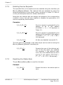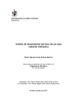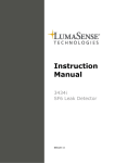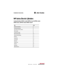
1
User Manual for 1309 Multipoint Sampler BE1285-15 Index ________________________________________________________________________ Index Index ................................................................................................................................... 2 1309 Multipoint Sampler ........................................................................................................ 3 SAFETY CONSIDERATIONS .................................................................................................. 4 Safety Considerations ....................................................................................................... 4 Chapter 1 Description and Functions ....................................................................................... 6 1.1 Description and Function .......................................................................................... 7 1.1.1 The Sampler System .......................................................................................... 7 1.2 Front Panel ............................................................................................................. 8 1.3 Rear Panel .............................................................................................................. 9 Chapter 2 Preparing to Use the 1309 .................................................................................... 10 2.1 Preliminary ........................................................................................................... 11 2.1.1 Environment and Handling ................................................................................ 11 2.1.2 Connecting the Mains Supply ............................................................................. 11 2.1.3 Checking the Power Cord .................................................................................. 11 2.1.4 Checking the Fuses .......................................................................................... 11 2.2 Connecting the 1309 to the System Controller .......................................................... 12 2.3 System Use .......................................................................................................... 13 2.3.1 Setting the Interface Address of the 1309 ........................................................... 14 2.4 Connecting Tubing to the 1309 ............................................................................... 16 2.4.1 Connecting Sampling Tubing ............................................................................. 17 2.4.2 Connecting External Filters to the Sampling Tubes ............................................... 18 2.4.3 Connecting a Water-trap Filter ........................................................................... 18 2.4.4 Connecting the Sampler Outlet to the Gas Monitor ............................................... 19 2.5 Connecting Temperature Transducers to the 1309 ..................................................... 20 Chapter 3 Operation ........................................................................................................... 21 3.1 Switching-On ........................................................................................................ 22 3.2 General Principles of Controlling the 1309................................................................. 22 3.2.1 Syntax for Interface Jobs .................................................................................. 22 3.2.2 Output Jobs – Requesting Information from the 1309 ........................................... 25 3.3 Using the Sampler System...................................................................................... 26 3.4 Temperature Measurement ..................................................................................... 27 3.5 Pressure Measurement ........................................................................................... 27 3.6 Checking the 1309 ................................................................................................. 27 3.6.1 Status? Interface Job........................................................................................ 27 3.6.2 Reset System Interface Job ............................................................................... 28 3.7 Error Conditions and Service Requests ..................................................................... 29 3.7.1 The Status Byte ............................................................................................... 29 3.7.2 Enabling Service Requests ................................................................................ 30 3.7.3 Resetting the Status Byte ................................................................................. 30 3.7.4 The Warning? Interface Job ............................................................................... 31 3.7.5 The Error? Interface Job ................................................................................... 32 Chapter 4 The IEEE/IEC Interface and Interface Job Overview ................................................. 34 4.1 Introduction .......................................................................................................... 35 4.1.1 IEEE Functions Implemented in the 1309 ............................................................ 35 4.2 Overview of 1309 Interface Jobs ............................................................................. 36 4.2.1 Sampler System Jobs ....................................................................................... 37 4.2.2 Temperature Measurement Jobs ........................................................................ 37 4.2.3 Pressure Measurement Jobs .............................................................................. 37 4.2.4 1309 Check Jobs .............................................................................................. 38 4.2.5 Error Condition and Service Request Jobs ........................................................... 38 4.2.6 Standardised Jobs ............................................................................................ 38 Chapter 5 Maintenance ....................................................................................................... 40 5.1 Cleaning the Instrument ..................................................................................... 41 5.2 Service and repair ............................................................................................. 41 ________________________________________________________________________ BE1285-15 1309 Multipoint Sampler LumaSense Technologies A/S Page 2 of 42 1309 ________________________________________________________________________ 1309 Multipoint Sampler From Serial number: 660-128 November 2011 ________________________________________________________________________ BE1285-15 1309 Multipoint Sampler LumaSense Technologies A/S Page 3 of 42 Safety Considerations ________________________________________________________________________ Safety Considerations SAFETY CONSIDERATIONS PLEASE READ THESE SAFETY CONSIDERATIONS CAREFULLY AND MAKE SURE YOU UNDERSTAND THEM PROPERLY BEFORE YOU START OPERATING THE 1309 MULTIPOINT SAMPLER. EXPLOSION HAZARD THE 1309 MULTIPOINT SAMPLER IS NOT DESIGNED FOR USE IN POTENTIALLY EXPLOSIVE ENVIRONMENTS. This means that the instrument must not be placed and operated in an area with a potentially explosive atmosphere. When monitoring potentially flammable or toxic gases it is essential that: 1) the instrument itself is placed in a well-ventilated area outside the potentially hazardous zone; and 2) that a sufficiently long tube is connected to the “Sampler Waste Air Outlet” so that the sampled gas is carried away to the open air or to an extraction and/or filtration unit. TO AVOID THE POSSIBILITY OF AN EXPLOSION, MONITORING OF FLAMMABLE GASES IN EXPLOSIVE CONCENTRATIONS MUST NEVER BE ATTEMPTED. AVOID WATER CONDENSATION IN THE INSTRUMENT. Liquids must be prevented from entering the instrument. It is therefore important that warm humid gases are not drawn into a cold instrument because condensation will take place. If such a situation is likely to occur you should ensure that the gases are drawn through water-trap filters before they enter the sampler channels of the 1309. This will remove water vapour in the gases and thus prevent condensation within the instrument. The water-trap filter should be used in the immediate environment of the instrument so it maintains either the same temperature, or a lower temperature than the instrument. Note: that some gases may be absorbed by the water trapped in the filter. This will reduce the gases’ concentration. ________________________________________________________________________ BE1285-15 1309 Multipoint Sampler LumaSense Technologies A/S Page 4 of 42 Safety Considerations ________________________________________________________________________ SAFETY CONSIDERATIONS The 1309 Multipoint Sampler complies with EN/IEC 61010-1 3rd Ed. (2010): Safety requirements for electrical equipment for measurement, control and laboratory use. To ensure safe operation and retain the 1309 in safe condition, note the following: APPLYING POWER Before using the 1309 check that the available mains voltage match the specified voltage and frequency for the instrument. SAFETY SYMBOLS The apparatus is marked with this symbol when it is important that the user refer to the associated warning statements given in the User Manual. Frame or Chassis Protective earth Hazardous Voltage WARNINGS Before connecting or disconnecting interface cables, switch off the power to all instruments. If the correct function or operating safety of the 1309 is impaired, secure the instrument against further use until the fault is repaired. Any adjustment, maintenance or repair of the internal parts of the 1309 under power must be avoided as far as possible; if unavoidable, it must only be done by qualified service personnel. Copyright © 2011 LumaSense Technologies A/S All rights reserved. No part of this publication may be reproduced or distributed in any form or by any means without prior consent in writing from LumaSense Technologies A/S, Ballerup, Denmark. ________________________________________________________________________ BE1285-15 1309 Multipoint Sampler LumaSense Technologies A/S Page 5 of 42 Chapter 1 ________________________________________________________________________ Chapter 1 Description and Functions November 2011 ________________________________________________________________________ BE1285-15 1309 Multipoint Sampler LumaSense Technologies A/S Page 6 of 42 Chapter 1 ________________________________________________________________________ 1.1 Description and Function 1.1.1 The Sampler System The pneumatic system of the 1309 is shown schematically in Fig.1.1. The sampler system is constructed of stainless steel (AISI 316) and PTFE (PolyTetraFluoroEthylene) tubing to minimize adsorption of samples. The system has 12 inlet channels, each with a solenoid valve. Each inlet channel has a tube-mounting stub on the front-plate of the 1309; to connect each channel to the respective sampling point. The 12 inlet channels converge into one; a three-way valve then directs the gas sample to the Gas Monitor for analysis, or through the external pump via the waste-air outlet on the 1309’s back-plate. The 1309’s sampler system functions efficiently, transporting gas samples from the sampling point at approximately 4 metres per second. However, this speed depends on the type of pump, the diameter of the tubing and the length of tubing attached to the 1309. An air-filter is attached to the end of each sampling tube to keep the samples free of particles. Fig. 1.1 A schematic diagram of the 1309’s pneumatic system. ________________________________________________________________________ BE1285-15 1309 Multipoint Sampler LumaSense Technologies A/S Page 7 of 42 Chapter 1 ________________________________________________________________________ 1.2 Front Panel Sampler: Fig.1.2 The front panel of the 1309 12 mounting stubs for connection of tubing to sampling points. Each stub is numbered, and has a correspondingly-numbered lamp. When the lamp is lit, it indicates that the corresponding sampling valve is open, see section 3.3. The Analyzer/Waste Air lamps indicate which way the internal 3 way valve is set, see section 3.3. Temperature Sensors Input: 6 inputs suitable for use with the INNOVA Air Temperature Transducer type MM0034, Surface Temperature Transducer MM0035 or Operative Temperature Transducer type MM0060. Interface: 3 lamps which indicate the function of the IEEE interface. If the Listen lamp is lit, the 1309 is receiving instructions or data from the system controller. If the Talk lamp is lit, the 1309 is outputting data. If the SRQ lamp is lit, the 1309 has generated a Service Request, see section 3.7. Full details of the IEEE Interface are given in Chapter 4. ________________________________________________________________________ BE1285-15 1309 Multipoint Sampler LumaSense Technologies A/S Page 8 of 42 Chapter 1 ________________________________________________________________________ 1.3 Rear Panel Fig.1.3 The rear panel of the 1309 100 - 240 Vac Fuses: T1.6AL 50-60Hz 70VA 00061-02-110311 AC Mains: A 3-pin connector accepting Power Cable for connection to a single phase AC mains supply with protective Earth. Mains Voltage: Connect 1309 to mains supply with 100-240 Vac, 50/60 Hz. Outlet to Analyzer: Mounting stub for connecting the sampler system of the 1309 to the inlet of an INNOVA Gas Monitor via tubing. See section 2.4.4. Usable models are 1302, 3425, 3426, 1312, 1314 or 1412. In the following referred to as “Gas Monitor”. Please contact LumaSense Technologies A/S for available models. Waste Air Outlet: Mounting stub for connecting the external pump to the 1309’s sampler system. See section 2.4.4. Interface IEEE-488: Digital interface designed in accordance with IEEE 4881978. The IEEE interface is identical in use to that described in IEC 625-1; full compatibility is only a matter of using the correct cables and connectors. For more detail about the IEEE/IEC interface, refer to Chapter 4. Device Address: Bank of 8 DIP switches which decide the 1309’s interface address. See section 2.3.1 for details of how to set the interface address. ________________________________________________________________________ BE1285-15 1309 Multipoint Sampler LumaSense Technologies A/S Page 9 of 42 Chapter 2 ________________________________________________________________________ Chapter 2 Preparing to Use the 1309 November 2011 ________________________________________________________________________ BE1285-15 1309 Multipoint Sampler LumaSense Technologies A/S Page 10 of 42 Chapter 2 ________________________________________________________________________ 2.1 Preliminary 2.1.1 Environment and Handling The Type 1309 Multipoint Sampler is designed for use in environments with temperatures between +5°C and +40°C (+41°F and +104°F) and with up to 90% relative humidity (non-condensing) at 40°C. Make sure to leave some space between the Rear Panel and the Wall, or other obstacles, to ensure easy access to the mains supply. No other special handling precautions are necessary. 2.1.2 Connecting the Mains Supply The 1309 is operated from a 50 to 60 Hz single phase AC mains supply. Voltage 100 – 240 Vac. Before connecting the mains supply, the following checks and adjustments should be performed to ensure safe operation of the 1309. 2.1.3 Checking the Power Cord Use the Power Cord delivered with the 1309 or check that the Cord used is rated minimum 10A / 250V. 2.1.4 Checking the Fuses Use a small flat-bladed screwdriver to prise open the flap surrounding the AC Mains switch. See Fig. 2.1. Fig.2.1. Accessing the 1309’s fuses ________________________________________________________________________ BE1285-15 1309 Multipoint Sampler LumaSense Technologies A/S Page 11 of 42 Chapter 2 ________________________________________________________________________ Again using the screwdriver, gently lever the fuse-holders out from their slots. See Fig. 2.2. Fig.2.2. Inserting the fuses into the 1309’s fuse holder Use two 1.6A slow-blow fuses (LumaSense No. VF0007), they are supplied with the instrument. When replacing the fuse-holders, ensure that the direction of the white arrows on each holder matches the arrows marked on the covering flap. 2.2 Connecting the 1309 to the System Controller The 1309 is connected to the System Controller by the IEEE interface bus, over which the 1309 receives the commands and data which control it. Further information about the cables available from LumaSense to connect the 1309 to the IEEE interface bus, and about the IEEE interface of the 1309, are given in section 4.1. ________________________________________________________________________ BE1285-15 1309 Multipoint Sampler LumaSense Technologies A/S Page 12 of 42 Chapter 2 ________________________________________________________________________ 2.3 System Use The 1309 combined with a Gas Monitor and a controlling computer provides a system that offers wide-ranging monitoring capabilities. The 1309 makes it possible to perform multipoint monitoring tasks in many different situations and environments, without changing the system components. An example of a multipoint, multi-gas monitoring system is shown in fig. 2.3. In such a system, the sampler system takes a sample of the return-air from the room, and delivers it to the 1412 for analysis. While the 1412 performs one analysis, the 1309 takes the next sample for analysis from the room. Fig. 2.3 A typical sampling system, shown with an application example. Up to 12 analyses can be performed simultaneously using one 1309. LumaSoft Gas Multipoint Innova 7850 Application Software gives control of all the functions of the system. LumaSense Technologies has a 7850 Application Software to give full coordination and control of all the sampling and monitoring functions of such a system. The application software package can control one 1309 unit and one 1412. ________________________________________________________________________ BE1285-15 1309 Multipoint Sampler LumaSense Technologies A/S Page 13 of 42 Chapter 2 ________________________________________________________________________ 2.3.1 Setting the Interface Address of the 1309 The 1309 uses a single interface address. The address is set using the bank of eight DIP switches on the rear panel of the 1309. The last five switches on the bank decide the interface address. These switches are marked A1 (the least significant bit) to A5 (the most significant bit). The switches represent binary values, as follows: If the switch is down, it represents a binary “0”. See Fig. 2.5. ________________________________________________________________________ BE1285-15 1309 Multipoint Sampler LumaSense Technologies A/S Page 14 of 42 Chapter 2 ________________________________________________________________________ Fig. 2.5. Dipswitch settings binary “0” If the switch is up, it represents a binary “1”. See Fig. 2.6. Fig. 2.6 Dipswitch settings binary “1” The default interface address of the 1309 is set to 01111 (decimal value 15), see Fig. 2.7. If this is not suitable for your system, use the switches to set an address appropriate to your system. ________________________________________________________________________ BE1285-15 1309 Multipoint Sampler LumaSense Technologies A/S Page 15 of 42 Chapter 2 ________________________________________________________________________ Fig. 2.7. Interface address 15 2.4 Connecting Tubing to the 1309 The 1309 is connected via tubing to: • the sampling points; • to the gas-monitor being used to analyse the gases that are sampled; • to the external pump. Note: the performance of the 1309’s sampling system is dependant on the type of external pump used and the length and diameter of the sampling tubing. Sampler tubing for use with the 1309 is available from LumaSense: polytetrafluoroethylene (PTFE), 50m roll, accessory number AF0614. Using this tubing material minimizes the risk of gases being adsorbed onto the tube’s surface, which would result in inaccurate measurements. WARNING! Avoid water condensation in the instrument. Liquids must be prevented from entering the instrument. It is therefore important that warm humid gases are not drawn into a cold instrument because condensation will take place. If such a situation is likely to occur, you must ensure that the gases are drawn through water-trap filters before they enter the sampler channels of the 1309. This will remove the water vapour in the gases and thus prevent condensation within the instrument. Use the water-trap filter in the immediate envi________________________________________________________________________ BE1285-15 1309 Multipoint Sampler LumaSense Technologies A/S Page 16 of 42 Chapter 2 ________________________________________________________________________ ronment of the instrument so it maintains either the same temperature, or a lower temperature than the instrument. See section 2.4.3 for details of how to fit a water-trap filter. 2.4.1 Connecting Sampling Tubing Before connecting sampling tubing to the 1309, determine approximately where the sampling points will be in the area to be monitored. This will allow you to estimate the length of tubing you need to connect to the mounting-stubs of the 1309. To connect sampling tubing (see Fig.2.8): Fig.2.8 Attaching sampling tubing to the 1309’s mounting stubs 1. Remove the knurled nut from the mounting stub of the sampler channel you wish to use, on the front panel of the 1309. 2. Push one end of the length of PTFE through the non-threaded end of the nut. 3. Push the end of the tubing onto the mounting stub as far as it will go, and secure the tube by re-tightening the knurled nut onto the threads of the mounting stub. ________________________________________________________________________ BE1285-15 1309 Multipoint Sampler LumaSense Technologies A/S Page 17 of 42 Chapter 2 ________________________________________________________________________ 2.4.2 Connecting External Filters to the Sampling Tubes The external filters, comprising filter, LumaSense accessory number DS2306, and fitting, LumaSense accessory number UD5041 (optional accessories), protect the 1309’s sampling airways from airborne particles such as dust, thus helping to prevent blockage of the airways. The filter unit is attached to the tubing as follows (see Fig.2.9): Fig.2.9 Attaching Fitting UD5041 and Filter DS2306 to sampling tubing 1. Push the Fitting UD5041 into the tubing. 2. Screw the short stub of the Filter DS2306 into the Fitting. 2.4.3 Connecting a Water-trap Filter The In-line Genie Membrane Separator (LumaSense order no. UA1365) avoids condensation in the sampling and measuring instruments. Use the filter in the immediate environment of the instrument so it maintains either the same temperature, or a lower temperature than the instruments. ________________________________________________________________________ BE1285-15 1309 Multipoint Sampler LumaSense Technologies A/S Page 18 of 42 Chapter 2 ________________________________________________________________________ Note: some gases may be absorbed by the water trapped in the filter. This will reduce the gases’ concentrations. To connect sampling tubing to the water-trap filter Push the sampling tubing into the connector as far as it will go and tighten the nut. Fig. 2.10 Attaching tubing to the In-line Genie Membrane Separator. Note: make sure that the gas flows through the filter in the direction indicated - shown by the arrows on the filter. To disconnect the sampling tubing Loosen the nut and pull the sampling tubing out of the connector. 2.4.4 Connecting the Sampler Outlet to the Gas Monitor This connection uses the same tubing (PTFE, LumaSense No. AF0614) as for the sampling tubes, section 2.4.1. The tubing is connected to the Outlet to Analyzer stub on the rear panel of the 1309, and to the Air Inlet stub on the rear panel of the Gas Monitor. The tubing is connected as described in section 2.4.1. ________________________________________________________________________ BE1285-15 1309 Multipoint Sampler LumaSense Technologies A/S Page 19 of 42 Chapter 2 ________________________________________________________________________ The Waste Air Outlet stub, next to the Outlet to Analyzer, (see fig. 1.3) stub on the rear panel of the 1309, connects the external pump to the 1309’s sampler system. If you do not wish the waste air from the pump to mix with the air in the room where the 1309 is positioned, connect a length of PTFE tubing (LumaSense no. AF0614) to the waste air outlet stub on the external pump and direct the tubing to a suitable exhaust-point: for example, out of a window. 2.5 Connecting Temperature Transducers to the 1309 The 1309 has 6 temperature-sensor inputs mounted on its front panel, (see fig. 1.2) suitable for direct use with the INNOVA Air Temperature Transducer MM0034, Surface Temperature Transducer MM0035 or Operative Temperature Transducer MM0060. ________________________________________________________________________ BE1285-15 1309 Multipoint Sampler LumaSense Technologies A/S Page 20 of 42 Chapter 3 ________________________________________________________________________ Chapter 3 Operation November 2011 ________________________________________________________________________ BE1285-15 1309 Multipoint Sampler LumaSense Technologies A/S Page 21 of 42 Chapter 3 ________________________________________________________________________ All tasks performed by the 1309 are controlled over the IEEE/IEC interface from a System Controller; there is no other control possibility. This chapter deals with the control of the 1309 from the user’s point of view; for details of the IEEE/IEC interface specifications, refer to Chapter 4 of this manual. Sections 3.1 and 3.2 deal with switching-on and the general principles of controlling the 1309. Sections 3.3 to 3.7 deal with the specific commands and requests, known as interface jobs, which set-up and control the 1309. Each interface job is dealt with by giving an example which states the effect of the job. For quick reference, an overview of all interface jobs is given in section 4.2 of this manual. 3.1 Switching-On The 1309 can be switched on using the AC Mains switch on the backplate. After switching-on, the 1309 is set as follows: • The sampling-valves closed. • Internal three-way valve set to Waste Air Outlet. 3.2 General Principles of Controlling the 1309 The 1309’s functions are controlled over the IEEE/IEC interface using a range of commands and data requests, each of which is specific to a particular function or item of data. These commands and requests are known as interface jobs. This section describes the structure of the interface jobs used to control the 1309. Further details about the IEEE/IEC interface of the 1309 are given in Chapter 4 of this manual. 3.2.1 Syntax for Interface Jobs Fig.3.1 shows a diagram representing a single interface job, sent from the system controller to the 1309. Each constituent part of the interface job is explained below. ________________________________________________________________________ BE1285-15 1309 Multipoint Sampler LumaSense Technologies A/S Page 22 of 42 Chapter 3 ________________________________________________________________________ Fig.3.1. General syntax diagram for interface jobs Job Headers The job header specifies the function you want the 1309 to perform. It consists of one or more words. The ASCII underline character “_” is used to separate individual words in the job header. For example: OPEN_SAMPLING_VALVE A hyphen “-“ or a full stop”.” can also be used to separate words in the job header. The words making up the job header do not need to be sent in full to the 1309; they can be shortened to a code-form, for example: OP_SA_VALVE O_S_V The minimum code for each job header is usually the first character of each word in the job header. This is written in bold characters in the list of interface jobs given in section 4.2 of this manual. The 1309 accepts job headers in both upper- and lower-case characters. The Data Field The data field contains further information specific to the interface job defined by the job header. The data field is separated from the job header by a space character (“SP”) or a comma “,”. In the following examples, the separator will always be the space character, represented by the symbol “”. The data field will normally contain a numerical value. For example: OPEN_SAMPLING_VALVE2 Some jobs may require more than one item of data. In this case, the data is given item by item, separated by commas. For example: OPEN_SAMPLING_VALVE2,3,4 ________________________________________________________________________ BE1285-15 1309 Multipoint Sampler LumaSense Technologies A/S Page 23 of 42 Chapter 3 ________________________________________________________________________ Numerical data for interface jobs sent to the 1309 can be in NR1, NR2 or NR3 form. This is a format for describing how the numerical data is represented, for example: NR1 data: 250 (number without decimal fraction or exponent) nent) NR2 data: 249.85 (number with decimal fraction, without expoNR3 data: 2.499E-2 (number with fraction and exponent). Generally, any of these data formats can be used, unless specifically stated otherwise in the interface job overview given in section 4.2. The number of characters in the non exponent part of the data field must not be greater than 8. Job Terminators Each interface job must have a terminator (signified by Te in Fig.3.1) which tells the 1309 that it has received the complete interface job. When the 1309 receives the terminator, it checks the whole job and, if it is a valid job, carries it out. The terminator for communication with the 1309 is an ASCII control character, such as “LF”. This is the default terminator character used in communication with the 1309. The terminator character can be changed, as follows. To select a terminator character other than the default, use the interface job Define_Terminator, followed by the decimal value of the character you wish to use. The possible terminator characters, with the corresponding decimal values, are shown in Table 3.1. DEF_TERMINATOR3<LF> Selects the control character ETX (decimal value 3) as the terminator character. All of the following interface job examples assume the use of “LF” as the terminator character. ________________________________________________________________________ BE1285-15 1309 Multipoint Sampler LumaSense Technologies A/S Page 24 of 42 Chapter 3 ________________________________________________________________________ Table 3.1. The range of ASCII terminator-characters which can be used in communication with the 1309 ASCII Character SOH STX ETX EOT ENQ ACK BELL BS HT LF VT FF SO SI DLE 3.2.2 Decimal Code 1 2 3 4 5 6 7 8 9 10 11 12 14 15 16 ASCII Character DC1 DC2 DC3 DC4 NAK SYN ETB CAN EM SUB ESC FS GS RS US Decimal Code 17 18 19 20 21 22 23 24 25 26 27 28 29 30 31 Output Jobs – Requesting Information from the 1309 Interface output jobs request specific data from the 1309. The output jobs allow checks of the 1309’s functions and set-up parameters. Output jobs consist of a job header followed by a question-mark; more specific information is requested by including a data field. An example of an output-job is: PRESSURE?<LF> To which the 1309 responds with the required data. The general syntax for data output from the 1309 is shown in Fig.3.2. Fig.3.2. General syntax diagram for data-output from the 1309 Generally, numerical data output from the 1309 is in NR2 form unless specifically stated otherwise in the interface job overview given in sec- ________________________________________________________________________ BE1285-15 1309 Multipoint Sampler LumaSense Technologies A/S Page 25 of 42 Chapter 3 ________________________________________________________________________ tion 4.2. The default terminator character used is the control character “<LF>”. The terminator character can be changed, as described in section 3.2.1. 3.3 Using the Sampler System Using the 1309’s sampler system, see Fig. 1.1, to deliver a sample to the Gas Monitor is a 3-stage process: 1. The required sample valve is opened; all other sample valves are closed automatically. 2. The sample valve is connected to the external pump via the 1309’s internal 3-way valve, allowing the waste air to be exhausted from the sample channel (via the Waste Air Outlet, section 2.4.4) and drawing the new sample. 3. When the new sample has been drawn to the 1309, the internal 3-way valve is set to direct the sample to the Gas Monitor. The Gas Monitor’s pump draws the sample for analysis. While the Gas Monitor is analysing this sample, the next sample can then be drawn ready for the next analysis. Three interface jobs control the sampling process. Examples: OPEN_SAMP_VALVE1<LF> CONNECT_SAMP_VALVE TO_SAMPLING_PUMP<LF> CONNECT_SAMP_VALVE TO_MONITOR<LF> Opens sample valve 1, closes all other sample valves. If no sample valve is specified, all sample valves are closed. Connects the sample valve to the external pump, and exhausts the waste air from the sample channel. Directs the new sample to the Gas Monitor for analysis. ________________________________________________________________________ BE1285-15 1309 Multipoint Sampler LumaSense Technologies A/S Page 26 of 42 Chapter 3 ________________________________________________________________________ The time taken to draw a sample depends upon the type of external pump and the diameter and length of the sampling tube. 3.4 Temperature Measurement The temperature measured by the Air Temperature Transducer MM0034, Surface Temperature Transducer MM0035 or Operative Temperature Transducer MM0060 is read out from the 1309 as follows: Example: SENSOR_TEMP?1<LF> Reads-out the temperature data in °C from the temperature transducer connected to input number 1. If no transducer is connected to the particular input, the 1309 outputs 100°C. 3.5 Pressure Measurement The 1309 contains a pressure transducer. The atmospheric pressure around the multiplexer is read out as follows: Example: PRESSURE?1<LF> Reads-out the atmospheric pressure in kPa. 3.6 Checking the 1309 3.6.1 Status? Interface Job This job reads-out the 1309’s current mechanical condition. The 1309’s current condition is shown as a “flag”, i.e. a word-value comprising 16 bits, each of which represents a specific mechanical component. If a bit is set, the 1309 is currently using the corresponding component. The flag is output from the 1309 as the total of the decimal equivalents of the binary values of the bits which are set. See Table 3.2 for the components represented by each bit in the Status flag, and their corresponding decimal values. ________________________________________________________________________ BE1285-15 1309 Multipoint Sampler LumaSense Technologies A/S Page 27 of 42 Chapter 3 ________________________________________________________________________ Table 3.2. The 1309’s Status Flag. Each bit represents a particular 1309 component; when set, the 1309 is currently using that component. Bit no. 1 2 3 4 5 6 7 8 9 10 11 12 13 14 15 16 Status Flag Dec. Bit name value 1 Sampling valve 2 Sampling valve 4 Sampling valve 8 Sampling valve 16 Sampling valve 32 Sampling valve 64 Sampling valve 128 Sampling valve 256 Sampling valve 512 Sampling valve 1024 Sampling valve 2048 Sampling valve 4096 3-way valve 8192 Not used 16384 Not used 32768 Not used Current function when set 1 2 3 4 5 6 7 8 9 10 11 12 Sampling valve 1 open Sampling valve 2 open Sampling valve 3 open Sampling valve 4 open Sampling valve 5 open Sampling valve 6 open Sampling valve 7 open Sampling valve 8 open Sampling valve 9 open Sampling valve 10 open Sampling valve 11 open Sampling valve 12 open 3-way valve set to analyzer Not used Not used Not used Example: STATUS?<LF> Outputs the Status flag of the 1309 as described above. Refer to Table 3.2 for the decimal values of each bit. Refer also to the examples given below. If the 1309 outputs 4352, using Table 3.2 shows that 4352 = 256 + 4096. Therefore, bits 9 and 13 are set. The mechanical condition of the 1309 is: sampling valve number 9 open, and 3-way valve set to Analyzer. 3.6.2 Reset System Interface Job This job restarts the 1309. The 1309 restarts as described in section 3.1. Resetting the 1309 cancels any task which the 1309 was performing prior to the reset. Example: RESET_SYSTEM<LF> Resets the 1309. ________________________________________________________________________ BE1285-15 1309 Multipoint Sampler LumaSense Technologies A/S Page 28 of 42 Chapter 3 ________________________________________________________________________ 3.7 Error Conditions and Service Requests If an error arises in the 1309’s hardware, processor system or software, the 1309 can signal the system controller by generating a Service Request. The exact nature of the error condition can then be investigated by using the Warning? or Error? interface jobs. 3.7.1 The Status Byte The status byte is an eight-bit byte, read out by the system controller as part of the serial poll sequence. The status byte gives the first indication of the cause of the service request. The status byte for the 1309 is shown in Table 3.3. For an error to generate a Service Request, the corresponding bit in the status byte must be enabled to request service. The procedure for this is described in the following section. When a service request is enabled, all bits in the status byte except bit 6 are reset by a serial poll read-out or resetting the status byte. Bit 6 is only reset when the abnormal condition of the 1309 (identified by the Warning? or Error? interface jobs, sections 3.7.4 to 3.7.5) is corrected. When a service request is generated, bit 7 of the status byte is always set; it cannot be disabled. Table 3.3 The 1309’s Status Byte showing the error conditions which results in the individual bits being set Status Byte Bit no. 1 2 3 4 5 6 7 8 Error Condition Dec. Value 1 Not used 2 Set when the 1309 has completed a reset 4 Set when the 1309 has completed an interface job 8 Not used 16 Set when the 1309 has not completed the previous interface job when a new job is read-in 32 The 1309 is in an abnormal condition. The interface jobs Warning? or Error? give more information about the abnormal condition – see sections 3.7.4 and 3.7.5. 64 Indicates the 1309 has set the interface SRQ line 128 Not used ________________________________________________________________________ BE1285-15 1309 Multipoint Sampler LumaSense Technologies A/S Page 29 of 42 Chapter 3 ________________________________________________________________________ 3.7.2 Enabling Service Requests The specified bits in the status byte are enabled using the interface job Service_Request_Enable. The required bits are specified by using the decimal equivalent of their binary value, as shown in Table 3.3. See also the job examples below for further clarification. Note that the relevant bits are always set whenever the corresponding condition occurs; this job only enables or disables the generation of a service request by that condition. Examples: S_R_E32<LF> Service request is generated by the setting of bit 6 (bit pattern 00100000 = 25 = 32 decimal) in Table 3.3. S_R_E160<LF> Service request is generated by the setting of bit 6 and bit 8 (bit pattern 10100000 = 25 + 27 = 32 + 128 = 160 decimal). S_R_E0<LF> All bits are disabled (except bit 7). The bits which are enabled in the status byte can be read-out using the Service_Request_Enable? interface job: S_R_E?<LF> 3.7.3 Outputs the sum of the decimal values of the bits which are enabled. For example, if the decimal readout is 48, the enabled bits are bit 5 and bit 6 (bit pattern 00110000 = 25 + 26 = 16 + 32 = 48 decimal). Resetting the Status Byte The job Reset_Status_Byte is used for this task. Example: R_S_B<LF> Resets the bits in the status byte to zero. ________________________________________________________________________ BE1285-15 1309 Multipoint Sampler LumaSense Technologies A/S Page 30 of 42 Chapter 3 ________________________________________________________________________ 3.7.4 The Warning? Interface Job This job reads-out an 8-bit byte (the Warning Flags) which gives information about error conditions which affect the efficient operation of the 1309. The 1309 is still able to operate, but the error should be rectified as soon as possible. The Warning Flag byte is shown in Table 3.4. Table 3.4 The 1309’s Warning Flags byte Bit no. 1 2 3 4 5 6 7 8 WARNING FLAGS Dec. Value Flag Description 1 Reset Done Flag 2 Temperature Flag 4 Power Fail Flag 8 Not used 16 Not used 32 Not used 64 Not used 128 Not used Warning Flags are set when either the 1309’s self-check procedures or the Check_System interface job identify an error condition. This in turn sets bit 6 of the Status Byte (generating a service request, if enabled) to indicate that an error condition exists. The Warning? job can then give more information about the cause of the error condition. Example: Warning?<LF> Outputs the Warning Flags from the 1309. A “1” indicates that the flag is set; a “0” indicates the flag is not set. The conditions which cause the Warning Flags to be set, and the appropriate action to be taken, are dealt with in turn below. Reset Done Flag Indicates that the 1309 has completed a reset, following either the Reset_System interface job (section 3.6.2) or switching on the 1309. This flag is reset when the Warning Flags are read-out from the 1309. Temperature Flag Is set when the internal temperature of the 1309 is outside the range +2°C to +60°C. The 1309 must not be used until the internal temperature is within the normal operating limits of +5°C to +40°C. This flag is reset when the internal temperature is again within the normal operating limits, or by resetting the 1309, or switching the 1309 off and the on. ________________________________________________________________________ BE1285-15 1309 Multipoint Sampler LumaSense Technologies A/S Page 31 of 42 Chapter 3 ________________________________________________________________________ Power Fail Flag Is set if the power is outside the range 13.25V to 15.75V. This flag is reset when the voltage is back within the above range, or by resetting the 1309, or switching the 1309 off and then on. If the error is persistent, have the 1309 serviced. 3.7.5 The Error? Interface Job This job reads-out an 8-bit byte (the Error Flags) which gives information about errors which cause the 1309 to stop working. If any of these errors exist, the 1309 is unable to function until the error is rectified. The Error Flag byte is shown in Table 3.5. Table 3.5 The 1309’s Error Flags byte Bit no. 1 2 3 4 5 6 7 8 ERROR FLAGS Dec. Value Flag Description 1 ADC Flag 2 RAM Flag 4 PROM Flag 8 Not used 16 Not used 32 Job Specification Error 64 Software Error Flag 128 Power up Flag Error Flags are set when the 1309’s self-check procedures identify an error condition. This in turn sets bit 6 of the Status Byte (generating a service request, if enabled) to indicate that an error condition exists. The Error? job can then give more information about the cause of the error condition. Example: Error?<LF> Outputs the Error Flags from the 1309. A “1” indicates that the flag is set; a “0” indicates the flag is not set. The conditions which cause the Error Flags to be set are dealt with in turn below. ADC Flag Is set when the ADC (analogue-digital converter) develops an error. This results in a software-error, which automatically resets the 1309. The flag is reset by reading-out the Error Flags, or by switching the 1309 off and then on. If the error persists, have the 1309 serviced. ________________________________________________________________________ BE1285-15 1309 Multipoint Sampler LumaSense Technologies A/S Page 32 of 42 Chapter 3 ________________________________________________________________________ RAM Flag Indicates that the RAM (random access memory) of the 1309, which stores the 1309’s set-up data, has been corrupted. The flag is reset by switching the 1309 off and then on. If the error persists, have the 1309 serviced. PROM Flag Indicates that the CRC (cyclic redundancy check) for the PROM (programmable read-only memory) has identified incorrect data. The flag is reset by switching the 1309 off and then on. If the error persists, have the 1309 serviced. Job Specification Flag Is set if an interface job sent to the 1309 is not recognised. This can be due to an incorrect job header, incorrect syntax, or incorrect or missing data. A job cannot be carried out by the 1309 if this flag is set. The job’s syntax should be checked carefully and the job sent again. The flag is reset by reading-out the Error Flags, or by switching the 1309 off and then on. Software Error Flag Is set when the 1309’s software develops an error when running. When this flag is set, the 1309 is reset automatically. The flag is reset by reading-out the Error Flags, or by switching the 1309 off and then on. If the error persists, have the 1309 serviced. Power up Flag This flag is set when the 1309 has been switched off and then on. This flag is reset by reading-out the Error Flags. If the error persists, have the 1309 serviced. ________________________________________________________________________ BE1285-15 1309 Multipoint Sampler LumaSense Technologies A/S Page 33 of 42 Chapter 4 ________________________________________________________________________ Chapter 4 The IEEE/IEC Interface and Interface Job Overview November 2011 ________________________________________________________________________ BE1285-15 1309 Multipoint Sampler LumaSense Technologies A/S Page 34 of 42 Chapter 4 ________________________________________________________________________ 4.1 Introduction The digital interface of the 1309 Multipoint Sampler is designed according to ANSI/IEEE Std 488-1978, “IEEE Standard Digital Interface for Programmable Instrumentation”. The only significant difference between this and the digital interface of IEC Publication 625-1 is in the type of connector specified; a full range of connectors and adaptors from LumaSense ensures compatibility between instruments fitted with either connector. The 1309 is connected to other instruments with IEEE/IEC interfaces using the following LumaSense cables and connectors. • Cable AO0265, which has an IEEE standard connector at each end, connects the 1309 to other instruments equipped with the IEEE connector. • Cable WL0845, which has IEEE connectors at both ends, is used to connect the 1309 to the IEEE connector of the Gas Monitor. The codes and formats used in sending and receiving data to and from the 1309 over the IEEE/IEC interface have been designed according to the recommendations of IEEE Std 728-1982, “IEEE Recommended Practice for Code and Format Conventions (For Use with ANSI/IEEE Std 488-1978)”. Note in particular that the 1309 carries out all communications other than defined bus command sequences using ASCII (ISO 7-bit) coded messages. It is important to note that although the digital interface of the 1309 is designed according to IEEE Std 488 and follows the recommendations of IEEE Std 728, absolute compatibility with IEEE/IEC interfaces designed by other manufacturers cannot be unconditionally guaranteed, since differences can occur within the limits of the specifications. Any problems encountered, however, will be of a software rather than a hardware nature. Where compatibility is in doubt, contact your local LumaSense representative for further information. 4.1.1 IEEE Functions Implemented in the 1309 The interface of the 1309 implements the following functions as specified in IEEE-488. The sections referred to are the relevant sections of the IEEE Std 488-1978 which specify the functions. The equivalent clauses of IEC Publication 625-1 are given in parentheses. Section 2.3 Source Handshake (SH) Interface Function, (Clause 6) SH 1 – complete capability ________________________________________________________________________ BE1285-15 1309 Multipoint Sampler LumaSense Technologies A/S Page 35 of 42 Chapter 4 ________________________________________________________________________ Section 2.4 Acceptor Handshake (AH) Interface Function, (Clause 7) AH 1 – complete capability Section 2.5 Talker (T) Interface Function, (Clause 8) T 5 – basic talker, serial poll, talk only mode, unaddress if MLA Section 2.6 Listener (L) Interface Function, (Clause 9) L 3 – basic listener, listen only mode, unaddress if MTA Section 2.7 Service Request (SR) Interface Function, (Clause 10) SR 1 – complete capability Section 2.9 Parallel Poll (PP) Interface Function, (Clause 12) PP 1 – complete capability Section 2.10 Device Clear Interface Function, (Clause 13) DC 1 – complete capability All other functions – no capability For further details of the above functions refer to the relevant section of the IEEE or IEC standards. 4.2 Overview of 1309 Interface Jobs In this section, each 1309 interface job is grouped according to its function, with a short description of its effect. The correct syntax for each job is given, with the minimum code for each job-header, in bold upper-case characters. The data for input jobs can be in NR1, NR2 or NR3 format, see section 3.2.1, unless specifically stated otherwise. The data for output jobs is in NR2 format unless specifically stated otherwise. ________________________________________________________________________ BE1285-15 1309 Multipoint Sampler LumaSense Technologies A/S Page 36 of 42 Chapter 4 ________________________________________________________________________ 4.2.1 Sampler System Jobs These jobs control the 1309’s sampler system. Further information about these jobs is given in section 3.3. Table 4.1 The interface jobs which control the 1309’s sampler system Job Header Open_Sampling_Valv e Connect_Sampling_Valv e 4.2.2 Data Up to 12 samplingvalve numbers To_Monitor To_Sampling_Pump Effect on 1309 Opens the specified sampling valves Routes the air-sample either to the gas monitor, or to the Waste Air Outlet. Temperature Measurement Jobs This job controls temperature measurement with the 1309. Table 4.2 The interface jobs which control the 1309’s temperaturemeasurement function. Job Header Sensor_Temperature ? 4.2.3 Data Specific temperaturesensor number Effect on 1309 Reads-out the temperature (°C) at the specified temperature-sensor. Pressure Measurement Jobs This job measures the atmospheric pressure around the 1309. Table 4.3 The interface jobs which control the 1309’s pressuremeasurement function. Job Header Pressure? Data No data Effect on 1309 Reads-out the atmospheric pressure (kPa) surrounding the 1309. ________________________________________________________________________ BE1285-15 1309 Multipoint Sampler LumaSense Technologies A/S Page 37 of 42 Chapter 4 ________________________________________________________________________ 4.2.4 1309 Check Jobs Table 4.4 The interface jobs which check the 1309’s functions. Job Header Status? Data No data. Reset_System No data. Effect on 1309 Reads-out the 1309’s status-flag. Resets the 1309. For further information, refer to section 3.6. 4.2.5 Error Condition and Service Request Jobs These jobs allow the identification of error conditions in the 1309. For further information, refer to section 3.7. Table 4.5 The interface jobs which investigate error conditions and allow generation of service requests. 4.2.6 Job Header Service_Request_Enable Service_Request_Enable ? Reset_Status_Byte Data Decimal value of bits you want to enable. No data Warning? No data. Error? No data No data. Effect on 1309 Selectively enables bits in the status byte. Reads-out from the 1309 the enabled bits of the status byte. Resets all the bits of the status byte to zero. Reads-out the 1309’s Warning flags. Reads-out the 1309’s Error flags. Standardised Jobs These jobs do not directly affect the operation of the 1309. The Define_Terminator job is detailed in section 3.2.1. The Output_Header job is detailed in section 3.2.2. The jobs with syntax of the type “*RST” are standardised IEEE 488.2 jobs. Most of these jobs are identical to normal 1309 jobs in operation; the function description refers you to the appropriate 1309 job. ________________________________________________________________________ BE1285-15 1309 Multipoint Sampler LumaSense Technologies A/S Page 38 of 42 Chapter 4 ________________________________________________________________________ Table 4.6 Standardised interface jobs which perform various secondary functions of the 1309. Job Header Define_Terminator Data Decimal value of the ASCII control character Identify? Output_Header No data EXclusive Inclusive *IDN? No data. *RST No data. *SRE *SRE? No data *STB? No data *TST? No data Effect on 1309 Selects the terminator character for interface jobs. Outputs INNOVA 1309 Disables/enables the 1309 to output the minimum code of the job header with the appropriate data, in response to the output jobs listed, section 3.2.2. Outputs INNOVA 1309,0,VPXXXX Identical to Reset_System. Identical to the job Service_Request_Enable. Identical to the job Service_Request_Enable? Reads-out the status byte from the 1309. Indicates if the Warning or Error flags are set. The 1309’s condition is given as follows; 0: Normal 1: Warning flag(s) set -1: Error flag(s) set The flags can then be read-out using the Warning? or Error? jobs. ________________________________________________________________________ BE1285-15 1309 Multipoint Sampler LumaSense Technologies A/S Page 39 of 42 Chapter 5 ________________________________________________________________________ Chapter 5 Maintenance November 2011 ________________________________________________________________________ BE1285-15 1309 Multipoint Sampler LumaSense Technologies A/S Page 40 of 42 Chapter 5 ________________________________________________________________________ 5.1 Cleaning the Instrument It is recommended to clean the Instrument using a soft damped cloth. 5.2 Service and repair The Type 1309 Multipoint Sampler is designed and constructed to provide the user with many years of safe, trouble-free operation. However, should a fault occur which impairs its correct function and operating safety, then it should be immediately disconnected at the mains source and secured against further operations. For repair contact your local LumaSense Technologies A/S service representative. Under no circumstances should repair be attempted by persons not qualified in the service of electronic instrumentation. ________________________________________________________________________ BE1285-15 1309 Multipoint Sampler LumaSense Technologies A/S Page 41 of 42 1309 LumaSense Technologies A/S Energivej 30 DK-2750 Ballerup, Denmark Tel.:(+45) 44 20 01 00 Fax: (+45) 44 20 01 01 http://www.lumasense.dk