1
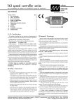
VERY IMPORTANT NOTE, READ CAREFULLY This device is a low power modulator for cable distribution of audiovideo signals. Use of this device for other purposes (e.g., wirelessly) may be in violation of local laws/regulations, depending on your area. If unsure, please check with your local telecommunications authorities. Under no circumstances should it be used in violation of any such laws/regulations. The responsibility for legal/proper usage rests solely on you! For technical support write to: [email protected] or ASPiSYS Ltd., POB 14386, Athens 115 10, Greece (EU) Or call: (+30) 210 771-9544 FAX: (+30) 210 771-4983. We are in the GMT+2 time zone. Technical Specifications RF SECTION Output Frequency 45 MHz to 860 MHz Visual Carrier Stability ±1KHz (Standard Channels) Aural Carrier Stability ±1KHz Antenna Connector F type female Output Level 80dBµV Output Impedance 75 Ω Audio Level Control Factory preset RF video/audio modulation system DSB VIDEO SECTION RED PHONO JACK Input Type Analog Negative Sync. Composite Video PAL – NTSC – SECAM (L) Input Level 0.7 Vp-p to 1.5 Vp-p for 87.5% modulation Input Impedance 75 ohms, unbalanced Frequency Response ±1.2 dB Signal to Noise Ratio >60dB Different Gain ±3% Different Phase ±3º AUDIO SECTION WHITE PHONO JACK Input Level 0.35V RMS for 25 KHz peak deviation Input Impedance >10KΩ unbalanced Pre-emphasis 75 or 50 µS auto-settled for country system Frequency Response 30Hz – 15KHz 0.75 dB Total Harmonic Distortion <1.0% TVSENDER MODULATOR v1.15 Modulator System for Television Usage Instructions, December 18, 2010 Copyright © 2009-2011 by ASPiSYS Ltd. Manufactured by: ASPiSYS Ltd. P.O. Box 14386, Athens 11510, GREECE (EU) http://www.aspisys.com GENERAL SECTION DC Input Power 0.5 Watt max DC Voltage 9 – 13.8V (Center positive 2.1mm plug) User manual TVSENDER1, 2009-2011 ASPiSYS Ltd. User manual TVSENDER1, 2009-2011 ASPiSYS Ltd. Connect audio to the white RCA jack. Connect video to the red RCA jack. Connect the F-Type antenna output for signal distribution. Connect a power supply of 9-12VDC (center positive) to the corresponding jack. The unit has a single push button and a triple LED. The button is located between the power supply jack and the RF (antenna) connector, while the LED is between the two RCA jacks. The bottom side is the one with the screws. The button has triple function: o o o If kept pressed while powering up the unit, instead of changing channels (see below), we will be changing sound systems. When pressed for less than 2 seconds, the modulator output will toggle between RCA and TEST (a black screen with two vertical white bars and 1 KHz sound). In TEST mode one or more LED remain on. In normal (RCA input) mode the LED go off alsmost immediately. When pressed for more than 2 seconds the transmission channel (or sound system) will start changing for as long as we keep the button firmly pressed. The LED will light up according to the following sequence depending on the frequency band (left column), or sound system (right column) the unit is currently at: If changing channels o VHF I o VHF II o UHF o S-VHF Low o S-VHF Hi If changing systems or PAL/BG or PAL/DK or NTSC/MN or PAL/I or SECAM/L LEDs Lower LED Middle LED Upper LED Lower + Middle LEDs Middle + Upper LEDs When we change channel(s) or sound system(s) the triple LED will remain lit (according to the band or sound system as described above) which means we are in TEST mode. To save the current settings in memory we press the button once more (briefly). The LEDs will go off which means we are in normal mode. From now on, the unit will always start at the programmed channel so that after a power failure it will return to the same channel it was before. Thank you for purchasing the TVSENDER MODULATOR by ASPiSYS Ltd. The TVSENDER MODULATOR is a broadband modulator for television. The unit requires 912VDC for operation. User manual TVSENDER1, 2009-2011 ASPiSYS Ltd. User manual TVSENDER1, 2009-2011 ASPiSYS Ltd.