1
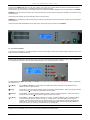
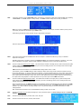
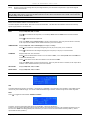
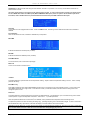
FASM1S PLL FM TRANSMITTER User’s Guide (Please read carefully before using for the first time!) Copyright © 2014 by ASPiSYS Ltd. FASM1S FM TRANSMITTER USER’S GUIDE 1. Preliminary Instructions ASPiSYS Ltd WARNING: WARNING: ASPiSYS Ltd 2. Warranty ASPiSYS Ltd ASPiSYS Ltd ASPiSYS Ltd 5 ASPiSYS Ltd ASPiSYS Ltd DO NOT RETURN UNITS WITHOUT OUR PRIOR AUTHORIZATION AS THEY WILL BE REFUSED! 4. Be sure to enclose a written technical report where mention all the problems found and a copy of your original invoice establishing the starting date of the warranty. Replacement and warranty parts may be ordered from the following address. Be sure to include the equipment model and serial number as well as part description and part number. Copyright © 2014 ASPiSYS Page 2 of 12 FASM1S FM TRANSMITTER USER’S GUIDE 3. First Aid 3.1 Treatment of electrical shocks 1 1 2 2 3 4 3 4 5 5 . . . . 3.2 Treatment of electrical Burns . . . . . If medical help will not be available within an hour and the victim is conscious and not vomiting, give him a weak solution of salt and soda: 1 level teaspoonful of salt and 1/2 level teaspoonful of baking soda to each quart of water (neither hot nor cold). DO NOT give alcohol. Copyright © 2014 ASPiSYS Page 3 of 12 FASM1S FM TRANSMITTER USER’S GUIDE . . . . . . 3. General information FASM1S-xxx is an FM analog broadcasting exciter / transmitter for the 87.5 – 108MHz band. It achieves high stability thanks to the latest technology PLL-based design. It has also an embedded FM STEREO Encoder circuit, to provide a total solution for any broadcaster. Power levels are denoted from the suffix numbers after the FASM1S. For example FASM1S-250 is the 250W Nominal RF output model (capable to work up to 300W max) & the FASM1S-500 is the 500W Nominal RF output model (capable of up to 600W max output). To operate you must first connect power 230VAC (or, via internal selection, it can work with 115VAC). To avoid damage, always operate the unit with the RF Out connected to an antenna with Z = 50 Ohm, or a 50 Ohm ‘dummy load’ that can withstand the maximum power level of your transmitter. NEVER USE IT WITHOUT A 50 OHM LOAD AT THE RF OUTPUT! FASM1S-xxx contains a low-pass filter that reduces the harmonic emissions to below the limits allowed by international regulations (CCIR, FCC or ETSI), and can therefore be Another important feature of the FASM1S is its great simplicity of construction and use. The FASM1S was designed to be modular. Its various functions are run from modules directly connected to each other with male and female connectors or with flat cables ending in connectors. This type of design makes maintenance operations and any required module replacement easier. The RF power section uses one high power double MOSFET able to deliver 300W. The working frequency is assured by a thermally-compensated reference oscillator working within a phase-locked loop (PLL). The FASM1S reaches frequency lock at any selected frequency in less than 30 seconds. It has also separate audio inputs for balanced & unbalanced AF signals, so there is no need to make any “balanced to unbalanced modification” to your studio wiring. Just connect your audio source to the corresponding Left and Right inputs (either front panel BNC jacks for unbalanced or at the XLR rear panel connectors for balanced signals). The unit will encode the stereo signals from either of them to a stereophonic MPX FM signal or, if selected, to a standard mono transmission. Please note that the firmware in the unit covers several different models. Therefore, some options may not be available in your unit. IMPORTANT: To prevent wrong settings before reading the manual, the unit may be initially set to the word ASPISYS so that you may not adjust the settings without knowing the password. If you wish to remove or change the password, see the corresponding section. Due to the continuously evolving firmware, it’s possible that some of the screen shots are not exactly the same on your unit. On rear panel are the IEC type AC Mains connector, balanced audio input XLR connectors, the RF output “N” type female connector, telemetry RS-232 connector and two BNC inputs for modulated signals on subcarriers from external stereo encoders and for RDS (Radio Data Systems) transmission. For FASM1S-500 there is no need to change any internal switch as it accepts 85-265VAC directly. For FASM1S-300, some serial numbers have a PSU with an internal voltage selector that allows the use of the transmitter with different AC mains voltage. Please ask ASPiSYS Ltd before attending to use the transmitter in a different country than the one for which it was ordered. 5.1 Preparation Unpack the exciter, and before doing any other operation, be sure it has not been damaged during transport. In particular check that all connectors are in perfect condition. Copyright © 2014 ASPiSYS Page 4 of 12 FASM1S FM TRANSMITTER USER’S GUIDE Check that the FASM1S-xxx switch is in the "OFF" position. The exciter has no other switches except the front panel main switch for powering up the unit, and when off, it completely interrupts the mains power supply. Connect the RF output of the exciter to the antenna cable or to a fictitious load able to dissipate the power generated by the FASM1S WARNING: In case the load is not present, don’t touch the RF output connector during the equipment operation to avoid electric shock and electrocution. Connect the mains cable to the proper VDE base, placed on the rear panel. WARNING: It is crucial that the mains system being provided with grounding to ensure both the operator’s safety and correct operation of the equipment. Connect the audio cable and RDS/SCA of the signal source to the proper input connectors of the FASM1S 5.2 Use of the transmitter Turn ON the front-panel switch. The self-illumination of the switch should light, showing that AC mains voltage is present. Now you are ready to operate the FASM1S as follows: OPERATION FASM1S front panel features a 20-character by 4-line LCD and a 4-button keyboard, aside the 2 BNC AF inputs. When powered up, the LCD displays a brief version and copyright message followed by the current transmission frequency. The keyboard buttons (MENU, UP, DOWN, and ENTER) which, depending on the keyboard type, may appear verbally or symbolically, are described next: [] / [Menu] Acts as Menu, or Escape. It cycles through the possible menu screens (sequence shown farther below) or selections within a single menu item. [] / [Up] Acts as Up. It cycles through the possible choices in a forward or upward direction. Menus with only two possible choices use the [] key instead to toggle between the two options. [] / [Down] Acts as Down. It cycles through the possible choices in a reverse or downward direction. Menus with only two possible choices use the [] key instead to toggle between the two options. [] / [Enter] Acts as Enter. It enters the Settings screen from any screen. If inside the Settings screen, it enters the editing mode for the specific item the cursor is currently on. If editing an item, it stops the editing and accepts the changes. For menu items that have only two possible options (e.g., toggle switches), pressing [] toggles the current option. Note: Some choices may become active immediately when selected with the [ ] / [] buttons while most options (e.g., frequency) are activated only by pressing [ ]. INFORMATIONAL ITEMS All pages show a combination of at most four of the following predefined informational items. Copyright © 2014 ASPiSYS Page 5 of 12 FASM1S FM TRANSMITTER USER’S GUIDE FRQ: A line which shows the current OnAir/OffAir status, the frequency of operation in MHz and the indicator [ST] when operating in Stereo Mode. The OnAir indicator is always steady. The OffAir indicator always blinks to draw your attention. Note: The unit may go OffAir automatically based on certain conditions. For example, excessive reflective power (over the pre-set limit) will cause the transmitter to go to OffAir mode.) While keeping the Up/Down button pressed, an [>] or [<] indication will appear. When the output level is at its highest limit, [H] will appear, and when it is off, [O] will appear. MOD: This screen looks the same as the FRQ screen with one exception. Instead of the REF line (3rd line), a modulation adjustment bar appears. Modulation adjustment is possible by pressing the Up/Down buttons until the desired modulation is achieved. The current level is indicated by a bar-graph, while the actual modulation is displayed on the 4th line as with the FRQ screen. FWD: Shows the measured forward power in Watts. The measurement is based on average (AVG) or peak-envelope-power (PEP) reading (only for AM systems), which is settable by the user in the Settings Screen, but it normally should not be changed from the manufacturer’s preset value. FWD measurements are based on the ‘PowerMeterMode’ setting of either ‘AVG’ or ‘PEP’. The brackets [ ] next to the FWD reading is used to display the status while turning the RF output level Up/Down (see the FRQ screen description). In previous versions of the firmware, a number appeared inside the [ ] which was a rough indication of the currently selected output level but since this number did not have any linear correspondence with the actual output level, it was found to be confusing for many users, and so it was replaced with a more intuitive method of showing when the RF output level is being adjusted. The RF output level can only be seen by the actual FWD measurement. REF: Shows the measured reflected power in Watts. The measurement is based on average (AVG) or peak-envelope-power (PEP) reading (only for AM systems), which is settable by the user in the Settings Screen, but it normally should not be changed from the manufacturer’s preset value. Next to the reflected power, an ALERT message may be displayed, whenever the reflected power goes above the ‘Lim REF’ setting, which may be changed from the manufacturer’s preset value by the user. The ALERT message blinks to draw your attention. If you have turned the ‘Sounding’ setting to ‘On’ a very discrete ticking sound will be heard while the ALERT message flashes. REF measurements are based on the ‘PowerMeterMode’ setting of either ‘AVG’ or ‘PEP’. Mod: Shows the modulation level as peak percentage (0 to 120%) and as bar graph. The 100% reading is set for +/-75 KHz FM deviation Date: Shows the current date as Day-of-week, date, month, and year. Time: Shows the current time as hours, minutes, and seconds. Copyright © 2014 ASPiSYS Page 6 of 12 FASM1S FM TRANSMITTER USER’S GUIDE Temp: Shows the current LCD backlight level as percentage followed by the internal MCU temperature in approximate degrees Celsius and Fahrenheit. IMPORTANT NOTE: When there is excessive reflected power, the RF power will not be disabled unless the device is currently in a page where the REF reading is shown. Pages where the REF reading does not show will not automatically go into ALERT / OffAir mode when the REF reading exceeds the ‘Lim REF’ value. MENU SEQUENCE Menus show a different collection of informational items. The menu sequence is shown below. Menus do not show the actual titles. The titles below are indicative of the function and may appear slightly different on the actual LCD. MAIN | TEMPERATURE | FORWARD | REFLECTED | MODULATION MAIN Displays FRQ, FWD, REF, and Mod. Press [] to increase the RF output level, or to re-attempt OnAir after auto-OffAir due to excessive reflected power. Press [] to decrease the RF output level. Note: If the OffAir setting (shipping status) is saved to internal memory, then every time the device is restarted, its RF output will be disabled, unless dictated otherwise by the saved schedule. TEMPERATURE Displays FRQ, Date, Time, LCD backlight percentage, and Temp. Press [] to increase the LCD background lighting from off (0%) to full (100%) in 10% increments. Press [] to decrease the LCD background lighting from full (100%) to off (0%) in 10% decrements. FORWARD Displays FRQ, Date, Time, and FWD. Press [] until the desired level is shown to turn the status to OnAir, or to re-attempt OnAir after auto-OffAir due to excessive reflected power. Press [] until zero is shown within the brackets to turn the status to OffAir. Note: If the OffAir setting is saved to internal memory, then every time the device is restarted, its RF output will be disabled, unless dictated otherwise by the saved schedule. REFLECTED Displays FRQ, Date, Time, and REF. MODULATION Displays FRQ, Date, Time, and Mod. SETTINGS MENU FRQ This setting defines the frequency of operation. The frequency is adjustable in 10 KHz steps from 87.50 MHz to 108.00 MHz (special versions may have a different range). If a number outside the allowed range is entered, it will be brought to the closest range limit. Mode Press [] to toggle the mode between STEREO and MONO. For Stereo: Connect Left and Right audio at the front panel BNC, or at the rear XLR/Canon. For Mono: Connect left and right audio as above (left-right order is not important) and internally it will combined into MONO if it is set from the menu. NOTE: this setting (MONO) also works when you want to connect an external stereo encoder (to BNC-1), and an optional RDS encoder (to BNC-2). Copyright © 2014 ASPiSYS Page 7 of 12 FASM1S FM TRANSMITTER USER’S GUIDE ATTENTION: An RDS encoder while using the internal stereo encoder is not possible. You can only use an RDS encoder with an external stereo encoder. The stereo mode setting is only relevant to the internal stereo encoder. To use an external stereo encoder, this mode should be set to MONO that routes the 2 BNC inputs (MPX ext/MONO & RDS inputs) of the rear panel to the modulation path of the transmitter, while it disables both rear panel XLR balanced and the front panel BNC unbalanced AF inputs. Sounding This is meant for units equipped with a buzzer. When an ALERT shows, this setting controls whether the buzzer will be enabled or disabled. Pre-emph(asis) When in internal stereo mode, it enables or disables the pre-emphasis. Max FWD It defines the Maximum Forward power (in Watts). Max REF It defines the Maximum Reflected power (in Watts). PowerMeterMode For the FM version, this is fixed at AVG (average). BFO Trim This is non-functional for the FM version. ºC Offset This setting defines an optional offset for the temperature reading. Adjust so that the temperature reading is correct. This is normally preset at the factory. Block Menu key Press [] to toggle the option that enables/disables the Menu key for changing thru the various display screens. This is useful if one wants to lock the display to a single screen. First select the screen you want to be locked, and then enter the settings menu and change this option to ‘Yes’. Password This setting defines an optional password for accessing the Settings Screen. The password is up to 10 characters long and it’s made of either spaces or upper case alphabetic characters. There are 2710–1 possible passwords. When the password field shows ‘??????????’ it is disabled, and no password will be required to enter the settings menu. The password protection is useful for locking all settings (e.g., operating frequency) from unauthorized changes. If used in combination with the ‘Block Menu key’ option above, it will lock the display to a screen that the user cannot override. IMPORTANT NOTE: Make sure you enter the password carefully to avoid mistakes that will lock out. The password is always visible when the screen that contains it is shown. Make sure no one is around when viewing/changing the password. Copyright © 2014 ASPiSYS Page 8 of 12 FASM1S FM TRANSMITTER USER’S GUIDE YY/MM/DD This allows editing the Year (YY), Month (MM), and Date (DD) for the built-in real-time clock. hh:mm:ss This allows editing the Hours (hh), Minutes (mm), and Seconds (ss) for the built-in real-time clock. MTWTF It defines an optional schedule for workdays (Monday thru Friday). SatSun It defines an optional schedule for weekends (Saturday and Sunday). Hint: Pressing [] while editing a clock item will zero the item. DETAILED DESCRIPTION OF VARIOUS SETTINGS Item Editing Mode Item Editing Mode is indicated by a full-size blinking cursor. When exiting the item editing mode back to Settings Screen item selection mode the cursor changes to a non-blinking solid underline. Clock The only required use for the clock is when schedules are defined (see below). You do not need to set the clock if schedules are not used. An unset clock will start counting from January 1, 2014 00:00:00; you may use this to know how long your transmitter has been continuously on. The clock will automatically switch from Normal to DST based on the EU rules (i.e., last Sunday in March from Normal to DST and last Sunday in October from DST to Normal, at 3:00am). This may be different from rules in other parts of the world. When in clock editing mode the blinking cursor appears on the LCD at the position to edit next. Use [] / [] to change the current element (e.g., hour), or [] to clear the current element value to zero. When done editing, press [] to accept the changes, and exit the editing mode returning back to the clock display mode. The clock will continue running with the new settings. WARNING: Unless a CR2032 clock backup battery is installed, the clock is lost when the unit is turned off, or the power supply is momentarily lost. This is no problem for normal operation unless schedules are defined. In that case, it is presumed that you make sure a backup battery properly backs the clock’s power. MTWTF schedule This allows editing of the daily schedule for automatic RF Output On/Off switching. The daily schedule is effective only for weekdays except Saturday and Sunday (which are controlled separately by the SatSun schedule). To edit the current schedule, you must enter the schedule-editing mode by pressing []. When in schedule editing mode the blinking cursor appears on the LCD at the position to edit next. Use []/[] to change the current element (e.g., hour), or [] to clear the current element value to zero. The left-hand-side time is for the On Time while the right-hand-side time is for the Off Time. When done editing, press [] to accept the changes, and exit the editing mode. When exiting the edit mode, the start and end times will be put in the correct order so that the start time is always before the end time. If you need to disable the current schedule (so that the unit operates full time in the inherited RF Output state during the corresponding days for the current schedule), you need to set both the On Time and the Off Time to zeros. The new settings will be effective immediately. SatSun schedule Defined in the same was as the MTWTF schedule (see above), except that it applies to Saturdays and Sundays only. Exiting the Setting Screen automatically saves any changes to an internal non-volatile memory. These will be the settings used when FM06TX is powered next time. Important note: Unless a CR2032 clock backup battery is installed, current clock is lost when the device is powered off (or if there is any loss of power supply), but any saved Daily or Weekend schedules aren’t. This means when the unit is powered up again (with an incorrect clock setting), the schedules will appear to be random! Do not use schedules if some form of UPS doesn’t protect your device from power outages. All keyboard buttons auto-repeat if held pressed. This is useful mostly for the [] or [] buttons so you can quickly locate a different value. While selecting from any list in a menu, if you keep the button continuously pressed, the speed will increase from normal to Copyright © 2014 ASPiSYS Page 9 of 12 FASM1S FM TRANSMITTER USER’S GUIDE faster. If while searching in faster speed you happen to go beyond the selection you want, you can use the opposite direction ( [] / [] ) button from the one you were using to go back, either continuously or one at a time. AUDIO LEVEL ADJUST To adjust the audio level, you can adjust the input level on the front panel BNC by using the next trimmer. (These trimmers are only related to the BNC inputs.) As with all FM broadcasts, it’s recommended that you use compression on the audio program before it enters the transmitter. The transmitter has a built-in pre-emphasis for the embedded STEREO FM encoder, and if using some audio processor with its own preemphasis setting, you must have it disabled. RF OUTPUT LEVEL ADJUST It is recommended that the following procedure be followed after the audio level has been set (see above). FASM1S has been set at the lowest - NO RF output - level before shipping to prevent accidental misuse and/or damage that may arise otherwise. There is built-in protection from high VSWR that may appear at the output due to mismatch or in case someone turns it on without first having connected an appropriate load or antenna, however is best to avoid doing so. First, you should attempt to tune the antenna (if your antenna is not a broadband type) with a low power (less than 50W) carrier, so that it has the least VSWR possible. Provided the antenna is correctly tuned for the transmission frequency and it appears as a 50 Ohm load at the transmitter’s output, we may start increasing the output level of the transmitter up to the desired level. This setting must be done from within the Main screen (which shows both FWD and REF) and without having any modulation on the transmitter. You can increase the output power up to any selected point until you read FWD: 250W (or even up to 300W maximum allowable level). The transmitter may be able to output even higher. Nevertheless, this extra output power doesn’t add in reality anything to your signal strength or coverage, and it is preferred if you only use it at that maximum level in case you need to overdrive a following high power amplifier. Copyright © 2014 ASPiSYS Page 10 of 12 FASM1S FM TRANSMITTER USER’S GUIDE VERY IMPORTANT NOTE, READ CAREFULLY This device is a high power FM transmitter. Use of this device may be in violation of local laws/regulations, depending on your region. If unsure, please check with your local telecommunications authorities. Under no circumstances should it be used in violation of any such laws/regulations. The responsibility for legal/proper usage rests solely on you! For proper operation, it must be connected to a 50 Ohm load or to a tuned antenna capable of accepting power of at least 400W. Thank you for purchasing the FASM1S by ASPiSYS Ltd. Copyright © 2014 ASPiSYS Page 11 of 12 FASM1S FM TRANSMITTER USER’S GUIDE Technical Specifications Subject to change without notice RF Output Frequency Minimum Step Frequency Accuracy RF Output Level Output Impedance Harmonics (out-of-band) RF modulation Modulation Modulation type Input Level Input Impedance Pre-emphasis Total Harmonic Distortion Operating Voltage 87.50 to 108.00 MHz (Special versions may vary according to requirements) 10 KHz +/- 500Hz max. (PLL) Nominal 5 - 250W @50Ω (300W max FASM1S-250) 50 Ω Better than -60 dBc FM (Mono or Stereo System, using built-in internal or optional external Stereo encoder) +/- 75KHz for 100% meter reading F3 (EH) (180KF3EGN or 300KF8EHF) 0.25V up to 2.5V p.p. (adjustable only for the front panel inputs) 10KΩ unbalanced – 600 Ohm Balanced 75 μS or 50 μS (factory preset according to country system) <0.2% @ 1KHz AC 230V or 115V (selectable) at 3.5A max (230VAC). For technical support email [email protected], or write to: ASPiSYS Ltd., P.O.Box 14386, Athens 115 10, Greece (EU), or call: (+30) 210 771-9544 FAX: (+30) 210 771-4983. We are in the GMT+2 time zone. Copyright © 2014 ASPiSYS Page 12 of 12