Download f43 speed controller series
Transcript
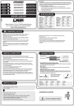
f43 speed controller series
schulze
not recommended in addition with SIMPROP System 90 transmitters
user manual
elektronik
gmbh
issue 9.2.97, page 1 of 4
Chaper Content
1 CE-Certification
2 Safety Precautions
3 General Warnings
4 Range of Applications
5 Characteristics
6 Monitoring and Safety Circuits
7 Adjustment
8 Control
9 Warranty
10 Installation Instructions
11 Technical Data
Page
1
1
1
2
2
3
3
3
3
4
4
1) CE-Certification:
The products described in this manual are manufactured in
accordance with all specific and mandatory European CE guidelines:
EMI 89/336/EEC, 91/263/EEC and 92/31/EEC.
The products have been tested according to these norms:
EMI-emissions:
EMI-resistance:
EN 50 081-1:1992
EN 50 082-1:1992 or EN 50 082-2:1995
Design and construction of our products comply with the requirements for safe operation.
EMI emissions were tested under realistic conditions, i.e. using
suitable motors and operating at 75% power settings, close to the
maximum allowed currents. Testing at full power and/or using
resistors instead of motors will not create maximum emission levels.
Further testing is done to ensure adequate EMI-resistance against
emissions from other devices. The HF signals used for these tests are
similar to those produced by mobile telephones or RC transmitters.
Again, our products are tested under realistic conditions for the
most dangerous situation: Exposed to the field of a powerful Tx, the
motor must not start while working on the model.
Problems using our products are most likely caused by
unsuitable combinations of radio components or improper
installations.
3) General Warnings:
Electric motors with propellers are dangerous objects which
require due care for safe operation. Keep away from the danger
zones when the battery-pack is connected.
The CE-Certificate on the speed controller is not a permit for
careless handling!
Technical defects of electrical or mechanical nature may result in
unintended motor runs and/or loose parts may cause serious personal injuries and/or property damage.
Every time you use your propulsion system - before turning
on the Rx -, make sure that:
a) no one else is using the same frequency (identical channel
number)
b) your transmitter is turned on and the throttle stick is in STOP
position.
Also to be considered:
c) Electronic equipment is sensitive to humidity. Speed controllers
which have got wet may not function properly even after thorough
drying.
d) Protect the speed controller against mechanical loads.
... your motor is suppressed by at least two, better: three, ceramic
capacitors of 10 ... 100nF / 63 ... 100V.
Extra suppression can also be achieved using filters with coils.
e) The f43 are not protected against reverse polarity (+ pole
changed with -pole) and connection of your battery pack to the
motor leads of the controller will almost certainly cause irreparable
damage.
f) Use only compatible connectors. A 2mm pin in a 2.5mm socket
will not provide reliable contact. The same applies for 2mm gold pins
in 2mm tin sockets.
... your receiver and its antenna are at least 3cm away from the
motor, the speed controller and the high current cables.
g) Regularly check the wiring of your RC-components for loose
wires, oxidation, or damaged insulation, especially when using BEC.
... all high current cables are as short as possible. Maximum length
between flight pack and speed controller: 20cm, between
speed controller and motor: 12cm.
h) The f43 are exclusively designed for RC-models. Their use in
man carrying aircraft is prohibited.
2) Safety Precautions:
Make sure that:
... all high current cables longer than 5cm are twisted, especially
the motor cables.
... half of the receiver antenna is routed along the fuselage (in a
boat above the waterline!) with the other half outside in a
vertical position. On an aircraft model part of the antenna
may hang down freely, but be careful not to step on it!
i) Never disconnect your flight pack while the motor is still
running. The speed controller may suffer damage.
j) Never leave your flight pack connected while the model is not
in use. Never charge it while connected to the speed controller.
k) Ensure that your electric motor is properly suppressed.
l) Check receiver performance via range tests (Tx-antenna
retracted, motor running in mid range). Speed controllers with BEC
are generally more sensitive to electromagnetic noise than those with
opto-couplers.
schulze elektronik gmbh • prenzlauer weg 6 • D-64331 weiterstadt • tel: 06150/1306-5, fax: 1306-99
internet: http://www.schulze-elektronik.com
e-mail: [email protected]
f43 speed controller series
not recommended in addition with SIMPROP System 90 transmitters
user manual
m) Usage in RC-Helicopters: Always disconnect the flight pack
before turning off the Rx. The still running gyro may provide
sufficient voltage and create unwanted signals to cause uncontrolled
motor runs.
n) Warning: The f43 content monitoring circuits. Their effectiveness depends on a fully functional speed controller. In case of a
short within the throttle transistor, neither the Stop signal from the
Tx nor the current limitation nor the temperature monitoring circuits
can stop the motor.
o) Note: Be reminded that the monitoring circuits can not detect
every abnormal condition. For example: Short circuits between
motor wires or operations above the nominal controller current limit.
As the maximum current of a cold f43 far exceeds the initial motor
current, a permanent current close to the peak value can not be
detected in older speed controllers without decreasing current
limitation. Current reduction due to a blocked air screw will only
occur if the motor current far exceeds the current limit value of the
speed controller, i.e.: A stall current of only 20A would not be
considered abnormal by an 80A controller.
p) Limits of Liability: As we can not control and ensure the
proper usage of our products, Schulze Electronic GmbH can not be
held liable for losses, damage or costs due to improper usage or
during incidents caused by the operation of radio-controlled models.
4) Range of Applications:
f43-125Fo is specially designed and optimized for FAI championships
F5B.
schulze
elektronik
gmbh
issue 9.2.97, page 2 of 4
5) Features:
Power-On Reset:
f43 controllers include a power on reset circuit.
Motor will not run while connecting the power battery pack, if
Tx throttle stick is at STOP position.
Soft Start Circuit:
f43 controllers include a soft start circuit. You can
activate f43 controllers from a switch instead of the normal
throttle stick.
Opto-Coupler:
By means of the build in optocoupler, the interference between
motor and receiver is minimized.
But: There is a need for a receiver battery.
LED Monitor:
LED helps to adjust and to indicate power settings.
Switching Frequency:
Switching frequency of 1.1 kHz is optimized for low power loss
and high efficiency.
EMF-brake (not f43-60Ho):
The brake is activated automatically when f43 is set to the
STOP position.
Brake is recommended when using folding props.
Shottky Diodes (f43-60Ho only):
By means of the shottky diodes, f43-60Ho works with highest
efficiency using half throttle.
Optimizing means:
Transistors:
Power mosfets of the latest technology are used for throttle and
brake circuit.
• Cause of its extremly low resistance FETs and its widely overdimensioned brake, it is well suited for all loads in 19 - 27 cell
contests.
Housing:
f43 controllers are suited in clear high temperature heat shrink
tube.
• For normal use and medium current, minimum cell number is 9
cells. For F5B/E (10 cell FAI application), the f43-120Fo is
recommended.
Cables:
All controllers are sold with highly flexible cables.
It can be used with direct driven props or gear-driven props.
• Soft start time is strongly reduced, f43 will react precisely (strict,
quick) to your throttle-stick or throttle switch.
• The heat sink (sheet metal) is a true protective part and thinner and
more lightweight than most other.
• The technical data of the f43-125Fo are made for the use in F5B
contests and therefore especially not designed for the use with half
throttle. The maximum uninterrupted motor-runtime of f43-120
and -125Fo with nominal current is approx. 15s. Then they have
to cool down (within the speed flight).
f43-120Fo is similar to the f43-125Fo, but specially designed for
F5B/E contests (10 cells), .
f43-60bo is a variant of the f43 with much power and strong brake
but increased soft start time;
this is the universal speed controller for all normal use.
f43-50bo is the economical variant for small and medium sized
models.
f43-60Ho is a variant for the use with half throttle and no brake,
specially designed for helicopter applications or acrobatic planes.
schulze elektronik gmbh • prenzlauer weg 6 • D-64331 weiterstadt • tel: 06150/1306-5, fax: 1306-99
internet: http://www.schulze-elektronik.com
e-mail: [email protected]
f43 speed controller series
not recommended in addition with SIMPROP System 90 transmitters
user manual
schulze
elektronik
gmbh
issue 9.2.97, page 3 of 4
6) Monitoring and Safety Circuits:
8) Control:
Current monitoring: Current monitoring will limit the current in
case of a stalled motor. Motors with current consumptions above
the specified current limit will not reach Full Power. The throttle
indicator LED will remain at half intensity. With a maximum
current exceeding 150A, a cold f43-120Fo or f43-125Fo will
most probably surpass the performance of the battery.
You can control the state of the f43 by observing light emitting
diode (LED). The brightness of the LED is inverse proportional to the
voltage (= rotations) of the motor. If f43 is in overcurrent state, LED
will not extinguish.
Temperature monitoring: Temperature monitoring will stop the
motor.
caution: if f43 has cooled down, it will switch the
motor on again by itself if you have not moved the
throttle stick into stop position!
Note: In case there is a short circuit between the motor windings or
motor cables, the monitoring circuits may not act fast enough.
Immediately turn off the motor to avoid permanent damage to the
speed controller.
Low-voltage monitoring: This feature is not buildt in.
7) Adjustment:
7.1) Tx-Programming for Helicopters:
Steps to be followed before adjusting the f43 as described in next
chapter.
9) Warranty:
All f43 have been examined carefully before the delivery under
practice conditions with accumulators at the motor. If you should
have reason for the complaint, please send the device back to us with
a clear error description. The text "No 100% function" is not enough!
Test the f43 carefully once more before returning it. If our tests
show no problem with your device, you have to buy the costs of our
testing. It is insignificant, whether the device will be send back within
the time of warranty or later.
Hint: If you have a problem with a device of us, please send it
directly back to us without previously soldering in it. So the results
of repair are the fastest, the costs remain low and warranty errors
are recognized without doubt. Then you can be sure too, that only
original parts will be inserted (We have had to make already bad
experiences with alleged service stations). Cause of previously done
repair outside of our firm and/or by improper repair the costs of
repair can not longer be estimated, a repair of such devices is possibly
refused by us completely.
For a stationary hover an electric helicopter requires usually 7585% of available power.
As trim travels or settings on the transmitter are often limited, it is
recommended to offset the neutral position (hover position) by
changing the throttle end point adjustments to 150% (Power-Off)
and 50% (Full Power). This little trick will enable you to use the full
trim range for the final set-up.
7.2) f43 speed controller adjustment:
f43 is factory set-up to suit GRAUPNER mc-10 / mc-20 systems.
The stop point can be adjusted if necessary by rotating the trimpot on the f43.
The range direction and range widths between stop and full throttle
is fixed. if you will adjust, please use servo reverse and servo travel
facility in your transmitter.
Caution:
1) For safety, remove prop before adjusting f43. Do not use more
than 10 NiCd cells during adjusting procedure without prop.
2) If you use a hot 10 cell motor in combination with f43-120Fo,
adjusting procedure without prop must be done with 7 cells.
3) Braking transistors may overheat, if you should run and brake the
f43 several times within few seconds.
schulze elektronik gmbh • prenzlauer weg 6 • D-64331 weiterstadt • tel: 06150/1306-5, fax: 1306-99
internet: http://www.schulze-elektronik.com
e-mail: [email protected]
f43 speed controller series
schulze
not recommended in addition with SIMPROP System 90 transmitters
elektronik
gmbh
user manual
issue 9.2.97, page 4 of 4
10) Installation Instructions:
Using others than reverse polarity protected connectors will void your warranty. Suitable for up to 35A are Gold 2mm (with limitations),
Gold 2.5mm or the green MPX 6-pin systems. For higher currents 4mm systems like the Conzelmann CT4 may be used (available as
accessory).
Soldering instructions for f43 cables to 4mm (CT4) connectors:
f43 battery +: Feed red cable from the rear through the tighter red tube of the double housing, solder (female) socket and press it in*
f43 battery - : Feed black cable from the rear through the wider tube of the double housing, solder (male) pin and press it in*
f43 motor +: Feed red cable from the rear through the wider yellow tube of a split double housing**, solder pin and press it in*
f43 motor - : Feed black cable through the wider yellow tube of a split double housing**, solder pin and press it in*
Please use red housings on cables of accumulator pack and yellow housings on cables of your motor.
[*]
For correct installation of connectors we recommend to use a parallel vice and a hammer.
Damage to the socket during installation can be avoided by leaving a single pin inserted.
[**]
The cut-off tighter housing halves are used to insulate the sockets soldered to the motor cables.
If motors with integrated sockets are used, the leftover housing halves are replaced by yellow heat shrink tubing.
Whenever possible the motor should be directly soldered to the motor cables (red and yellow of the f43). Keep the length of
the cables short to reduce EMI emissions!
To change the direction of motor rotation simply swap the motor cables. Never reverse the battery cables!
Avoid excessive heat built-up by packing the f43 in foam rubber. Fix it with Velcro!
11) Technical Data
Range of voltage [V]
Number of Ni-Cd cells
Nominal- / peak-current [A]*
Nominal current at 9.6V (8 cells)
f43-50bo
9.6 - 28.8
8-24
50 / 65
35A-75s,
25A-240s.
Nominal current at 8,4V (7 cells)
35A-45s,
25A-120s.
FET resistance throttle/brake [mW]** 4 / 8
Voltage loss at 10A [mV]***
50
Cable cross section [mm2]
2.5
Weight without/with cables approx.[g] x/47
Dimensions approx. [mm]
44x34x11
Overheat limit approx. [°C]
Switching frequency approx. [kHz]
f43-60bo
f43-60Ho
f43-120Fo
f43-125Fo
10.8 - 36
9-30
60 / 85
45A-90s,
35A-120s.
45A-60s,
35A-90s.
3.2 / 5.3
35
2.5
x/55
44 x 34 x 11
10.8 - 36
9 - 30
60 / 85
45A-90s
35A-120s
45A-60s
35A-90s
3.2 / -.35
2.5
x/58
44(75)x34x11
110
1.1
8.4 - 14.4
7-14
120 / 140
10.8 - 36
9-30
125 / 150
not
permitted
not
permitted
1.6 / 2.7
28
4.0
x/61
44 x 34 x 11
2 / 3.3
28
4.0
x/61
44 x 34 x 11
f43 do not have any voltage doubler for the gate voltage of the power mosfets. In this case, the maximum load at low voltage decreased (see obove).
Please note the limitations by time too.
[*]
f43 can operate at full throttle and nominal current for the length of a 2000mAh battery charge.
The maximum uninterrupted motor-runtime of f43-120 and -125Fo with nominal current is approx. 15s. Then they have to cool down.
If using with a low number of cells or using with half throttle, the maximum of permissible current of the motor, measured at full power,
may be lower (50%) depending on the position of the throttle and/or the number of cells in use.
The value of the specificated peak current correspondents approximately to the threshold point of the current limiting circuit, varying with
temperature.
Peak current is higher when f43 is cold and could be lower than the specified value when it is warm/hot.
[**]
Data sheet values, varies with gate-voltage and temperature.
[***] Typical measured data at 13V input voltage, 30A load and 25°C temperature.
Measuring points nearest to f43 between pins in minus battery wire (- akku) and minus motor (- motor) wire.
schulze elektronik gmbh • prenzlauer weg 6 • D-64331 weiterstadt • tel: 06150/1306-5, fax: 1306-99
internet: http://www.schulze-elektronik.com
e-mail: [email protected]


