1
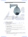
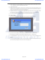
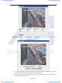
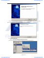
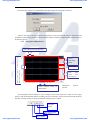
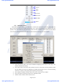
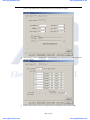
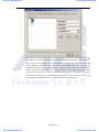
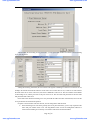
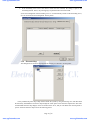
www.agelectronica.com www.agelectronica.com Honorific Users, please carefully read this system user manual before using this video server, as the functions of this machine are professionally set. Network Dome Camera PTZ-942L Network Instruction Manual www.agelectronica.com www.agelectronica.com www.agelectronica.com www.agelectronica.com Announcement This manual may not accurately describe on some technical details or contain some printing error. If you could not solve problems countered in the application process against the user manual, please call at our technology department for relevant operational methods. This manual is subject to nonscheduled change without further notice. Packing List 1. Network Dome Camera 1 Set 2. DC12V、4A Power Adapter 1PC 3. User Instruction Manual 1PC 4. Attached Compact Disk 1PC 5. Acceptance Certificate and Warrant Card 1PC Page 2 of 36 www.agelectronica.com www.agelectronica.com www.agelectronica.com www.agelectronica.com Contents 1 Product Introduction .................................................................................. ¡Error! Marcador no definido. 1.1 Product Introduction .............................................................................. ¡Error! Marcador no definido. 1.2 Function Introduction............................................................................. ¡Error! Marcador no definido. 1.3 Technical Specification ........................................................................... ¡Error! Marcador no definido. 2 Appearacne and Description...................................................................... ¡Error! Marcador no definido. 3 Equipment and Installation........................................................................ ¡Error! Marcador no definido. 3.1 Operating Conditions ............................................................................. ¡Error! Marcador no definido. 3.2 Equipment Instalaltion ........................................................................... ¡Error! Marcador no definido. 4 IE Version Client Side...................................................................................................................................6 4.1 Set-Up Service ......................................................................................... ¡Error! Marcador no definido. 4.2 Start to Login........................................................................................... ¡Error! Marcador no definido. 4.3 Function Introduction............................................................................. ¡Error! Marcador no definido. 5 RealWorld Client-Side Centralized Management Software....................................................................18 5.1 Brief Introduction ................................................................................... ¡Error! Marcador no definido. 5.2 Software Installation............................................................................... ¡Error! Marcador no definido. 5.3 Function Operation................................................................................. ¡Error! Marcador no definido. 5.3.1 Start-Up Network Monitoring Management Software .................... ¡Error! Marcador no definido. 5.3.2 Description of Main Interface ............................................................ ¡Error! Marcador no definido. 5.3.3 Distribute Video Camera .................................................................... ¡Error! Marcador no definido. 5.3.4 Video Camera Setup ........................................................................... ¡Error! Marcador no definido. 5.3.5 System Setup........................................................................................ ¡Error! Marcador no definido. 5.3.6 Electronic Map .................................................................................... ¡Error! Marcador no definido. 5.3.7 Video Playback .................................................................................... ¡Error! Marcador no definido. 6 Updating Software ...................................................................................... ¡Error! Marcador no definido. 7 Load Default Settings.................................................................................. ¡Error! Marcador no definido. 8 Frequent Asked Questions.......................................................................... ¡Error! Marcador no definido. 8.1 Fail to Access the Video Server through the Browser? ...................... ¡Error! Marcador no definido. 8.2 Cradle Head or Dome Camera Can Not be Controlled? .....................................................................32 8.3 After Program Updating, Video Couldn’t be Played Normally ..........................................................32 8.4 Fail to Browse Images Normally on Windows98.................................. ¡Error! Marcador no definido. 8.5 Only Sound but not Image When Video Files is Played on PC ........... ¡Error! Marcador no definido. 8.6 How to Use the Server to Carry on Video Transmission Service on Internet¡Error! Marcador no definido. 8.7 Why Do the Normal Data Fail to Pass Through the Exchanger ......... ¡Error! Marcador no definido. 8.8 Why Do Errors Occur When Accessing the Video Server through the Browser after Updating? ¡Error! Marcador no definido. 8.9 The Video Effect is not Good?................................................................ ¡Error! Marcador no definido. 9 Appendix ...................................................................................................... ¡Error! Marcador no definido. Appendix A Problem Description on Video Server Port Occupation (Mapping)¡Error! Marcador no definido. Appendix B Application Method Description on Dynamic Domain Name Service¡Error! Marcador no definido. Appendix C Description on Alarm Input and Output Connection Method¡Error! Marcador no definido. Page 3 of 36 www.agelectronica.com www.agelectronica.com www.agelectronica.com www.agelectronica.com Page 4 of 36 www.agelectronica.com www.agelectronica.com www.agelectronica.com 1 www.agelectronica.com Product Introduction 1.1 Product Introduction Thanks for using our product and we’ll provide you with the best service. The network video server is the equipment dedicated for real-time transmission of digital video and audio in Ethernet. Adopting the programmable high-speed digital signal processor (DSP) specially designed for multi-media processing, the network video server, which combines high-performance operation system and audio-video compression algorithm, makes the image transmission more fluent and display more clear and smooth; in addition, including the built-in WEB server, it can enhance the performance of traditional monitoring system, and provide the network connectivity for issuing the monitoring images on a safe local area network or internet. The management, configuration, monitoring and other functions of video camera can be operated easily through the Internet Explore. 1.2 Function Introduction ¾ ¾ ¾ ¾ Standard MPEG-4 Video Compression Format Standard MP3 Audio Compression Format Support D1, HALF-D1 and CIF Formats With the built-in Web Server, it fully supports IE monitoring, configuration and updating, so that it is characterized by simple and convenient operation The dynamic rate control assures the real-time transmission of audio on Internet Bidirectional Voice Talkback User management supports the three-level password Alarm input and output can support mobile sensing, date, time, and event trigger. Support local video (files can be directly played by Microsoft MediaPlayer and no other software installation is required). Support image mask ¾ ¾ ¾ ¾ ¾ ¾ ¾ Support image capturing 1.3 Network PCB Technical Specification Video Standard Support NTSC or PAL Format Video Mode MPEG-4 Four-Channel Independent Coding Compression Frame Rate 50 Frame/Second(PAL Format) ,60 Frame/Second(NTSC Format) Adjustable Downwards Audio Standard Compression ISO-MPEG Audio Layer-3 Video Coding Size D1: 704×576 Optimal and Compatible Half D1: 704×288 CIF: 352×288 Video Bandwidth Average 200 kbps (Resolution 52×288 and 25 Frames per channel) Stream Usage Image Lag Less than 200 millisecond (LAN) Image Adjustment Adjustment for Brightness, Contrast, Chroma, Saturation, and Image Quality Level Supported Resolution PAL: 704×576, 704×288 and 352×288 NTSC: 704×480, 704×240 and 352×240 Performance Output Frame Rate is 30fps at most and Network Bandwidth Usage is 32Kbps at least Page 5 of 36 www.agelectronica.com www.agelectronica.com www.agelectronica.com Trigger Action www.agelectronica.com Event Recommended Supported Quantity IO and Interface and Trigger Conditions: Time/Alarm Input/Video Moving Detecting Video Lost Action: Electrical Relay Output Control Peripheral Equipment 10 User Control 485Transparent Channel Embedded Type WEB Service Support IE Browsing, Configuration and Updating Dynamic Domain Name Built-in Dynamic Domain Name Client Side and Second-Level Domain Name Convenient for Dynamic IP Users Video Input 1/2/4 Way 1.0V(P-P), 75Ω Composite, BNC, and PAL/NTSC(relating to model) Audio Input 1/2/4 Way BNC Interface, Microphone Input or Linear Input (relating to model) Audio Output 1.0V(P-P) BNC Interface and Linear Output Hardware CPU: High-Performance DSP Processor Operation System: Real-Time Embedded Type VxWorks Operation System ROM: 4M Bytes Flash ROM RAM: 64M Bytes SDRAM Watch Dog: Apply to Program Execution of Voltage Normal of Monitoring System One S-485Port One RJ-45 User Ethernet Interface Two Led Display Network State 2/4 Alarm Input (Adopt Threshold Voltage 3.1-4.1) (relating to model) 1/4 Electrical Relay Alarm Output (1A 120VAC 1A 24VDC) (relating to model) Network Interface 10/100M Installation None System Requirements CPU: P or Higher Internal Memory: 96M or Higher Display: 17inch@1024×768 for Optimal Display Effect Security 3-Layer Password Protection Operating Temperature 5 ~ 60 Operating Humidity 20 ~ 80% Output Voltage DC12V /1A Power Less than 5Watt PCB Dimension 110mm(W) * 70mm(H)*2mm(D)(1/2 Channel) 157mm(W) * 115mm(H)*2mm(D)(4 Channel) Installed Dimension 205mm(W)*122mm(H)*48mm(D) Page 6 of 36 www.agelectronica.com www.agelectronica.com www.agelectronica.com 2 3 www.agelectronica.com Appearance and Description ¾ ¾ ¾ ¾ Power Input: DC12V and 4A FourServer Interface Audio Output Interface: Line Level, Disequilibrium, Single Track andChannel RCA Interface Audio Input Interface 1: Microphone Input, Disequilibrium, Single Track and RCA Interface Video Input Interface 1: 220x Sony CCD Camera ¾ International protect level:IP66 Equipment and Installation 3.1 Operating Conditions Operation System: Windows2000server/professional/XP Network Protocol: TCP/IP Client PC: P4/128MRAM/40GHD/, and Scaling-Supported Graphic Card and DirectX8.0 Above 3.2 a. b. c. d. 4 Equipment Installation Connect the video server into your network or use the cross twine to connect the video server to the PC. Connect the standard 75Ω coaxial-cable to the BNC video input port of the video server. Switch on Power (DC 12V) Under the normal condition, the connection light (orange) of network will light on within 5 seconds, and the physical connection of the video server is finished at this point. IE Version Client Side 4.1 1) Set-Up Service IP address of each video server is defaulted as 169.254.178.251 and subnet mask is defaulted as 255.255.0.0. Please make the IP address of your computer into the same net section as the video server, and be same with the subnet mask, such as 169.254.178.55. Page 7 of 36 www.agelectronica.com www.agelectronica.com www.agelectronica.com 2) 3) 4) 5) 6) 4.2 www.agelectronica.com Test the video server is start up normally or not. Under the Windows System, operate against the <Start →run →command> to open the command window to input <ping 169.254.178.251> When using the Internet Explore at the first time, you must lower the security setting casually so as to install the ActiveX components to the network at one time, and then select the Tool Æ Internet Options Æ Security Æ Customize LevelÆ ActiveX Control and Plug-In> Setup the security level as low and click the Apply button. Input 169.254.178.251 at the explore address field. If pop up a dialogue box to ask if you want to install, please click Yes to start the installation. Once ActiveX installation is finished, the security setting will load the default value. Start to Login 1) Input 169.254.178.251 into the address filed and then login page will appear as follows. 2) 3) Input the user name: 888888 (ex-factory default and administrator user) or 1 (common user) Input the password: 888888 ex-factory default and administrator user) or 1 (common user) 4) Click 【Enter】button to enter into the preview picture of video server, as shown in following picture 5) (4-Way) You can click [start] and [stop] to stop or reset the connection. During the connection process, the type style of connecting will appear on the top left corner of the display area. Page 8 of 36 www.agelectronica.com www.agelectronica.com www.agelectronica.com 4.3 www.agelectronica.com Function Introduction 【Network Mode】: TCP and MultiCast can be selected according to your demand. Note: please select again after the page is switched. 【Channel Select】: Click the image window to make the selected image window be the current operational channel. The numbers of channels are respectively channel 1: top left; channel 2. top right; channel 3: low left; and channel 4: low right in turn. 【Start-up】: After entering into preview interface, the 4-way channel image will automatically connect. You button to open or close the image of some channel can click independently. 【Preview Start】: Click 【Preview End】: Click to connect images of all channels at the same time. to stop images of all channels. The connection state of current channel can be known through the state of buttons. 【Image Capture】: Click this button to save the current screen image and store it under the temp directory of C disk. 【Audio】: Click the audio button to open the audio connected to the current channel, and the state of button will change into green. When switching to other channel, the audio will be also switched to this channel. 【Talkback】: Click the talkback button to startup the talkback and the state of button will change into green. Click the button again to stop talkback. 【Video Recording】: Select the channel to be recorded and then click the button. Till the state of button Page 9 of 36 www.agelectronica.com www.agelectronica.com www.agelectronica.com www.agelectronica.com change into green, the system will start video recording. Click the button again to stop video recording. The video recorded is defaulted to be stored in the folder named as date in D disk. For example, the video file recorded on 24th, March, 2005 is saved in 20050324 folder. If the space of D disk is full, the system will automatically switch to next disk to save the video files. If no enough space in disk, the earliest files will be deleted and the newest files will be saved. 【Playback】: Click this button to display the playback interface. Please select the date and time to click the arrow, the system will automatically inquire about the existing video recording. Click the file to play it directly by using the MediaPlayer. 【Output Control】: 4 output state control buttons can control 4 small signal electrical relays on the video server, and show the state of electrical relay through the colour state. 【Image Size】: The size of image display can be selected and the maximum size is the full-screen display. 【Lens Control】: Click the buttons on 4 directions to control the moving direction of cradle head; click and to control the focus of camera lens. In addition, select the speed stretch bar to confirm the moving speed of cradle head. 【Parameter Setting】: The system settings include time setup, network setup, channel setup, and image setup which are shown as right pictures. 【Clock Adjustment】: The clock of network camera can be adjusted to display on the real-time image with the connected computer. 【Audio Format】: The compression algorithm supports MP3 only at present. The code rate of audio can be selected. If the code rate is low, the bandwidth usage will be decreased, but the sound effect will be worse. Therefore, if bandwidth permit, the higher the code rate is, the better the sound effect is. Page 10 of 36 www.agelectronica.com www.agelectronica.com www.agelectronica.com www.agelectronica.com 【Video Format】: You can select it as PAL or NTSC 【Network Address and Port】: IP Address, Subnet Mask, Gateway, Multicast Address, Multicast Port Number, and ICMP Response are the network data of video server. If apply at the local area network, please take notice that don’t set the IP address collide with the IP address of computers located at the local area network. Modifying the web address can change the browser access port provided by the WebServer of video server, and modifying the data transmission port can change the audio port occupied by video server during the network transmission (for details of port occupation, please refer to appendix A) 【MAC Address】: MAC address is the network hardware address of the equipment. Please don’t modify it at will unless required. Page 11 of 36 www.agelectronica.com www.agelectronica.com www.agelectronica.com www.agelectronica.com 【Dynamic Domain Name】: ¾ Start up URL forwarding: As the IP address is not convenient to be memorized, you can register the domain name to get rid of annoyance of inputting the IP address. ¾ Register Host Name: mean that you can register the domain name you like. This name must be registered on the dynamic domain name server, otherwise it won’t be used normally. ¾ DNS Server Address: Run the host address of the domain name service program. ¾ DNS Server Port: The monitoring port of domain name service program. ¾ Local Mapping Port: Refer to the pointing of WEB port when the video server carrying on the port mapping in the internal network. This port shall keep in line with the defaulted 80 port in port mapping program. (For the operating instruction of the dynamic domain name server program, please refer to Appendix B) 【Display Control and Channel Protocol】: Page 12 of 36 www.agelectronica.com www.agelectronica.com www.agelectronica.com ¾ ¾ ¾ www.agelectronica.com Character Superimposition: You can select the character content and display time to superpose on the image. The position of display character and time on the image can be also adjusted and the position coordinates on top left of image is (0, 0). Cradle Head Protocol: The selected protocol, baud rate, and address must be accordant with the protocol, baud rate and address of the selected cradle head or dome camera. Otherwise, the cradle head or dome camera may be out of control. Detection and Backup: You can set the duration of alarm signal produced by triggering the GPIO. This setting is used to detect the video signal is lost or not. If lost, the alarm system will be triggered. 【Image Quality Control】: Page 13 of 36 www.agelectronica.com www.agelectronica.com www.agelectronica.com ¾ ¾ ¾ ¾ www.agelectronica.com Code Rate Setup: Mean that the compression input code rate of the video server can be setup according to the network bandwidth. The higher the code rate is, the better the image quality. However, the occupied bandwidth will increase as well. Please adjust the setting according to your actual bandwidth situation. It’s recommended that the quantized setup ranges from the maximum quantized value of 31 to the minimum quantized value of 4. Quality Setup: Mean that the code rate of the video server is not restricted. The quality of image is determined by the quantizing coefficient. The smaller the quantizing coefficient is, the refiner the image quality is. However, the minimum setting shall be 4. Frame Rate Control: When the network condition is not ideal, adopt the method of decreasing the frame per second to reach more smooth and fluent effect of moving images. Maximize Quantizing Coefficient: When the network condition is not good, the system will automatically adjust the quantizing coefficient of coding to decrease the data size of image coding. When reaching the limit value, if the network environment still fails to reach the requirement, the coder will decrease the frame rate to control the image continuity to reach the optimal visual effect. No matter selecting the quality coding or rate coding, above parameters are relevant to each other. For example, when acting as the coding for quality setup, the values of code rate parameter in the code rate setup will become the maximum coding rate used by quality setup coding. 【Colour Adjustment】: The brightness, contrast, saturation and chroma of the channel can be adjusted as required. Page 14 of 36 www.agelectronica.com www.agelectronica.com www.agelectronica.com www.agelectronica.com 【Moving Detection】: It can detect whether the mobile objects exist in current images. If alarm output is set, the mobile object will trigger the alarm. ¾ ¾ Sensitivity Adjustment: the setting of adjusting the detecting sensitivity. Under the high-sensitivity setting, the object moving at slow speed will also trigger the alarm. Test Switch: Open this switch to test that the sensitivity you set is appropriate or not. If it triggers, grey block will flash in the triggered area. Page 15 of 36 www.agelectronica.com www.agelectronica.com www.agelectronica.com ¾ ¾ ¾ www.agelectronica.com Select All: Set the whole image as the detecting area. Delete All: Delete the set area. Confirm: Save the current setting. 【Image Mask】: 【Moving Detection Planning】: ¾ The video server supports the selection for many kinds of alarm methods and implementation time, and the arrangement of all kinds of plan tasks is set at the “detection planning”. The detection planning can be designed as the project of various complex monitoring starting and closing. Page 16 of 36 www.agelectronica.com www.agelectronica.com www.agelectronica.com ¾ www.agelectronica.com No matter the moving detection or the external alarm detection, there is a plan task list. In accordance with the setting in this list, the video server will start or stop alarm. The plan task consists of 7 groups of settings totally, and each group includes the date, starting time and ending time. The first row on the left is optional for date。 During this row, each group contains Monday, Tuesday, Wednesday, Thursday, ¾ ¾ Friday, Saturday, Sunday, Monday to Friday, Saturday to Sunday, Everyday, and Close, totally 11 kinds of selections. The two rows behind the data selection refer to the setting of starting time and ending time. During the moving alarm, the parameters for setting the alarm area and adjusting the alarm sensitivity are very important. Inappropriate parameters easily cause the false alarm or failure to alarm in case of alarm situation. The external alarm is dependent on the alarm signal triggered by the external inductor, such as infrared alarm unit. When the moving detection is started, the server will detect the moving objects within the alarm area during the arranged planning date and time, and link the video recording or alarm output according to the setting below. 【Probe Alarm】: When starting the probe detection, the video server will receive the message from the ¾ ¾ ¾ external inductor, and link the vide recording or alarm output according to the set triggering below. Arrange Plan: totally 7 groups of time arrange the plans in different time intervals. Link Video Recording: Make video recording when alarm triggering exist. Start Alarm Output: When alarm exists, the external alarm output will be started to trigger the externally-connected alarm unit. (For the detailed alarm input and output connection, please refer to Appendix C) 【System Updating】: Select the itm file to be updated and update the program within the equipment for yourself. Page 17 of 36 www.agelectronica.com www.agelectronica.com www.agelectronica.com www.agelectronica.com 【Setting Save and Restore】: Save the current settings or load the default setting. 【User Information】: Support the password supervisor privilege and only administrator can modify the parameters. Page 18 of 36 www.agelectronica.com www.agelectronica.com www.agelectronica.com 5 www.agelectronica.com RealWorld Client-Side Centralized Management Software 5.1 Brief Introduction The network monitoring management software adopts the distributed type system framework and C/S system structure, based on TCP/IP network platform. Currently, this monitoring management software can manage 80-way channels and support the electronic map. In addition to concise interface and convenient operation, it also owns preview, inquiry, video recording, alarm playback and many other functions. 5.2 Software Installation Operating Conditions Operation System: Windows2000server/professinal/XP Network Protocol: TCP/IP Client-Side PC: P4/128MRAM/40GHD/ Scaling-Supported Graphic Card and DirectX8.0 Above Installation Guide Open the folder of management software to run (double click the left key of mouse) the installation program file of RealWorld nDVR.exe, and the dialogue box will appear as follows: Page 19 of 36 www.agelectronica.com www.agelectronica.com www.agelectronica.com www.agelectronica.com And then carry on the installation according to the prompt of installation tool till the steps shown in following picture appear, and select the [Finish] button to install the program successfully. 5.3 Function Operation 5.3.1 Start Network Monitoring Management Software Select the program group for installation in the [Start] menu, shown as following picture. Page 20 of 36 www.agelectronica.com www.agelectronica.com www.agelectronica.com www.agelectronica.com Run the left key of mouse to click [RealWorld NDVR] to display the dialogue box as follows. Input the user name in the user name filed, and password in the password filed (The user name after initial installation is admin and the password is blank), and then click the [Confirm] to display the main interface shown in the following picture. 5.3.2 Description of Main Interface Connect: Multi-Image Switch Alarm Output Image Under Starting State Display Image Window: Multi-Channel Real-Time Control: Multi-Way Image Switching Cradle Head: Camera Probe Control Function Control: Parameter Setting and Channel Alarm Management Interface Software The management software displays 16 ways of images at most in the single screen, which can edit 5 pages totally, so that the management software can manage 80 ways of channels. You can poll each connected channel by manually switching the page or setting the automatic switching page as required. Automatic Switch Select Page Number Page 21 of 36 Page Number www.agelectronica.com www.agelectronica.com www.agelectronica.com www.agelectronica.com Description of bottom tool buttons: Camera Distribute Camera User Login Window Style System Log Lock System Playback Setting Edit E- Map System SettingOpen/Close E-Map Clear Ala 【User Login】: You can set password or set no password when starting the video server. 【Distribute Camera】: Click the button to call out the dialogue box of distributing camera. Clicking the button is equal to click the right key in the channel display area to select the camera distribution. The currently-selected channel will become the defaulted channel in the dialogue box of camera distribution. 【System Log】: The system log saves the state information, application program starting and operation and other information of the server. 【Window Style】: The camera description and other relevant information are displayed under the bottom of image or not. 【Playback】: Search all the video files and playback the relevant results as required. 【Lock System】: Click this button and then the system will enter into the state requiring the user name and password. In addition, no function can be operated. However, any relevant settings, such as alarm video, will not be locked. 【System Setting】: Local settings, including the video file processing, user management, data forwarding, etc. 【Camera Setting】: Click this button to call out the dialogue box of server setting. All the parameter settings in the video server can be set up here. If you login the video server through the identity other than administrator identity, no permission for setting server parameters is allowed to open this dialogue box. This button is equal to clicking the right key to select the camera setting in the channel display area. 【Open/Close Electronic Map】: Switch into the electronic map or return to the main control image. 【Edit Electronic Map】: Edit the created electronic map. 【Delete Alarm】: Delete the alarm sound, and others Description of right-side tool buttons Page 22 of 36 www.agelectronica.com www.agelectronica.com www.agelectronica.com www.agelectronica.com Multi-Image Control Full-Screen Display Connection Control Image Capturing Audio/Talkback 【Multi-Image Control】: 1 Image, 4-Image, 9-Image and 16-Image are optional 【Full-Screen Display】: Video image screen maximization 【Connection Control】: Start or stop the video connection of all current distributed camera image. In the 16-image format, the page-up and page-down button take no effect. Click the start button to connect all set channel images, and click the stop button to stop all connected images. If connecting certain image or disconnecting certain image separately is required, please click the right key to select the connecting or disconnecting in this image. 【Image Capture】: Capture the instantaneous image of the current channel 【Audio Play and Talkback Control】: Start or stop playing the audio and talkback of current channel 【Alarm Output/link】: The signal of alarm output state. If the alarm output relay attracts, the output signal will light on. Also, clicking this light to light it on will open the alarm output as well. See the picture. Alarm Output Link Button Control Button of Cradle Head Page 23 of 36 www.agelectronica.com www.agelectronica.com www.agelectronica.com www.agelectronica.com Aperture Focus Zoom Preset Point Assistant Switc Cradle Head Speed 5.3.3 Distribute Camera Before distributing the cameras, if the video server is located at the same local area network, please make sure that your IP network section is accordant with the video server. Select the [Distribute Camera] button or click the right key in the video channel to popup the menu to select the camera distribution. The currently-selected channel will become the defaulted channel in the called-out camera distribution dialogue box. See the picture: ¾ ¾ ¾ ¾ ¾ Camera Description: Refer to the camera information displaying on the bottom of this image. This content is the optional for filling. Server Name: Refer to the name of the connected video server. This name is the only identifier within the same domain and used as the identifying for dynamic domain name service or for the forwarding connection. So please avoid repeating when registering and connecting. Server Address: IP address or domain name can be used to connect the server address. Server Port: Refer to the data port of the server. Defaulted as 3000. Channel: Camera channel, which counts from zero. Page 24 of 36 www.agelectronica.com www.agelectronica.com www.agelectronica.com www.agelectronica.com ¾ Use DDNS: DDNS is the DDNS client side embedded by the video server. It works together with the DDNS server side provided by the developer. When using the DDNS function, the server name is the signal for searching this server. If the server name is incorrectly filled, the error information of failing to find the server will be returned. ¾ Automatic Connection on Starting: After the software is started, whether connect all the distributed cameras automatically. After filling above information in, please press the [confirm] button to exit the setup interface, and the system will automatically connect the distributed servers and play the video. If you want to delete a certain set distribution, please clear the description, name, address, port and other contents. 5.3.4 Camera Setting Camera setting consists of the server, channel, cradle head, alarm and others. 1) Server Setting: It mainly includes the equipment network setting, user password management, dynamic domain name system, multicast and other functions. Multicast is the optimal approach for solving the problem that a great many of clients visiting a same video server at the same time. However, please take notice that if you want to realize the multicast in the wide area network, some routers don’t support this function or have not started this function. See the picture. Note: After modifying the network parameters of the server, you must reset the server. 2) Channel Setting: this page of parameters set the parameters, channel alarm modes and date setting of all the coders relating to the channel. See the picture. Page 25 of 36 www.agelectronica.com www.agelectronica.com www.agelectronica.com ¾ ¾ ¾ www.agelectronica.com Select Channel: In case of many channels, the users can select the channel to be set as required. Code Stream Type: Composite Stream and Video Stream. The composite stream refers to the composite coding of the audio and video. This selection allows transmission of both audio and video; if the video stream is selected, only video but no audio is transmitted. Resolution: Refer to the original size of the compressed image, which consists of CIF(352×288), 2CIF (704×288)and 4CIF(704×576). 2CIF is also called Half D1 and 4 CIF is also called Full D1. Some ¾ ¾ ¾ ¾ ¾ ¾ ¾ ¾ products of our company support these three formats, but some only support CIF format. Please distinguish in the technical parameters of relevant products. Meanwhile, if you modify the resolution, you must save the configuration and then reset the video server. Otherwise, the modification will not take effect. Display Code Rate Information: If you select to display the code rate information, the video code rate of the current equipment will be dynamically displayed on the image screen. Variable Code Rate and Constant Code Rate: The variable code rate refers to only considering the image quality but not the size of code rate during the coding process at the cost of code rate; the constant code rate refers to decrease the image quality properly at some times (such as image actions are drastic) according to the code rate limit set by users at the cost of definition resolution. The quality coefficient ranges from 4 to 31. It’s recommended that please select the constant code rate at 4 if the bandwidth is sufficient. If the bandwidth is limited, please set the code rate according to the actual bandwidth. Alarm Delay: It is set that when alarm occurring, the duration of the alarm output sound Time Display: The format and reference of time display Detect Video Lost: When no video signal input, the alarm is started. Moving Detection: Set the detection conditions according to the area setting and detection time buttons. Image Parameter: Set the brightness, contrast, grey degree, and saturation to enable the image to reach the most appropriate color effect. 3) Cradle Head Setting: Set the cradle head control serial-port parameters and update the cradle head Page 26 of 36 www.agelectronica.com www.agelectronica.com www.agelectronica.com www.agelectronica.com protocol. The updating file of cradle head protocol is provided by the supplier. 4) Alarm Setting: Open or close the alarm and set the alarm time and link video recording and preset point as required. 5) Others: Set the starting of alarm screening and the time and linkage video of alarm linkage. Page 27 of 36 www.agelectronica.com www.agelectronica.com www.agelectronica.com www.agelectronica.com 5.3.5 System Setting The system setting is composed of the system parameter, system user, forwarding service setting and user management. 1) System Parameter: Alarm sounds of different channels, file packing length, log saving directory and others can be set up. 2) System User: User name, password and other information can be added and modified. Page 28 of 36 www.agelectronica.com www.agelectronica.com www.agelectronica.com www.agelectronica.com 3) Forwarding Server Setting: The video server management software contains the function of data forwarding. If you want to open the video signal for forwarding some channel, please select the option of [start the forwarding server]. The parameters of the forwarding server all refer to the address parameters of the server which is located by this management software. Of which, the channel user quantity refers to the maximum user quantity allowed for connecting by this channel, and the system user quantity refers to the quantity of total users who connect to this server. After these several parameters are set up, this management software shall be closed and then reopened. Otherwise, the setting will not take effect. What shall be noticed is that please don’t conflict with other programs when setting the local port and multicast address. See the picture. Page 29 of 36 www.agelectronica.com www.agelectronica.com www.agelectronica.com www.agelectronica.com After finishing the forwarding service port setting, you can open other machine to connect to the forwarding server. See the picture. Among the necessary parameters, the server name is the sign for confirming to connect to a certain server. For example, this channel forwards the channel 0 of the video server whose name is 123, so this server name must be the name of this server. In the video server, this name is defaulted as video server. The server address is the address of forwarding server, and the port refers to the port of the server. The user name and password are the user name and password of the video server. Please take notice that the forwarding server only forwards the audio and video of the channel, but not set the server parameters and use the PTZ operation. If require to forward in the wide area network, several settings below shall be made: ¾ If the forwarding server runs at the gateway (the access point of Internet), you are only required to take notice that port conflict exists or not. The long-distance users can use the management software to connect this forwarding server directly in accordance with above-mentioned method. Page 30 of 36 www.agelectronica.com www.agelectronica.com www.agelectronica.com ¾ www.agelectronica.com If the forwarding server runs at the interior of the local area network, the setting is equal to the forwarding Internet. That is, the port mapping is required and then connection made. 4) The user management of the forwarding server: it can automatically refresh out the forwarding server, so as to convenient for user management. See the picture. 5.3.6 Electronic Map The management of electronic map supports the directory tree structure. See the picture. Firstly establish the plane map of bmp format outside the system by using the drawing tool. And then finish the elementary establishment of electronic map through the “add” option in the electronic map function. The name of established electronic map displays on the list window of the server, and you can double click the map name to open or switch the electronic map to show the following picture. Page 31 of 36 www.agelectronica.com www.agelectronica.com www.agelectronica.com www.agelectronica.com Add Alarm Unit Moving Function Add Camera Add Alarm Probe Establish several videotaping points, alarm probes and alarm units in the electronic map through the “edit” function in the elementarily-finished electronic map. Double click the videotaping points established in the electronic map to open the corresponding videotaping images, and double click the probe alarm icon by right ky to open and close the alarm output. The moving function key can move the map and the videotaping point icon established in the map in the state of editing the electronic map. However, in the general state, it only owns the function of moving the map. After establishing the electronic map, when certain way video alarms, this way of image will automatically pop up. 5.3.7 Video Playback It can finish the searching and playing the video files. See the picture. In order to accelerate the searching speed, this system software doesn’t support the user customizing the data storage place. 6 Updating Software You can find a web address on the product packing carton. Please visit this website and you will find the newest version of this product. You can contrast through the [display version], and if the newest version is issued, please download and then decompress. Finally, select this file to update the video server online through the browser. Page 32 of 36 www.agelectronica.com www.agelectronica.com www.agelectronica.com 7 www.agelectronica.com Restore to Default Setting Click the [Confirm Restore] in the browser to load the default setting. However, you must know the IP address of the video server firstly. If you forget the IP address, please press the “reset” button in the panel and then the video server will automatically reset. Its IP address is 169.254.178.251, subnet mask is 255.255.255.0 and gateway is 169.254.178.1. The super user name and password are 888888 and 888888, and the common user name and password are 1 and 1. 8 Frequent Asked Questions 8.1 Fail to Access the Video Server through the Browser? Possible Cause: The network is disconnected. Solution: Connect the PC into the network to test that the network access can work normally or not. Firstly clear the cable fault and the network fault caused by PC virus till the network is connected. Possible Cause: IP address is occupied by other equipment. Solution: Disconnect the video server and network, and then connect the video server to the PC separately. Also, reset the IP address according to appropriate recommended operations. Possible Cause: IP address is located at different subnets. Solution: Check the settings of the IP address of server, the subnet mask address and gateway. Possible Cause: Unknown Solution: Restore to the ex-factory default state by pressing the restore button behind the server. 8.2 Cradle Head or Dome Camera Can Not be Controlled Possible Cause: The cradle head protocol, baud rate and address are not accordant with those of the used cradle head or dome camera. Solution: Enter into the setting page to change the cradle head protocol, baud rate and address into those of used cradle head. Possible Cause: The signal wire is poor connected or incorrectly connected. Solution: Connect the control wire of cradle head or dome camera and server again. 8.3 After Program Updating, Video Couldn’t be Played Normally Solution: Close all the browser pages and search the NetClient.dll、NetViewX.cab、NetViewX.ocx file under the C:\ directory. Then, delete them and connect the video server through the browser again, and the video server will automatically appear on the new play plug-in. 8.4 Fail to Browse Images Normally on Windows98 Solution: Install the DirecteX8.0 or higher version. Update IE Explore to 5.5 Version above. 6.0 Version is recommended. 8.5 Only Sound but not Image When Video Files is Played on PC Solution: Download and install the divx general encoder. 8.6 How to Use the Server to Carry on Video Transmission Service on Public Network (Internet) If you want to make the server transmit the data on Internet, you must know your network access mode firstly. If the public network owns the static IP address, you should set the IP address, subnet mask and gateway as the static address provided by ISP directly, otherwise, you won’t browse normally. In addition, the most widely-applied network access, respectively are ADSL and district board band, both require the certification process. The certification can be finished through some intelligent equipment, such as P or small-sized router. If located at the interiority of the local area network, the IP address of the public network will be set, so that the Page 33 of 36 www.agelectronica.com www.agelectronica.com www.agelectronica.com www.agelectronica.com external network will not see the interiority of the local area network. In this case, some settings shall be done on the connected server. Solution: ¾ If used at the local area network located at the office and building, but still want to visit this video server in other cities, you can make the forwarding by taking advantage of the machine accessing into the Internet. Concretely speaking, you can use the port mapping to finish forwarding the information packet. For the popular port mapping software, only simply setting is required, such as Portmap and portunnel. Select all the IP among the visited IP addresses, and then fill the address of the video server located at the local area network as the end IP address. ¾ In case of no PC, selecting the router as the forwarding equipment is also a good solution. At present, most routers own the function of port mapping, or also called DMZ. Appoint the DMZ address as the address fro the video address. ¾ Set a VPN server as the server of virtual privacy network, and then dial up at the long-distance client side. After connecting well, it can visit the internal host. 8.7 Why Do the Normal Data Fail to Pass Through the Exchanger? Possible Cause: 1. In case of the layer 2 exchanger, the address is wrongly written. 2. In case of layer 3 exchanger, the port and physical address binding is done or not. 3. When arranging the firewall rules, whether the server is considered. Solution: ¾ Before searching the network fault, please be sure to use the ping command in the command mode to connect the address of the other party. Viewing the message returned after ping is a very important ring. If no message is returned, it indicates that some faults exist in the network. ¾ If the IP address and Mac address are bind, adding a new binding of IP address and Mac address of the video server within the exchanger is required. ¾ If the server has not been considered when exchanger arranging the firewall rules, it’s necessary to allow the communication on 3000, 3001, 3002, 3003 and 80 ports for the server. 8.8 Why Do Errors Occur When Accessing the Video Server through the Browser after Updating? Delete the buffer memory of the browser. The detailed steps are as follows: open the tool menu of the browser to open the Internet option, and then click the “Delete File” button in the second item (temporary file of Internet) and check the “Delete All Offline Contents” option. And then confirm it, and finally login the server again. 8.9 The Video Effect is not Good? In case of many noises and serious distortion, please check that the input signal level is line input or not. At most times, if the input signal is not line input (such as with amplified active microphone), it may not match with the input level of the server, so that cause the saturation and distortion. Solution: Adopt the proper input (switching to MIC and LINE for option) according to the acceptable range of this video server. Page 34 of 36 www.agelectronica.com www.agelectronica.com www.agelectronica.com 9 www.agelectronica.com Appendix Appendix A Problem Description on Video Server Port Occupation (Mapping) This video server occupies the following ports when carrying on the video transmission service on the Internet: TCP: 80, 3000 and 3001 If one IP address exit owns several video servers, corresponding ports of the server must be modified as required, such as Web and data transmission starting port, plus 1 on the basic address sequence. UDP transmission port is 3002. Multicast port is port number plus channel *2. Appendix B Application Method Description on Dynamic Domain Name Service Adopt the second-level domain name mode to apply the system requirements of the dynamic domain name server: ¾ Access into the Internet independently and own the (fixed) IP address. ¾ DNS server resolves the domain name independently to this host. ¾ This independent domain name resolution owns wide domain name support (Make sure that any CNAME records are accurate and problem free.) 1) Run the dynamic domain name service software on this machine. 2) Once above conditions are met, lease open the browser to visit this dynamic domain name service software, and start the steps of host register. Under the default situation, if the service program doesn’t occupy the 80 port, please open /bin/sysfile.ini file to modify the port records in the [svrInfo] item, and then close this program. And then change the monitoring port of the service program. 3) After opening the host register page (see below picture), fill the information of the video server host in order. Expecting for the host name and description, the other information is automatically updated by the video server. So that the host name is unable to be changed after being registered successfully, unless delete this record. IP address here refers to the Internet IP address of the video server. As the video server is rarely separately connected to the Internet, this address is not the address set in the network setting of the video server generally. The mapping port refers to the defaulted port of HTTP and it is 80 generally. In addition, the data port refers to 3000. In case of the internal network port mapping, it is subject to the external mapping port. In the dynamic domain name setting page of the video server, please fill the relevant contents in: The host name is the registered corresponding host, and port number is the corresponding port (or mapping port). The host will update the host information on the domain name server according to these information. Page 35 of 36 www.agelectronica.com www.agelectronica.com www.agelectronica.com www.agelectronica.com Appendix C Description on Alarm Input and Output Connection Method The alarm input and alarm unit of the network video server generally own the 2 kinds of connection methods as follows: Alarm Output Connection Mode of the Network Video Server: A small signal electric relay (120VAC: 1A and AC120V: 1A) is built in the network video server to produce the switching signal. If need to control the high-voltage and large-current equipment, a intermediate relay shall be connected. Thanks for using this network video server. Owing to the differences Page 36 of 36 www.agelectronica.com www.agelectronica.com www.agelectronica.com www.agelectronica.com between each model or appearance or function differing from those described in this manual because of system software updating, please contact the manufacturer at any time. Please forgive that we could not inform you of these changes timely. Page 37 of 36 www.agelectronica.com www.agelectronica.com


![- [ [ [ ANSEL ] ] ]](http://vs1.manualzilla.com/store/data/005876018_1-a636cab6934c7a831e92a71c6eb2f063-150x150.png)