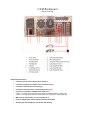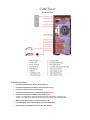
1
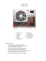
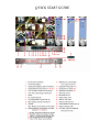
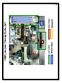
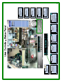
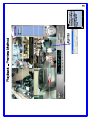
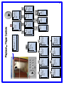
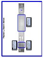
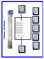
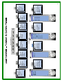
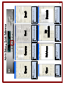
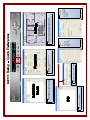
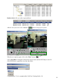
CAM LINE
USER TRAINING GUIDE
CAM Software v5.0
Includes…
1. CAM QUICK START GUIDES
2. CAM USER TRAINING GUIDE v5.0
3. WARRANTY INFORMATION
4. SOFTWARE CD AND RESTORE CD
Vision Controls Corporation
455 E. Industrial Drive
P.O. Box 94
Hartland, WI 53029
Technical Support: 262.369.8798
Sales & Service:
262.369.8797
eFAX: 312.602.1356 www.visioncontrols.net
Software CD Enclosed:
1. QUICK START GUIDES
a. Cube Chassis
b. MidTower Chassis
c. Rackmount Chassis
2. USER TRAINING GUIDE
3. REMOTE USER TRAINING GUIDE
4. COMPLETE USER MANUAL
5. 2007 WARRANTY INFORMATION
6.
SOFTWARE SETUP FILES
RESTORE DISK
This disk will reinstall all of the original software.
To use this disk insert it into the DVD drive and reboot PC.
Only use this disk…
• In the event of an OS drive failure.
Or
• The PC cannot boot into Windows.
Warning: Using this disk will completely erase everything currently on the OS drive.
(All video files on the storage drives will not be affected)
For any problems call Vision Controls support at 262-369-8798
CAM Rackmount
Hardware Setup
Quick Setup Instructions:
•
Connect the power cord to the AC power socket (1)
•
Connect the keyboard and mouse to the correct ports (3) (4)
•
Connect the ethernet cable if necessary (6)
•
Connect the monitor(s) to the corresponding port(s) (7) (9)
•
Connect the camera(s) to the BNC Camera Inputs (12)
Camera 1 is located in the lower left camera inputs are ordered bottom to top (SS only).
Camera 1 is located in the upper left camera inputs are ordered top to bottom (MP only).
•
Make sure the power switch is in the on position I (2)
•
Press the toggle power button located on the front of the DVR
•
All camera(s) should display on the monitor after booting
CAM Tower
Hardware Setup
Quick Setup Instructions:
•
Connect the power cord to the AC power socket (3)
•
Connect the keyboard and mouse to the correct ports (4) (5)
•
Connect the ethernet cable if necessary (8)
•
Connect the monitor(s) to the corresponding port(s) (10) (11)
•
Connect the camera(s) to the BNC Camera Inputs (13)
Camera 1 is located in the upper left camera inputs are ordered left to right (SS Only).
Camera 1 is located in the upper right camera inputs are ordered right to left (MP Only).
•
Make sure the power switch is in the on position I (2)
•
Press the toggle power button located on the front of the DVR
•
All camera(s) should display on the monitor after booting
CAM Cube
Hardware Setup
Quick Setup Instructions:
•
Connect the power cord to the AC power socket (1)
•
Connect the keyboard and mouse to the correct ports (2) (3)
•
Connect the ethernet cable if necessary (6)
•
Connect the monitor(s) to the corresponding port(s) (8) (9)
•
Connect the camera(s) to the BNC Camera Inputs (11)
Camera 1 is located in the lower left camera inputs are ordered bottom to top.
•
Press the power button located on the front of the cube
•
All camera(s) should display on the monitor after booting
QUICK START GUIDE
Computer name
and active drive
with available space
Power: Exit
application, stop
recording
Unmask: Removes
all motion masks
Snapshot: Takes
a picture of the
current frame
Status Panel
Text: Turns the
date/time stamp
on/off
Text Color:
changes the color
of the text
Video Config: Adjust
live view and recorded
video brightness,
contrast, saturation,
and hue
Key: Logs the
current user out
Stop: Stops recording
on all cameras
Play: Review
recorded video
Rec: Starts recording
on all cameras
Min Max: Minimizes
and maximizes the
application
2
End Clip: Clicking
this will place a
marker to end the
clip
Text: Turns the
camera name
date / time stamp
on / off
Start Clip: Clicking
this will place a
marker to begin
the clip
Snapshot: Takes
a live snapshot of
the current frame
Text Color:
Changes the color
of the text
Save Clip: Clicking
this will save the
the marked clip
Burn:
Burns the current
video and DVR
Player .EXE file
to a CD/DVD
Replay Clip: Clicking
this will replay the
previously created
clip
Advance: Clicking
this will open
additional player
controls.
Scroll Bar: This bar is used to quickly
scroll through video
Pause:
Pauses
playback
Frame Prev:
Takes the
user back
to the
previous
frame
Stop: Stops
playback
Skip Prev:
Takes the
user back
to the
previous
keyframe
Power: Exits
the player
application
Skip Next:
Takes the
user to the
next
keyframe
Zoom In
/ Out:
Resizes
the player
Frame Next:
Takes the
user to the
next frame
Play: Controls the
speed and starts
playback of paused
video
4
Search by Time: Return
video from the specified
date and time for the
selected channels
Search by Date: Return
the earliest video on the
specified date for selected
channels
Channel Select: Select
up to 4 cameras for
simultaneous playback
5
Open: This button
plays back the selected
video file
Tree View:
Navigate the tree
structure to find the
file for the desired
video.
Download: This
button downloads the
selected video file
from a remote DVR
to the local computer
Export: This button
copies the selected
video file to another
location
Delete: This button
deletes the selected
video file
Close: This button
closes the window and
returns to the
playback view
Camera Files:
Each camera has
associated files to
hold the recorded
video
6
Control Panel:
Opens and
closes access to
the control
panel
Log:
Display the
alarm and
event logs
Double-click a
custom view to
switch between
Double-click
a DVR name to
view live video
from its cameras
Control Panel
Set:
Administration
and configuration
settings
My Channels:
Scan:
Enables and
disables
auto-scaning
between
cameras
Host Panel:
Link:
Connects to
servers
listed in the
address
book
Function Panel
Use this panel
to control PTZ
cameras
PTZ Panel:
Map:
Opens up
an interactive
e-map with
camera
positions and
current state
Mute:
Mutes any
sounds
playing
within the
application
Use this panel
to see or manually
trigger active
outputs
Output Panel:
Function
Panel:
Opens and
closes the
Function
Panel
7
User: Configure users and
security access
Board: Configure board names
and recording speed
Database: Configure location for
storage of video
Camera: Configure camera names,
image quality, and camera alarms
C
My Channels: Defines multi-camera
multi-DVR display on remote client
Host: Configure base system settings,
video file length and additional features
Sound Bank: Sound files used
within the system for notifications.
E-Mail: Configure email alarms
8
I/O: Setup I/O configuration
Program: Schedule alarms and
recording needs
New TTY: Create new PTZ controls
Address Book: Configure servers and
remote connections used in the system
I/O Port Set:
Control settings
for the individual
inputs and
outputs
Edit TTY:
Select
any of the
inputs or
outputs to
edit on the
DVR
E-map: Control camera positions and map DVR
linking for an interactive camera-selection map
9
Burning an Event to CD
First click the “Play” button.
Then go to “Files Mode”.
Double-click on “CAM SS Host”.
Then click on the folder with the desired date (In this case 2007/01/18).
Click on the “Video” folder. This will populate a list of video files associated with that date.
10
Double-click the file you wish to open and burn.
After the video opens click on the “Advance”
button to bring up more options.
When the new options appear click on the “Burn” button.
Click “Start Burn”. Doing this will burn the selected video and the DVR Player to the CD.
(The DVR Player is required to view the video files).
Congratulations! You’ve completed the CAM User Training Guide v5.0.
11
Vision Controls Hardware Warranty
General Information
Vision Controls provides buyers of our products with a manufacturers’ standard 1 year limited warranty as
described within this document. The customer also has the option of purchasing an extended warranty.
During its duration this warranty covers parts and service related labor (freight is not included). After this
duration, the buyer assumes all part, labor and shipment costs. (Vision Controls offers service contracts for
additional technical support and support services. Contact your Vision Controls Media Specialist for
service contract information and terms.)
Limited Warranty Terms
Vision Controls manufactures its products from new hardware components in accordance with industrystandard
practices. Vision Controls warrants its manufactured products against hardware defects and
workmanship. Vision Controls warrants its products for a limited, 1 year term beginning on the date of
invoice. This warranty covers against damage due to shipping the products to the customer. However, this
warranty does not cover damage due to external causes, including accident, abuse, misuse, variations or
problems with electrical power, natural disasters, servicing not authorized by Vision Controls Corporation,
usage not in accordance with product literature, failure to perform required preventative maintenance,
problems caused by third-party software, or problems resulting from hardware parts or components not
supplied by Vision Controls.
Warranty Coverage
As stated previously, warranty coverage becomes effective on the invoice date. Vision Controls will repair
or
replace products returned to our facility covered under this limited warranty. To request warranty service,
customers must call Vision Controls’ technical support within the warranty period to determine the
appropriate action. In the event that service is required, our technical support will require the buyer to
complete a Return Material
Authorization (RMA) Form. You can download this form from our website (www.visioncontrols.net).
Customers must ship the products to Vision Controls in the original packaging. If the original packaging is
unavailable, Vision Controls will supply the partner with the appropriate shipping container and inserts
upon request for a nominal fee. Any damage caused by failure to ship the product in an authorized shipping
container will not be covered under this product warranty.
The customer assumes responsibility for cost of shipping to Vision Controls. Only authorized shipment
methods will be acceptable. Vision Controls is not liable for any loss of product during shipment. If
authorized shipping methods are not used Vision Controls will not be held responsible for any damage
caused during shipping.
The customer should note that Vision Controls uses new and reconditioned parts made by various
manufacturers when performing warranty repairs and when building replacement products. In addition, the
customer should also note that Vision Controls owns all parts removed from replacement or repaired
products.
Extended Warranty
A one year extended warranty may purchased for select products for up to two additional years beyond the
standard one year warranty. The extended warranty option covers: software maintenance, software
upgrades, hardware
failure, remote pc and phone support.
The extended warranty costs $195 per system per year.
Main: (262) 369-8797…………………… www.visioncontrols.net
Support: (262) 369-8798………………… [email protected]
Fax: (312) 602-1356…………………….. [email protected]
VISION CONTROLS CORPORATION’S MISSION STATEMENT
Vision Controls strives to be an exemplary enterprise offering unsurpassed and expedient customer
service, from proposal and evaluation through installation of product, training and support.
Vision Controls “best” people, process and technology shall ever be globally attuned to the ongoing
development of innovative and solutionary products and services that enable our business partners
and affiliates superior spectrum marketability.
Vision Controls organization shall continue to offer its employees a visionary, creative environment
second to none and will develop leaders and opportunities that benefit not only the employee but the
local community, county and state in which its home office resides.
First and foremost, Vision Controls is a company that “lives” its values, being built on the solid rock
foundation of biblical principals: integrity, service to mankind, philanthropic responsibility and gratitude
for the blessings God has bestowed on us.
Vision Controls Corporation
P.O. Box 94, 455 E. Industrial Dr. Bldg. 2, Hartland, WI 53029
Ph: 262-369-8797 Fax: 312-602-1356 www.visioncontrols.net