1
TUOMA PERFECTION OY
VER. 1.52
BM1A102TK01A, BM1A102TK02A and BM1A102TK04A Turbo Upgrade
Installation Instructions
Material needed;
- Control valve (A2)
- Spindle (R1/4)
- Flexible hose for H1 and H2 connections
- Wastegate modified by Tuoma Perfection
- Tuoma Perfection upgradechip or modified Motronic ECU ( for 3.4 L versions)
- Airflow Meter modified by Tuoma Perfection (for 3.2 L versions only)
- New set of spark plugs with better temperature characteristics for high boost conditions
- (turbo pressure gauge + hose; not part of the upgrade kit)
First of all, the Motronic ECU must be upgraded (see appendix 1). It is highly recommended that this is
done by Tuoma Perfection or professional person in electronics. Reasons are explained in appendix 1.
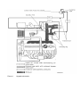
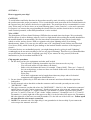
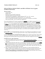
In picture 1 you can find schematic of the Tuoma Perfection upgrade system. The flexible hoses H1
and H2 from engine department to cockpit must go through firewall. Most of the persons are using
original through hole´s already existing like the Motronic ECU unit wiring harness through hole. Make
sure that those holes are sealed afterwards by using silicone or compatible material. It is also possible to
make a new through hole beside the Motronic ECU wiring harness. Special equipment needed is sold in
any well equipped car accessory shop, also rubber covers for this new hole should be available in the
same shop.
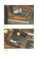
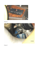
In the cockpit, it is recommended that the control valve A2 is located near to gear shift lever as seen in
the pictures 2, 3 and 4. It is the most logical place and it is easily available when adjuctment is needed.
It is also VERY important to install the pressure gauge in order to follow up the boost. With too high
boost one can easily blow up the engine. It is also needed when the system is adjusted. The output to
boost gauge can be taken anywhere in the pressurised side of the turbo. Example can be seen in picture 6 .
Installation in the engine department:
1. Connect the original air hose (H3) from turbo to the lower connector of the wastegate.
2. Connect hose H2 from the control valve A2 to the upper connector of the wastegate and secure it with
clamp ring.
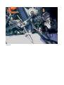
3. Connect hose H1 from the control valve A2 to proximity of the turbo with a spindle as seen in picture
5. Do not drill the hole too close to the turbo mechanism! Also these valve hoses are secured by
using clamp rings. Basicly it can be connected to any place where intake air is pressurised after turbo.
But the nearer it is to turbo charger, the less delay there is in the control. That is the only reason why
it should be as near the turbo charger as possible.
4. Make sure that all pressurised hoses, tubes and connections are in good condition without any
leakages. With low-boost standard set-up you may have not noticed weak spots, but the new set-up
will not forgive anything! Pay special attention to the hose from intake manifold to fuel pressure
regulator! If that is leaking you will immediately run into problems with lean mixture and you can not
make proper first time set-up as described in the User Manual.
Picture 1
Upgrade schematic
Picture 2
Picture 3
Picture 4
Picture 5
Picture 6
APPENDIX 1
How to upgrade your chip?
CAUTION!
To avoid failures and faulty functions in the product caused by static electricity everybody who handles
the product must take proper precautions. To be certain that the used protection devices indeed function in
the expected way, they must be checked on a regular basis. The protection device recommended is a wrist
wrap. Wrist wrap is a device where are at least following parts; a wrist "bracelet", a wire and a connector.
It´s purpose is to connect the person handling the electrical devices and the electrical device itself in the
same electrical potential, so that ESD phenomena´s can be avoided.
What is ESD?
The phenomena of Electro Static Discharge (ESD) has been around since time began. We occasionally
feel the effects of such a discharge when we receive a slight shock after touching the metallic doorknob or
the metallic handle of an automobile. We first learn about electrostatics in basic physics back in high
school or earlier, and we observe ESD on a gigantic scale when lightning strikes occur during
thunderstorms. About 5-10 years ago, the major cause of IC (integrated circuit) failures was Electrical
Over Stress (EOS), which results in gross damage to the internal metallic structure of the integrated
circuit´s.
If electrical devices are not handled properly, you might damage them by giving it small "lightning"
eventhough you do not notice anything or can see any physical damage. Therefore it is recommended that
use professional person in order to upgrade your chip. If you want to do it by yourself, follow the
instructions so you do not them harm the PCB.
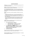
Chip upgrade procedure:
1. Be sure that you have the equipments and other stuff needed.
- You will need a soldering iron and the tip of the iron can not be very big.
- You will need solder wire (the thinner, the better)
- Solder wick, the thinner the better, for example 1.5mm (0.060"). There are 1.5 meter (5
feet) in each package, at least two-three are needed. Solder wick is used for unsoldering
the integrated circuit.
- Wrist wrap.
- All of these equipments can be bought from almost any shops who sell electrical
components and equipments (Radio Shack etc.)
2. Be sure that the ignition key is OFF and remove the motronic unit located behind the right front
loadspeaker.
3. Put the motronic unit to the table so that the connector end is towards you and you can see the
"MOTRONIC" –label.
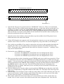
4. The upper connector (on that side where the "MOTRONIC" –label is) is the "transmission connector"
and the lower one is the "engine connector". Put the wrist wrap on your wrist and connect the other
end to the lower connector´s ("engine connector") pin number 19 (which is ground, other ground
pin´s are 5, 6 and 23). There are 35 pin´s in the "engine connector". Ground pin´s are 5, 6, 19 and 23.
Pin number 1 is on the right side of the upper row and 18 is the left side of the upper row. Pin number
19 is the right side of the lower row and pin number 35 is the left one of the lower row. Follow up all
the time that the wrist wrap is connected.
5. NOTE! The motronic unit case (light alloy) is not grounded so it does not help if you connect the
wrist wrap to the motronic unit case.
"Transmission connector"
18
1
35
19
"Engine connector"
Pin number 19
6. Open the lid. The one to be opened is the one "MOTRONIC" label on it. There are 9 small metal
clamps on the lid. Three of them on the connector side, two on each aside and two on the back. Use
screwdriver in order to remove the lid. Do NOT bend the clamps, just put screwdriver under the
right clamp and lift it a bit. There should now be a small opening between the lid and the motronic
unit case. Put the screw driver in the middle, lift a bit and then to left and lift it then carefully on the
both aside and then the lid can be taken away.
7. Open the screws (four of them), remove the rubber cap in the middle of the PCB (printed circuit
board) and remove the white teflon shield.
8. Lift the PCB from the non-connector end a bit and push the connector so you can open the motronic
unit like a book. Those two PCB´s are connected together by using a flat cable, do not damage it.
9. Now you have a possibility (if you want) to connect the wrist wrap to other ground point inside the
motronic unit. There are few cylinder shape electrolytical capasitors in horizontal position in the
PCB´s. The ground can be found from the other end of the capasitor´s (opposite + -marking). Wrist
wrap can be connected there.
10. Find out the correct EPROM to be changed.
- If you have four EPROM in your PCB, the one to be changed is the "S723".
- If you have two EPROM in your PCB, the one to be changed id the "S722".
- If you have one EPROM in your PCB, the one to be changed id the "S720".
11. When you sure that you have located the correct EPROM, make a note which way around it is. There
is a small dent on the other side of the EPROM in the middle and that shows on which end is the pin
number 1. You can also notice a silkscreen printed on the PCB, the thick white line under the EPROM
tells the polarization of the EPROM. When installing a new chip, the thick silkscreen and the dent in
the EPROM must be on the same side. Turn the PCB and find out the pin´s belonging to the
EEPROM you have to change. And when you are sure that you have located the correct pins, the
unsoldering can be started.
12. Take the soldering iron, clean the solder tip and resolder the EPROM pins (on that side of the PCB
where is no components) by using little amount of thin solder wire. This helps when removing of the
solder starts.
13. Take the solder wick and start to remove solder by using solder wick. If the solder does not come out
easily in the first time, resolder it and try again. Remove the solder as well as you can. If the solder
has been removed properly, you should see through the hole.
14. When all the solder have been removed from via´s, turn the PCB (open it like a book) other way
around. Now it is time to remove the solder from the other side (component side). One does not
always manage to remove all the solder from the bottom, so rest of the solder must be removed from
the component side. Take the solder wick and remove the solder. Be carefull and do not harm those
plastic capasitors standing in vertical position.
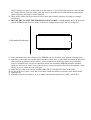
15. When all the solder have been removed, move those pins carefully sideways by using for example
screwdriver.
16. DO NOT TRY TO LIFT THE EPROM BY USING FORCE, it might damage the PCB. Push and
pull the EEPROM sideways two times, it cause less damage than trying to lift it by using force.
Push and pull sideways
17. If the instructions have been followed, the EPROM can now be taken away without using any force.
18. Install the socket right way around (there should be a dent, hole or other kind of marking in the socket
which tells the polarization of the socket). It does not make any difference which way around the
socket is soldered but it is easier to remember which way around the EPROM should be installed.
Solder the socket. It is easier if you solder first one corner pin and then the pin on the opposite corner.
Then it is easy to solder the rest of the pins.
19. Install the new chip to the socket. MAKE SURE THAT IT IS RIGHT WAY AROUND.
20. Put the PCB on it´s place, screw the screws back, install the rubber cap and the white teflon shield.
21. Install the lid.
22. Install the motronic unit back to your car (make sure that the ignition key is OFF) and ENJOY.