1
3.1.1 Fully Three-Dimensional Surface Modeling
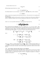
In the fully three-dimensional approach we developed as part of this effort, Surfacer was used to “fit” a
NURBS representation to the actual point cloud data. The main advantage of this approach is that the
three-dimensional nature of the ice accretion can be retained. The primary disadvantages are the difficulties
associated with filtering three-dimensional point cloud data and the surface fitting itself. This technique uses
Surfacer to fit a NURBS surface to the iced wing data in conjunction with the following strategy:
1. Extract trailing edge and leading edge curves.
2. Segment the ice wing data into two parts - wing top and wing bottom.
3. Extract side boundary curves of wing top and wing bottom.
4. Fit NURBS surfaces to the wing top and bottom points using the boundary curves and point cloud
data.
This approach is described in detail in the Appendix. We note that obtaining the boundary curves was time
consuming because of the manual interaction needed to clean up the two-dimensional sections. Further, the
three-dimensional point cloud needs to be manually filtered.
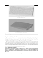
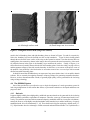
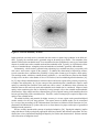
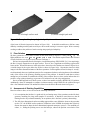
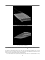
A filtered three-dimensional point cloud and the surface generated using this approach are shown in
Figure 2. There are significant oscillations in the generated surface near the boundary curves. Defining
curves that pass near the tips of the horns and split the upper and lower surfaces into two surfaces each can
reduce these oscillations and reduce the maximum position error by more than 50%. However, this approach
introduces visible slope discontinuities at the surface intersections. These artificial slope discontinuities
occur at critical regions and could pose potentially serious problems for the flow solver as far as accuracy of
the solution.
3.1.2 Pseudo Three-Dimensional Surface Modeling
Choo [9] suggested an alternative approach that is based on lofting two-dimensional chordwise slices of the
data. The primary advantage of this approach is that the needed two-dimensional slices can easily be filtered
to eliminate noisy data points. The disadvantage is that the spanwise resolution is limited by the number of
manually generated chordwise slices. Once the slices are generated and filtered, Surfacer is used to loft a
surface between the chordwise slices using the procedure outline below:
1. Select several spanwise positions
2. Generate chordwise slices of the point cloud at each spanwise station
3. Manually “clean” (filter) the slices to eliminate obviously bad data points
4. Generate a lofted surface between the slices using the two-dimensional sections
5. Generate a NURBS description using Surfacer
We note that to model a three-dimensional surface with significant spanwise variation, it will be necessary
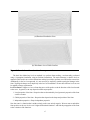
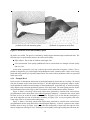
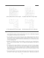
to employ numerous stations across the span. Figure 3(a) shows the manually denoised chordwise profiles
at different spanwise stations and Figure 3(b) shows a wire-frame view of the lofted surface.
4