1
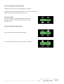
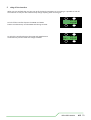
User Manual BB3 BB7 BB3 contents contents INTRO,RIGGING, RIGGING,SET SETUP UP&&MODES MODES INTRO, SAFETY SAFETY FIRST FIRST THE BB7 BB2x2 BB3 RIGGING RIGGING SET UP UP SET MODES MODES MODES A GRAPHICAL OVERVIEW MODES A GRAPHICAL OVERVIEW page page 3 3 page page 5 page 6 6 page page 7 7 page page 8 page 8 page 15 page 12 OPERATINGINSTRUCTIONS INSTRUCTIONS OPERATING STAND FUNCTIONS STAND ALONE ALONE FUNCTIONS STORING DMXINPUT INPUTAS ASAAMEMORY MEMORY STORING AA DMX CREATING AA MEMORY CREATING MEMORY RECALLING AA MEMORY RECALLING MEMORY CREATING AA CHASE CREATING CHASE page page 13 16 page page 13 16 page 14 17 page page 19 page 17 page 21 page 18 THETECHNICAL TECHNICALSTUFF STUFF THE CELL ORIENTATION TECHNICAL SPECIFICATIONS CELL ORIENTATION TROUBLE TECHNICALSHOOTING SPECIFICATIONS QUICK RESET UNIT DIMENSIONS DRAWING TROUBLE SHOOTING QUICK RESET APPENDICES APPENDIX 1 APPENDICES APPENDIX 2 APPENDIX 1 APPENDIX 2 ROHS COMPLIANCE AND WEEE DIRECTIVE INSTRUCTIONS SERVICE CONTACT DETAILS ROHS COMPLIANCE AND WEE DIRECTIVE INSTRUCTIONS SERVICE CONTACT DETAILS page 24 page page 20 22 23 page page 23 23 26 page page 25 24 28 page 25 page 27 page 26 29 page 27 30 page 28 page 29 BB7 USERS MANUAL - PAGE 2 BB3 SAFETY FIRST WARNING! Read the safety precautions in this section before installing, powering, operating or servicing the BB4 3 The following symbols are used to identify important safety information in this manual: Warning! Safety hazard. Risk of severe injury or death Warning! LED light emission. Risk of eye injury Warning! Hazardous voltage. Risk of lethal or severe electric shock Warning! Fire hazard ! Read this manual before installing, powering or servicing the fixture, follow the safety precautions listed below and observe all warnings in this manual. If you have questions about how to operate the fixture safely, please contact I-Pix. Warning! Class 2M LED product. Do not look into the beam from a distance of less than 40 cm (16 inches). Do not stare into the beam for extended periods at a short distance. Do not view the beam directly with optical instruments. This product is for professional use only. It is not for household use. This product presents risks of severe injury or death due to fire hazards, electric shock and falls. BB4 USERSMANUAL MANUAL - PAGE 3 BB3 USERS PROTECTION FROM ELECTRIC SHOCK Shut down power to the entire installation at the building’s main power distribution board and lock out power (by removing the fuse for example) before carrying out any installation or maintenance work. Disconnect the fixture from AC power before removing or installing any cover or part and when not in use. Disconnect the fixture from AC power before removing or changing the fuse. Always ground (earth) the fixture electrically. Use only a source of AC power that complies with local building and electrical codes and has both overload and ground-fault (earth-fault) protection. Connect this fixture to AC power either using the supplied power cable or via 3- conductor cable that is rated minimum 20 amp, hard usage. Suitable cable types include ST, SJT, STW, SEO, SEOW and STO. The voltage and frequency at the power outlet are the same as the voltage and frequency applied to the power inlet. Only connect devices to the power outlet that accept this voltage & frequency. Before using the fixture, check that all power distribution equipment and cables are in perfect condition and rated for the current requirements of all connected devices. Do not use the fixture if the power cable or power plug are in any way damaged, defective or wet, or if they show signs of overheating. PROTECTION FROM FIRE Do not attempt to bypass thermostatic switches or fuses. Replace defective fuses with ones of the specified type and rating only. Provide a minimum clearance of 0.1 m (4 in.) around fans and air vents. Do not modify the fixture Apart from I-PIX accessories do not stick filters, masks or other materials directly onto the light. PROTECTION FROM INJURY when Do not hang fixtures from each other. Use two OMEGA clamps per fixture or I-PIXrigging SINGLE or DOUBLE YOLKS when suspending. horizontally. When suspending the fixture, ensure that the structure and all hardware used can hold at least 10 times the weight of all devices suspended from them. Use two secondary attachments (such as a safety cable) to secure each fixture. Secondary attachments must be able to hold at least 10 times the weight of all devices suspended from them and must be installed as described in this manual. Check that all external covers and rigging hardware are securely fastened. Block access below the work area and work from a stable platform whenever installing, servicing or moving the fixture. The LED emission presents a hazard to eyesight at a distance of 4 - 40 cm (1.6 -16 inches) when the eye is exposed to the beam for longer than 0.25 seconds. Do not look at LEDs from a distance of less than 40 cm (1 ft. 4 in.) without suitable protective eye wear. Do not look at LEDs with magnifiers or similar optical instruments that may concentrate the light output. BB4 USERSMANUAL MANUAL - PAGE 4 BB3 USERS BB4 washlight i-PIX BB 34 Washlight The BB 34 washlight provides the user with an energy saving high power light. Three Four powerful light sources gives the feel and look of a modern light fixture. LED in origin, the appearance from the three four blended sources shows no visible appearance of existing led technology yet has the performance we have all come to understand from this novel form of light. The BB 234 washlight washlight,isisequipped equipped with four custom Light Engines It's one of the highest powerled point twocustom The BB with three light engines. Its from one ofLamina. the highest power point light source source led light available. It is the homogenized source of the three saturate colours that makes our colour light available. It is the homogenized source of the three saturate colours that make our colour mixing so good. mixing so good. The performance of these light engines to i-pix's exacting colour specifications gives a tighter tolerance and improved colour performance, which makes tungsten lighting performance from the BB 34 possible. Daylight temperatures can also be found with ease and finally a fixture that does not need a nudge from amber to compensate. The whites are believable and full of low power energy, which makes one wonder if the source is really an led engine. The BB 34 has a super smooth control with 16 bit resolution, enhancing the feel of the fixture when wishing to emulate the tungsten performance you would expect from pre existing fixtures. Different operating modes ensure ease of use. With consumption of 120 90 watts, the fixture draws half and amp on full @ 240 volts. BB3 USERS BB4 USERSMANUAL MANUAL - PAGE 5 Rigging a BB43 horizontally To rig a BB43 horizontally use the OMEGA brackets supplied with the lamp. These would have your clamp of choice bolted on to them. TheOMEGA obrackets each o each oend oeach end each &ets obe the end &each end the aets middle &be & middle the end the middle obe & of each the of the the middle end lamp of of lamp the each & the using the lamp ofeach using end lamp the middle &the using & the lamp the using the camlocs. middle cof the middle using the the ctmiddle cend of lamp ofthe c& the using lamp lamp the using using ccamlocs. the the c cthe The can be attached to each end &end the middle of the lamp using the OMEGAbrackets can ets can can attached be can attached attached tmiddle attached to toeach ets ets to can can tached be be end attached attached to & each the tthe the of the middle lamp of using the lampc using the c First place the pins in the receptacles with the levers facing out place thecamloc camloc amloc amloc pins pins amloc in in in recept pins the recept amloc inturn recept the receptacles amloc pins amloc in pins the pins receptacles in with in the the the recept recept with the levers facing out First acles with acles the acles with the with the rthe levers levers fthe acles flevers acles acles facing the with with levers out the the facing levers levers flev out fwise. s awith quarter alevers quarter turn clock turn swise. afwith quarter clock swise. aer quarter turn wise. turn clock clock turn wise. clock wise. then to secure the s aacles brackets quarter sspins turn athe giv quarter clock clock wise. then to secure the brackets give the levers a quarter turn clock wise. L A ht lig e Make absolutely sure all four attachment points are secure BEFORE t shrigging the lightthALWAYS secure the lamp to wn the truss, pipe e.t.c. with two safety bonds. One attached to the lampothrough ing safety point hr shown in fig 1 t in figgthe L ached toother the yolk through point shown in figpoint 2 NEVER thrin fig 2 NEVERr through g 2 thtr A othe the attached to the safety yolk through the safety shown orRtoyoke. the brackets. h E VuEgh N E g i OR tahme pl 2 NVEER th the saf r ineg l g ir ggth n fi thr oug E i R ho OR o n EVE w2 N rt o hig f s n n ti fig 2 fig 2 w ho ts fig fig 2 2 fig 2 t shown in fig 2 NEVER through torshown to theinbrackets. fig 2 NEVER thr fig 1 BB4 USERSMANUAL MANUAL - PAGE 6 BB3 USERS 2 vertically Rigging a BB4 To rig a BB4 vertically use the SINGLE or DOUBLE YOLK hanging brackets. The brackets can be supplied as accessories for the lamp. You would obviously have your clamp of choice bolted on to them. The YOLK brackets can be attached to the top, middle or the lamp using the camlocs. To rig a BB 3 horizontally use one of the OMEGA brackets supplied with the lamp. These would have your clamp of choice bolted on to them. First place the camloc pins Lin the receptacles with the The OMEGA bracket can be attached to the side of the lamp using the camlocs. tA levers facing out the correct gh way. i l Then to secure the ebrackets turn the levers a quarter h tturn t sh sho clock wise.g t o tA h lig L e th g wnthe camloc wn as shown. First place pins in the in hr receptacles with the levers facing hr ginbrackets g t t in figthe i n g Then to secure give the levers a quarter turn clockwise. f i g 2 hr ouER shown in fig 2 NEVERr through g r oorRto the brackets. t shown in fig 2 NEVER tNE V or ghto the brackets. E p2 tNhEVEVuEgh th E r pthrough R R E V E E e O am 2 N R th saf O am 2 N R th the saf l l r r he n fig he n fig t t o ni o ni w w ho ho s s t t fig 2 fig 2 amlocs. fig 2 fig fi 2 fig 2 2 g fig 2 fig fig 2 2 WRONG fig 2 t shown in fig 2 NEVER through torshown to theinbrackets. fig 2 NEVER t shown thr in fig 2 NEVER through torshown to theinbrackets. fig 2 NEVER thr Make absolutely sure both attachment points are secure BEFORE rigging the light. ALWAYS secure the lamp to the truss pipe e.t.c. with two safety bonds as shown on the previous page. BB4 MANUAL - PAGE 7 BB3 USERS USERS MANUAL SET UP 1. Select appropriate dimmer curve The BB43 offers a choice of two dimmer curves. 1 LINEAR - the output increases directly with dmx input. 2 ENHANCED - the first 10% of the output is controlled over the first 50% of the DMX input. First press the button under the MORE legend. 4INVRT1 ADDR 001 MODE 3 5CH MORE PRESS PRESS Then press the PROFILE button. Then select the appropriate dimmer curve. linear LIN. PROFILE MAN CHASE STORE PRESS CURV-LIN BACK ON PRESS Or enhanced ENH. 2 Disable or enable user interface backlight Whilst in PROFILE you may choose to switch off the user interface backlight. When you press the button above BACK ON the legend will change to BACK OF and the backlight will go out 5 seconds after the interface is last used, though the backlight will come back on whenever any button is pressed. When you press the button above BACK OF the legend will change to BACK ON and the backlight will remain lit constantly. CURV-ENH BACK ON BACK ON shows the current status of the backlight PRESS CURV-LIN BACK ON PRESS CURV-LIN BACK OF BB3 MANUAL BB4USERS USERS MANUAL - PAGE 9 8 3 Select appropriate operating mode The a choice ten operating modes. These modesThese modes 3gives TheBB3 BB4 will you gives you aof choice of ten operating modes. will enable you to set up the lamp in the most appropriate way for the many different jobs the lamp will be used for. The nuts and bolts of the modes are described in detail in pages 12 to 15. To select a mode Keep the button below the MODE legend depressed go through the modes, just before the one you desire stop, then press once. 4INVRT1 ADDR 001 MODE 1 3CH MORE PRESS 4 Select appropriate DMX address PRESS First press the button above the ADDR legend. Then change the address using the 100s,10s & 1s buttons. 4INVRT1 ADDR 111 MODE 1 3CH MORE PRESS 100s 10s ADDR 011 1s BB4 9 BB3USERS USERS MANUAL MANUAL - PAGE 10 press the button above 4INVRT1. Keep the button below the MODE legend depressed go 2 the The BB4 will modes, gives you a choice operating modes. through just before of theten one you desire stop, These modes will enable you to set up the lamp in the most appropriate way for the then press once. many different jobs the lamp will be used for. The nuts and bolts of the 56 locking off the interface modes described in detail in pages 12 to 15. 5 inverting the cells 5 inverting theare cells 4INVRT1 ADDR 001 MODE 1 3CH MORE PRESS When you are satisfied that you have set up all the lamp’s parameters to your liking it is possible to lock off 4 Select appropriate DMX the that you the dont inadvertently anything when focusing etc. Should you wishinterface to change running order ofaddress the cells so instead running. Should you wishsotothe change running order ofchange thethat cells so thatof instead of running. To select a mode Keep the button below the MODE legend depressed go through the modes, just before the one you desire stop, then press the once. First press button above the ADDR legend. To lock off the interface depress the MORE and ADDR buttons simultaneously and the MORE will change to LOCK. they run they run 4INVRT1 ADDRPRESS 001 MODE 1 3CH MORE 1234 1234 4 Select appropriate DMX address 4321 4321 Then change the address using the 100s,10s & 1s buttons. To unlock the interface depress thethe LOCK andlegend. ADDR buttons First press the button above ADDR Press the button above 1NORM4 Press the button above 1NORM4 simultaneously and the LOCK will change to MORE. 1NORM4 002 4INVRT1 ADDR 111 PRESS 9 20CH MODE 1 3CH MORE 1NORM41NORM4 shows the current shows thePRESS current orientation of the cells. orientation of the cells. PRESS PRESS PRESS PRESS 1NORM4 1NORM4 ADDR 002ADDR 002 MODE 9 20CH MORE MODE 9 20CH MORE 100s 1NORM4 ADDR 002 4INVRT1 ADDR011 111 10s 1sMORE 9 20CH LOCK MODE 1 3CH PRESS THIS IS AN EXTREMELY USEFUL FUNCTION IF SOMEONE HASTHE RIGGED THEWAY WRONG WAY ROUND! THIS IS AN EXTREMELY USEFUL FUNCTION IF SOMEONE HAS RIGGED LAMPTHE THELAMP WRONG ROUND! Then change the address using the 100s,10s & 1s buttons. return To returnTo them to them to 1234 1234 PRESS PRESS 100s ADDR 011 - PAGE 11 BB4 USERS MANUAL 10s PRESS 1s 4INVRT1 4INVRT1 ADDR 002ADDR 002 MODE MORE 9 20CH MORE MODE 9 20CH the button above 4INVRT1. press thepress button above 4INVRT1. locking off the interface 6 locking6 off the interface When you are that satisfied that you have all the lamp’s parameters to your it istopossible When you are satisfied you have set up all set theup lamp’s parameters to your liking it is liking possible lock offto lock off the interface so that you dont inadvertently change anything when focusing etc. the interface so that you dont inadvertently change anything when focusing etc. PRESS Tothe lockinterface off the interface depress MORE To lock off depress the MOREthe and ADDRand ADDR buttons simultaneously and the willtochange buttons simultaneously and the MORE willMORE change LOCK. to LOCK. PRESS 1NORM4 1NORM4 ADDR 002ADDR 002 MODE MORE 9 20CH MORE MODE 9 20CH PRESS PRESS BB2 MANUAL BB4USERS USERS MANUAL - PAGE 10 9 PRESS unlock the interface depress ADDR buttons To unlockTothe interface depress the LOCKthe andLOCK ADDRand buttons simultaneously and the LOCK will change to MORE. simultaneously and the LOCK will change to MORE. PRESS 1NORM4 1NORM4 ADDR 002ADDR 002 MODE LOCK 9 20CH LOCK MODE 9 20CH PRESS PRESS BB2 MANUAL BB4USERS USERS MANUAL - PAGE 10 9 BB3USERS USERS MANUAL - PAGE 11 10 BB4 BB4 USERS MANUAL MANUAL - PAGE 11 THE OPERATING MODES The BB43 has 10 different operating modes to suit different uses, programming styles and dmx configurations. MODE 1 - 3 channels 8 bit The most simple, ideal for fast programming or limited dmx line space and as a node on a media server. All 4 cells are treated as 1 with the 3 channels red, green & blue affecting the whole lamp ch1 - red all cells ch2 - green all cells ch3 – blue all cells MODE 2 - 6 channels 16 bit Ideal for fast programming or limited dmx line space and as a node on a media server, with a greater resolution over the colours. All 4 cells are treated as 1 with the 6 channels red, green & blue affecting the whole lamp. ch1 - master intensity high byte all cells ch2 - master intensity low byte all cells ch3 – strobe all cells ch4 – red high byte all cells ch5 - red low byte all cells ch6 – green high byte all cells ch7 - green low byte all cells ch8 – blue high byte all cells ch9 - blue low byte all cells Ideal for use with media servers where dmx line space may be a consideration. Each cell can be individually coloured with its own red green blue channels. (most useful when each cell is patched individually -3ch) MODE 3 - 5 channels 8 bit Ideal for fast programming or limited dmx line space with overall dimming & strobe control. All 4 cells are treated as 1 with the 5 channels dim, strobe, red, green & blue affecting the whole lamp ch1 - master intensity all cells ch2 - strobe all cells ch3 - red all cells ch4 - green all cells ch5 - blue all cells R Mode 1 - 3 ch 8 bit Mode 2 - 6 ch 16 bit rr RR bb Ideal for fast programming or limited dmx line space with overall dimming & strobe control and a greater resolution in control over the dimming and colours. All 4 cells are treated as 1 with the 5 channels dim, strobe, red, green & blue affecting the whole lamp. MODE 5 - 12 9 channel 8 bit ch1 - red high byte all cells ch2 - red low byte all cells ch3 - green high byte all cells ch4 - green low byte all cells ch5 - blue high byte all cells ch6 - blue low byte all cells gg MODE 4 - 9 channels 16 bit GGG BB B rr R RRrr R R gG gg GGg b b B BGG Bb Mode 3 - 5 ch 8 bit b ch1 - red cell 1 ch2 - green cell 1 ch3 - blue cell 1 ch4 - red cell 2 ch5 - green cell 2 ch6 - blue cell 2 ch7 - red cell 3 ch8 - green cell 3 ch9 - blue cell 3 ch10 - red cell 4 ch11 - green cell 4 ch12 - blue cell 4 rr R RR R R R R gGGg G Mode 4 - 9 ch 16 bit B B B BGG bb B R Mode 5 - 12 9 ch 8 bit r g r br ggg r b bg rb r g bg r r bgbg r g bbr b gg r r br g b rbg b G B r g b 12 BB4 USERSMANUAL MANUAL - PAGE 11 BB3 USERS MODE 6 - 18 24 channel 16 bit MODE 8 - 21 27 channel 16 bit Ideal for use with media servers, with a greater resolution over the colours. Each cell can be individually coloured with its own red green blue channel. (most useful when each cell is patched individually -6ch) ch1 - red high byte cell 1 ch2 - red low byte cell 1 ch3 - green high byte cell 1 ch4 - green low byte cell 1 ch5 - blue high byte cell 1 ch6 - blue low byte cell 2 ch7 - red high byte cell 2 ch8 - red low byte cell 2 ch9 - green high byte cell 2 ch10 - green low byte cell 2 ch11 - blue high byte cell 2 ch12 - blue low byte cell 2 ch13 - red high byte cell 3 ch14 - red low byte cell 3 ch15 - green high byte cell 3 ch16 - green low byte cell 3 ch17 - blue high byte cell 3 ch18 - blue low byte cell 3 ch19 - red high byte cell 4 ch20 - red low byte cell 4 ch21 - green high byte cell 4 ch22 - green low byte cell 4 ch23 - blue high byte cell 4 ch24 - blue low byte cell 4 High resolution colour control over each individual cell with a strobe and a high resolution master intensity having overall control over all 4 cells. ch1 - master intensity high byte all cells ch2 - master intensity low byte all cells ch3 - strobe all cells ch4 - red high byte cell 1 ch5 - red low byte cell 1 ch6 - green high byte cell 1 ch7 - green low byte cell 1 ch8 - blue high byte cell 1 ch9 - blue low byte cell 1 ch10 - red high byte cell 2 ch11 - red low byte cell 2 ch12 - green high byte cell 2 ch13 - green low byte cell 2 ch14 - blue high byte cell 2 ch15 - blue low byte cell 2 ch16 - red high byte cell 3 ch17 - red low byte cell 3 ch18 - green high byte cell 3 ch19 - green low byte cell 3 ch20 - blue high byte cell 3 ch21 - blue low byte cell 3 ch22 - red high byte cell 4 ch23 - red low byte cell 4 ch24 - green high byte cell 4 ch25 - green low byte cell 4 ch26 - blue high byte cell 4 ch27 - blue low byte cell 4 MODE 7 - 14 8 channel 8 bit Colour control over each individual cell with a master intensity and strobe having overall control over all 4 cells. ch1- master intensity all cells ch2 - strobe all cells ch3 - red cell 1 ch4 - green cell 1 ch5 - blue cell 1 ch6 - red cell 2 ch7 - green cell 2 ch8 - blue cell 2 ch9 - red cell 3 ch10 - green cell 3 ch11 - blue cell 3 ch12 - red cell 4 ch13 - green cell 4 ch14 - blue cell 4 g gg g g gg g G G G G G G G bB B BBb bBb BB R Mode 6 - 18 24 ch 16 bit R G R BG RB G R G RR B BGG G BB RR GG RR BGG B B R GGG RR B BB B R G RBG B rRr RR gGRGGR g r rR RR gGRGR gG Mode 7 - 14 11 ch 8 bit Mode 8 - 27 21 ch 16 bit r g r bg r bgg r bgg rb rr bbbggg rrbg b b r gg rr bg b rbg b R G R BG RB G R G RB R BG BB RR GG R GG R B BB BGBG bBb r g b BGBG RRR GGG B B B b bB R G RBG B BB2 BB4USERS USERSMANUAL MANUAL - PAGE 13 12 MODE1010- 27 36 channel 16 bit MODE MODE99- 20 MODE 15 channel 8 bit Ideal for control over all aspects of programming where dmx line space may be a consideration. For each cell there is individual control over master intensity, strobe and red green colour mixing. (most useful when each cell is patched individually -5ch). ch1- master intensity all cells 1 ch2 - strobe all cells 1 ch3 - red cell 1 ch4 - green cell 1 ch5 - blue cell 1 ch6- master intensity all cells 2 ch7 - strobe all cells 2 ch8 - red cell 2 ch9 - green cell 2 ch10 - blue cell 2 ch11- master intensity all cells 3 ch12 - strobe all cells 3 ch13 - red cell 3 ch14 - green cell 3 ch15 - blue cell 3 ch16- master intensity all cells 4 ch17 - strobe all cells 4 ch18 - red cell 4 ch19 - green cell 4 ch20 - blue cell 4 R R G R G B G B B rr R RrR r g R rg G rrrbgGR Gg R bg Rr rR BG B Rrrrrbg R G rbgg BG Grg R G b b RR b BG B R g R rgrg G g G rbb G G B rbb BG rB Gg B bb 15 ch 8 bit Mode 9 - 20 g b g bg bg bg b g b g b b Rrr RR R G R BR RGgRrg GrG G Mode 10 - 27 36 ch 16 bit R G B G RRRRR B BGG B BB BG R R G R R g g r R G GrGGGG GRRbRb B B R B B BG B R RGGG RRg G g G G R G B BbBb B R G BG R BB GG BbBb Ideal for control over all aspects of programming with high resolution master intensity, high resolution colour control and a strobe control over each individual cell. (most useful when each cell is patched individually - 9ch). ch1 - master intensity high byte cell 1 ch2 – strobe cell 1 low byte cell 1 ch2 – strobe cell 1 ch4 - red high byte cell 1 ch5 - red low byte cell 1 ch6 - green high byte cell 1 ch7 - green low byte cell 1 ch8 - blue high byte cell 1 ch9 - blue low byte cell 1 ch10 - master intensity high byte cell 2 ch11 - master intensity low byte cell 2 ch12 – strobe cell 2 ch13 - red high byte cell 2 ch14 - red low byte cell 2 ch15 - green high byte cell 2 ch16 - green low byte cell 2 ch17 - blue high byte cell 2 ch18 - blue low byte cell 2 ch19 - master intensity high byte cell 3 ch20 - master intensity low byte cell 3 ch21 – strobe cell 3 cell ch22 - red high byte cell 3 ch23 - red low byte cell 3 ch24 - green high byte cell 3 ch25 - green low byte cell 3 ch26 - blue high byte cell 3 ch27 - blue low byte cell 3 ch28 - master intensity high byte cell 4 ch29 - master intensity low byte cell 4 ch30 – strobe cell 4 ch31 - red high byte cell 4 ch32 - red low byte cell 4 ch33 - green high byte cell 4 ch34 - green low byte cell 4 ch35 - blue high byte cell 4 ch36 - blue low byte cell 4 R R G R G B G B B BB3USERS USERS MANUAL BB4 MANUAL - PAGE 14 13 MODES A GRAPHICAL OVERVIEW INTENSITY STROBE CHANNEL Mode 1 Mode 2 Mode 3 Mode 4 Mode 5 3 ch 8 bit 6 ch 16 bit 5 ch 8 bit 9 ch 16 bit 9 ch 8 bit 12 rr R RR g g GG b b B BB G Mode 6 Mode 7 24 ch 16 bit 18 14 11 ch 8 bit R R G BG RR G R BBG R BG B RRR GGG R BBG B G RRR GGG B BB rRr RR gGRGGR g r g rrbggg r b bg rb rrrbbgggg r bbb rrrbggg b rbg rb g BGBG B bBb B bbb bb bbB R G RR BGG BB b Mode 9 6 B g Mode Mode Mode ode 77 6887 G Mode Mode ode 8 MASTER r g bb rRr RRrr g gGRGR g G g r rR R RR R gG gGRGR bB bb bBbB G b B BG G B B BG G Mode 8 27 ch 16 bit 21 15 r rR RRG R gGRGR gBGRG R R G B RR GG RB G B R BG B RRR GGG RB G B B BGBGBG RRR GGG B BB b bBB R G RR BGG BB Mode 9 20 ch 8 bit 15 b r g b R G B Mode 10 rr R RrR RrrrgGR rgg G Gg R r b RrbR BG B Rrrrrrg gg R G r Gg R G G b B Rbbb R BG B R rrrg Rgg G G Gg G B brbb b BG gg rr B G bbb B g b g bg bg bg b g b g b r g r bgg r bg rb r r bbggg r bb rr bgg rbg b R G B 36 ch 16 bit 27 Rrr RR rGG gRrgGR RRGR G R G B G RRRBR B BG B B B R R G G R G R R g g r RGbRBb GrGGG G B R BR B B B R GGG R RG RRg G g G G G b B B BBb G BGbb GG RB R BB BB R G BB3 BB4USERS USERSMANUAL MANUAL - PAGE 14 14 Stand alone functions The BB43 is able to run in a stand alone mode without any need of data from a lighting desk. The light is capable of outputting up to 20 programmable memories and 1 chase that steps through these memories. “The light must be in MODE 3 (5ch) for all the stand alone functions to work.” Storing a DMX Input as a Memory However if you have access to a lighting desk a quick and easy way to create multiple or complex memories is to give the light the desired colour information using a lighting desk or similar DMX generating device and use the STORE function. 1 Connect the light to the desk in the usual way making sure the address is correct and the lamp is in MODE 3. 2 Create the desired colour on the lighting desk. 3 Press the button underneath the MORE legend once. 4INURT1 ADDR 001 MODE 3 5CH MORE PRESS 4 Press the button underneath the STORE legend once. PROFILE MAN CHASE STORE PRESS PRESS 5 You should then assign this memory a number using the UP, DOWN buttons. 6 When you are happy this memory has been numbered correctly press the STORE button wait 3 seconds and the display will return to the main menu. UP DOWN MEN 04 STORE UP DOWN MEN 04 STORE PRESS BB4 15 BB3USERS USERS MANUAL MANUAL - PAGE 16 Creating a memory 1 press the button underneath the MORE legend once. 4INURT1 ADDR 001 MODE 3 5CH MORE PRESS 2 press the button underneath the MAN (manual) legend once. PROFILE MAN CHASE STORE PRESS 3 press the button underneath the PROG MEM (program memory) legend once. USE MEM PROG MEM PRESS You are now presented with the first variable of your memory which is the Master Intensity (MINT). The default value for the MINT is 100% - intensity full. If you wish to alter this value use the buttons above and below the UP & DOWN legends until you have the desired % value. UP MINT 100% DOWN UP MINT 080% DOWN PRESS PRESS 4 When happy with the MINT value press the button above MINT once. UP MINT 080% DOWN Next you are presented with STRB (strobe) the second variable of your memory which has a default value of 0% - no strobe. UP DOWN STRB 080% In the same way if you wish to alter this value use the UP & DOWN buttons to give you the desired % value. BB4 16 BB3USERS USERS MANUAL MANUAL - PAGE 17 PRESS 5 When happy with the STRB value press the button above STRB once. UP DOWN STRB Now you are presented with the first colour RED (default 0%). UP DOWN RED 000% In the same way if you wish to alter this value use the UP, DOWN buttons to give you the desired %. If you require 100% press the DOWN button. UP DOWN RED 100% 000% PRESS PRESS 6 When happy with the RED value press the button above RED once. UP DOWN RED 100% Next you are presented with the second colour GREEN (default 0%) In the same way if you wish to alter this value use the UP, DOWN buttons to give you the desired % If you require 100% press the DOWN button. PRESS 7 When happy with the GREEN value press the button above GREEN once. UP DOWN GREEN000% Finally you are presented with the third colour BLUE (default 0%). In the same way if you wish to alter this value use the UP, DOWN buttons to give you the desired %. If you require 100% press the DOWN button. PRESS 8 When happy with the BLUE value press the button above BLUE once. UP DOWN BLUE 000% BB4 17 BB3USERS USERS MANUAL MANUAL - PAGE 18 Now you are given the opportunity to store your memory If you are satisfied with all the values you have inputted. If however you think you may have made a mistake or you have just changed your mind then you can return to the start of the memory by pressing MEM button and repeating the above process. If you are happy with you memory you should then assign it a number using the UP, DOWN buttons. 9 When happy with your memory number press STORE. UP DOWN MEM 01 STORE PRESS UP DOWN MEM 01 STORE PRESS UP DOWN MEM 04 STORE UP DOWN MEM 04 STORE PRESS BB3USERS USERS MANUAL MANUAL - PAGE 19 BB4 18 To Recall A Memory 1 Press the button underneath the MORE legend once then. 4INURT1 ADDR 001 MODE 3 5CH MORE PRESS 2 Press the button underneath the MAN (manual) legend once then. PROFILE MAN CHASE STORE PRESS 3 Press the button underneath the USE MEM (use memory) legend. USE MEM PROG MEM PRESS Now you will be offered the first memory MEM 01. This will come on automatically. UP DOWN MEM 01 STORE PRESS 4 To select any other memory simply use the UP, DOWN buttons until you find the memory you want. UP MEM 01 DOWN DMX MODE The memories will come on as you select them. “ IF YOU WISH YOUR MEMORY TO COME ON AS SOON AS YOU GIVE THE LAMP POWER YOU WILL NEED TO PROGRAMME IT AS A TWO STEP CHASE WITH BOTH MEMORIES HAVING THE SAME VALUE” To return to the main menu press the DMX MODE button UP MEM 02 DOWN DMX MODE PRESS BB4 BB3USERS USERS MANUAL MANUAL - PAGE 20 19 Programming a Chase 1 Ensure you have programmed all the memories that will go to make up the steps of your chase. 2 Press the button underneath the MORE legend once.. 4INURT1 ADDR 001 MODE 3 5CH MORE PRESS PRESS 3 Press the button above the CHASE legend once. Now the WAIT TIME will appear this is the first variable of the chase to be set. The WAIT TIME is the time period between cross fades that the colour is held constant for. PROFILE MAN CHASE STORE UP WAIT TIME DOWN 001s PRESS Select the appropriate time (in seconds) using the UP, DOWN buttons. UP WAIT TIME DOWN 002s PRESS 4 When you are happy with the WAIT TIME press the button above WAIT TIME once. Now the XFADE TIME (cross fade time) will appear this is the second variable of the chase to be set. The XFADE TIME is the length of time the light takes to change from one colour to another. UP WAIT TIME DOWN 002s UP XFADE TIME DOWN 002s PRESS Select the appropriate time (in seconds) using the UP, DOWN buttons. UP XFADE TIME DOWN 003s PRESS 5 Once you are happy with the XFADE TIME press the button above XFADE TIME once. UP XFADE TIME DOWN 003s BB3USERS USERS MANUAL 20 BB4 MANUAL - PAGE 21 Now CHASE STRT (chase start) will appear along with the option MEM 1. This will be the first step of your chase. Choose which memory you would like to be the first step of your chase using the UP, DOWN buttons. 6 Once you are happy with the memory that will be your first step press the button above CHASE STRT. Now CHASE END will appear along with the option MEM 1. This will be the last step of your chase. The chase will run through all the memories numbered between the first and last step. PRESS UP CHASE STRT DOWN MEM 01 UP CHASE END DOWN MEM 01 PRESS Choose which memory you would like to be the last step of your chase using the UP, DOWN buttons. UP CHASE END DOWN MEM 02 PRESS 7 Once you are happy with the memory that will be your last step press the button above CHASE END once. Now you will be offered the option USE CHASE, if you wish to simply press yes. The Interface will now say CHASE RUNNING. When you wish to end or change the chase press MENU. UP CHASE END DOWN MEM 03 USE CHASE YES NO PRESS CHASE RUNNING MENU PRESS If you leave a chase running when the light is powered down the chase will resume as soon as the light is powered back up again. ! If the chase does not run try rerecording the first step again BB4 21 BB3USERS USERS MANUAL MANUAL - PAGE 22 Stand alone functions BB3 cell orientation The BB7 is able to run in a stand alone mode without any need of data from a lighting desk. The light is capable of outputting up to 20 programmable memories and 1 chase that steps through these memories. “The light must be in MODE 3 (5ch) for all the stand alone functions to work.” Storing a DMX Input as a Memory However if you have access to a lighting desk a quick and easy way to create multiple or complex memories is to give the light the desired colour information using a lighting desk or similar DMX generating device and use the STORE function. 1 Connect the light to the desk in the usual way making sure the address is correct and the lamp is in MODE 3. 2 Create the desired colour on the lighting desk. 3 Press the button underneath the MORE legend once. 1 MODE 3 2 4 Press the button underneath the STORE legend once. 3 UP DOWN ADDR 001 5CH MORE PRESS MEN 01 STORE PRESS PRESS 5 You should then assign this memory a number using the UP, DOWN buttons. 6 When you are happy this memory has been numbered correctly press the STORE button wait 3 seconds and the display will return to the main menu. UP DOWN MEN 04 STORE UP DOWN MEN 04 STORE PRESS 13 BB3BB7 USERS MANUAL - PAGE 22 BB3 Technical Specifications Dimensions: • Length • Height • Width • Weight 533 mm 291 mm 178 mm 11.4Kg Mechanical design & materials: • Batten • Yoke • Finish aluminium shrouded finned diagonal heatsink folded and welded steel Electro static powder coated black satin Rigging: • Style • Number of positions • Accessory holder • Conventional mounts 12 ¼ turn camloc fasteners 9 rigging locations on yoke fitted with sprung retention flap 2 of 12mm bolt holes fitted at each yoke end Note: unit comes with two Omega rigging brackets to accept 12mm bolts, Electrical: • Input • Current • Power • Fuse • Input • Output 90- 265 Volt 50/60 Hz 0.5 amps @ 240 volts 90 watts total power on full @ 240 volts 20mm x 5mm slow blow 2 amp trailing male IP67 6 pin ( Combined power and data connection ) chassis mounted female IP67 6 pin ( Combined power and data connection ) Note; units comes complete with 16 amp plug and 5 pin male. Control: • DMX channels • User interface • Data type RGB additive colour mixing 3 channels minimum 18 channels maximum weatherproof backlit lcd display with four membrane switches USITT DMX512-A Output: • Source • Optics customised RGB LED light engine 3 x 20° optics with 10°,35° & 45° also available Thermal characteristics: • Operating temperature force air cooled via low airflow/ low noise fans Minimum: -20 degrees C, Maximum:+ 46 degrees C Weather protection: Rated to IP65 20% ~ 90% RH non-condensing Approvals & Compliance: BS EN 55103-1 Harmonics BS EN 55103-2 Immunity BS EN 61000-3-2 Emissions • Humidity max USA / Canada ETL pending BB3 USERS MANUAL - Page 23 18 178mm 80mm 291mm BB3Technical Dimensions Drawing BB1 Specifications 130mm 178mm 533mm 470mm 178mm 291mm 135mm BB3 USERS MANUAL - Page 19 24 TROUBLE SHOOTING DISCLAIMER: Please note that the information contained in this trouble-shooting guide is generalized in nature & cannot account for all possibilities. Any proposed remedies for specific situations should not be considered as absolute or all encompassing. Please seek professional assistance if there is any doubt as to the efficacy of a remedy or of the exact nature of any encountered problem. I-pix provides the information contained herein only as a guide. No response from the light Does the LCD screen light up No Yes Does the unit have a good power supply Yes Is the LCD screen flashing Check the fuse is it blown No Yes Yes There is no signal check DMX input Contact I-Pix for more specific help with your problem, as it could be an internal fault. If you have the technical knowledge & skills you could open up the unit & Yes check for loose connections Replace with the appropriate fuse 4A Mains supply keeps tripping out blowing fuses: Does the mains supply trip before the light/s are given power? Yes No Contact I-Pix for more specific help with your problem, as it could be an internal fault. If you have the technical knowledge & skills you could open up the unit & check for loose connections shorts & faults Does the mains supply trip when the light/s are given power? Yes No Check all external wiring for faults or the supply overloaded. If problem persists contact a competent electrician. Is the mains supply overloaded with the addition of the lamp? Yes Remove some of the load from the supply upgrade the supply rating - split the load across more circuits No When you try the lamp on a different supply does it work Yes Contact a competent electrician to check out the supply that could be faulty BB4 25 BB3USERS USERS MANUAL MANUAL - PAGE 26 25 TROUBLE SHOOTING The fuse on a unit repeatedly blows • • • Are you fitting right rating/type of fuse into unit? Contact I-pix for more specific help with your problem, there may be an internal fault in the unit. If you have the technical knowledge/skills you could look inside the unit and check the internal wiring for a lose connections/shorts and also the power supply is working with a 15v output when there is no load connected to it. Dmx trouble shooting The obvious • It is good practice to connect data line and terminate before switching on device. • Is the dmx line fitted to a buffer and data is being received • Is the dmx data line fitted with a line termination? • Does the unit’s dmx mode set-up match the personality/ profile for the console provided? • Note: the LCD screen flashes intermittently when no data is present BB3 MANUAL 26 BB4USERS USERS MANUAL - PAGE 27 26 QUICK RESET An easy way of returning the light to its default settings. PRESS Before the light is given any power hold down both both buttons on the left hand side of the interface. PRESS Keep the buttons held down as you give the light power. When you see screen with the black boxes let go of the buttons and the next screen will appear. If you do not let go it will stay locked until you let go. PRESS PRESS Then the light will return to MODE 10 ADDR 001 4INVRT1 ADDR 001 MODE10 18 36CH MORE This is a fast way of readdressing a light, that will save you a few button presses BB3USERS USERS MANUAL MANUAL - PAGE 28 27 BB4 27 RoHS AND WARRANTIES I-PIX BB4s 3 COMPLY WITH RoHS RESTRICTIONS I-PIX BB4s 3 are compliant with all of the criteria proposed by the European RoHS directive 2002/95/EC for hazardous material content in electronic and electrical equipment as listed in Annex 1A and 1B of the WEEE Directive. In addition to containing no mercury, the LED light engines have the following environmental advantages over traditional light sources: ! High energy efficiency ! Long lifetime ! Fully dim-able ! Very low IR and UV radiation For attachment of electrical connections I-Pix use lead free solder R C US RoHS 2002/95/EC COMPLIANT WARRANTY STATEMENT 3 produced by I-Pix (seller) extends warranty on all the electronics in the BB4 the Seller for two (2) years from original date of shipment, that the goods sold hereunder are new and free from substantive defects in workmanship and materials. This warranty extends only to the Buyer and not to indirect purchasers or users . Sellers liability under the foregoing warranty is limited to replacement of goods or repair of defects or refund of the purchase price at the Sellers sole option. The above warranty does not apply to defects resulting from the improper or inadequate maintenance, unauthorized modification, improper use or operation outside of Sellers specifications for the product, abuse, neglect, or accident. THE ABOVE WARRANTY IS EXCLUSIVE AND NO OTHER WARRANTY, WHETHER WRITTEN OR ORAL, IS EXPRESSED OR IMPLIED. I-PIX SPECIFICALLY DISCLAIMS THE IMPLIED WARRANTIES OF MERCHANTABILITY AND FITNESS FOR A PARTICULAR PURPOSE - I-PIX Jan 01, 2009 WEEE COMPLIANT WARRANTY STATEMENT 3 produced by the I-Pix (seller) extends warranty on all the L.E.Ds in the BB4 Seller for one (1) year from original date of shipment, that the goods sold hereunder are new and free from substantive defects in workmanship and materials. This warranty extends only to the Buyer and not to indirect purchasers or users. Sellers liability under the foregoing warranty is limited to replacement of goods or repair of defects or refund of the purchase price at the Sellers sole option. The above warranty does not apply to defects resulting from the improper or inadequate maintenance, unauthorized modification, improper use or operation outside of Sellers specifications for the product, abuse, neglect or accident. THE ABOVE WARRANTY IS EXCLUSIVE AND NO OTHER WARRANTY, WHETHER WRITTEN OR ORAL, IS EXPRESSED OR IMPLIED. I-PIX SPECIFICALLY DISCLAIMS THE IMPLIED WARRANTIES OF MERCHANTABILITY AND FITNESS FOR A PARTICULAR PURPOSE - I-PIX Jan 01, 2009 BB4 USERSMANUAL MANUAL - PAGE 29 BB3 USERS 28 SERVICE CONTACT DETAILS Broadstone Mill Broadstone Road Houldsworth Village Cheshire SK5 7DL [Located 4 miles from Manchester airport and the city centre] Tel: 44 (0)161 443 4140 E-mail: [email protected] www.i-pix.com BB4USERS USERSMANUAL MANUAL - PAGE 30 BB3 29 29