1
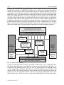
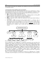
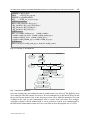
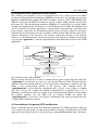
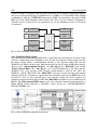
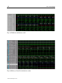
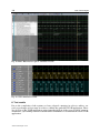
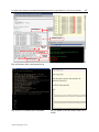
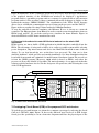
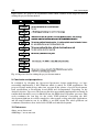
7
An Opencores /Opensource Based Embedded
System-on-Chip Platform for Voice over Internet
Sabrina Titri, Nouma Izeboudjen, Fatiha Louiz, Mohamed Bakiri,
Faroudja Abid, Dalila Lazib and Leila Sahli
Centre de Developpement des Technologies Avancées
Lotissement 20 Aout 1956 Baba Hassen, Algiers
Algeria
1. Introduction
Today, with the explosion of the IP network protocol, communication traffic is mainly
dominated by data traffic, unlike in the past it was dominated by telephony driven voice.
This phenomenon has lead to the emergence of voice over data (VOIP) equipment that can
carry voice, data and also video on a single network. The idea behind VOIP is to use the IP
network for voice services as an alternative to the public switched telecommunication
network (PSTN). The advantages over traditional telephony include: lower costs per call,
especially for long distance calls, and lower infrastructure cost compared to the PSTN. The
market for VOIP equipment has increased dramatically and a lot of solutions are proposed
to the research and industry communities. Each specialised paper that appears shows that
VOIP has an important place in the telephony market, especially in enterprise and public
domain areas. The main challenges in designing a VOIP application are the quality of
service (QoS), the capacity of the gateways and real time computation. Factors affecting the
QoS are line noise, echo cancellation, the voice coder used, the talker overlap and the Jitter
factor. The capacity of the gateway is related to the number of lines that can be supported in
an enterprise environment. An integrated hardware-software development environment is
needed to deal with real time computation. (Dhir, 2001). Most important VOIP solutions
proposed in the market are based on the use of a general purpose processor and a DSP
circuit. In these solutions, parts of the application run on software on the general purpose
processor and the other part of the application runs on the dedicated DSP hardware to meet
some performances requirements. Recently, and with the advance of the microelectronic
technology in one hand, and CAD tools in the other hand, it is possible to integrate a whole
system into a single integrated FPGA chip. Ended, FPGAs have evolved in an evolutionary
and revolutionary way. The evolution process has allowed faster and bigger FPGAs, better
CAD tools and better technical support. The revolution process concerns the introduction of
high performances multipliers, Microprocessors and DSP functions inside the FPGA circuit.
Thus, a new field which integrates VOIP solutions into FPGAs based System on Chip (SoC)
is emerging, particularly the field of embedded VOIP based FPGA platform. Contrarily to
DSP and general purpose processors, FPGAs enable rapid, cost-effective product
development cycles in an environment where target markets are constantly shifting and
standards continuously evolving. Most of these offer processing capabilities, a
www.intechopen.com
146
VoIP Technologies
programmable fabric, memory, peripheral devices, and connectivity to bring data into and
out of the FPGA. Several approaches have emerged from industrial and academic research
to design embedded systems into FPGA, such as the Xilinx approach which uses the
Microblase processor (micro ), the Altera (Altera) approach which is based on the use of the
Nios processor, the IBM approach which uses the Power PC processor and the Opencores
approach which uses the OpenRisc processor (Opencores). Each approach tries to promote
its processor in the market. In this paper, we propose a SoC platform for VoIP application.
This last one is composed of two parts: a software part which is related to configuration of
the VOIP application and which is based on the Opensource Asterisk-PBX platform
(Maeggelen & al.,2007) and a hardware part related to the VOIP Gateway and which is used
to connect the traditional PSTN network to the Internet Network. We concentrate on the
VIRTEX-5 FPGAs family from Xilinx to build the embedded SOC hardware. The final goal is
to implement an embedded VOIP system and where part of Asterisk PBX software is
embedded into FPGA. Due to the complexity of the system, we planed to achieve our
objective in three phases:
•
Phase1: Implementation of a simple VOIP application based on Asterisk and a
commercial Digium TDM card.
•
Phase2: Replace the Digium card and build a new VOIP Gateway based on FPGA and
using the OpenRisc processor;
•
Phase3: Build an embedded Asterisk into the proposed VOIP based FPGA Gateway.
The originality of our approach is the adoption of the OpenCores and Opensource concepts
for the design and implementation of the whole SOC VOIP platform. With analogy to
Opensource-Linux, Opencores is a new design concept which is based on publishing all
necessary information about the hardware. The design specifications, hardware description
language (HDL) at Register Transfer Level (RTL), simulation test benches, interfaces to other
systems are documented. Usually, all this information is not available for free without any
restriction. This new design concept is proposed as a bridge for the technological,
educational and cultural gaps between developing and developed countries. The benefit of
using such methodology is flexibility; reuse, rapid SoC prototyping into FPGA or ASIC and
the entire software and hardware components of the VOIP application are available at free
cost. This can also reduces the whole VOIP cost.
In section 2, general presentation of Voice over IP is given. Section 3 deals with presentation
of the Opencores development platform. In section 4, presentation of the proposed VOIP
Gateway architecture is given. Simulation and synthesis results are given in section 5.
Followed by, presentation of the implementation results. In section 7 the PCB of the
proposed SOC architecture is presented, followed by the presentation of the documentation
phase; and finally, a conclusion.
2. General presentation of voice over IP
Voice over IP had its starts in February 1995 when a manufacturer started marketing software
that enabled a conventional computer equipped with a sound card, microphone and
loudspeaker to phone another PC via the internet. Initially, the voice quality achieved was
unsatisfactory but the principle behind it drew a great attention of public, thus the first area of
application for VoIP: PC-to-PC was established. Subsequent to this introduction a number of
manufacturers concentrated on developing similar software and consequently raised the
question of compatibility among different systems. In 1996, the International
www.intechopen.com
An Opencores /Opensource Based Embedded System-on-Chip Platform for Voice over Internet
147
Telecommunication Union (ITU-T),(ITU, 2007) responded by developing the H.323 standard.
Afterwards, the focus was the possibility of placing long distance calls using voice over IP
known as toll bypass; however this required setting up a connection between the telephone
network (PSTN) and the data network, a task performed by the so called Gateways. The result
has been additional application for VoIP including: PC-to-phone, Phone-to-PC and, when two
gateways are used, Phone- to - phone communication is established. This last option was the
catalyst in the establishment of a new provider group named ITSP (Internet Telephone Service
Provider) that permits telephony over IP within the provider network using prepaid cards. To
date, VoIP refers to the ability to transfer data and voice and also video on the single network.
Figure 1 illustrates the basic operating principle of VoIP.
The human voice initially generates an analog signal. This signal is converted into a bit
stream by an Analog/ Digital (A/ D) converter. And then submitted to a multiple
compression process. The Voice frames are integrated into a voice packet. First RTP (Real
time protocol) packet with a 12 address byte header is created. Then an 8-byte UDP packet
with the source and destination address is added. Finally, a 20 byte IP header containing
source and destination gateway IP address is added.The packet is sent through the internet
where routers ands switches examine the destination address. When the destination receives
the packet, the packet goes through the reverse process for playback. A minimal VoIP
implementation requires two functionalities. First, it should be able to connect to other VoIP
phones and, second, voice data should be carried by the Internet. The first requirement is
fulfilled by using signaling.
The second one is achieved by using speech coding algorithms.
2.1 VOIP signaling
Signaling enables individual network devices to communicate with one another. Both PSTN
and VoIP networks rely on signaling to activate and coordinate the various components
needed to complete a call. In a PSTN network, phones communicate with a time-division
multiplexed (TDM) Class 5 switch or traditional digital private branch exchange (PBX) for
call connection and call routing purposes. In a VoIP network, the VoIP components
communicate with one another by exchanging IP datagram messages. The format of these
messages may be dictated by any of several standard protocols. The most commonly used
signaling protocols –Session Initiation Protocol (SIP), H.323 and Media Gateway Control
Protocol (MGCP). In this paper interest is given to the SIP protocol (Rosenberg & al, 2002).
2.1.1 Session Initiation Protocol (SIP)
SIP is a signalling protocol for initiating, managing and terminating sessions across packet
networks. These sessions include Internet telephone calls, multimedia distribution, instant
messaging, and multimedia conferences. SIP invitations are used to create session that
allows participants to agree on a set of compatible media types. SIP makes use of elements
called proxy servers to help route requests to the user’s current location, authenticate and
authorize users for services, implement provider call-routing policies, and provide features
to users. SIP also provides a registration function that allows users to upload their current
locations for use by proxy servers. SIP clients are referred to a SIP User Agents, and may
make peer-to-peer calls, though usually they register and setup sessions via a SIP proxy. SIP
can run on top of several different transport protocols though it most commonly uses UDP
over Internet Protocol. Figure 2 shows the SIP session establishment.
www.intechopen.com
148
VoIP Technologies
A/D
Converter
Echo
suppression
IP
Compression
G.7xx
UDP
RTP
G.7xx
IP Network
LAN, WAN
De-copression
D/A Converter
Fig. 1. Principle of VoIP
SIP/SDP INVITE
SIP 100 Trying
SIP 180 Ringing
SIP/SDP 200 ok
SIP ACK
1
4
2 3
5 6
7
8 9
8 #
*
1
4
2
5
3
6
7
*
8
8
9
#
RTP Stream
SIP BYE
SIP 200 Ok
Fig. 2. SIP Session Establishment
2.2 Speech coding algorithm
The speech coding allows the reduction of transmission speech signal and communication
channels to a limited bandwidth. The bandwidth of a transmission must be minimized
while maintaining the quality of the voice signal. Most codecs are algorithms, used to
reduce the bit rate of speech data incredibly, while maintaining the voice quality. The most
commonly used codecs in VOIP systems are: G.711 PCM, G.726 (Chen, 1990)ADPCM , G.729
LD-CELP (ITU-T, 1996), and G. 729/ G.729a CS-ACELP (Salami & al, 1998). PCM and
ADPCM belong to the family of so called waveform codecs. These codecs simply analyze
the input signal without any knowledge of the source. Most of these codecs work in time
domain, like PCM. These codecs offer high quality speech at a low computational
complexity. But if we try to get the bit rate below 16 kbps the quality decreases
tremendously.
www.intechopen.com
149
An Opencores /Opensource Based Embedded System-on-Chip Platform for Voice over Internet
Coding
algorithm
Bandwith
(Kbps)
Algorithmic Delay
(ms)
Complexity
(MIPS)
MOS
G.711
PCM
64
0.125
0
4.3
G.726
ADPCM
16-40
0.125
6.5
2.0-4.3
G.728
LD-CELP
16
0.625
37.5
4.1
G7.29
CSACELP
8
10
17
3.4
Table1. Characteristics of the most coding algorithms
To get the bit rate really down another approach is necessary. Source coders need to know the
characteristics about the input being coded. Out of these characteristics a model of the source
is made. When an input is encoded the source coder tries to extract the exact parameters of this
model from the input. Then these parameters and a two state excitation is transmitted. These
codecs can simply transport the pure informational content of a speech sample and not the
voice itself. Their big advantage is that they operate with bit rates as low as 2.4 kbit/ s. Hybrid
codecs try to combine the advantages of waveform codecs, which is good quality, with the
advantages of the source codecs that is low bit rate. To get the best excitation signal all possible
waveforms are tested and the one with the least error is then chosen. This involves a very high
computational complexity for every analysis frame. The low bit rate codecs usually involve a
high computational complexity and a delay and the waveform codecs have the advantage of
low delay and excellent quality. In Table 1 there is an overview of the quality of the most
common codecs according to the Mean Opinion Score (MOS). This score is derived from a
large number of listeners who rated the quality of the played sample with a score from
excellent (5) to bad (1). It should be understood that the various coding methods vary in the
levels of complexity, delay characteristics and quality. The evaluation of speech quality is of
critical importance in any VOIP application, mainly because quality is a key determinant of
customer satisfaction. Traditionally, the only way to measure the perception of quality of a
speech signal was through the use of subjective testing, i.e., a group of qualified listeners are
asked to score the speech they just heard according to a scale from 1 to 5. This is most reliable
method of speech quality assessment but it is highly unsuitable for online monitoring
applications and is also very expensive and time consuming. Due to these reasons, models
were developed to identify audible distortions through an objective process based on human
perception. Objective methods can be implemented by computer programs and can be used in
real time monitoring of speech quality. Algorithms for objective measurement of speech
quality assessment have been implemented and the International Telecommunications Union
has promulgated ITU-T P.862 standard (ITU, 2001), also known as Perceptual Evaluation of
Speech Quality (PESQ), as its state of-the-art algorithm.
2.3 Presentation of asterisk
Asterisk is a complete IP PBX (Meggelen & al., 2007) in software. It runs on a wide variety of
operating systems including Linux, Mac OS X, OpenBSD, FreeBSD and Sun Solaris and
provides all of the features expect from a PBX including many advanced features that are often
associated with high end (and high cost) proprietary PBXs. Asterisk supports Voice over IP in
many protocols (SIP, H323, ADSI, MGCP, IAX), and can interoperate with almost all
standards-based telephony equipment using relatively inexpensive hardware. Asterisk is
released as open source under the GNU General Public License (GPL), meaning that it is
www.intechopen.com
150
VoIP Technologies
available for download free of charge. Figure 3 shows different modules involved during
routing an IP network to a PSTN one. Asterisk’s core contains several engines that plays a
critical role in the software. When asterisk is first started, the Dynamic Modular Loader loads
and initializes each of the drivers which provide channel drivers, file formats, call detail record
back-ends, codecs, applications and more, linking them with the appropriate internals APIs.
Then Asterisk’PBX Switching Core begins accepting calls from interfaces and handling then
according to the dialplan, using the Application Launcher for ringing phones, connecting to
voicemail, dialing out outbound trunks, etc. The core also provides a standard Scheduler and
I/ OManager that applications and drivers can take advantage of Asterisk's Codec Translator
permits channels which are compressed with different codes to seamlessly talk to one another.
Most of of Asterisk’s usefulness and flexibility come from the applications, codecs, channel
drivers, file formats, and more which plug into Asterisk’s various programming interfaces.
Asterisk Gateway Interface (AGI)
Asterisk Management Interface (AMI)
Paging Dialing Directory Voicemail
Calling Card Conferencing Custom applications
Asterisk Application API
Codec
Translator
Codec
Translato
r
API
Application
Launcher
CDR Core
Mu-law
Linear G.729
A-law
GSM
ADPCM
Speex
Scheduler
and I/O
Manager
PBX
Switching
Core
Dynamic
Module
Loader
Asterisk
File
Format
API
GSMsf .wav
G729 G.711
H.263
Asterisl Channel API
IAX SIP H.323 MGCP Custom Hadware
ISDN CISCO Skinny UniSTM T1
Fig. 3. Asterisk modules card
To provide call management, operation of Asterisk is reflected by a set of configuration files.
The first configuration step is the definition of the user accounts and terminals. These are
identified by the signalling protocol they use. We note particularly the file “ sip.conf” which
contains the parameters related to the SIP protocol. The first part is useful for the general
options of SIP as the address IP and the corresponding port. The following part define the
parameters of the client such the number of the user, his password, IP address, list of codecs
allowed by the user, etc.Once the user account and terminal defined, we must assign phone
www.intechopen.com
An Opencores /Opensource Based Embedded System-on-Chip Platform for Voice over Internet
151
numbers so that they are reachable, we must also determine the procedure which will hook on
each call as well as the special services that we want to activate. This is done by dial
numbering plan. This last one is the centrepiece of the configuration of the asterisk server. This
dial plan contains all the intelligence and logic operation of a telephone network. It consists of
a set of rules structured in a single file named “ extension.conf”. The content of “extensions
.conf” is organised in sections which can be either for static setting and definitions or for
executable dial plan component in which case they are referred to as “ contexts” .
3. Presentation of the Opencores system on chip development platform
Using the OpenCores design methodology, we have developed our own SoC platform for
VOIP applications (Titri & al., 2007),(Abid & al., 2009). Figure 4 gives an overview of the
whole platform.
Parent Directory
Embedded SOC
Project 1
Embedded SOC
Project 2
Embedded SOC
Project N
Embedded SOC
Project
Project
Documentation
PCB Layout
Softawre
Hardware
Coding
HDL
Application.c
Reset.s
GNU Binutils
GCC
Ld Linker
RAM.ld
Compiling
Application.o
Makefile for
Synthesys
OpenCores
IP
library
Makefile for
Simulation
Linker
Application.or32
GDB
OR1KSim
(sim.cfg)
Debug
on OR1KSim
Convert & Download
Soft Application to
memory Board
Software Part
of the Platform
Synthesys Tool
Simulator Tool
Place & Root
Tool
Bit Stream
Generation
Hardware Part
of the Platform
Fig. 4. Platform architecture
Creation of the platform begin by creating a library which is composed of the Wishbone
interconnect standard bus, the OR1200 processor and other public cores suited for VOIP
purposes such as the audio and video codec’s, the MAC/ Ethernet, the USB, the UART,
memories, etc. In this library, all the cores are reusable and are described in the VERILOG
language. As shown in figure 4, at a high level, a SoC designer specifies the Software and
the hardware part of the project. In a SoC, software and hardware are related to each other
by the RTOS (Real Time Operating System). After defining the architecture, different phases
www.intechopen.com
152
VoIP Technologies
can be achieved in parallel: the simulation, the synthesis, the PCB layout and the project
documentation phases.
3.1 Presentation of the hardware part of the platform
After defining the architecture, different phases can be achieved in parallel. First, we start by
downloading from the opencores web site IP cores that constitute the architecture of the
embedded SOC project. Figure 5 shows the structured embedded SOC project directories.
•
Lib: is a directory which contains all the IP cores ;
•
RTL: is a directory which contains the source files of all IPs described in Verilog RTL
(Register Transfer Level) which can be modified in the top level ;
•
Bench: is a directory which contains test bench for all IPs core ;
•
DOC: is a directory which contains the specifications and design manual relating to
each IPs core ;
•
And finally a CVS (Concurrent Version Check) which is a directory who is
automatically created when running the CVS. The Version control system software
keeps track of all work and all changes in a set of files, and allows several developers
(potentially widely separated in space and/ or time) to collaborate each other. The
repository stores a complete copy of all the files and directories which are under
version.
Em b edded SOC Pr oject
CVS
CVS
RTL
DOC
Bench
Lib
HDL
V er ilog
IPs
Specification
Sim
IPs
IP 1
IP 2
IP N
CVS
stim uli
Fig. 5. The structured embedded SOC project directories
Once the HDL files of the architecture is downloaded and stored in the repository, the
simulation and synthsis, the PCB layout and the project documentation phases can be
achieved. Simulation and synthesis are done using the ISE design tool (ISE ) and ModelSim
simulator (ModelSim) respectively . These tools are executed at the back end plan of the
platform. By using the Make language, a Makefile is created for simulation and another one
for synthesis. These files contains the path/ directory of the IP cores which are stocked in the
library and the synthesis or simulations options (such as target FPGA device,
surface/ timing constraints, specific input/ output, etc.). Figures 6 and 7 show respectively
the contents of the makefile and its arborescence.
Thus, for each SoC architecture the Makefile is created once. With this way, a designer
concentrate only in his design to avoid errors due to fault manipulation of the tools options,
www.intechopen.com
An Opencores /Opensource Based Embedded System-on-Chip Platform for Voice over Internet
153
DESIGN = Projet_SOC
PINS
= Projet_Soc_top.ucf
DEVICE = xc5vlx50-2ff1153
SRC
= VOIP_soc_top.v tc_top.v
# IP Debug interface
SRC+= dbg_interface/ dbg_top.v \
dbg_interface/ dbg_sync_clk1_clk2.v \
dbg_interface/ dbg_registers.v \
dbg_interface/ dbg_crc8_d1.v \
# IP Processor
SRC += or1200/ or1200_top.v or1200/ or1200.v
or1200/ or1200_wb_biu.v or1200/ or1200_immu_top.v
or1200/ or1200_ic_top.v or1200/ or1200_cpu.v \
or1200/ or1200_dmmu_top.v or1200/ or1200_dc_top.v
# IP Memory
SRC+= mem_if/ onchip_ram_top.v mem_if/ onchip_ram.v
...
Fig. 6. Contents of the Makefile
Makefile
CVS
RTL
HDL
Verilog
CVS
OR1200
UART
Debug
SOC-ProjetTOP.V
XILINX ISE
ModelSim
Synthèse
Place & root Tool
Download to Board
Fig. 7. Structured Makefile
hence the design time and further the time to market factor are reduced. The PCB layout is
done using the ORCAD capture Ver9.6 tool. It is recommended to begin the PCB layout and
the project documentation early in the design process to allow different members of a team
working in the same project communicate and co-operate with each other. For example,
each time a change is made within an IP or a new version is created, it is communicated to
the PCB and documentation teams and vice-versa. This is done through the use of a CVS.
www.intechopen.com
154
VoIP Technologies
3.2 Presentation of the software part of the platform
The software part includes a set of development tools, all of them ported from GNU
toolchain and an Architectural simulator OR1KSim developed by the Openrisc project team
(Bennett 1,2008),(Bennett 2, 2008). The GNU toolchain consist of a GCC, GNU Binutils and
GDB. In our project, the GNU Toolchains are used to compile, link programs, and generate
the binary file. The Architectural simulator OR1KSim is a stand-alone C program which
emulates the instruction set and behavior of an OR1200 processor OR1K. The simulator has
also been expanded to include simulations of many OpenCores peripherals, including serial
ports, memory controllers, etc. The simulator may be used to develop software for the target
platform before the hardware becomes available or fully verified. This will allow the user to
separate debugging of the hardware and software, rather than having to run untested
software on uncertain hardware. As shown in figure 8, the first step consists on developing
a C program “ application.c” , this file implements the main functions needed for the VOIP
application.
Application.c
GNU
Toolchain
Compiler
Applicaltion.o
Or32-uclinux-as
Linker
Or32-uclinux-ld
Assembler
Or32-uclinux-nm
Classified
Application.or32
OR1KSim
Sim.cfg
Debug on
OR1KSim
Convert &
Download to board
Fig. 8. Software flow of the platform
In the next step, the GCC tool is used to compile the program, in this phase the object file
“ application.o” is generated, in order to be used by the linker (ld linker). This file is linked
with the linker file (ram.ld) which is used to map all the instructions, variables, data and
stacks to the corresponding address in the memory. The resulting binary file
“ application.or32” is used with the configuration file “ sim.cfg” in the debug on or1ksim
step. The “ sim.cfg” file contains the default configurations of peripherals and a set of
simulation environments which are similar to the actual hardware situation. In this phase
the or1ksim simulator and the GDB tools are invoked. Finally the binary file
“ application.or32” is converted to the memory initialization file and downloaded into the
on-chip RAM configured in sim.cfg.
4. Presentation of the general VOIP architecture
Figure 9 illustrates the proposed SOC Platform architecture for VOIP application. This last
one is composed of two parts : A software part which is related to configuration of the VOIP
application and which is based on the Opensource Asterisk-PBX platform and a hardware
www.intechopen.com
An Opencores /Opensource Based Embedded System-on-Chip Platform for Voice over Internet
155
part related to the VOIP Gateway and which is used to connect the traditional PSTN
network to the internet Network. We concentrate on the VIRTEX-5 FPGAs family from
Xilinx to build the embedded SOC architecture.
VOIP Application
PC Test
PC Admin
Server Asterisk
VOIP
SIP, H323
VOIP
SIP, H323
PC + Softphone
PC + softphone
VOIP Gateway
Analog phone
Analog phone
(Hardware Part)
Fax
Cell phone
Fig. 9. Architecture of the VOIP application
4.1 Presentation of the software part
The software part of the application contains the following elements:
•
A VOIP Asterisk server under Linux environment.
•
An administrators "admin" under Windows environment to manage the system.
•
A computer with a "softphone" under Windows to establish communications. The
choice of Windows is justified by the simplicity of use and its convivial interface for the
customer.
•
Thanks to Ethreal (Eth, 2006) software which analyze the performance of the
application on the VOIP network.
•
An analogic phone in the case of the PC to phone and phone to phone application.
•
A fax if one wants to send fax via internet protocol.
4.2 Presentation of the hardware part
Concerning the hardware part, we have developed an OpenRisc based SOC architecture
that includes a 32 bits RISC processor core and a set of elements needed to provide a VOIP
functionality, an OR1K debug system for debugging purpose, a memory controller that
controls an external Flash and SDRAM memory, an Universal Asynchronous Receiver
Transmitter (UART), an Audio codec for Voice coding, a standard Ethernet that transmit
voice packets over The internet and an internal boot memory. All the cores are connected
through the WISHBONE bus interface. We created a SOC verilog description for the
integration of all the IP cores. The proposed VOIP gateway architecture is depicted in figure
below.
www.intechopen.com
156
UART
16550
Open Risc 1200
CPU
W
I
S
H
B
O
N
E
OR1K Debug
System
JTAG
Physic
Interface
Audio
Serial
Interface
Audio Codec
Memory
Controller
ROM Boot
Flash
SDRAM
10/100
MAC Ethernet
RS 232
VoIP Technologies
Fig. 10. VOIP gateway architecture
4.2.1 The WHISHBONE bus Interface
The WHISHBONE interconnect is a portable and flexible interface for use with semi
conductor chips. It defines a common, logical interface between sections of the chip and
allows them to communicate better. These sections known as “ cores” can be developed and
tested independently and later combined to form a complete system on chip. Currently
WISHBONE is the only SoC specification in the public domain (Wishbone,2004). All other
methodologies such the IBM Core Connect (IBM) bus and the AMBA Bus (AMBA) are
proprietary. Figures 11 and 12, show the structure of the WISHBONE bus. The WISHBONE
uses a master/ slave architecture. That means that functional modules with MASTER
interfaces initiate data transactions to participating SLAVE interfaces.
As shown in Figure 12, the master and slave communicate through an interconnection
interface. Some signals are specific to the master core, others to the slave one and there are
common signals shared between the master and the slave. the WHISHBONE bus can be
configured in different ways depending on the application.
4.2.2 The OR1200 Processor
We use the OR1200 (Lampret, 2001), a publicly available processor for our development of
SoC VOIP Gateway. This soft-core is freely distributed under an GPL license at OpenCores
website, and fits for composition SoC in many ways. OpenRISC 1200, synthesizable core, is
implemented with Verilog HDL, and has high flexibility because all configuration options
for the processor are gathered together into a single file containing numerous define
statements. A block diagram of the OR1200 architecture is depicted in Figure 13.
www.intechopen.com
An Opencores /Opensource Based Embedded System-on-Chip Platform for Voice over Internet
157
Fig. 11. Wishbone interconnection
Wishbone Bus
M0
S0
S1
M2
S2
M4
MASTER I/F
M3
SLAVE I/F
M1
S3
S4
M5
S5
M6
S6
M7
S7
Fig. 12. Wishbone configuration
The OR1200 core is a 32-bit scalar RISC with Harvard micro-architecture, 5 stage integer
pipeline, virtual memory support (MMU) and basic DSP capabilities. It includes a debug
www.intechopen.com
158
VoIP Technologies
unit for real-time debugging, high resolution tick timer, programmable interrupt controller
and power management support. OR1200 runs at 33 MHz on a Virtex FPGA. The OR1200
communicates with the WISHBONE interconnect (WBI). Documentation about the OR1K,
HDL code and OR1K simulator under Linux and other tools for software debugging is
available for free download. In our application we use the OR1200 processor, as it is well
documented.
PM
I/F
Power
DB
I/F
Debug
Tick Timer
INT
I/F
IMM
Icache
8KB
CPU
PIC
Dcache
8KB
W
B
I
W
B
I
DMMU
Fig. 13. The OpenRISC 1200 architecture
4.2.3 The OR1K debug system
The OR1K debug system (Yawn, 2009) allows controlling and observing the execution of the
software running under the OR1200 processor. It acts as an interface between the host and
the target system (SOC), communicating directly to the Openrisc 1200 CPU and the
WishBone bus. Figure 14 shows the different modules involved in the OR1K debug system.
These are: the “ Advanced debug Interface” core (adv_dbg_if), the “ JTAG TAP” core and the
“ Xilinx internal JTAG”. The “ adv_dbg_if” core controls transactions to the CPU and the
WishBone bus, and provides clock domain synchronization between the CPU, the
WishBone, and the JTAG TAP. The “ JTAG TAP” is used to connect directly with external
debugger (software or hardware). Specified by the standard boundary scan IEEE 1149.1, It is
accessed by four (or five) external pins, and includes mainly two main registers for
instruction and data loading (IR and DR). This JTAG TAP is suitable for use in ASICs and all
FPGAs. The Xilinx Internal JTAG core is used only when the system is implemented in a
Xilinx FPGA which supports a BSCAN_* macro block (e.g. BSCAN_SPARTAN3,
BSCAN_VIRTEX4, etc.).
Fig. 14. The OR1K Debug System Architecture
www.intechopen.com
An Opencores /Opensource Based Embedded System-on-Chip Platform for Voice over Internet
159
4.2.4 The UART (Universal Asynchronous Receiver/Transmitter)
The UART core (Universal Asynchronous Receiver/ Transmitter) from Opencores (Gorban,
2002), provides serial communication capabilities, which allow communication with a
modem or other external devices, like another computer using a serial cable and a RS232
protocol. Figure 15 illustrates the overall architecture of the core. This core is designed to be
maximally compatible with the industry standard National Semiconductors 16550A device.
Fig. 15. The UART Architecture
and the other one is used to transmit or receive data from the UART port. All the data
operations are FIFO (First In, First Out) and it requires one interrupt, 2 pads in the chip
(serial in and serial out) and optionally another six modem Status/ control signals. The Baud
Rate Generator is a programmable Transmit and Receive bit timing device. Given the
programmed value; it generates a periodic pulse, which determines the baud rate of the
UART transmission. The transmitter module convertes the parallel data into serial form, the
receiver unit process the serial data received from the RS232.
4.2.5 The memory controller
The memory controller (Usselman,2002) supports a variety of memory devices; flexible
timing and predefined system start up from a Flash or ROM memory. Figure 16 illustrates
the overall architecture of the core. It consists of a 32 bit bus WISHBONE interface, a poweron configuration, a refresh controller, an open bank and row tracking, an address MUX and
Counter, a data latch packet and parity, a memory timing controller a memory interface and
a configuration and status register.
4.2.6 The MAC/Ethernet unit
The Ethernet core (Mohor,2002) is a 10/ 100 Media Access Controller. It consists of
synthesizable Verilog RTL core that provides all features necessary to implement the layer 2
protocol of the standard Ethernet. It is designed to run according to the IEEE 802.3
specification that defines the 10 Mbps and 100Mbps for Ethernet and Fast Ethernet
applications respectively. In this work the Ethernet/ MAC allows Internet connection. Figure
17 shows the general architecture of the IP.
www.intechopen.com
160
VoIP Technologies
External IO
Buffers
Power-on Config
Refresh
Controller
Config & Status
Registers
Memory Interface
Memory Timing
Controller
Open Bank &
Row Tracking
Adress Mux &
Conter
Power Down
Controller
Data Latch
Packer & Parity
Wishbone IF
Fig. 16. The Memory Controller Architecture
MIIM (manag)
Tx Module
Wishbone
Ethernet
HOST
I/F
PHY
Control Module
Rx Module
Fig. 17. The MAC Ethernet Architecture
It consists of several building blocks: a Tx module an RX module, a control module, a
management block and a WISHBONE interface. The TX and RX modules provide full
transmission and reception functionality respectively. Cyclic Redundancy Check (CRC)
generators are incorporated in both modules for error detection purposes. The control
module provides full duplex flow control. The management module provides the standard
IEEE 802.3 Media Independent Interface (MII) that defines the connection between the PHY
and the link layer. Using this interface, the connected device can force PHY to run at 10
Mbps with frequency of 2.5 MHz versus 100 Mbps (25 MHz) or to configure it to run at full
or half duplex mode. The WISHBONE interface connects the Ethernet core to the RISC and
to external memory. To adapt this IPs to our application we have determined the
specification required to the VoIP application.
www.intechopen.com
An Opencores /Opensource Based Embedded System-on-Chip Platform for Voice over Internet
161
4.2.7 The audio codec
The Audio Codec core digitizes the analog voice from the headset, group data into packets
and then transmits it across the network. Figure 18. shows the architecture of the G711.
Coding G711
A Law
Computing
Segment
PCM-in
Computing Level
in the segment
Link with the
output
G711-out
Decoding G711
A Law
G711-in
Input Standard
Préparation
for lag
Lag
PCM-out
Fig. 18. Architecture of the G.711
We consider the G711 PCM, G726 ADPCM, G.728 LD-CELP and G729/ G729a CS-ACELP.
The programs codes for different Codec’s are available free from ITU-T. They can easily
adapted to our application. The two main encoding laws used nowadays are A law (a-law)
and µ law (µ-law), that are also known as g.711 codec . A Law (a-law) is used mainly in
European PCM systems , and the µ law is used in American PCM systems.
5. Simulation and synthesis results
5.1 Functional simulation
Although, most of the HDL cores at RTL level, are available freely for simulation and
synthesis from OpenCores, the most difficult task in designing the SoC hardware is how to
write an HDL code that integrates all the SoC components codes and how these components
communicate each other through the WISHBONE interface bus. To do this, the first step is
to define the MASTER from the SLAVE components in the architecture. The OR1200
processor is set as a MASTER of all components. Considering the complexity of the gateway
system and to avoid problems of debugging, we set the goal to simulate and validate the
functionality of each IP using the ModelSim simulator tool.
•
Figure 19 shows the communication protocol between the processor OR1K, the bus
Whishbone and different IPs. The processor is configured as "Master" and various IP As
"Slave".
•
Figure 20 shows the functionality of the memory controller and SDRAM .
•
Figures 21 and 22 show the simulation results of the Transmission and Reception
process of the 10/ 100 MAC/ Ethernet .
•
Figure 23 shows the simulation results of the encoder G711 .
5.2 Synthesis and implementation results
Having validated the various applications of the SOC, we performed the synthesis and
system implementation through the ISE Foundation tool 10.3i Xilinx. Figure 24 shows the
layout of the VOIP SOC Gateway. The whole Architecture is mapped into the XC5VLX501FF676 FPGA circuit family. Mainly, the SoC occupies 60% of the FPGA surface in term of
slice LUT, 27% of slices registers, 31 % of inputs/ output , 8% of integrated DSP48E.
www.intechopen.com
162
Fig. 19. Wishbone simulation result
Fig. 20. Memory Controller simulation results
www.intechopen.com
VoIP Technologies
An Opencores /Opensource Based Embedded System-on-Chip Platform for Voice over Internet
Fig. 21. MAC Ethernet Transmit simulation result
www.intechopen.com
163
164
VoIP Technologies
Fig. 22. MAC Ethernet Reception simulation result
Fig. 23. G711 simulation result
6. Test results
Due to the complexity of the system, we have adopted a strategy in order to achieve our
goal, several steps are necessary in order to validate the embedded VOIP application. These
are: (1) Test of the VOIP application using Asterisk, (2) Test of the proposed SOC gateway
architecture, (3) Running Uclinux/ Asterisk under OR1Ksim to load and run the whole VOIP
application.
www.intechopen.com
An Opencores /Opensource Based Embedded System-on-Chip Platform for Voice over Internet
165
Fig. 24. Layout of the VOIP SOC Gateway
6.1 Test of the VOIP application using Asterisk
In this section, we have used a TDM Digium card TDM11B (Digium) as gateway to connect
to Asterisk. Three applications tests are done in order to test the VOIP application:
The first application is to test the network traffic. To do this, we have used the software
Ethereal. Figure 25 represents the results obtained in the PC observer regarding the timing
of a telephone call as follows:
Signalling: The first three queries are repeated twice: the customer has not yet hanged up;
Communication: as soon as the customer picks up the handset called his phone, a SIP
message (200 OK) is sent to the server call: the customer has accepted the appeal
request. In the same way, the call server sends a message SIP (200 OK) to the customer
to inform him that the client accepted his appeal. The acquittal of the customer
Fig. 25. Test of the network trafic
www.intechopen.com
166
VoIP Technologies
(Message: ACK SIP: [email protected]: 5060) has triggered the session between two
clients. The role of SIP is completed successfully. He leaves his place for the following
two steps namely coding and transmission of voice. The selected black frame shows the
beginning of trade flow between the two RTP correspondents (voice packets encoded in
the standard G711 standard of the International Telecommunication Union (ITU).
End of the call: exchange SIP message: BYE.
The second application is to test the hierarchy of different communication protocols
involved in a VOIP application. Figure 26 shows the order of the various protocols in a
VOIP call session, after analyzing the available statistics in the Ethereal program for each
call made. Figure 26 shows that the first protocol involved in a communication VOIP is the
SIP signalling protocol. The number of packets exchanged via SIP is eight. Thereafter, the
encapsulation IP/ UDP/ RTP, to arrive at the Ethernet physical layer.
The third application is to test the establishment of a call between two analogue phones via
VoIP gateway. Figure 27 shows that communication is well established.
Fig. 26. The hierarchy of protocols involved in the appeal
Fig. 27. Call establishment
6.2 Test of the proposed SOC gateway architecture
In this section the following tests are done: (1) Serial transfer test , (2) Boot Uclinux under
OR1ksim, (3) Embedded network emulation and test.All these applications are done using
the software part of the opencores development platform. The application of the serial
transfer test in the FPGA is done through the GDB. The communication protocol between
the host and the architecture implemented on FPGA is done through the JTAG Proxy Server.
www.intechopen.com
An Opencores /Opensource Based Embedded System-on-Chip Platform for Voice over Internet
167
GPRsRegisters
Assembler Program
JTAGproxy
Server
Load test file
Reset test
Program
Execute program
Fig. 28. Results of the serial transfer test
Fig. 29. Boot of Uclinux under OR1ksim
www.intechopen.com
Fig. 30. FPGA board-PC Frame tansfer test
result
168
VoIP Technologies
Figure 28 summarize all the commands executed by the Display Data Debuger (DDD)which
is the graphical interface of the GDB.Different windows are displayed ( application.c
program window, assembler program window, contents of registers window and execution
program window). The execution of these commands allows the debugger to display on the
terminal the message “ HELLO WORLD” . The visualization of the "Hello World" message
allowed us to validate the communication protocol between the processor and the UART.
Figure 29 shows results of booting Uclinux under the OR1kSim simulator.
To test the embedded network emulation, the Ethernet IP core is chosen as a network
controller. The Ethernet frame from Ethreal is used to test the network application between
FPGA board and PC. We used the serial port to visualize the frame transfer. Figure 30
shows the FPGA board-PC frame transfert test result.
6.3 Running Uclinux/Asterisk under OR1Ksim to load and run the whole VOIP
application
In this section, we aim to build a VOIP application in which Asterisk is embedded into the
FPGA. The advantage of using such solution, is to realize a portable system while reducing
power dissipation, chip interconnects and device size. Embedded Asterisk is state of the art
design. To our best knowledge two works have been proposed. The first one is from
Asterisk “ Astlinux” which provides an Asterisk installation on a linux distribution that has
been build from scratch and optimized for small format of hardware format. The second one
is from the OPSIS company (Koroneos, 2008) which is based on FPGA, and where the
processor is Power PC instead of OpenRisc. The main advantage of our approach is that the
software and the hardware involved in the design are all opensource, this reducing the coast
of the VOIP application.
Uclinux/Asterisk
Ph ysic
In te rfa ce
Au d io
Se ria l
In te rfa ce
RS 232
SD R AM
On chip
memory
10/100
MAC Ethernet
Audio Codec
UART
16550
Open Risc 1200
CPU
W
I
S
H
B
O
N
E
OR1K Debug
System
JTAG
Off chip FPGA
memory
Memo ry
C ontroller
Uclinux/Asterisk
ROM Boot
Fla sh
Fig. 31. Embedded Asterisk into the FPGA
7. Prototyping Circuit Board (PCB) of the proposed SOC architecture
To lead the project until its term, we planned to construct a prototype board using the Orcad
CAD tool (ORCAD, 2004). Figure 32 shows the different steps involved in PCB design.
Orcad gives the possibility to create electronics diagrams and trace the physical part of the
www.intechopen.com
An Opencores /Opensource Based Embedded System-on-Chip Platform for Voice over Internet
169
design (layout) starting from the footprints of the components. Internet is essentially used to
retrieve technical documentation of the components. Capture-CIS is one of the many
components which give the possibility to create electric diagrams. Digi-Key is an Internet
provider of electronic components who is entirely compatible with Orcad. We have the
possibility of configuring Orcad-CIS to access the database of components and suppliers of
the site of Digi-key. This allows selection directly from the library of Digi-Key to insert a
component in our diagram. The tool has a much expanded database in which it only
remains to find the selected components. Despite such a database, it is possible that we will
not find all the components because some may be very specific. In this case it is requested to
produce its own library because most of the map items are too specific to be part of Orcad
libraries and Digi-Key. Once the diagram is finished, we move to the checking of the
electrical characteristics (Design Rules Check) of our scheme in order to be sure that
everything is connected and no errors in terms of electrical. We can then generate the list of
components used: BOM (Bill of Materials). Layout Plus is another component of the Orcad
family. From Netlist, we trace the mechanical part of the board (footprints). For that must be
associated with each component of the diagrams a physical footprint which defines the size
that makes the element on the board. It is often necessary to create its own library as for
capture. Indeed, as it uses very specific components, the footprints do not necessarily exist.
However, the physical characteristics are provided in the datasheets or all at least their
reference because they are standardized. Once all the footprints were associated with the
components, Layout Plus puts them on the sheet. Then we go to the routing, we put the
components inside the framework which represents the physical limits of the module.
Figure 33 shows the PCB block diagram of VOIP Gateway
Schematic
Capture CIS
Orcad Capture
Digy
- Key
Netlist
Orcad layout
Outputs
Layout
- Plus
Bill of Material
Fig. 32. Steps involved in PCB design
Fig. 33. PCB Bloc diagram of the VOIP Gateway
8. Documentation
As shown in section 3.1, the documentation is an important phase to achieve a design.
Designers must start writing the document specific to the project early in the design process.
This must be done in parallel with hardware design, software design and PCB design of the
project. Generally speaking, writing a design document follows a specific model. In
www.intechopen.com
170
VoIP Technologies
Figure bellow, we propose an organization chart which resumes all the steps involved in
writing the project documentation.
Fig. 34. Steps involved in writing the project documentation
9. Conclusion and perspectives
In conclusion, by adopting the Opencores/ Opensource design methodology, we have
successfully implemented a SOC Platform which is suited for VOIP applications. The
proposed design methodology takes into account all the phases of project development,
from specifications to Prototyping board (PCB) and documentation, depending on the
designer objective. Up to now, the gateway has been successfully implemented and tested. It
remains that Asterisk is not yet embedded into the FPGA based OpenRisc processor. This
work constitutes the last step for the whole VOIP platform. Concerning the SOC
development platform, it could be extended to other system on chip embedded applications,
and the target hardware can be an FPGA or an ASIC circuit. The whole platform can
constitutes a basic know how in the field of VOIP and embedded systems.
10. References
Altera, www.altera.com/
ARM, http:/ / www.arm.com
www.intechopen.com
An Opencores /Opensource Based Embedded System-on-Chip Platform for Voice over Internet
171
Abid, F. , Izeboudjen, N., Titri, S., Salhi, L., Louiz, F., Lazib, D., “ Hardware / Software
Development of System on Chip Platform for VoIP Application “ , International
Conference on Microelectronics (ICM), pp. 62-65, pp 62-65. Marakech (Morocco),
December 19-22, 2009
Bennett , J., “ Or1ksim User Guide” , Embecosm, 2008.
Bennett, J., “ The Opencores Openrisc 1000 simulator and toolchain installation guide”
Embescom, Novembre, 2008.
Chen, J.H, “ High Quality 16 kb/ s Speech Coding with a One Way Delay less than 2 ms” ,
Proceedings of the IEEE International Conference on Acoustic. Speech Signal
Processing, pp. 453-456,.April, 1990.
Digium www.digium.com
Dhir, A., “ Voice- Data- Convergence- Voice over Ip », WP138 (V1.0) www.xilinx.com
Eth, “ Ethereal, the world’s most popular network protocol analyze” , May, 2006, available on
line: www.ethereal.com
Gorban, J., “ UART IP Core Specification “ , Rev. 0.6 August 11, 2002.
IBM, www.ibm.com/ chips/ techlib/ techlib.nsf/ products/ PowerPC\_405\_Embedded
\_Cores/ .
ISE , “ ISE 7.1 user manual” . www.xilinx.com.
ITU-T, Recommendation G.729 “ Coding of speech at 8 kbit/ s using conjugate structure
algebraic code excited linear prediction (CS-ACELP), (March 1996).
ITU-T, Recommendation P.862 “ Perceptual evaluation of speech quality (PESQ), an
objective method for end-to-end speech quality assessment of narrow-band
telephone networks and speech codecs” , February, . 2001.
ITU-T Software Tool Library 2000 user’s manual Geneva,
Koroneos, S. stelios., “ Asterisk on Embedded systems ” , AstriCon 2008 www.astricon.net
Lampret, D., “ OpenRISC 1200 IP Core Specification“ , Rev. 0.7 Sep 6, 2001.
Meggelen, J.V, Smith, J., & Madsen,L., “ Asterisk The Future of Telephony” . O'Reilly, August
15, 2007.
Micro , www.xilinx.com/ ise/ embedded/ mb\_ref\_guide.pdf.
Modelsim “ Model Sim User manual” , www.modelsim.com
Mohor, I., “ Ethernet IP core specifications” , Rev04 octobre 2002;
Opencores, www.opencores.org
ORCAD, “ Orcad capture user guide” , www.cadence.com
Rosenberg, J.,Schulzrinne, H., Camarillo, G., Johnston,A., Peterson, A., Sparks,R., Handley,
M., & Schooler,E., “ SIP: Session Initiation Protocol. RFC 3261” , June 2002.
www.rfc-editor.org/ rfc/ rfc3261.txt
Salami, R., Laflamme, C., Adoul, J.P, kataoka, A., Hayashi, S., Moriya, T., Lamblin, C. ,
Massaloux, Proust, Kroon, P., Shoham, Y., “ Design and description of CS-ACELP:
A toll quality 8 kb/ s speech coder” , IEEE Transaction on Speech and Audio
Processing, vol. 6, pp. 116- 130, March, 1998
Titri, S., Izeboudjen, N., Sahli, L., Lazib, D., Louiz, F., “ OpenCores Based System on chip
Platform for Telecommunication Applications: VOIP” . DTIS’07, International
Conference on design & Technology of Integrated Systems in Nanoscale Era, pp.
253-256, Rabat (Morocco), Sep. 2-5, 2007.
www.intechopen.com
172
VoIP Technologies
Usselmann, R., “ Memory Controller IP Core “ , Rev. 1.7 January 21, 2002.
Whishbone, “ WISHBONE System-on-Chip (SoC) Interconnection Architecture for Portable
IP Cores” . OpenCores, September 7, 2002
Yawn, N. , “ Advanced Debug System” , 2009
http:/ / www.opencores.org/ project,adv_debug_sys
www.intechopen.com
VoIP Technologies
Edited by Dr Shigeru Kashihara
ISBN 978-953-307-549-5
Hard cover, 336 pages
Publisher InTech
Published online 14, February, 2011
Published in print edition February, 2011
This book provides a collection of 15 excellent studies of Voice over IP (VoIP) technologies. While VoIP is
undoubtedly a powerful and innovative communication tool for everyone, voice communication over the
Internet is inherently less reliable than the public switched telephone network, because the Internet functions
as a best-effort network without Quality of Service guarantee and voice data cannot be retransmitted. This
book introduces research strategies that address various issues with the aim of enhancing VoIP quality. We
hope that you will enjoy reading these diverse studies, and that the book will provide you with a lot of useful
information about current VoIP technology research.
How to reference
In order to correctly reference this scholarly work, feel free to copy and paste the following:
Sabrina Titri, Nouma Izeboudjen, Fatiha Louiz, Mohamed Bakiri, Faroudja Abid, Dalila Lazib and Leila Sahli
(2011). An OpenCores/Opensource based Embedded System-on-Chip Platform for Voice over Internet
Protocol, VoIP Technologies, Dr Shigeru Kashihara (Ed.), ISBN: 978-953-307-549-5, InTech, Available from:
http://www.intechopen.com/books/voip-technologies/an-opencores-opensource-based-embedded-system-onchip-platform-for-voice-over-internet-protocol
InTech Europe
University Campus STeP Ri
Slavka Krautzeka 83/A
51000 Rijeka, Croatia
Phone: +385 (51) 770 447
Fax: +385 (51) 686 166
www.intechopen.com
InTech China
Unit 405, Office Block, Hotel Equatorial Shanghai
No.65, Yan An Road (West), Shanghai, 200040, China
Phone: +86-21-62489820
Fax: +86-21-62489821