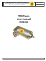
1
CRD absolute encoder with PROFIsafe interface CRD/S2 model series with SIL2 according to IEC 61508 Accompanying data sheet: CRD 11947 CRD 11948 HE 10 / 2012 PROFIsafe User manual CRD/S2 TWK-ELEKTRONIK GmbH · PB. 10 50 63 · D-40041 Düsseldorf · Tel.: +49/211/63 20 67 · Fax: +49/211/63 77 05 · [email protected] · www.twk.de COPYRIGHT: The Operating Instruction CRD 11948 is owned by TWK-ELEKTRONIK GMBH and is protected by copyright laws and international treaty provisions. © 20010 by TWK-ELEKTRONIK GmbH POB 10 50 63 40041 Düsseldorf Germany Tel. +49/211/96117-0 Fax +49/211/96117-99 [email protected] www.twk.de CRD 11948 HE / Page 2 Table of contents Table of contents 1. Safety instructions............................................................................................................................5 1.1 Scope of validity............................................................................................................................5 1.2 Documentation..............................................................................................................................5 1.3 Proper use....................................................................................................................................5 1.4 Commissioning.............................................................................................................................5 2. General information on the CRD/S absolute encoder with SIL2 according to IEC 61508..........6 3. Specifications for meeting the safety standard.............................................................................7 4. Installation instructions for PROFIsafe...........................................................................................8 5. Monitoring functions for safety-relevant use...............................................................................10 5.1 Error type overview table............................................................................................................10 5.2 Description of error types............................................................................................................ 11 5.2.1 Position................................................................................................................................................. 11 5.2.2 Speed................................................................................................................................................... 11 5.2.3 MSA...................................................................................................................................................... 11 5.2.4 Parameters........................................................................................................................................... 12 5.2.5 F parameters........................................................................................................................................ 12 5.2.6 F parameter CRC................................................................................................................................. 12 5.2.7 Configuration........................................................................................................................................ 12 5.2.8 Preset................................................................................................................................................... 13 5.2.9 Error..................................................................................................................................................... 13 6. Data exchange function (DDLM_Data_Exchange).......................................................................14 6.1 Data format of I/O data...............................................................................................................14 6.2 Positions data.............................................................................................................................14 6.3 Speed.........................................................................................................................................14 6.4 Set reference value (preset).......................................................................................................15 7. Configuration (DDLM_Chk_Cfg)....................................................................................................16 8. Programming parameters for absolute encoders with PROFIsafe (DDLM_Set_Prm)..............17 8.1 Standard parameters..................................................................................................................17 8.1.1 Bus-specific parameters....................................................................................................................... 17 8.1.2 Encoder parameters............................................................................................................................. 17 8.1.2.1 Overview........................................................................................................................................... 17 8.1.2.2 Description of encoder parameters................................................................................................... 18 8.2 F parameters (version 1.30).......................................................................................................19 8.2.1 Overview.............................................................................................................................................. 19 8.2.2 Description of encoder parameters...................................................................................................... 19 CRD 11948 HE / Page 3 Table of contents 9. Diagnostic messages (DDLM_Slave_Diag)...................................................................................21 9.1 Diagnostic overview....................................................................................................................21 9.2 Diagnostic description.................................................................................................................22 9.2.1 Standard diagnostic information (Octet 1-6)......................................................................................... 22 9.2.2 Extended header byte (Octet 7)........................................................................................................... 22 9.2.3 Alarm messages (Octet 8).................................................................................................................... 22 9.2.4 Operating status (Octet 9).................................................................................................................... 22 9.2.5 Encoder Typ (Octet 10)........................................................................................................................ 22 9.2.6 Resolution (Octet 11-14)...................................................................................................................... 22 9.2.7 Measuring range (Octet 15, 16)........................................................................................................... 22 9.2.8 Additional alarm messages (Octet 17)................................................................................................. 22 9.2.9 Supported alarm messages (Octet 18,19)........................................................................................... 22 9.2.10 Warning messages (Octet 20,21)....................................................................................................... 23 9.2.11 Supported warnings (Octet 22,23)...................................................................................................... 23 9.2.12 Profile version (Octet 24,25)............................................................................................................... 23 9.2.13 Software version (Octet 26,27)........................................................................................................... 23 9.2.14 Operating time (Octet 28-31).............................................................................................................. 23 9.2.15 Offset value (Octet 32-35).................................................................................................................. 23 9.2.16 Manufacturer offset value (Octet 36-39)............................................................................................. 23 9.2.17 Resolution (Octet 40-43).................................................................................................................... 23 9.2.18 Total measuring steps (Octet 44-47).................................................................................................. 24 9.2.19 Serial number (Octet 48-57)............................................................................................................... 24 9.2.20 Octet 58,59......................................................................................................................................... 24 9.2.21 Manufacturer-specific diagnosis (Octet 60-63) .................................................................................. 24 10. Simatic Step7 with distributed safety..........................................................................................25 10.1 Integration of the TWK profibus absolute encoder...................................................................25 10.1.1 Installation of the GSD file.................................................................................................................. 25 10.1.2 Selection of the TWK absolute encoder from the Step7 hardware catalogue.................................... 25 10.1.3 Allocation of the profibus address...................................................................................................... 26 10.1.4 Setting the I/O addresses (S7 addresses)......................................................................................... 27 10.1.5 Parameterisation of the absolute encoder.......................................................................................... 27 10.1.6 Setting the F paramters...................................................................................................................... 28 10.1.7 Setting the diagnostic address........................................................................................................... 28 10.2 Example programme................................................................................................................29 10.3 General notes regarding the PROFIsafe programme...............................................................34 11. Scope of delivery...........................................................................................................................36 12. Literature........................................................................................................................................36 Appendix A: Absoute encoder terms................................................................................................36 CRD 11948 HE / Page 4 1. Safety instructions 1. Safety instructions 1.1 Scope of validity This user manual applies exclusively to the following rotary encoders with PROFIsafe interface: - CRDxx-xxxxRxxxxS2Zxx 1.2 Documentation The following documents must be noted: - The owner's system-specific operating instructions - This user manual - Data sheet number CRD 11947 - The pin assignment enclosed with the device - Installation instruction TZY 10206 enclosed with the device 1.3 Proper use TWK-ELEKTRONIK GmbH's rotary encoders and linear transducers are used to record rotary and linear positions, and make their measured values available as an electric output signal. As part of a system, they must be connected to the downstream electronics and must only be used for this purpose. 1.4 Commissioning •The relevant device must only be set up and operated using this document and the documentation specified in point 1.2. •Protect the device against mechanical damage during installation and operation. •The device must only be commissioned and set up by a specialist electrician. •Do not operate the device outside of the limit values which are specified in the data sheet. •Check all electrical connections before commissioning the system. CRD 11948 HE / Page 5 2. General information on the CRD/S absolute encoder 2. General information on the CRD/S absolute encoder with SIL2 according to IEC 61508 Due to the general spread of the PROFIBUS DP /4/ field bus, only the PROFIsafe-specific extensions are dealt with in this manual. Fundamental and more extensive information on the PROFIBUS DP field bus and PROFIsafe can be obtained from the PNO user organisation (www.profibus.com). The CRD PROFIsafe absolute encoders are designed for direct connection to the PROFIsafe as slave subscribers in accordance with the PROFIsafe Profile for Safety Technology according to No. 3.092 or 3.192 (PNO) /1/. The encoder protocol is structured in accordance with the PROFIBUS Profile for Encoders according to No. 3.062 (PNO) /2/. PROFIBUS-DP according to IEC61158-3 is used as the data transmission medium. The encoder profile is defined in PNO 3.062. Communication is equipped with a ProfiSafe interface developed by Siemens. All example applications refer to the SIMATIC S7 with distributed safety version 5.4. The parameter data for the absolute encoder with PROFIsafe are described in a GSD file. This GSD file has been created separately and can only be applied for CRD/S2. The CRD/S2 absolute encoder is a sensor for measuring the angular position of a rotating shaft and for determining the number of revolutions which have been carried out. Measurement of the angular speed also takes place. The sensor scans a coding disk with the aid of a special opto chip as the dimensional embodiment of the angular position. Ascertainment of the number of revolutions which have been carried out is implemented via an electrically scanned, mechanical transmission. The measured speed value is determined via the cyclically read-in position data. The dimension is digits per 10 ms with a resolution of 12 bits. The speed measurement resolution is independent of the single turn resolution. The following parameters can be programmed: Resolution: Total measuring steps: Code sense: Scaling: 2 to 4096 (8192) steps per revolution 2 to 16,777,216 (33,554,432) steps CW/CCW Encoder programming via the bus can be activated or deactivated using a flag (scaling). The following monitoring functions are implemented for safety-relevant use: 1.Monitoring of the controller function (memory test and CRC parameter test) 2.Programme sequence monitoring (implementation of inverse functions for the safety-critical programme func- tions). 3.Monitoring of the single turn position via movement detection in which impulses are generated from the position changes. 4.Monitoring of the revolution counter via parallel counting of the single turn zero transitions and comparison with multi-turn scanning. 5.Clock pulse and timer monitoring via a redundant clock pulse generator. 6. Functional monitoring of the FPGAs used to determine the position via a toggle bit which is triggered in the event of controller access. 7.Overvoltage and undervoltage monitoring. 8.Current monitoring for the position-determining light emitting diodes. 9.Supply current overcurrent protection. In deviation from profile definition PNO 3.062, the encoder with Profisafe only has class 2 functionality. The definitions of the error statuses, which are displayed in the „Manufacturer-specific diagnosis“ diagnostic object, Octet 60-63, also deviate from the above mentioned profile CRD 11948 HE / Page 6 3. Specifications for meeting the safety standard 3. Specifications for meeting the safety standard 1.Observance of data sheet CRD11947 and the CRD11948 manual. 2.Maximum permissible rotational speed for applications with SIL2 classification 1000 rpm. 3.Use of an evaluation unit which supports the Profisafe protocol. 4.Evaluation of the F status and the encoder-specific diagnostic data. 5.Connection of a profibus cable in compliance with the standards /3/,/8/. CRD 11948 HE / Page 7 4. Installation instructions for PROFIsafe 4. Installation instructions for PROFIsafe Fundamental characteristics of the transmission technology (RS 485) o Network topology: Linear bus, terminating resistors for bus termination Stub lines are only permissible with baud rates < 1.5 MBit/s o Shielded, twisted pair cable Line: o Number of stations: 32 stations in each segment without repeaters Can be extended to 126 with repeaters. Wiring and bus termination for PROFIBUS-DP (note: 9-pin sub-D connector) VP (6) Station 1 Station 2 390 Ω RxD/TxD-P (3) Data line B (3) RxD/TxD-P DGND (5) RxD/TxD-P (3) (5) DGND VP (6) 220 Ω (6) VP RxD/TxD-N (8) Data line A (8) RxD/TxD-N RxD/TxD-N (8) Shield/ PE 390 Ω Terminating resistance of the bus Connection DGND (5) Transmission length depending on transmission speed for cable type A Baud rate [kBaud] 9.6 19.2 93.75 187.5 500 1500 12,000 Transmission length [m] 1200 1200 1200 1000 400 200 100 Cable type A specifications: Characteristic impedance: Capacitance per unit length coating: Loop resistance: Core diameter: Core cross-section: 135...165 Ω < 30 pF/m 110 Ω/km 0.64 mm > 0.34 mm² Also see: Installation Guideline for PROFIBUS -FMS/DP (Nr. 2.111/2.112 - PNO) /3/ and Profibus Installation Guideline (Nr. 8.021) /8/ CRD 11948 HE / Page 8 4. Installation instructions for PROFIsafe Installation of the absolute encoder with connecting cap The connecting cap for triple connection technology is a T coupler which is installed in the PROFIBUS. The connecting cap must be mounted on the absolute encoder in de-energised condition. There are three cable glands, which are sub-divided as follows: o o o M12x1.5: Voltage supply for the absolute encoder (24 VDC) M16x1.5: Bus in (receive/transmit data A,B) M16x1.5: Bus out (receive/transmit data A‘,B‘) The absolute encoder is connected via the 15-pin SUB-D connector. In the event of an error, the encoder can be replaced without time-consuming installation. The connecting cap is disconnected from the absolute encoder by unscrewing 2 fastening screws. (Note: O-ring seal) The station/subscriber address is set via the DIP switches in the connecting cap. The address range lies between 1 and 126 (default address: 123). Attention! The profibus address in the connecting cap must correspond to the F parameter „F_Dest_Add“ (see Chapter 8.2). The terminating resistors are set via the 10-fold DIP switch (9,10) in the connecting cap; if necessary, these can be activated as line termination. Sub D connector 15 pin socket LED status displays Connection terminal 1 DIP switches UB ON + UB - SRD C Err TWK-ELEKTRONIK OFF DÜSSELDORF Connection terminal 2 (PROFIBUS) A B A’ B’ Fastening screw M3 (captive) DIP switches - address setting/terminating resistors Switch 1 2 3 4 5 6 ON = 1 LSB OFF = 0 Address can be set from 1- 126 (Default address: 123) 7 8 MSB n.c. 9 10 Terminating resistors: On Terminating resistors: Off Status LEDs UB – operating voltage SRD – data transfer C - class 2 Error message UB SRD C Err Description of error types see Chapter 5. CRD 11948 HE / Page 9 5. Monitoring functions for safety-relevant use 5. Monitoring functions for safety-relevant use The additionally implemented error types for achieving safety level SIL2 according to IEC 61508 are described in the following. For implementation purposes, extensive modifications have been carried out to the hardware and software in comparison with the basic CRD model absolute encoder with PROFIBUS interface. Error output is carried out via the connecting cap's LEDs, via the profibus diagnostic data (standard and manufacturerspecific diagnosis) (see Chapter 9.2) and via the F status. The bits which are set in the profibus diagnostic data and in the F status are specified in the "Reaction" column. 5.1 Error type overview table Error Position Cause of error Single turn array illumination faulty Impermissible difference between movement detection and position Difference between multi-turn counter (software) and multi-turn scanning Reaction LEDs* UB SRD C Err EXT_Diag Flag = 1 Manufacturer Diag: PositionError F_Status: Device_Fault = 1 FV_activated = 1 on off off on Overvoltage at the supply input Speed Impermissible difference between timer controller and external timer EXT_Diag Flag = 1 Manufacturer Diag: SpeedError F_Status: Device_Fault = 1 FV_activated = 1 on off off on MSA Toggle bit error FPGA EXT_Diag Flag = 1 Manufacturer Diag: MSAError F_Status: Device_Fault = 1 FV_activated = 1 on off off on Parameter Error in parameter message on off on on Error in the standard parameters EXT_Diag Flag = 1 Manufacturer Diag: ScalingError Diag.Prm_Fault = 1 Diag.Station_Not_Ready = 1 Error in the parameter message Manufacturer Diag: F Parameter on off/ on off/ on on Manufacturer Diag: F Parameter CRC on off/ on off/ on on Configuration Master and slave configurations differ Diag.Cfg_Fault = 1 on on off on Preset Incorrect preset value EXT_Diag Flag = 1 Manufacturer Diag: PresetError F_Status: FV_activated = 1 on off off on Internal Incorrect programme sequence Stop controller LED: Flashing code 1 CRC Error ROM Stop controller LED: Flashing code 2 F parameter F parameter faulty F parameter CRC CRC error in the F parameters RAM/XRAM Error Stop controller LED: Flashing code 3 Initialization sensor Stop controller LED: Flashing code 4 CRC EEPROM Stop controller LED: Flashing code 5 Error in the sensor, parameter access has failed Stop controller LED: Flashing code 6 Connecting cap expander error Stop controller LED: Flashing code 7 *UB – operating voltage, SRD – data transfer, C - class 2, Err – error message CRD 11948 HE / Page 10 5. Monitoring functions for safety-relevant use 5.2 Description of error types 5.2.1 Position The position and speed data cannot be used. Causes: - Single turn monitoring scanning error - Error in the transmission diode unit - Difference between multi-turn scanning and multi-turn counter - FPGA error - Overvoltage at the supply voltage input - Rotational speed too high Actions: - Device_Fault = 1 - FV_activated = 1 - ExtDiag Flag = 1 - Manufacturer-specific diagnosis = position error (see Octet 60-63) - Light emitting diodes: Error on UB SRD SRD off Class off Remedy: - Reduce the rotational speed to below the maximum value specified in the data sheet. - Check the supply voltage. This must lie within the limits specified in the data sheet. C Err C Err 5.2.2 Speed The position data are OK. Speed measurement is defective. Causes: - Impermissible difference between controller timer and external timer Actions: - Device_Fault = 1 - FV_activated = 1 - ExtDiag Flag = 1 - Manufacturer-specific diagnosis = speed error (see Octet 60-63) - Light emitting diodes: Error on SRD off Class off UB SRD 5.2.3 MSA The position and speed data are presumably incorrect. The Multi-turn Single turn Array (MSA) is defective. Causes: - Toggle flag does not function correctly Actions: - Device_Fault = 1 - FV_activated = 1 - ExtDiag Flag = 1 - Manufacturer-specific diagnosis = MSA error (see Octet 60-63) - Light emitting diodes: Error on SRD off Class off UB SRD C Err CRD 11948 HE / Page 11 5. Monitoring functions for safety-relevant use 5.2.4 Parameters The encoder does not start up. Causes: - Error in standard parameter parameterisation Actions: - ExtDiag Flag = 1 - Manufacturer-specific diagnosis = scaling error (see Octet 63-66) - Light emitting diodes: Error on SRD off Class on Remedy: - Set permissible values for the standard parameters. UB SRD C Err 5.2.5 F parameters The encoder achieves data exchange status if no further error is present. Causes: -The transferred F parameters are faulty Actions: - Manufacturer-specific diagnosis = F parameter error (see Octet 60-63) - Light emitting diodes: Error on UB SRD C Err SRD off/on Class off/on Remedy: - Set permissible values for the F parameters. A typical error is an incorrect slave address (F_Dest_Add) 5.2.6 F parameter CRC The encoder achieves data exchange status if no further error is present. Causes: - The transferred F parameter checksum (CRC1) is incorrect Actions: - Manufacturer-specific diagnosis = F parameter CRC error (see Octet 60-63) - Light emitting diodes: Error on UB SRD off/on Class off/on SRD C Err SRD C Err 5.2.7 Configuration The encoder does not start up. Causes: - Difference between master configuration and slave configuration. Actions: - Light-emitting diodes: Error on SRD off/on Class off/on Remedy: - Transfer a correct configuration message (see Chapter 7) UB CRD 11948 HE / Page 12 5. Monitoring functions for safety-relevant use 5.2.8 Preset The encoder is fully operable. Causes: - The preset value lies outside of the set total measuring steps - The scaling flag in the operating mode byte is deactivated. Actions: - FV_activated = 1 - Manufacturer-specific diagnosis = preset value error (see Octet 60-63) - Light emitting diodes: Error on UB SRD C Err SRD off Class off Remedy: - Transfer a pre-set value which lies between 0 and the total measuring steps -1. - Before setting the pre-set value, the "scaling function" bit must be set to "enable". (see Chapter 6.4) 5.2.9 Error The micro-controller of the encoder stops all actions. A flashing code for the cause of the error is output. Number of flashes (Period approx. 1 s) LED: Flashing code Error cause Flashing code 1 Programme sequence error 1 Flashing code 2 CRC Error ROM 2 Flashing code 3 RAM/XRAM memory error 3 Flashing code 4 Sensor initialisation error 4 Flashing code 5 EEPROM memory error 5 Flashing code 6 Parameter access has failed 6 Flashing code 7 Connecting cap expander error 7 Remedy: - Please send the device for repair back to TWK. CRD 11948 HE / Page 13 6. Data exchange function (DDLM_Data_Exchange) 6. Data exchange function (DDLM_Data_Exchange) Input data are data which are transmitted from the slave subscribers to the master (actual position value -> master). Reference value control (see below) is listed here as an example of output data; in this case, the master transmits data to the slave (absolute encoder). 6.1 Data format of I/O data Input data: Slave to host Octet 1 Octet 2 MSB Octet 3 Octet 4 Position Data Octet 5 LSB MSB Octet 6 Speed Octet 7 Octet 8 Octet 9 Octet 10 Octet 9 Octet 10 F-Data LSB Definition of F-Data can be found in /1/. Output data: Host to slave Octet 1 Octet 2 MSB* Octet 3 Octet 4 Preset Value Octet 5 LSB MSB Octet 6 Dummy Octet 7 Octet 8 LSB F-Data * Preset control via bit 31: 1/0 6.2 Positions data The position value is output as a 32-bit unsigned integer value in Motorola format (Big-Endian). Octet 1 7 6 5 4 3 Octet 2 2 1 0 7 6 5 4 Octet 3 2 1 0 7 6 5 4 3 Octet 4 1 0 7 6 5 4 3 2 1 0 31 30 29 28 27 26 25 24 23 22 21 20 19 18 17 16 15 14 13 12 11 10 9 8 7 6 5 4 3 2 1 0 0 0 0 0 0 0 0 3 2 25 Bit Position Data CRDxx-8192R4096S2Zxx 0 0 0 0 0 0 0 0 24 Bit Position Data CRDxx-4096R4096S2Zxx 6.3 Speed The speed value is determined via the cyclically read-in of the position data. In the standard version, the dimension is steps per 10 ms. The speed measurement resolution is independent of the resolution set for the position value (resolution parameter). It is always based on a resolution of 4096 steps per revolution. The steps/10 ms unit can be converted to rpm as follows: v [steps/10ms] x 6000 u= v = speed in steps/10ms 4096 steps u = speed in rpm The speed value is output as a 16-bit signed integer value in Motorola format (Big-Endian). The following applies to the prefix: Clockwise direction of rotation* (cw) positive Counter-clockwise direction of rotation* (ccw) negative This is independent of the code direction set for the position value (code sequence parameter) Octet 5 7 6 5 4 3 Octet 6 1 0 7 6 5 4 3 2 1 0 15 14 13 12 11 10 9 2 8 7 6 5 4 3 2 1 0 Speed *Viewing direction towards the shaft CRD 11948 HE / Page 14 6. Data exchange function (DDLM_Data_Exchange) 6.4 Set reference value (preset) The set reference value function should only be carried out when the absolute encoder shaft is stationary! In order to compare machine position values and the absolute position of the absolute encoder, setting the reference value is unavoidable in certain cases. The reference value is the position value which is displayed in the reference point. The user must note the fact that the reference value must lie within the range 0 to (total measuring steps - 1). In particular, this must be taken into consideration when changing the total measuring steps. The reference value is transferred in data exchange mode by setting bit 31/octet 3. The reference value can only be set when scaling is activated (see Chapter 8.1)! Octet 1 7 6 5 4 3 Octet 2 2 1 0 7 6 5 4 3 2 1 0 31 30 29 28 27 26 25 24 23 22 21 20 19 18 17 16 15 14 13 12 11 10 9 8 7 6 5 4 3 2 1 0 0/1 0 0 0 0 0 0 0 5 4 3 2 1 0 7 6 5 4 3 Octet 4 0 0 0 0 0 0 0 6 Octet 3 1 0/1 7 2 25 Bit Preset Value CRDxx-8192R4096S2Zxx 24 Bit Preset Value CRDxx-4096R4096S2Zxx After receiving this message, an offset value (from the current actual position value and the reference value) is calculated by the encoder. If the output actual position value is identical to the reference value, bit 31/octet 1 can be reset by the master, as preset mode is terminated. The timing diagrams are specified in a separate TY sheet. After bit 31 has been reset, the absolute encoder operates in „normal operating mode“. On inputting a faulty preset value, control bit 31 must be set to zero before inputting the correct preset value in order to rectify the error. After setting control bit 31 to 1, the preset value can then be set again. CRD 11948 HE / Page 15 7. Configuration (DDLM_Chk_Cfg) 7. Configuration (DDLM_Chk_Cfg) Only Class 2 encoders are supported. Class 2 - devices are programmable via the Profibus (set reference value (preset)). The data format is: 10 byte input data and 10 byte output data. The identification is: 0xC8,0x89,0x89,0x03,0x03 ,0x03,0xA,0x03,0x03,0x03,0x0A. Configuration function (DDLM_Chk_Cfg) Selection Identifier byte Data Class 2 0xC8,0x89,0x89,0x03,0x03,0x03, 10 Byte Input data 0xA,0x03,0x03,0x03,0x0A Data format Encoder position Octet 1/Bit 7: MSB Octet 4/Bit 0: LSB Velocity signal Octet 5/Bit 7 MSB Octet 6/ Bit 0: LSB F-Data Octet 7-Octet 10 10 Byte Output data Preset value Octet 1/Bit 7: Preset Control Octet 1/Bit 0: MSB Octet 4/ Bit 0: LSB Dummy Octet 5/Bit 7: MSB Octet 6/Bit 0: LSB F-Data Octet 7-Octet 10 CRD 11948 HE / Page 16 8. Programming parameters for absolute encoders with PROFIsafe 8. Programming parameters for absolute encoders with PROFIsafe (DDLM_Set_Prm) The parameterisation data are sub-divided into standard parameters (bus-specific parameters and manufacturerspecific parameters) and the F parameters. Octet 1-7 Bus-specific parameters Standard parameters Octet 8-29 Octet 0-13 Encoder-specific parameters F-parameters 8.1 Standard parameters 8.1.1 Bus-specific parameters Octet Data type Description Default 1 BYTE Station status - 2 BYTE WD_Fact_1 - 3 BYTE WD_Fact_2 - 4 BYTE Min. Station Delay Responder (min TSDR) - 5/6 WORD Ident_Number 7 BYTE Group_Ident 0x1962 0 The definition of the bus-specific parameters can be found in /4/ 8.1.2 Encoder parameters 8.1.2.1 Overview Octet Data type Description Default 8 BYTE Reserved 9 BYTE Operating mode 10 - 13 LONG Single turn resolution 4096 (8192) 14 - 17 LONG Total measuring steps 16.777.216 (33.554.432) 18 - 25 STRING 26 - 29 LONG 0 0x08 Reserved for profile 0 Reserved for manufacturer 0 The values in brackets represent the rotary encoders with 25-bit total measuring steps (CRDxx-8192R4096S2Zxx). CRD 11948 HE / Page 17 8. Programming parameters for absolute encoders with PROFIsafe 8.1.2.2 Description of encoder parameters Octet 11: Operating mode Bit Nr. 0 1-2 3 4-7 Default Description Parameter Range of values Code sequence 0: clockwise (cw) clockwise 1: counter clockwise (cw) (ccw) Ascending values on rotation clockwise (cw) or counter-clockwise (ccw). (Viewing direction towards the shaft) 0: disabled 1: enabled Must be set to "enabled" to change the reference value, resolution and total measuring steps. not used Scaling function status enabled not used Octet 12 - 31: Parameter Range of values Default Description 12 - 15 Singleturn resolution 1 - 4096 (8192) 4096 To change, the "scaling function status" parameter must be set to "enabled". 16 - 19 Total measuring steps 1 - 16.777.216 (33.554.432) 16.777.216 To change, the "scaling function status" parameter must be set to "enabled". 20 - 27 Reserved for profile 28 - 31 Reserved for manufacturer Octet Nr. Note: It must be noted that the calculation of the number of revolutions is carried out in 2n powers internally within the encoder. Regardless of this requirement, the user may programme the desired total measuring steps and the desired resolution in accordance with the application. During calculation, the absolute encoder accesses the next highest 2n power if required. In this case, the values are designated as the actual resolution or as the actual total measuring steps, and are displayed as the output value. Example: Desired total measuring steps: Desired resolution: 20,480 4096 5 Internal absolute encoder calculation 32,768 4096 8 Desired number of resolutions: Actual total measuring steps: Actual resolution: Calculated number of revolutions: (Note: The above mentioned note must be taken into consideration in the event of irreversible operation. In the example which is described, the position 0 is only achieved after 32,767 steps and not, as desired, after 20,479 steps.) CRD 11948 HE / Page 18 8. Programming parameters for absolute encoders with PROFIsafe 8.2 F parameters (version 1.30) 8.2.1 Overview Overview F_Prm_Block F_Parameter End_F_Prm_Block Octet No. Data type 0 BYTE Description GSD-file Block length 0x0E 1 BYTE Command = 0x05 0x05 2 BYTE Slot - 3 BYTE Specifier 0x0A 4 BYTE F_Prm_Flag1 14 5 BYTE F_Prm_Flag2 0 6-7 WORD F_Source_Add - 8-9 WORD F_Dest_Add 123 10-11 WORD F_WD_Time 2000 12-13 WORD F_Par_CRC (=CRC1) 8.2.2 Description of encoder parameters Octet 4: F_Prm_Flag1 Bit No. Parameter name Range of values Default Parameter description 0 F_Check_SeqNr 0 – the sequential No. is not integrated into the CRC 1 – the sequential No. is integrated into the CRC No check The parameter determines whether the sequential number (consecutive number) is taken into consideration in CRC calculation of the F useful data message. 1 F_Check_iPar 0,1 0 0 – individual CRC3 parameters are not integrated into CRC2 1- individual CRC3 parameters are integrated into CRC2 CRC1 – F parameter checksum CRC2 – Process data checksum CRC3 – Individual parameter checksum 2-3 F_SIL 00b - SIL1 01b - SIL2 10b - SIL3 11b - NO SIL SIL2 firmly set SIL 1-3 or No SIL (Safety Integrity Level) according to IEC 61508 (functional safety of safety-related electrical / electronic / programmable electronic systems) 4-5 F_CRC_Length 00b - 3 bytes, V2 mode 01b - 2 bytes, V1 mode 10b - 4 bytes, optionally V1/V2 mode 11b 2 bytes CRC CRC2 check value (from F useful data), V2 mode is not supported 6-7 Not used CRC1 – F parameter checksum CRC2 – Process data checksum CRC3 – Individual parameter checksum CRD 11948 HE / Page 19 8. Programming parameters for absolute encoders with PROFIsafe Octet 5: F_Prm_Flag2 Bit No. Parameter name 0-2 Not used 3-5 F_Block_ID 6-7 F_Par_Version Range of values Default Parameter description F host/F slave relationship Firmly set 00b - V1.30 mode 01b - V2 mode 10b 11b V1.30 mode Parameter version, V2 mode is not supported Default Octet 6-13 Octet Parameter name Range of values Parameter description 6-7 F_Source_Add 1 - 65,534 8-9 F_Dest_Add 1 - 123 123 Must correspond to the address set in the connecting cap (DIP switches)! 10-11 F_WD_Time 1 - 65,534 2000 Monitoring time in the failsafe DP standard slave. Within the monitoring time, a valid, current safety message must be received from the F CPU. (1 – 65,534 ms) 12-13 F_ParCRC (CRC1) 0 - 65,535 Automatically assigned by the SIMATIC manager CRD 11948 HE / Page 20 9. Diagnostic messages (DDLM_Slave_Diag) 9. Diagnostic messages (DDLM_Slave_Diag) 9.1 Diagnostic overview Diagnostic messages DDLM_Slave_Diag Diagnostic octet number Diagnostic function Octet Default Remark 1-6 Standard diagnostic information 01 00hex 02 0Chex 03 00hex 04 01hex Parameterisation via master with address 1 05-06 1962hex ID number CRD Response monitoring activate, bit 2 firmly to 1 Device-related diagnosis 7 Extended header byte 39hex 57 diagnostic bytes 8 Alarm messages 00hex Not supported 9 Absolute encoder operating parameters 08hex CW, scaling on 10 Encoder type 01hex Absolute multiturn encoder 11(MSB)-14(LSB) Resolution 1000hex (2000hex) 4096 (8192) steps/ revolutions 15-16 Measuring range 1000hex 4096 revolutions 17 Additional alarm messages 00hex None 18-19 Supported alarm messages 0000hex None 20-21 Warning messages 0000hex Not supported 22-23 Supported warning messages 0000hex Not supported 24-25 Profile version 0x0101 26-27 Software version xx.xx 28-31 Operating time FFFF.FFFFhex 32-35 Offset value 0000.0000hex 36-39 Manufacturer offset value 0000.0000hex 40 (MSB) - 43 (LSB) Resolution 0000.1000hex 0000.2000hex 44(MSB) - 47 (LSB) Total measuring steps 01.000.000hex 02.000.000hex 48-57 Serial number 2A2A2A2A2A 2A2A2A2A2Ahex 58-59 Reserved 0000hex 60-63 Manufacturer-specific diagnosis 00000000hex Not supported Not supported Defined during run time CRD 11948 HE / Page 21 9. Diagnostic messages (DDLM_Slave_Diag) 9.2 Diagnostic description Explanations regarding the diagnostic information: 9.2.1 Standard diagnostic information (Octet 1-6) For a detailed description, see IEC 61158 Type 3 and IEC 61784, PROFIBUS DP Specification /4/ (Note: Octet 5,6: Manufacturer identification: 1962hex) The manufacturer identification is stored in the PNO and identifies the subscriber as a TWK absolute encoder. 9.2.2 Extended header byte (Octet 7) The length of the extended diagnostic bytes including the header is specified in the diagnostic header (Octet 7). (Class 2 absolute encoder: 39hex = 57d -> 6 (standard diagnosis) + 1 (Octet 7)+ 56 (Octet 8-63) = 63 diagnosis bytes) 9.2.3 Alarm messages (Octet 8) No alarm messages are output here. All error messages are output in the manufacturer-specific diagnostic range (octets 63-66) 9.2.4 Operating status (Octet 9) Mirroring of the parameter operating mode 9.2.5 Encoder Typ (Octet 10) The byte is set firmly to 0x01, i.e. "absolute multiturn encoder" 9.2.6 Resolution (Octet 11-14) Maximum value for the parameter resolution. Parameter Resolution Diagnosis Octet 11 12 13 14 Bit MSB 31-24 23-16 15-8 7-0 LSB 9.2.7 Measuring range (Octet 15, 16) The maximum possible number of revolutions, specified via the resolution of the multi-turn section. Depiction in hexadecimal form, e.g. 4096 revolutions = 1000hex. Parameter Measuring range Diagnosis octet 15 16 Bit MSB 15-8 7-0 9.2.8 Additional alarm messages (Octet 17) Not currently assigned. 9.2.9 Supported alarm messages (Octet 18,19) No alarm messages supported. CRD 11948 HE / Page 22 9. Diagnostic messages (DDLM_Slave_Diag) 9.2.10 Warning messages (Octet 20,21) These functions are not supported at present. 9.2.11 Supported warnings (Octet 22,23) These functions are not supported at present. 9.2.12 Profile version (Octet 24,25) Parameter Profile version Diagnosis Octet 24 25 Definition Revisionsnummer Index Actuel encoder profile version: 1.1. 9.2.13 Software version (Octet 26,27) Parameter Software version Diagnosis Octet 26 27 Definition Revisionsnummer Index Actual software version, 3.3. 9.2.14 Operating time (Octet 28-31) This function is not supported at present. The operating time is set to FFFF FFFFhex as default according to the encoder profile. 9.2.15 Offset value (Octet 32-35) The offset value is the value for the shift in the zero point after setting the preset value. Parameter Offset value Diagnosis octet 32 33 34 35 Bit MSB 31-24 23-16 15-8 7-0 LSB 9.2.16 Manufacturer offset value (Octet 36-39) Not supported at present. 9.2.17 Resolution (Octet 40-43) The resolution set by parametration. Parameter Resolution Diagnosis Octet 40 41 42 43 Bit MSB 31-24 23-16 15-8 7-0 LSB CRD 11948 HE / Page 23 9. Diagnostic messages (DDLM_Slave_Diag) 9.2.18 Total measuring steps (Octet 44-47) Set total measuring steps incremented to the next highest power of two. In this regard, also see the note under Chapter 8.1.2.2 Parameter Total measuring steps Diagnosis Octet 44 45 46 47 Bit MSB 31-24 23-16 15-8 7-0 LSB 9.2.19 Serial number (Octet 48-57) This parameter is not supported at present. 9.2.20 Octet 58,59 Reserved 9.2.21 Manufacturer-specific diagnosis (Octet 60-63) Overview Manufacturerspecific diagnosis octet No. Bit Error 60 0 F parameter CRC 1 F parameter 2-7 Not supported 61 Not used 62 Not used 63 0 Scaling 1 Preset value 2 Position 3 Speed 4 MSA 5-7 Not supported A detailed description of the error can be found in Chapter 5! CRD 11948 HE / Page 24 10. Simatic Step7 with distributed safety 10. Simatic Step7 with distributed safety This chapter explains the procedure for integrating the TWK absolute encoder into the profibus of a Siemens S7 control system. The documentation is based on Step 7 with distributed safety version 5.4. 10.1 Integration of the TWK profibus absolute encoder Prerequisites: You have configured your hardware in accordance with the structure of your control system and have installed a profibus sub-network. 10.1.1 Installation of the GSD file - Close all projects in the hardware configuration. - Insert the CD-ROM provided by TWK into your drive. - In the hardware configuration, select Install GSD files under Options. - Set your CD-ROM drive as the directory and install the GSD file Safec24s.GSD for the 24-bit absolute encoder or Safec25s.GSD for the 25-bit absolute encoder. - The absolute encoder symbol is also installed automatically. 10.1.2 Selection of the TWK absolute encoder from the Step7 hardware catalogue - After opening the hardware catalogue, you will find the encoder Safe CRD/24S or Safe CRD/25S under Profibus-DP, Additional Field Devices, Encoders. - Now open your project, mark the bus and integrate the absolute encoder into the bus by double-clicking onto the corresponding line of the hardware catalogue. - After selecting the profibus address (see Chapter 10.1.3), drag the Safe_CRD... module to slot 1 of the module list. Please select your SAFE CRD... encoder here. CRD 11948 HE / Page 25 10. Simatic Step7 with distributed safety 10.1.3 Allocation of the profibus address Please specify the address set in the connecting cap via the DIP switches here. In the Subnet field, additionally select your planned profibus and exit the window with OK. Then drag the Safe_CRD ... module to slot 1 of the module list. The absolute encoder should then appear as follows in your project planning. Double-click to allocate the diagnostic address Double-click to set the I/O addresses for parameterisation The DP ID value results from the configuration, which is firmly set in the case of the Profisafe absolute encoder. The I/O address values are default values, which vary depending on the control system. CRD 11948 HE / Page 26 10. Simatic Step7 with distributed safety 10.1.4 Setting the I/O addresses (S7 addresses) Double-clicking onto the „Slot 1“ line opens up the Properties – DP slave window with the Address / ID, Parameter Assignment and PROFIsafe registers. The addresses for the absolute encoder, under which this is to be addressed in the S7, must be assigned under output and input in the Address / ID register. 10.1.5 Parameterisation of the absolute encoder Via the Parameter Assignment register, the following window, in which the characteristics of the absolute encoder can be defined, is accessed. (see Chapter 8.1) CRD 11948 HE / Page 27 10. Simatic Step7 with distributed safety 10.1.6 Setting the F paramters Via the PROFIsafe register, the following window, in which the F parameters can be defined, is accessed. (see Chapter 8.2) Note: Under certain circumstances, Step7 may show a different default value for F_Dest_Add here. This must be set to the set profibus address! 10.1.7 Setting the diagnostic address So that the absolute encoder‘s diagnostic area can be accessed within the S7 programme, it is necessary to assign a specific S7 diagnostic address to it. This may lie within the entire periphery area of the control system. It does not therefore occupy any input/output addresses. The Properties – DP slave window with the General register appears by double-clicking onto the encoder symbol. You can now set the diagnostic address and confirm it with OK. CRD 11948 HE / Page 28 10. Simatic Step7 with distributed safety 10.2 Example programme The following example shows how to access the position value and the F periphery DB of the Profisafe absolute encoder in the safety programme. Setting a preset value is also demonstrated. Only the programming steps which refer to the TWK absolute encoder are shown here. Knowledge regarding the programming and sequence of the failsafe S7 programme is assumed. As an introduction to failsafe programming, we recommend „SIMATIC S7 Distributed Safety - Getting Started“ /7/ and „SIMATIC S7 Distributed Safety – Project Planning and Programming“ /6/. Note: TWK-ELEKTRONIK GmbH does not undertake to provide any guarantee for the error-free function of the example programmes shown here! Devices required to operate the example programme - F CPU with profibus interface - Standard input assembly - Standard output assembly - Profisafe CRD absolute encoder - Step7 as of V5.4 + S7 distributed safety as of version V5.4 Hardware structure of the example programme Assigned I/O addresses: Input assembly DI32 Bytes 0...4 Output assembly DO32 Bytes 4...7 Absolute encoder Bytes 100...109 CRD 11948 HE / Page 29 10. Simatic Step7 with distributed safety F periphery DB On translation of the hardware configuration, an F periphery DB is generated for the absolulute encoder, as for each other Profisafe subscriber. In our example, it bears the automatically assigned, symbolic name „F00100_200“. The F periphery DB enables access to the control and status byte of the profisafe protocol. It has the following appearance: In the example programme, the variables „ACK_REQ“ and „ACK_REI“ are used for reintegration and „DIAG“ and „QBAD“ for diagnosis. For a detailed description of the F periphery DB, refer to „SIMATIC S7 Distributed Safety – Project Planning and Programming“ /6/. Programming Access to the profisafe absolute encoder is carried out in an F programme module (here FB100), which must be called up in an F call-up module F CALL. Calling the FB100 in the F CALL is not described here. The preset value and preset bit compilation is contained in a standard module (here OB1). This is carried out here under the prerequisite that setting the preset is not a safety-relevant function. Note: The decision regarding whether setting the preset value is a safety-relevant function must be made depending on the application. Important for the fail safe operation of the encoder are: reintegration after communication or F periphery errors, as depicted in FB100 NW1 and NW2, evaluation of the failsafe status as depicted in FB100 NW3 and the evaluation of the diagnostic data, as depicted in OB1 NW4. Note:Access to the profisafe absolute encoder‘s I/O data in the safety programme is only possible on a word by-word basis. Inputs and outputs used in the programme: E 0.0 E 0.1 EW 100 EW 102 A 4.0 A 5.0 AW 100 AW 102 Acknowledgement for reintegration Set preset High word of the encoder position value Low word of the encoder position value „Acknowledgement required“ display Failsafe status display High word of the encoder preset value Low word of the encoder preset value CRD 11948 HE / Page 30 10. Simatic Step7 with distributed safety Attention: The OB1 and FB100 modules shown in the following only represent part of the safety programme and only refer to the example structure‘s hardware. The creation of a complete and error-free safe ty programme is the sole responsibility of the user. The OB1 and FB100 modules are contained on the supplied CD in the „S7_Bsp“ directory in archive file „TwkBspS2. zip“. The password for the FB100 is „twk“. The non-secure signals in the safety programme (FB100 in this case) are shown in red here. CRD 11948 HE / Page 31 10. Simatic Step7 with distributed safety CRD 11948 HE / Page 32 10. Simatic Step7 with distributed safety FB100 help flag: CRD 11948 HE / Page 33 10. Simatic Step7 with distributed safety 10.3 General notes regarding the PROFIsafe programme Due to the very complex scope for F programme project planning and programming, reference must be made to the documentation from Siemens at this point. SIMATIC S7 Distributed Safety – Project Planning and Programming, Programming and Operating Manual (A5E00109536-03) /6/ and SIMATIC S7 Distributed Safety Getting Started /7/. The sequences required for the PROFIsafe application are listed briefly in the following. PROFIsafe CPU parameters Access to the F CPU is protected against unauthorised access via a password prompt. PROFIsafe OB 35 The safety programme is acessed by calling F CALL; this takes place directly in an OB, e.g. OB 35. In a wake-up alarm OB, the safety programme is called up and run through at fixed intervals of time. CRD 11948 HE / Page 34 10. Simatic Step7 with distributed safety Processing the F sequence module To facilitate handling, a safety programme consists of F sequence modules. These consist of: - An F call module F CALL - An F programme module F-PB (this is an F-FB/F-FC, which you assign to the F CALL) - Poss. further F-FBs/F-FCs - One or more F-DBs - F periphery DBs - F library F modules - F system modules (F-SBs) - Automatically generated F modules Generating and downloading the PROFIsafe programme Finally, the PROFIsafe programme has to be generated and loaded into the CPU. CRD 11948 HE / Page 35 11. Scope of delivery 12. Literature Appendix A: Absolute encoder terms 11. Scope of delivery The scope of delivery includes: - Absolute encoder with PROFIsafe interface - Pin assignment TY XXXXX (depending on the device variant) - CD-ROM with GSD file and user manual in PDF format 12. Literature /1/ PROFIsafe Profile for Safety Technology, Order No. 3.092, PROFIBUS Nutzerorganisation e. V. Haid-und-Neu-Str. 7, D-76131 Karlsruhe, www.profibus.com PROFIsafe Profile for Safety Technology, Order No. 3.192, PROFIBUS Nutzerorganisation e. V. Haid-und-Neu- Str. 7, D-76131 Karlsruhe, www.profibus.com /2/ PROFIBUS Profile for Encoders, Order No. 3.062, PROFIBUS Nutzerorganisation e. V. Haid-und-Neu-Str. 7, D-76131 Karlsruhe, www.profibus.com /3/ Installation Guideline for PROFIBUS DP/FMS, Order No. 2111/ 2.112, PROFIBUS Nutzerorganisation e. V. Haid- und-Neu-Str. 7, D-76131 Karlsruhe, www.profibus.com /4/ IEC 61158 Type 3 and IEC 61784, PROFIBUS DP Specification /5/ PROFIsafe - Environmental Requirements related to PROFIsafe - Profile for Safety Technology on PROFI BUS DP and PROFINET IO (IEC 61784-3-3), Order No. 2.232, PROFIBUS Nutzerorganisation e. V. Haid-und-Neu-Str. 7, D-76131 Karlsruhe, www.profibus.com /6/ SIMATIC S7 Distributed Safety – Project Planning and Programming, Programming and Operating Manual (A5 E00109536-03) /7/ SIMATIC S7 Distributed Safety Getting Started (A5E00320725-01) /8/ Profibus Installation Guideline, Order No. 8.021, PROFIBUS Nutzerorganisation e. V. Haid-und-Neu-Str. 7, D-76131 Karlsruhe, www.profibus.com Appendix A: Absoute encoder terms Parameter Explanation Resolution – steps/360° The resolution specifies the number of steps per revolution (360°). Measuring range The measuring range specifies the maximum number of revolutions. The revolutions must be specified in 2n powers. Total measuring steps The total measuring steps arise as follows: Total measuring steps = resolution x measuring range Code sequence The code sequence specifies the direction of rotation in which the encoder‘s output code corresponds to ascending values. A distinction is made between the following depending on the direction of rotation: CW - clockwise, clockwise direction of rotation CCW - counter clockwise, anti-clockwise direction of rotation (viewed in the direction of the shaft) Reference value The reference value is the value which appears after the preset function as the encoder‘s actual position value. It lies in the range of values from 0 to total measuring steps -1. CRD 11948 HE / Page 36