1
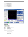
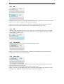
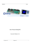
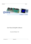
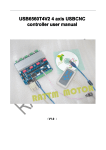
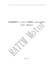
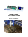
USBCNC PLASMA CONTROL with iCNC600 PLASMA USERMANUAL Document Release 0.1 Published by: Bert Eding Eindhoven The Netherlands Title: Author: Date: USBCNC Plasma user manual Bert Eding Tuesday, 06 January 2015 Document History Version 0.1 Date 15-01-2012 Author B. Eding Comment Initial version for the iCNC600 CPU © Copyright Eding CNC Holding B.V. All rights reserved. Reproduction in whole or in part prohibited without the prior written consent of the copyright owner. Eding CNC BV Plasma Cutting Table of contents Table of contents 3 1 4 2 Introduction 1.1 Context and scope 4 1.2 Definitions, acronyms and abbreviations 5 Torch Height Control 2.1 3 Interface PLASMA – CNC Plasma UI 6 7 9 3.1 General settings for plasma. 3.2 The LEDs 10 3.3 At the top we see 3 buttons: 11 3.4 VACT and VSET: 11 3.5 Corner protection 11 3.6 Controller parameter settings 3.6.1 KP 3.6.2 KD 3.6.3 DEADBAND 3.6.4 Spike filter 3.6.5 Hole Detect 3.6.6 Tracing for checking the behavior 9 11 12 12 12 12 13 13 Eding CNC BV Plasma Cutting 1 Introduction 1.1 CONTEXT AND SCOPE http://www.maschinen-werkzeuge.com/ Hyperterm powermax 105 Eding CNC BV Plasma Cutting 1.2 DEFINITIONS, ACRONYMS AND ABBREVIATIONS CNC Computerized Numerical Control CPU Central Processor Unit, a PCB board with a Processor on it. DXF Drawing Exchange Format) is a CAD data file format developed by Autodesk FIFO First In First Out Buffer HPGL Hewlet Packard Graphical Language GUI/UI Graphical User Interface INTERPRETER A software function that is able to read a text file and execute the commands contained therein. JOBFILE A job is the text file (G code) that will be executed by the interpreter. GUI Graphical User Interface. PWM Pulse Width Modulation G-Code CNC specific language to control the movements and IO of a milling machine. Look Ahead Feed, advanced motion algorithm that ensures minimal machining time. Torch Height Control LAF THC Eding CNC BV Plasma Cutting 2 Torch Height Control The torch height to the work piece determines the quality of the cutting process. The material to cut is not even in height. The voltage across the torch during the process is coupled to the height of the torch. The higher the torch, the higher the voltage will be. Since the torch is coupled to the Z-axis of the CNC machine, the voltage can be kept constant by regulating the height of the torch. This can be done by feeding the (attenuated and isolated) torch voltage to the CNC system. This system will control the height of the Z to keep the voltage constant. Eding CNC BV Plasma Cutting 2.1 INTERFACE PLASMA – CNC Connections Table PLASMA machine. iCNC600 Analog In 5 J9 PIN7 GND Analog In 5 J9 PIN8 Tool Out J11 PIN1 1:50 Voltage divider Plasma ON Relay Hyperterm powermax 105 GND Tool Out J11 PIN1 AUX-IN-1 J5 PIN3 GND AUX-IN-1 J5 PIN5 AUX-OUT-2 J6 PIN9 GND AUX-OUT-2 J6 PIN10 Plasma Voltage (max 300 V) Plasma is ON Feedback Corner (Reduce current Optional) The plasma arc signal is used to control the height of the Z axis. The signal is high voltage (approx. 300V and during ignition even several 1000 volts), it is brought back to a safe voltage using 1 1:50 plasma voltage divider. This divider is already build in into the plasma current source or can be obtained separately from the plasma current source supplier. The signal from the 1:50 voltage divider is connected to analog input 5, see drawing above. The plasma is started using M3, this switches to tool output ON, this can be connected with a relay to the plasma current source. The plasma is on is an output from the plasma source to an input of the CPU indicating that the plasma is ON. This input is optional. The corner output from the CPU is a signal that becomes active when the CNC is reducing velocity in corners. This signal can be used by the plasma source if supported to reduce the plasma current. Eding CNC BV Plasma Cutting THC control sequence 1. 2. 3. 4. 5. 6. 7. 8. 9. At initial position. Move to start position X,Y,Z=pierce height. (Pierce height is equal to ignition height) Switch plasma on (M3) Delay pierce delay. Move Z down to cutting height. Start contour, after Meas/Control delay activate THC controller. Automatically measure voltage and set as set point if required. At end of contour, switch plasma To Retract height. Eding CNC BV Plasma Cutting 3 Plasma UI 3.1 GENERAL SETTINGS FOR PLASMA. Some items need to be setup in the cnc.ini, use notepad or notepad++ similar program to edit the file. This is an example of a working setup: [PLASMA] defaultSetPointVoltage = 135.000000 KPUp = 0.600000 KPDown = 0.600000 KD = 0.050000 deadBand = 0.500000 filterTime = 0.050000 holeDetectVoltage = 25.000000 holeDetectTime = 0.100000 controlDelay = 0.100000 cornerFeedFactor = 0.250000 zMax = 0.000000 zMin = -167.000000 adcOffset = 60.000000 adcMulFactor = 0.1400000 plasmaIsOnInputPortID = 0 plasmaIsCornerOutputPortID = 0 plasmaZDownInputPortID = 0 plasmaZUPInputPortID = 0 plasmaAnalogInputPortID = 5 measuredIsSetpoint = 1 The adcOffset and adcMulfactor determine the relationship between the input voltage read by the processor and the arc voltage. The adcOffset value of 60 resembles the arc voltage where the analog input read is zero. The adcMulFactor is calculated by dividing the range through 1000, in this case, the range 60-200 = 140, so the adcMulFcator = 140/1000 = 0.14. The plasma THC needs: 1. The iCNC600 CPU 2. An external 1:50 voltage divider to be obtained from the plasma source supplier, e.g. Hyperterm. 3. PC with reliable and fast Ethernet, because we will reduce the fife time This improves the dynamic of the THC. So in the standard setup please set the interpolation Time and fifo Time like this: (Standard fifo time = 0.2 Second) 1st setup screen 2nd setup screen Eding CNC BV Its about the left panel. 3.2 THE LEDS THC ON : UP: Down: Corner: Hole: Active: LED is ON when THC function is on. Z is moving UP Z is moving down Corner protect active Hole Detect active On when control is active The THC is active when several conditions are met: THC function is switch on Spindle (PLASMA) is ON Move is G1, G2, G3 without Z Corner protect is not active Hole detect is not active. Plasma Cutting Eding CNC BV Plasma Cutting 3.3 AT THE TOP WE SEE 3 BUTTONS: Spindle ON/OFF (PLASMA) : Switches the plasma ON/OFF THC ON/OFF, switches the THC system ON/OFF. Define Z min, takes current Z position and define that as minimum for the THC, THC will not go lower. It is displayed also in the Z readout gauge in RED. 3.4 VACT AND VSET: VACT button allows to switch the display between the actual plasma voltage or the following error, Vactual - Vset. Auto, when switched on a automatics measurement will take place at the beginning off the cutting sequence. After the Mesa Delay time delay, the voltage is measured and set at set point. This is performed once for a job. VSET shows the actual Voltage setpoint for the THC controller. Meas delay: Sets the delay for automatic measurement and control on. When a cutting move starts, this delay is used before the controller is switched on and the measurement is taken. 3.5 CORNER PROTECTION The Corner VF setting is needed to prevent the torch from diving down at corners. At corners the actual Feed becomes lower, because of this the Plasma voltage gets higher and the THC will start moving the Z DOWN. This is not wanted. So when the Feed is lower than specified percentage here, the THC control will temporarily be disabled, the Z axis will remain at same height. 3.6 CONTROLLER PARAMETER SETTINGS There are a few control parameters, which can be set here, by pressing the button that now showsd KP, next parameter becomes visible to be set. Default parameters FIFO TIME KP KD DB FILTER 0.2 (standard) 0.1 0.3 0.6 0.04 0.02 0.5 0.5 0.05 0.05 HOLE D. V 25 25 HOLE D. T 0.1 0.1 Eding CNC BV 3.6.1 Plasma Cutting KP Standard the KP parameter is shown, this controls the THC control speed. When to low, the Z axis will follow too slow. When too high, the Z axis will start oscillating. There are 2 KP values, one for moving UP and one for moving down. We have made this because experience learns that that the behavior of the system is different moving up or down. 3.6.2 KD When the button shown KP is pressed we will see KD, this is the differential K factor for the control loop. It makes the dynamic better, but it easily makes the control loop oscillate. Start wit low values and increase very little every try. 3.6.3 DEADBAND When the button is pressed again we see the DEADBAND parameter. When VACT-VSET is lower than this value, the controller does nothing, it prevents limit cycling, going up down continuously when not needed. 3.6.4 Spike filter Next parameter is FILTER-TIME This is the time of our spike filter, spikes are filtered as well sudden voltage increases when going over a part where there is already cut. Suppose we are moving with F3000, and our cutting width is 2 mm. F3000 = 50 mm/sec or 2 millimeter takes 0.40 sec. The filter time should be bigger than 0.04 to filter this spike away. Be Aware, the filter influences the control speed negatively. Eding CNC BV 3.6.5 Plasma Cutting Hole Detect When we go over a hole or when we pass the end of the plate, then the plasma voltage will suddenly rise a lot. When we would do nothing the controller will make the Z move downwards, fast and cause collision. The prevent this we have the hole detection that needs 2 parameters. When the voltage difference Vact - Vset is more than the HOLE-DETECT-VOLTAGE and longer than the HOLE-DETECT-TIME, the controller will stop controlling. 3.6.6 Tracing for checking the behavior For test purpose an extra parameter is added, LOG AN INPUT VAL, this value can be 0 or 1. When set to 1, the values of the analog value are logged to a file for investing. The file is made in the CNC4.01 director and gas this format: ANALOG-MM-DD-YYYY-HH-MM-SS.txt. The tracing performs its function during 1 run, then it is switched off automatically, so you need to switch it on again for every run you want to use it. It can be easily shown with GNUPLOT, like this. Start GNUPLOT: In the console type e.g. gnuplot> cd c:\program files\cnc4.01 gnuplot> 'ANALOG-32-1-2013--21-3-32.txt' u 1:2 w l It means to plot the data in the file of Column 1 as X and Column 2 as Y with lines connected. This is the result of random changing the analog input: